characteristics of dc motors - 123seminarsonly.com · definite time reduced voltage dc starter...
TRANSCRIPT

Characteristics of DC Motors
Chamila Sumathiratna-FIVT
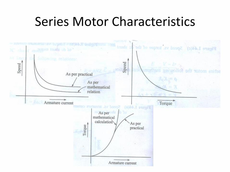
Series Motor Characteristics

• Torque is proportional to square of armature current
• Gives more torque per ampere
• Disadvantage is torque is zero the speed goes to infinity
• The centrifugal force experienced will damage the armature.
• Therefore some safety measures should be taken if the load is connected via belts
DC Series Motor

• speed drops with the load
• Speed cannot be controlled because field current totally depends on load(field series with armature

Speed Control of Series Motor
• There is only one efficient method of speed control
• That is to change the voltage of the motor
• Increase of terminal voltage increase the speed for any given torque
• Other method is insertion of series resistor to the circuit
• This is a wasteful method

Applications of Series Motors
• Use for applications need high starting torque
• For light loads speed is high and vise versa
• Well suited for trains and cranes

DC Shunt Motor

Shunt Motor
• Compared to series motor, shunt motor field is made out of thin wire
• It can handle small field current
• At start , torque will be less compared to series motor
• Speed torque characteristics should be a straight line if the flux in the machine is constant for a particular load

• Due to armature reaction, flux per pole reduces
• Due to back EMF armature current reduces
• When the motor reaches full RPM the speed is fairly constant
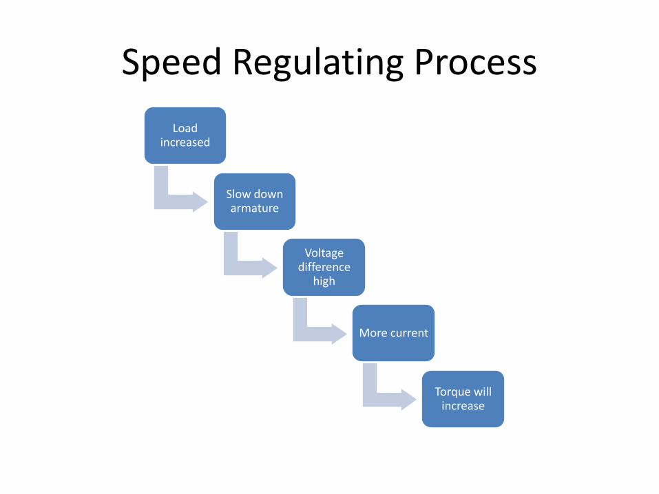
Speed Regulating Process
Load increased
Slow down armature
Voltage difference
high
More current
Torque will increase

Controlling the Speed
• Shunt motors speed can be controlled
• It will use back EMF to maintain speed
• If the load is slightly increased shaft will slow down slightly

Methods of Speed Control
• There are two common scheme of speed control
– Armature voltage control
– Field current control
• Less common method
– Armature current control
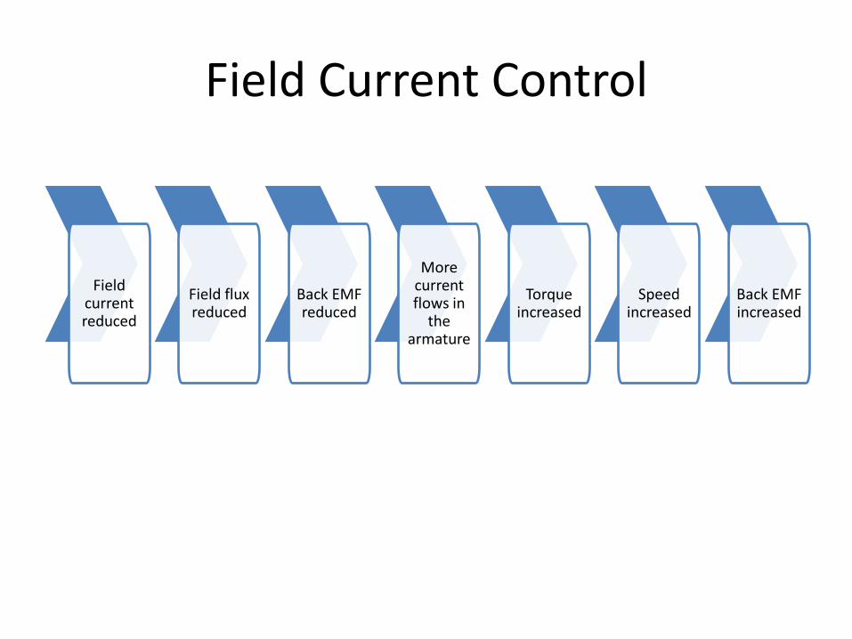
Field Current Control
Field current reduced
Field flux reduced
Back EMF reduced
More current flows in
the armature
Torque increased
Speed increased
Back EMF increased

Consequences of Field Control (at very low speed)
No load speed will increase(see the graph)
Increase in armature current caused by EMF reduction not enough to
compensate Field reduction
Increase in field current will decrease speed
Not control purposes operates at speeds
closer to stall conditions

Disadvantage of Field Control
ω
T
Rf1
Rf2
Rf1>Rf2
ω
T Tfl Tfl

Armature Voltage Control
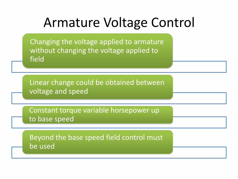
Armature Voltage Control Changing the voltage applied to armature without changing the voltage applied to field
Linear change could be obtained between voltage and speed
Constant torque variable horsepower up to base speed
Beyond the base speed field control must be used


Armature current control
• Obtained by controlling armature current by inserting a rheostat in series with armature
• This is a wasteful method
• This method is rarely used
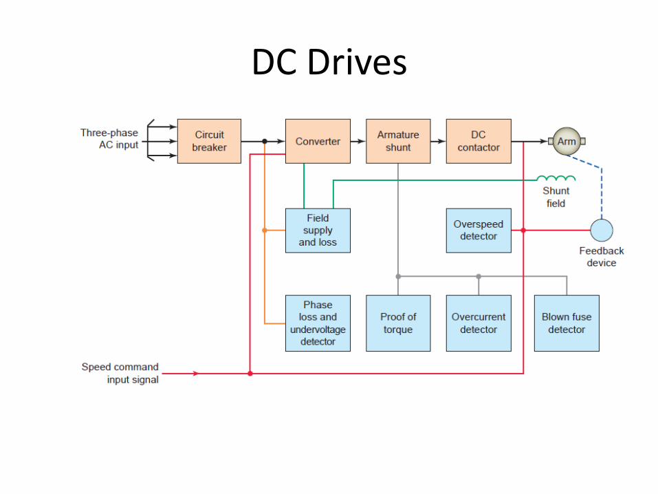
DC Drives

DC Compound Motor

• As the load increases MMF of series field increases, but shunt field remain constant.\
• Same controlling techniques as shunt motors can be used for compound motors.
• This is almost never used with speed control

DC Motor Starters
• Why starter is required?
Manual motor starter

DC Motor Starters
Across the line starter

Definite Time Reduced Voltage DC Starter Pressing the start button energizes the M and TR coils. • Auxiliary memory contact M closes to seal in and maintain M and TR coils. • The M main contact closes, starting the motor at reduced current and torque with the resistor connected in series with the armature. • After a preset time delay, timed contact TR closes to energize contactor R coil. • Contact R closes, bypassing the resistor and allowing full line voltage to be applied to the armature. • The starting method is closed transition. • Starting resistance can be shorted out in one or more steps, depending on motor size and the smoothness of acceleration desired. • The shunt field has full line voltage applied to it any time the motor is on. Figure 8-25 illustrates variable-voltage acceleration of

Variable voltage acceleration of a DC shunt motor

+
DC Motor Reversing Circuits
+ + -

Motor Reversing Circuits
