characteristic analysis and optimization of a four- bar
TRANSCRIPT

Characteristic Analysis and Optimization of a Four-bar Compliant Mechanism with Single FlexibleMemberShanzeng Liu ( [email protected] )
China University of Mining and Technology https://orcid.org/0000-0002-9174-8174Zhaopeng Sun
China University of Mining Technology: China University of Mining and TechnologyGang Shen
China University of Mining Technology: China University of Mining and TechnologyYunwang Li
China University of Mining Technology: China University of Mining and Technology
Original Article
Keywords: compliant mechanism, pseudo-rigid body model, bistable characteristics, energy method,optimal design
Posted Date: April 13th, 2021
DOI: https://doi.org/10.21203/rs.3.rs-397919/v1
License: This work is licensed under a Creative Commons Attribution 4.0 International License. Read Full License
CHINESE JOURNAL OF MECHANICAL ENGINEERING Vol. 27,aNo. 4,a2014
1
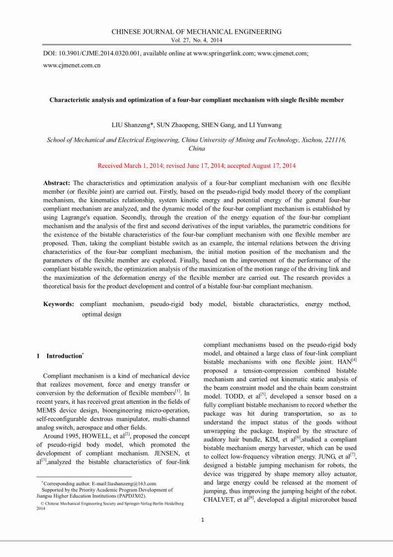
DOI: 10.3901/CJME.2014.0320.001, available online at www.springerlink.com; www.cjmenet.com;
www.cjmenet.com.cn
Characteristic analysis and optimization of a four-bar compliant mechanism with single flexible member
LIU Shanzeng*, SUN Zhaopeng, SHEN Gang, and LI Yunwang
School of Mechanical and Electrical Engineering, China University of Mining and Technology, Xuzhou, 221116, China
Received March 1, 2014; revised June 17, 2014; accepted August 17, 2014
Abstract: The characteristics and optimization analysis of a four-bar compliant mechanism with one flexible member (or flexible joint) are carried out. Firstly, based on the pseudo-rigid body model theory of the compliant mechanism, the kinematics relationship, system kinetic energy and potential energy of the general four-bar compliant mechanism are analyzed, and the dynamic model of the four-bar compliant mechanism is established by using Lagrange's equation. Secondly, through the creation of the energy equation of the four-bar compliant mechanism and the analysis of the first and second derivatives of the input variables, the parametric conditions for the existence of the bistable characteristics of the four-bar compliant mechanism with one flexible member are proposed. Then, taking the compliant bistable switch as an example, the internal relations between the driving characteristics of the four-bar compliant mechanism, the initial motion position of the mechanism and the parameters of the flexible member are explored. Finally, based on the improvement of the performance of the compliant bistable switch, the optimization analysis of the maximization of the motion range of the driving link and the maximization of the deformation energy of the flexible member are carried out. The research provides a theoretical basis for the product development and control of a bistable four-bar compliant mechanism. Keywords: compliant mechanism, pseudo-rigid body model, bistable characteristics, energy method,
optimal design
1 Introduction
Compliant mechanism is a kind of mechanical device that realizes movement, force and energy transfer or conversion by the deformation of flexible members[1]. In recent years, it has received great attention in the fields of MEMS device design, bioengineering micro-operation, self-reconfigurable dextrous manipulator, multi-channel analog switch, aerospace and other fields.
Around 1995, HOWELL, et al[2], proposed the concept of pseudo-rigid body model, which promoted the development of compliant mechanism. JENSEN, et al[3],analyzed the bistable characteristics of four-link
Corresponding author. E-mail:[email protected] Supported by the Priority Academic Program Development of
Jiangsu Higher Education Institutions (PAPDJX02). © Chinese Mechanical Engineering Society and Springer-Verlag Berlin Heidelberg
2014
compliant mechanisms based on the pseudo-rigid body model, and obtained a large class of four-link compliant bistable mechanisms with one flexible joint. HAN[4] proposed a tension-compression combined bistable mechanism and carried out kinematic static analysis of the beam constraint model and the chain beam constraint model. TODD, et al[5], developed a sensor based on a fully compliant bistable mechanism to record whether the package was hit during transportation, so as to understand the impact status of the goods without unwrapping the package. Inspired by the structure of auditory hair bundle, KIM, et al[6],studied a compliant bistable mechanism energy harvester, which can be used to collect low-frequency vibration energy. JUNG, et al[7], designed a bistable jumping mechanism for robots, the device was triggered by shape memory alloy actuator, and large energy could be released at the moment of jumping, thus improving the jumping height of the robot. CHALVET, et al[8], developed a digital microrobot based

LIU Shanzeng, et al: Characteristic analysis and optimization of a four-bar compliant mechanism with single flexible member
2
on four bistable modules. Due to the use of a bistable mechanism, the precise micro-positioning of the robot was realized by only open-loop control. HETRIK, et al[9], adopted the topology optimization method and took satisfying the motion constraints and maximizing the energy as the objective function to carry out the optimization analysis of the compliant mechanism. ZHAN, et al[10], evaluated the static strength of the structure with the sum of the magnitude of the signed von Mises stress and the mean absolute value, and used the modified Goodman fatigue criteria to evaluate the structural fatigue strength. Then, the P norm approach was used to approximate the local element stresses, and the optimization analysis of the continuum structure was carried out. Based on the principle of compliant mechanism, Wang, et al[11], discussed the structural design of dielectric elastomer actuator by using topology optimization method. PEI, et al[12], discussed the design of compliant straight-line mechanisms using flexural joints. WANG, et al[13], adopted the finite element method and Lagrange equation to carry out the dynamic modeling of the plane compliant mechanism and the dynamic stress analysis of the flexible element. LI, et al[14], summarized the electroactive bistable mechanism and introduced the electroactive bistable mechanism with in-plane mode and out-of-plane mode with respect to the motion direction and its application in soft robot.
In this paper, based on the pseudo-rigid body model theory, the conditions for the bistable characteristics of a four-bar compliant mechanism with one flexible member are derived by using the energy method. Combining with an application example of a compliant bistable switch, the driving characteristics and mechanism parameters of the four-bar compliant mechanism are optimized. 2 Dynamic analysis
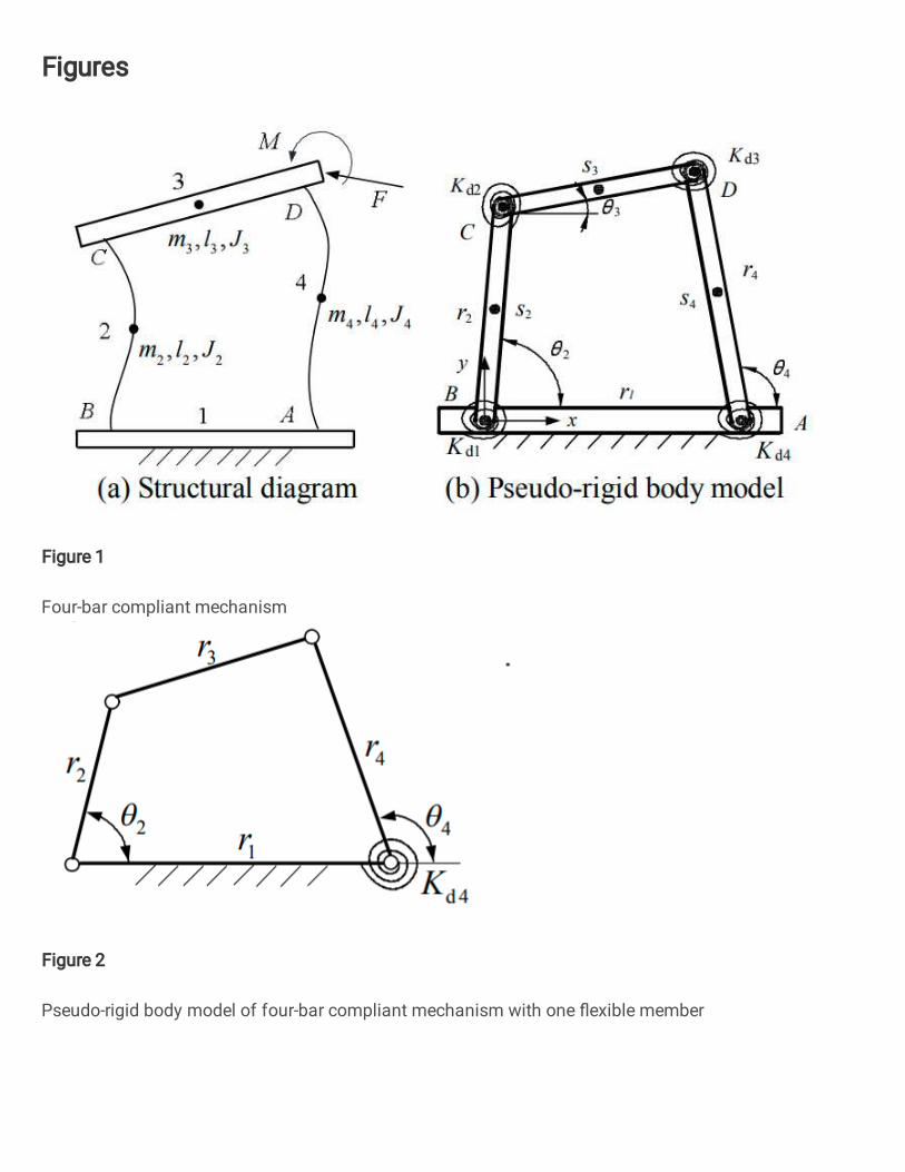
A four-bar compliant mechanism and its pseudo-rigid body model are shown in Fig. 1. The four-bar compliant mechanism consists of two flexible members (ie, links 2 and 4) and a rigid member (ie, link 3). The length of the link 2, the link 3 and the link 4 is denoted as li (i=2,3,4) and the mass is denoted as mi (i=2,3,4), and the moment of inertia with respect to the center of mass is denoted as Ji (i=2,3,4). The pseudo-rigid body model contains four torsional springs, and the dynamic spring constant of the torsional springs is denoted as Kdi (i=1,2,3,4).
Using γ to represent the characteristic radius factor of the flexible member, then the rotation radii of the equivalent members 2 and 4 in the pseudo-rigid body model can be expressed as r2=γ2l2 and r4=γ4l4, respectively, and the centroids of the equivalent members 2, 4 and link 3 are denoted as S2, S4 and S3, respectively.
3 3 3, ,l Jm
2 2 2, ,l Jm4 4 4, ,l Jm
r2
r1
Kd2
Kd3
K d1 K d4
A
D
B
C
2
3
4
r4
4ss2
s3
x
y
(a) Structural diagram (b) Pseudo-rigid body model
Fig. 1. Four-bar compliant mechanism
2.1 Kinematics The rotation angle, angular velocity and angular
acceleration of the link 2 in Fig. 1(b) are represented by θ2, ω2= 2 and 2 respectively. Taking point B as the origin of the coordinates and establishing a Cartesian coordinate system as shown in Fig. 1(b), we get
2 2 3 3 1 4 4
2 2 3 3 4 4
cos cos cossin sin sin
r r r rr r r
(1)
Taking θ2 as a variable and solving Eq. (1), we have 2 2 2
3 2arctan b a b ca c
(2)
2 2 2
4 2arctan b a b da d
(3)
12
2
cos rar
2 2 2 2
4 1 2 3 1 2 2
2 3
2 cos2
r r r r r rcr r
2sinb 2 2 2 2
1 4 2 3 1 2 2
2 4
2 cos2
r r r r r rdr r
At the same time, the first derivative of Eq. (1) with respect to time t can be obtained
2 3 3 2 1 2 23 2
2 3 3 2 1 3 3
sin( ) sinsin( ) sin
r r r rr r r r
(4)
2 4 4 2 1 2 24 2
2 4 4 2 1 4 4
sin( ) sinsin( ) sin
r r r rr r r r
(5)
Suppose the link 3 is a homogeneous bar with uniform cross section, and its centroid coordinate is (x3, y3), then
3 2 2 3 3
3 2 2 3 3
1cos cos21sin sin2
x r r
y r r
(6)
From Eq. (6), the centroid velocity VS3 of the link 3 can be expressed as
2 2 2 2 2S3 2 2 3 3 2 3 2 3 2 3
1 cos( )4
V r r r r
(7)
Similarly, the centroid velocities VS2 and VS4 of the link 2 and link 4 can be expressed as
S2 2 2
S4 4 4
1212
V r
V r
(8)

3
2.2 Kinetic energy of system
The kinetic energy Ek2, Ek3 and Ek4 of the links 2, 3 and 4 in the four-bar compliant mechanism can be expressed as follows
2 2k2 2 S2 2 2
1 12 2
E m V J (9)
2 2k3 3 S3 3 3
1 12 2
E m V J (10)
2 2k4 4 S4 4 4
1 12 2
E m V J
(11)
Hence, the total kinetic energy Ek of the four-bar compliant mechanism is given by
4
k k2
ii
E E
(12)
2.3 Potential energy of system If the energy loss caused by the deformation of the
flexible member and the friction between the members are ignored, then the elastic potential energy Ep stored by the flexible member is equal to the work done by the forces and moments acting on the member.
When the end of the flexible link is subjected to a moment M, as shown in Fig.1. Assuming that the pseudo-rigid body angle φ=0 when the flexible link is in the initial position, the angle that the end of the flexible link has rotated after being acted on by the moment M is θ. Then the elastic potential energy Ep1 of the flexible link can be expressed as
p1 θ0 0d dE M c M
(13)
φEIM Kl
(14)
where cθ denotes the parametric angle coefficient, Kφ
denotes the torsion spring stiffness coefficient, and l denotes the length of the flexible link.
When the end of the flexible link is subjected to a force F, as shown in Fig.1. If the displacement of the end of the flexible link under the action of the force F is s. Then the elastic potential energy Ep2 of the flexible link can be expressed as
p2 t0 0d d
sE F s F l
(15)
where Ft denotes the tangential component of the force F along the trajectory of the end of the flexible link, namely
t φ 2
EIF Kl
(16)
It is not difficult to obtain from equations (13) - (16) that the unified expression of the elastic potential energy of the equivalent dynamic model of the flexible link is
2p d
12i i iE K (17)
where, φi (i=1,2,3,4) and Kdi (i=1,2,3,4) are the pseudo-rigid body angle and the dynamic spring constant of the torsion spring at the ith joint of the mechanism,
respectively. So the elastic potential energy Ep of the mechanism
can be expressed as 4 4 4
2 2p p d d
1 1 1
1 12 2i i i i i
i i iE E K K
(18)
where, ϕi (i=1,2,3,4) denotes the rotation angle of the torsion spring at the ith joint in the mechanism. Assuming that the position angle of the ith link is θi0 (i=2,3,4) when the torsion spring is not deformed, we have
1 2 20
2 2 20 3 30
3 4 40 3 30
4 4 40
( ) ( )( ) ( )
(19)
2.4 Dynamics The Lagrange's equations of the second kind is
expressed as dd i
i i
L Lt
Q
q q (20)
where, L denotes the Lagrangian function, qi (i=1,2, 3,…,n) denotes the generalized coordinate variables of the system, Qi denotes the generalized force.
By substituting equations (12) and (18) into Eq. (20) and simplifying, the dynamic equation of the four-bar compliant mechanism can be written as
22 2 2( ) iM c
e (21)
where, i denotes the generalized force of the mechanism, Me, c, and φ(θ2) are functions of the structural parameters of the mechanism. From Eq. (21), the dynamic characteristics of the four-bar compliant mechanism (such as natural frequency, stress, etc.) can be solved. 3 Analysis of bistable characteristics
Eq. (1) takes the first and second derivatives of angle
variable θ2, and solves and simplifies them, we get 3 2 4 2
2 3 3 4
d sin( )d sin( )
rr
(22)
2 3 24
2 4 3 4
sin( )dd sin( )
rr
(23)
24 23 2 4
22 3 3 4 2
cosd d 1d sin d
rr
4 2 3 4 3 42
3 4 2 2
sin cos d dsin d d
(24)
23 2 34 2
22 4 3 4 2
cos dd 1d sin d
rr
3 2 3 4 3 42
3 4 2 2
sin cos d dsin d d
(25)

LIU Shanzeng, et al: Characteristic analysis and optimization of a four-bar compliant mechanism with single flexible member
4
When a four-bar compliant mechanism contains one flexible member, without loss of generality, it is assumed that the torsion spring (or flexible joint) is located at the joint between the drived link and the frame, and its pseudo-rigid body model is shown in Fig. 2. According to equations (18) and (19), the energy equation of the mechanism can be written as
2p d4 4 40
12
E K
(26)
Eq. (26) finds the first and second derivatives of the variable θ2, we get
2r 4r
3r
1r2 4
d 4K Fig. 2. Pseudo-rigid body model of four-bar compliant
mechanism with one flexible member
p 4d4 4 40
2 2
d dd dE
K
(27)
22 2
p 4 4d4 4 40 d42 2
2 2 2
d d dd d d
EK K
(28)
Assuming 3 4sin( ) 0 , combine Eq. (23) and Eq.
(27), and set Eq. (27) equal to zero, we get
4 40
3 2
or
0
sin( ) 0
(29)
According to Eq. (29), it is not difficult to obtain the solution of the mechanism in the equilibrium position as follows:
when 4 40= ,
2 20
4 402 20
1 4 40
orsin2arctan
cosr
r r
(30)
when 3 2sin( ) 0 ,
2 3
2 3
or
(31)
Substitute the two values of θ2 in Eq. (30) into Eq. (28) respectively (in this case, in general 2 3 ), and both can be obtained
2p
22
dd
E
0
It can be seen that the configuration of the four-bar compliant mechanism corresponding to each value of θ2 in Eq. (30) is the stable equilibrium position.
Substituting the two values of θ2 in Eq. (31) into Eq. (28), we get
d 4 2 2 3 4 402 32
3 4 4 3P22 d 4 2 2 3 4 40
2 33 4 4 3
+, if
sindd
, if πsin
K r r rr rE
K r r rr r
( )
( )
(32)
It can be seen from Eq. (32) that the bistable characteristics of the four-bar compliant mechanism are closely related to the size of each link, the position of the flexible joint and the initial motion position of the mechanism (i.e. the configuration of the mechanism without deformation of the flexible joint).
At the same time, if the four-bar compliant mechanism has bistable characteristics, then the mechanism should have an unstable equilibrium position between the two stable equilibrium positions. When θ2=θ3 and θ2=θ3±π (where the ± should be selected according to the mechanism parameters), it is not difficult to find that links 2 and 3 are in the collinear or overlapping collinear configuration (i.e., the singularity configuration of the mechanism) respectively. If the mechanism is slightly disturbed at this time, it will deviate from its original position. Therefore, it can be determined that θ2=θ3 and θ2=θ3±π are the unstable equilibrium positions of the mechanism.
According to the foregoing analysis, it can be seen that if a four-bar compliant mechanism with one flexible member (or flexible joint) has bistable characteristics, then the mechanism should have a collinear configuration of the two links, and the torsion spring (i.e. flexible joint) must be installed on the opposite side of the two links with collinear configuration. In other words, the sum of the lengths of the two members connected to the flexible joint should be greater than the sum of the lengths of the other two members, or the difference between the lengths of the two members connected to the flexible joint is less than the difference between the lengths of the other two members. So, we have
a b c d
a b c d
or
r r r r
r r r r
(33)
where, ra, rb denote the lengths of the two members connected with the flexible joint, respectively, and rc, rd denote the lengths of the other two members, respectively.
Corresponding to Eq. (33), the selection principle of the initial motion angle θ0 of the flexible joint without deformation is
1 0 2 (34) 22 2
a b c d
a b1 arccos
2r r r r
r r

5
22 2a b c d
a b2 arccos
2r r r r
r r
4 Drive characteristic analysis
The compliant bistable switch is a typical application of the four-bar compliant mechanism with single flexible member, as shown in Fig. 3. In the mechanism, positions A, B and C are hinges, member 2 is a driving link, and member 4 is a flexible link connected to the frame in the form of a cantilever beam. The angle between the frame and the horizontal plane is =2°, the length and centroid of each member are respectively denoted as li (i=1,2,3,4) and ci (i=2,3,4), and the pseudo-rigid body model parameters, See Table 1.
1l
2r
2c3c
3r
4c 4l
Fig. 3. Compliant bistable switch
Table 1. Pseudo-rigid model parameters
r1 (mm) r2 (mm) r3 (mm) l4 (mm) γ Kφ
26 14.8 7.6 10.6 0.85 2.676
4.1 Initial position influence
According to Table 1, the calculation shows that the motion range of the driving link 2 is -36.4°~36.4°, the motion range of the link 3 and the drived rocker 4 are -65°~32° and -32°~57°, respectively. The angular displacement relationship curves of each member are shown in Fig.4.
Fig. 4. Angular displacement curves of mechanism
When links 2 and 3 are collinear (such as
θ2=θ3=-19.7°), the mechanism is in an unstable equilibrium position. Then the two stable equilibrium positions of the mechanism should be distributed on both sides of the unstable equilibrium position, and the initial motion position of the mechanism should be one of its
stable equilibrium positions. Therefore, according to the angular displacement curves of each member in Fig.4 (or calculated by Eq. (34)), the value range of θ40 can be determined to be 32°~57°.
During the movement of the mechanism, the work done by the driving torque Tin on the link 2 and the deformation energy stored on the flexible link 4 form a functional conversion. Thus, the work done by the driving torque on the link 2 can be expressed as
0
P in 22
d4 4 402d 1E T K
(35)
Eq. (35) takes the derivative of θ2, we get
2 3 2in d4 4 40
4 3 4
sinsin
rT K
r
(36)
It can be seen that the driving torque Tin is numerically equal to the first derivative of the energy equation with respect to the driving variable, and the zero point of the derivative equation is the equilibrium position of the mechanism.
In Fig. 3, the material of the flexible link 4 is polypropylene, and the structural parameters and material properties are shown in Table 2. Then, the dynamic spring constant of the torsion spring in the corresponding pseudo-rigid body model is
324 4
d 4 φ φ4 4
N m / rad1.33 10 12
Eb hEIK K Kl l
Table 2. Parameters of flexible link
Density ρ(Kg/m3)
Width w4(mm)
Thicknes h4 (mm)
Elastic modulus E4 (N/m2)
Inertia moment I4 (m4)
910 5 0.5 1.35×10⁹ 5.21×10⁻¹⁴
-40 -30 -20 -10 0-0.012
-0.008
-0.004
0.000
0.004
0.008
0.012
0.016
40 =55 40 =50
40 =45 40 =40
40 =35
Torq
ue T
in/
10-2
Nm
Input angle 2/( Fig. 5. Relation curve of Tin and θ40
Now, the relationship curve between the driving torque
Tin of the link 2 and the initial position θ40 of the member 4 can be obtained from Eq. (36), as shown in Fig.5. The zero point of the driving torque Tin corresponds to the two stable equilibrium positions and an unstable equilibrium position of the four-bar compliant mechanism, and the intersection point of all curves is the unstable equilibrium

LIU Shanzeng, et al: Characteristic analysis and optimization of a four-bar compliant mechanism with single flexible member
6
position. It can be seen that the driving torque Tin of the link 2 and the motion range of the mechanism have an approximately inverse relationship with the initial angle θ40. If the installation space between the moving and static contacts of the bistable switch is taken into account, it is advisable that θ40=40°. At this time, the two stable equilibrium positions of the mechanism are θ2=-35.6° and θ2=1.5°, respectively. 4.2 Influence of torsion spring stiffness
Given that the compliant bistable switch is in the open state at the initial position θ20=-35.6°, the selection range of the torsion spring stiffness is 0~0.02N·m/rad, the relationship curve between the driving torque Tin and the torsion spring stiffness Kd4, as shown in Fig. 6. It can be seen that no matter what the value of Kd4 is, the change trend of the driving torque Tin in the motion range of the mechanism is the same, and the variation range of the driving torque increases with the increase of the torsion spring stiffness.
Fig. 6. Relation curve of Tin and Kd4
The selection of the stiffness parameters of the flexible
member in the compliant bistable switch depends on factors such as the drive mode, mechanical structure, energy consumption and control. At the same time, the key of bistable switch design is to select a suitable driving torque for the mechanism. The schematic diagram of the preliminarily designed compliant bistable switch structure is shown in Fig.7.
Fig. 7 Schematic diagram of compliant bistable switch
Meanwhile, the driving torque acting on the handle is
3 2in 4
3 4
14.8 sin2π0.01339 9 sin
T
(37)
5 Optimization design
The compliant bistable switch shown in Fig. 7 is made of polypropylene and its initial structure and material parameters are shown in Tables 1 and 2. In the following, the flexible link is used as the optimization object, its structural parameters are taken as the design variables, and the maximum motion range and strain energy of the mechanism are taken as the goals to carry out the optimal design of compliant bistable switch.
5.1 Motion range optimization (1) Design variables
Select the length of the flexible link and the initial motion position as design variables, we have
x=(x1, x2)T=(l4, θ20)T (38) (2) Objective function
One stable equilibrium position of the compliant bistable switch is its initial motion position (i.e., θ2=θ20), and the other stable equilibrium position can be expressed as
4 402 20
1 4 40
sin2arctancos
rr r
(39)
Based on reliability and installation space considerations, in order to maximize the contact distance of the compliant bistable switch, the angle between the two stable equilibrium positions needs to be maximized, namely
4 40max 2 4 20 20
1 4 40
0.85 sin( ) ( , ) 2 arctan0.85 cos
lf lr l
x
(40)
(3) Constraint conditions 1) Member length constraint In the mechanism of compliant bistable switch shown
in Fig.3, if the frame length r1 is the longest, l4 must satisfy the inequality r1≤r2+r3+0.85l4, that is, 4.3 mm≤l4≤30.5 mm; If the length of the flexible link l4 is the longest, l4 must satisfy the inequality 0.85l4≤r1+r2+r3, that is, 30.5 mm≤l4≤56.9 mm. Therefore, the value range of l4 is 4.3 mm≤l4≤56.9mm. In addition, from Eq. (33), the value range of the length l4 of the flexible link is 0<l4 or 22.1 mm≤l4≤39 mm. In summary, the value of flexible link length l4 is shown in Table 3.
Table 3. Subdivision table of the value range of l4
Type Category condition Value range of l4 1 l4 is the largest 39mm<l4≤56.9mm
2 r1 is the largest, l4 is
the shortest 4.3mm<l4≤8.8mm
3
longest link length + shortest link
length > sum of the other two link
lengths r1 is the largest, r3 is
the shortest 8.8mm<l4≤22.1m
m
4 longest link length + shortest link length ≤ sum of the other two link lengths, and r3 is
the shortest 22.1mm≤l4≤39mm
2) Initial position constraint According to the value type of l4 in Table 3, the value

7
range of variable θ2 is discussed in the following section. For Type 1, the limit position of the mechanism occurs
when the link 2 is collinear with the link 3 or the link 2 is overlap with the link 4, as shown in Fig.8. The value range of the variable θ2 can be obtained as
2
Fig. 8. No.1 limit position analysis of mechanism
2 2 2 2
1 2 4 32
1 2
2 2 2 21 2 4 3
21 2
( )arccos π2
or( )π arccos
2
r r r rr r
r r r rr r
(41)
For Types 2 and 3, the limit position of the mechanism occurs when the link 2 is collinear with the link 3 or the link 3 is collinear with link 4, as shown in Fig.9. Then the value range of variable θ2 is
2 2 2 2 2 21 2 3 4 1 2 3 4
21 2 1 2
( ) ( )arccos arccos
2 2r r r r r r r r
rr rr
(42)
2
Fig. 9. No.2 limit position analysis of mechanism
2
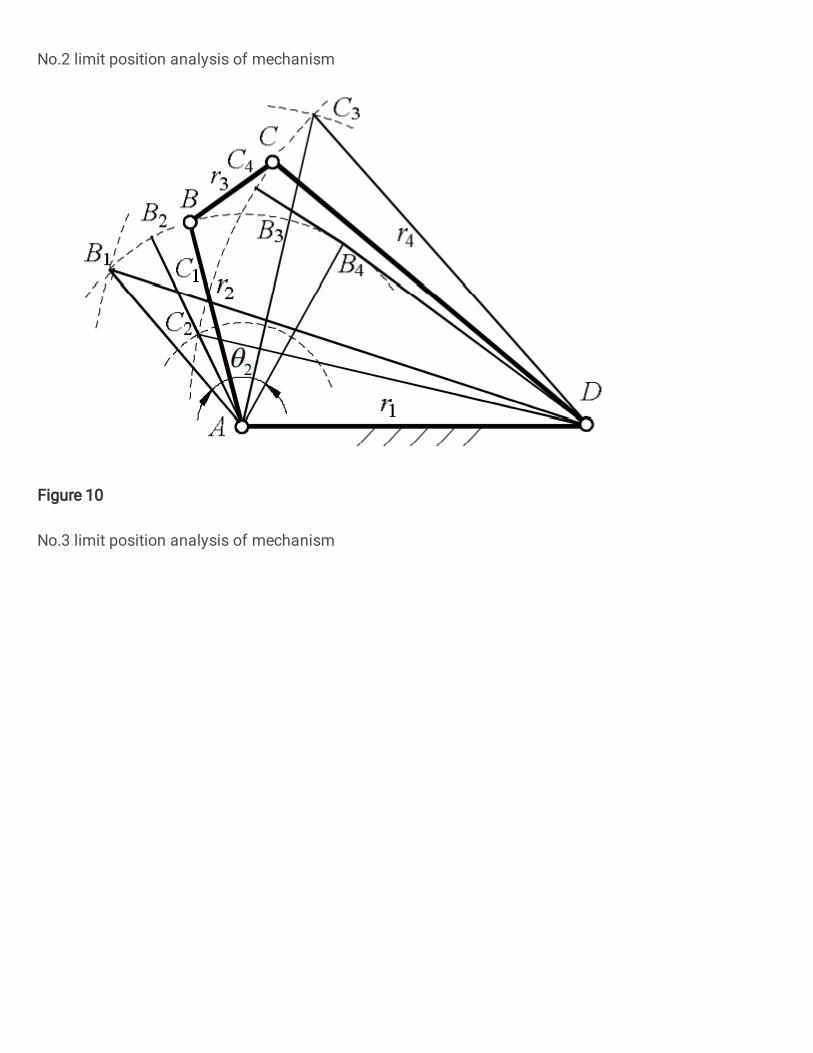
Fig. 10. No.3 limit position analysis of mechanism
For Type4, the limit position of the mechanism occurs
when the link 2 and the link 3 are collinear or overlap, and when the link 3 and the link 4 are collinear or overlap,
as shown in Fig.10. So, the value range of variable θ2 is 2 2 2 2 2 2
1 2 4 3 1 2 3 42
1 2 1 2
( ) ( )arccos arccos2 2
r r r r r r r rrr rr
(43)
(4) Optimization analysis When the value range of l4 is 4.3mm< l4 ≤ 8.8mm, the
motion range of the mechanism is shown in Fig.11. It is not difficult to find that with the increase of l4, the value range of the initial motion position θ20 of the mechanism, the change amplitude and the maximum value of the motion range of the mechanism are all increasing. When l4= 8.8 mm, the motion range of the mechanism (i.e., Δθ2) to obtain the maximum value of about 45.8 °.
2M
otion range /(
)
20
/( )
Initial position
4 / m
m
Link len
gth l
Fig. 11. Motion range of mechanism when 4.3mm<l4≤8.8mm
When the value range of l4 is 8.8mm<l4≤ 22.1mm, the
motion range of the mechanism is shown in Fig.12. It can be concluded that with the increase of l4, the value range of the initial motion position θ20 becomes larger, and the motion range of the mechanism also increases slowly, but it does not change after increasing to a certain extent. The maximum motion range of the mechanism is about 61.8° (at this time l4=14.4mm).
2M
otion range /(
)
20
/( )
Initial position
4 / mm
Link length l
Fig. 12 Motion range of mechanism when 8.8mm<l4≤22.1mm
When the value range of l4 is 22.1mm<l4≤39mm, the
motion range of the mechanism is shown in Fig.13. Similarly, with the increase of l4, the value range of the initial position θ20 of the mechanism also increases, but the motion range of the mechanism basically remains unchanged, and the maximum value of the motion range of the mechanism is about 61.8°.

LIU Shanzeng, et al: Characteristic analysis and optimization of a four-bar compliant mechanism with single flexible member
8
2M
otio
n ra
nge
/(
)
4 / m
m
Link len
gth l
20
/( )
Initial position
Fig. 13 Motion range of mechanism when 22.1mm<l4≤39mm
2M
otio
n ra
nge
/(
)
4 / m
m
Link len
gth l
20
/( )
Initial position
Fig. 14 Motion range of mechanism when 39mm<l4≤56.9mm
When the value range of l4 is 39mm<l4≤56.9mm, the motion range of the mechanism is shown in Fig.14. It can be seen that with the increase of l4, the value range of the initial motion position θ20 gradually decreases, but the motion range of the mechanism first remains unchanged and then decreases, and the maximum value of the motion range of the mechanism is about 61.8°.
According to the foregoing analysis, taking into account factors such as the ease of control and mechanical efficiency of the compliant mechanism, 14.4mm<l4≤ 16.2mm and 39mm<l4≤44.5mm are selected as the value ranges for mechanism parameter optimization. Then, the optimal solution with the goal of maximizing the motion range of the mechanism can be obtained, as shown in Table 4. Note that if the value of l4 is too large, the stability of the mechanism will become worse.
Table 4. Optimization results of l4
l4 /mm Optimization solution /mm θ20/ (°) Δθ2/(°)
14.4<l4≤16.2 l4=16.2 -23.6~23.7 61.8
39<l4≤44.5 l4=44.5 167.1~180 or -180~167.3 61.8
5.2 Strain energy optimization Taking the cross-sectional parameters of the flexible
link as the design variable, the optimal design of the strain energy performance of the compliant bistable switch is carried out. (1) Design variables
Taking the cross-section parameters of the flexible link as design variables, we get
x=(x1, x2)T=(w4, h4)T (44) where, w4 and h4 are the cross-sectional width and thickness of the flexible link, respectively. (2) Objective function
The strain energy of the mechanism is
23p φ 4 4 4 40
124
E K Ew h
(45)
When the initial motion position and motion range parameters of the mechanism are given, the strain energy of the mechanism is only determined by the width and thickness parameters of the cross section of the flexible link. Thus, the objective function can be expressed as
f(x) =f(w4,h4)= w4h43 (46)
(3)Constraint conditions According to experience(See references [1,13]), the
optimal solution range of w4 and h4 are given as 2mm~6mm and 0.1mm~1mm, respectively. At the same time, in order to improve the ability of the flexible link to store strain energy, the first-order natural frequency of the mechanism is set between 45 Hz and 60 Hz. Then the constraint conditions can be expressed as
1
2
3
4 4
5 4
6 4
7 4
g 60 0g 45 0g 28.6 0
2 06 0
1 00.1 0
x fx fx
g x wg x wg x hg x h
(47)
(4) Optimization Results By solving equations (44), (46) and (47), the
optimization results can be obtained, as shown in Table 5. The results show that the strain energy performance of the optimized compliant bistable switch is increased by about 11.10%, and the maximum stress of the flexible link is also improved to a large extent.
Table 5. Optimization results based on strain energy
Serial number
w4 /mm h4 /mm σmax
/MPa f /Hz
Strain energy
increment /(%)
1 5.0~5.6 0.24 11.066 57.874 11.06~12.39 2 5.7~6 0.23 10.605 55.495 11.10~11.70
6 Conclusion

9
The bistable characteristics of a four-bar compliant mechanism with a flexible member were analyzed. Taking a compliant bistable switch as an example, the driving characteristics and structural parameter optimization of the four-bar compliant mechanism were carried out. The conclusions are as follows:
(1) The condition for the existence of bistable characteristics of a four-bar compliant mechanism with one flexible member is that the sum of the lengths of the two links connected by the flexible joint should be greater than the sum of the lengths of the other two links, or the difference of the lengths of the two links connected by flexible joints should be less than the difference of the lengths of the other two links.
(2) The length parameter and initial motion position of the flexible member in the four-bar compliant mechanism have an important influence on the kinematics and driving characteristics of the mechanism.
(3) By optimizing the structural parameters such as the length and cross section of the flexible member in the four-bar compliant mechanism, the kinematics and dynamic characteristics of the mechanism can be improved. References [1] LIU Shanzeng, DAI Jiansheng, LI Aimin, SUN Zhaopeng, FENG
Shizhe, CAO Guohua. Analysis of Frequency Characteristics and Sensitivity of Compliant Mechanisms[J]. Chinese Journal of Mechanical Engineering, 2016, 29(4): 680-693.
[2] HOWELL L L, MIDHA A. Parametric deflection approximations for end loaded large deflection beams in compliant mechanisms [J]. Transaction of the ASME, Journal of Mechanisms in Design, 1995, 117(3): 156-165.
[3] JENSEN B, HPWELL L. Identification of compliant pseudo-rigid-body four-link mechanism configurations resulting in bistable behavior [J]. Journal of Mechanical Design, 2003, 125(11): 701-708.
[4] HAN Qi. On accurate modeling of tensural muiltistable compliant mechanisms [D]. Xian: Xidian University, 2018. (in Chinese)
[5] TODD B, PHILLIPS M, SCHULTZ S M, HAWKINS A R, JENSEN B D. Low-cost RFID threshold shock sensors [J]. IEEE Sensors Journal, 2009, 9 (4): 464–469.
[6] KIM G W, KIM J. Compliant bistable mechanism for low frequency vibration energy harvester inspired by auditory hair bundle structures[J]. Smart Materials and Structures, 2013, 22(1): 014005.
[7] JUNG S P, JUNG G P, KOH J S, LEE D U, CHO K J. Fabrication of composite and sheet metal laminated bistable jumping mechanism [J]. ASME Journal of Mechanisms and Robotics, 2015,7(7): 021010.
[8] VINCENT Chalvet, YASSINE Haddab, PHILIPPE Lutz. A microfabricated planar digital microrobot for precise positioning based on bistable modules [J]. IEEE Transaction on Robotics, 013, 29 (3): 641-649.
[9] HETRIK J A, KOTA S. An energy formulation for parametric size and shape optimization of compliant mechanisms [J]. Transaction of the ASME, Journal of Mechanisms in Design, 1999, 121(3): 229-233.
[10] ZHAN Jinqing, PENG Yiping, LIU Min, HUANG Zhichao. Topological design of continuum structure with multiple performance constraints J]. Computer Integrated Manufacturing
Systems, https://kns.cnki.net/kcms/detail/11. 5946.tp.20201203. 0950.002.html. (in Chinese)
[11] WANG Nianfeng, GUO Hao, CHEN Bicheng, CUI Chaoyu, ZHANG Xianmin. Integrated Design of Actuation and Mechanism of Dielectric Elastomers Using Topology Optimization Based on Fat Bezier Curves [J]. Soft Robotics, 2019, 6(5): 644-656.
[12] PEI Xu, YU Jingjun, ZONG Guanghua, BI Shusheng. Design of compliant straight-line mechanisms using flexural joints [J]. Chinese Journal of Mechanical Enginering, 2014, 27(1): 146-153.
[13] WANG Wenjing, YU Yueqing. Dynamic analysis of compliant mechanisms based on finite element method [J]. Journal of Mechanical Engineering, 2010, 46(9): 79–86.
[14] LI Bo, SUN Wenjie, JIANG Lei, MA Fulei, CHEN Guimin. Research progress of electroactive bistable mechanism and its application in soft robots [J]. Journal of Mechanical Engineering, 2020, 56(19): 43-52.
Biographical notes LIU Shanzeng, born in 1977, is currently an associate professor at China University of Mining and Technology, China. He received his PhD degree from Beijing University of Technology, China, in 2009. His research interests include mechanism, robotics and mechachonics engineering. Tel: +86-516-83892760; E-mail: [email protected] SHEN Gang, born in 1982, is currently a professor and a PhD candidate supervisor at China University of Mining and Technology, China. He received PhD degree from Harbin Institute of Technology, China, in 2011. E-mail: [email protected] LI Yunwang, born in 1980, is currently an associate professor at China University of Mining and Technology, China. E-mail: [email protected] SUN Zhaopeng, born in 1988. He received his Master's degree in mechanical engineering China University of Mining and Technology, China. His research interests include mechanism and mechachonics engineering. E-mail: [email protected] Declarations Availability of data and materials
All data generated or analysed during this study are included in this published article. Competing interests
The authors declare that they have no competing interests. Funding
Project Funded by the Priority Academic Program Development of Jiangsu Higher Education Institutions (PAPDJX02). Authors' contributions
LIU Shanzeng and SUN Zhaopeng carried out theoretical derivation, data analysis and paper writing. SHEN Gang reviewed the paper and suggested the structure of the paper. LI Yunwang proposed to revise the paper. All authors read and approved the final manuscript. Acknowledgements
Not applicable.
Figures
Figure 1
Four-bar compliant mechanism
Figure 2
Pseudo-rigid body model of four-bar compliant mechanism with one �exible member
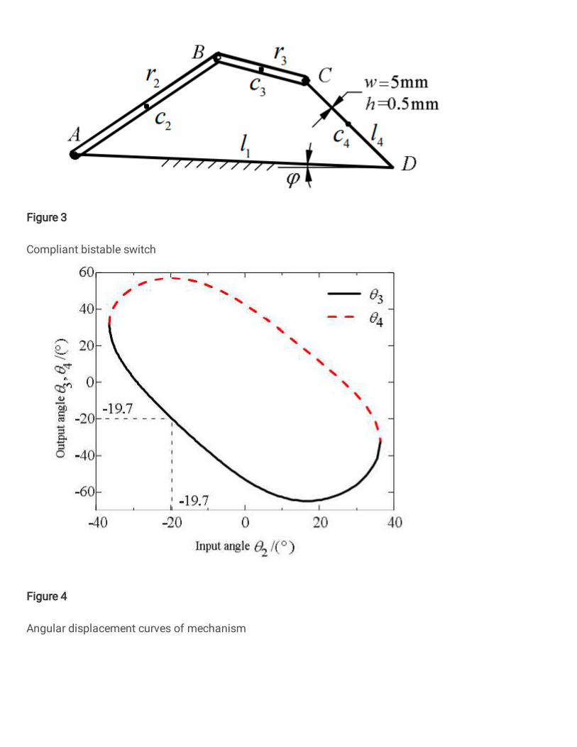
Figure 3
Compliant bistable switch
Figure 4
Angular displacement curves of mechanism

Figure 5
Relation curve of Tin and θ40
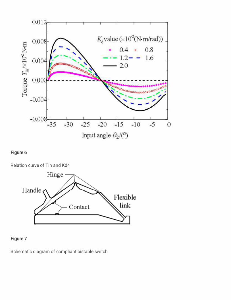
Figure 6
Relation curve of Tin and Kd4
Figure 7
Schematic diagram of compliant bistable switch
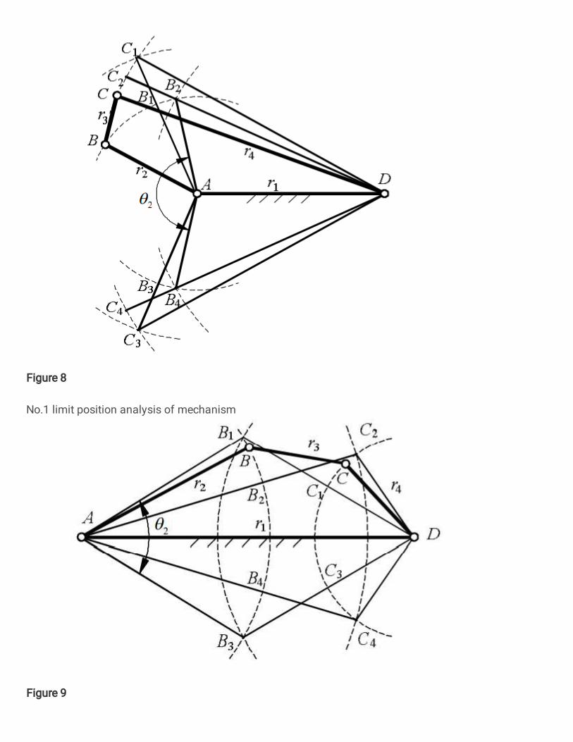
Figure 8
No.1 limit position analysis of mechanism
Figure 9
No.2 limit position analysis of mechanism
Figure 10
No.3 limit position analysis of mechanism
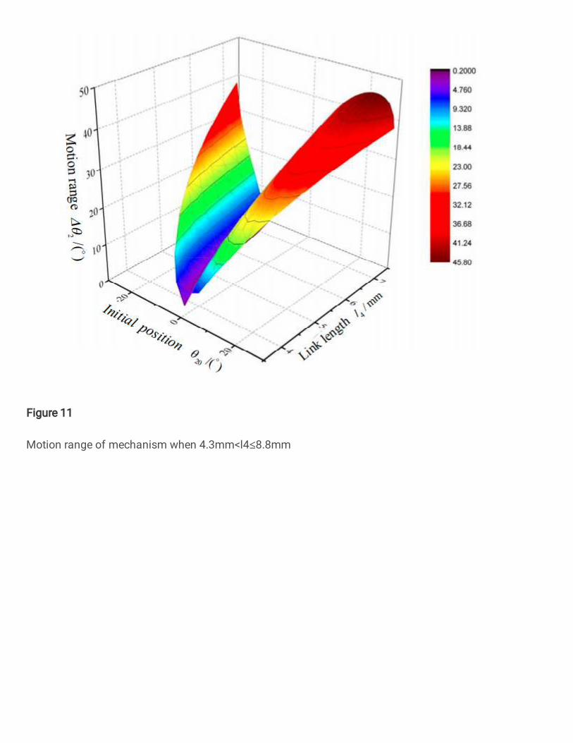
Figure 11
Motion range of mechanism when 4.3mm<l4≤8.8mm
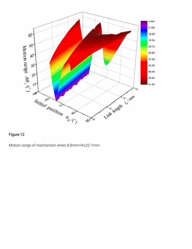
Figure 12
Motion range of mechanism when 8.8mm<l4≤22.1mm
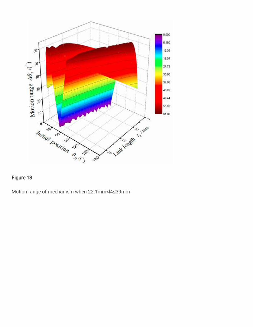
Figure 13
Motion range of mechanism when 22.1mm<l4≤39mm

Figure 14
Motion range of mechanism when 39mm<l4≤56.9mm