chapter4 review and analysis of apollo 13...
TRANSCRIPT
CHAPTER4
REVIEW AND ANALYSIS OF APOLLO 13 ACCIDENT
PART 1. INTRODUCTION
It became clear in the course of the Board's review that the acci- dent during the Apollo 13 mission was initiated in the service module cryogenic oxygen tank no. 2. Therefore, the following analysis centers on that tank and its history. In addition, the recovery steps taken in the period beginning with the accident and continuing to reentry are discussed.
Two oxygen tanks essentially identical to oxygen tank no. 2 on Apollo 13, and two hydrogen tanks of similar design, operated satisfac- torily on several unmanned Apollo flights and on the Apollo 7, 8, 9, 10, 11, and 12 manned missions. With this in mind, the Board placed particu- lar emphasis on each difference in the history of oxygen tank no. 2 from the history of the earlier tanks, in addition to reviewing the design, assembly, and test history.
4-1

PART 2. OXYGEN TANK NO. 2 HISTORY
DESIGN
On February 26, 1966, the North American Aviation Corporation, now North American Rockwell (NR), prime contractor for the Apollo command and service modules (CSM), awarded a subcontract to the Beech Aircraft Corporation (Beech) to design, develop, fabricate, assemble, test, and deliver the Block II Apollo cryogenic gas storage subsystem. This was a follow-on to an earlier subcontract under which the somewhat different Block I subsystem was procured.
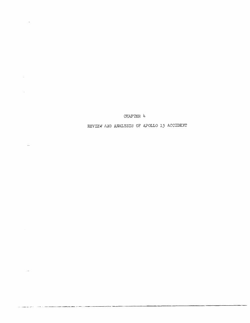
As the simplified drawing in figure 4-l indicates, each oxygen tank has an outer shell and an inner shell, arranged to provide a vacuum space to reduce heat leak, and a dome enclosing paths into the tank for transmission of fluids and electrical power and signals. The space be- tween the shells and the space in the dome are filled with insulating materials. Mounted in the tank are two tubular assemblies. One, called the heater tube, contains two thermostatically protected heater coils and two small fans driven by 1800 rpm motors to stir the tank contents. The other, called the quantity probe, consists of an upper section which supports a cylindrical capacitance gage used to measure electrically the quantity of fluid in the tank. The inner cylinder of this probe serves both as a fill and drain tube and as one plate of the capacitance gage. In addition, a temperature sensor is mounted on the outside of the quan- tity probe near the head. Wiring for the gage, the temperature sensor, the fan motors, and the heaters passes through the head of the quantity probe to a conduit in the dome. From there the wiring runs to a con- necter which ties it electrically to the appropriate external circuits in the CSM. The routing of wiring and lines from the tank through the dome is shown in figure 4-2.
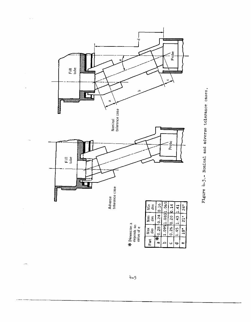
As shown in figure 4-2, the fill line from the exterior of the SM enters the oxygen tank and connects to the inner cylinder of the capaci- tance gage through a coupling of two Teflon adapters or sleeves and a short length of Inconel tubing. The dimensions and tolerances selected are such that if "worst case" variations in an actual system were to occur, the coupling might not reach from the fill line to the gage cylin- der (fig. 4-3). Thus, the variations might be such that a very loose fit would result.
The supply line from the tank leads from the head of the quantity probe to the dome and thence, after passing around the tank between the inner and outer shells, exits through the dome to supply oxygen to the fuel cells in the service module (SM) and the environmental control system (ECS) in the command module (CM). The supply line also connects
4-2
SWPlY line -
To fuel ccl I/ ECS
i
Pressure transducer
Blowout disc
~oseou’ cap
a Capacitance
I IIs
gP .-
“3: ‘:
switch
i
Relief valve
Closeout cap
J L Overboard
Figure 4-l.- Oxygen tank no. 2 internal components.
4-3
~_ .__-.- -.. , __- .-.. - _. _-.---,..-_. _ _. ___- . _ ^ ..~. _.^ I . ..-..- . ..-.- ,x _ ..^-.._--.

. . ^ ^^Y^^..
I- liter
Quantity probe -
To fan 1
Figure 4-2.- Oxygen tank wiring and lines.
4-4

r I
-
4-5
.
.-
4-5
to a relief valve. Under normal conditions , pressure in the tank is measured by a pressure gage in the supply line and a pressure switch near this gage is provided to turn on the heaters in the oxygen tank if the pressure drops below a preselected value. This periodic addition of heat to the tank maintains the pressure at a sufficient level to satisfy the demand for oxygen as tank quantity decreases during a flight mission.
The oxygen tank is designed for a capacity of 320 pounds of super- critical oxygen at pressures ranging between 865 to 935 pounds per square inch absolute (psia). The tank is initially filled with liquid oxygen at -297" F and operates over the range from -340° F to +80’ F. The term "supercritical" means that the oxygen is maintained at a temper- ature and pressure which assures that it is a homogeneous, single-phase fluid.
The burst pressure of the oxygen tank is about 2200 psi at -150° F, over twice the normal operating pressure at that temperature. The relief valve is designed to relieve pressure in the oxygen tank overboard at a pressure of approximately 1000 psi. The oxygen tank dome is open to the vacuum between the inner and outer tank shell and contains a rupture disc designed to blow out at about 75 psi.
The approximate amounts of principal materials within the oxygen tank are set forth in table 4-I.
TABLE 4-I.- MATERIALS WITHIN OXYGEN TANK
s
Material
Teflon-wire insulation sleeving and solid
Aluminum (all forms)
Stainless steel
Inconel alloys
Approximate Available quantity, lb energy, Btu
1.1 2,400
0.8 20,500
2.4 15,000
1.7 2,900
Two oxygen tanks are mounted on a shelf in bay 4 of the SM, as . - hewn in figure 4-4. Figures 4-5 through 4-B are photographs of portions
4-6
Oxygen subsystem
b tank 1
Figure 4-b.- Arrangement of fuel cells and cryogenic systems in bay 4.
4-7
This page left blank intentionally.
4-8

Figure 4-5. - Fuel cells shelf.
4-9/4-10
Figure 4-6.- Oxygen tank shelf.
4-n/4-12
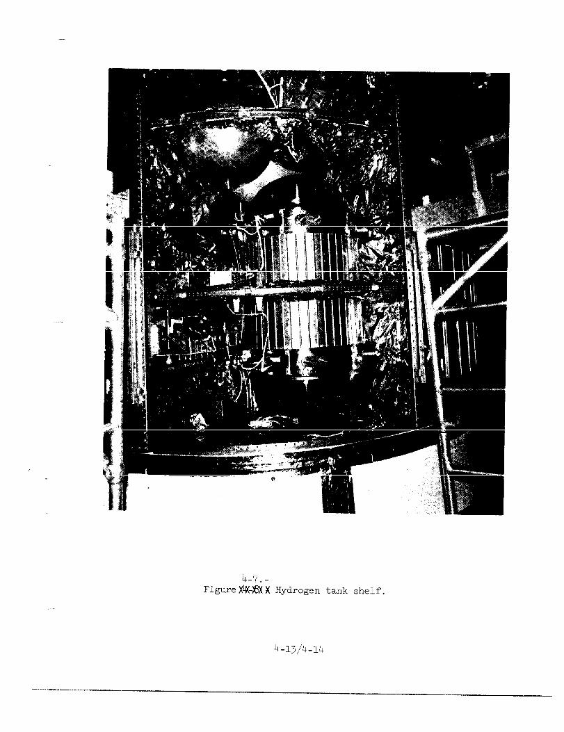
4-7.- FigureX#jjXX Hydrogen tank shelf.
4-13/4-14
-
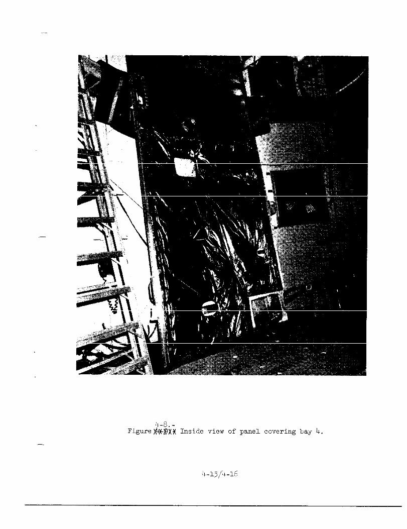
4-8. - Figure$t)@Xj( Inside view of panel covering bay 4.
-
4-15/4-16
of the Apollo 13 service module (SM 109) at the North American Rockwell plant prior to shipment to KSC. Figure 4-5 shows the fuel cell shelf, with fuel cell 1 on the right, fuel cell 3 on the left, and fuel cell 2 behind cells 1 and 3. 'The top of oxygen tank no. 2 can be seen at the lower left. Figure 4-6 shows the oxygen tank shelf, with oxygen tank no. 2 at left center. Figure 4-7 shows the hydrogen tank shelf with hydrogen tank no. 1 on top and hydrogen tank no. 2 below. The bottom of the oxygen shelf shows some of the oxygen system instrumentation and wiring, largely covered by insulation. Figure 4-8 is a photograph of the bay 4 panel, which was missing from the service module after the accident.
A more detailed description of the oxygen tank design is contained in Appendix D to this report.
MANUFACTURE
The manufacture of oxygen tank no. 2 began in 1966. Under subcon- tracts with Beech, the inner shell of the tank was manufactured by the Airite Products Division of Electrada Corporation; the quantity probe was made by Simmonds Precision Products, Inc.; and the fans and fan motors were produced by Globe Industries, Inc.
The Beech serial number assigned to the oxygen tank no. 2 flown in the Apollo 13 was 10024XTAOOO8. It was the eighth Block II oxygen tank built. Twenty-eight Block I oxygen tanks had previously been built by Beech.
The design of the oxygen tank is such that once the upper and lower halves of the inner and outer shells are assembled and welded, the heater assembly must be inserted in the tank, moved to one side, and bolted in place. Then the quantity probe is inserted into the tank and the heater assembly wires (to the heaters, the thermostats, and the fan motors) must be pulled through the head of the quantity probe and the 32-inch coiled conduit in the dome. Thus, the design requires during assembly a substantial amount of wire movement inside the tank, where movement cannot be readily observed, and where possible damage to wire insulation by scraping or flexing cannot be easily detected before the tank is capped off and welded closed.
Several minor manufacturing flaws were discovered in oxygen tank no. 2 in the course of testing. A porosity in a weld on the lower half of the outer shell necessitated grinding and rewelding. Rewelding was also required when it was determined that incorrect welding wire had been inadvertently used for a small weld on a vacuum pump mounted on
4-17
the outside of the tank dome. The upper fan motor originally installed was noisy and drew excessive current. The tank was disassembled and the heater assembly, fans, and heaters were replaced with a new assembly and new fans. The tank was then assembled and sealed for the second time, and the space between the inner and outer shells was pumped down over a 28-day period to create the necessary vacuum.
TANK TESTS AT BEECH
Acceptance testing of oxygen tank no. 2 at Beech included extensive dielectric, insulation, and functional tests of heaters, fans, and vac- ion pumps. The tank was then leak tested at 500 psi and proof tested at 1335 psi with helium.
After the helium proof test, the tank was filled with liquid oxygen and pressurized to a proof pressure of 1335 psi by use of the tank heaters powered by 65 V Etc. Extensive heat-leak tests were run at 900 psi for 25 to 30 hours over a range of ambient conditions and out- flow rates. At the conclusion of the heat-leak tests, about 100 pounds of oxygen remained in the tank. About three-fourths of this was released by venting the tank at a controlled rate through the supply line to about 20 psi. The tank was then emptied by applying warm gas at about 30 psi to the vent line to force the liquid oxygen (LOX) in the tank out the fill line (see fig. h-2). No difficulties were recorded in this detanking operation.
The acceptance test indicated that the rate of heat leak into the tank was higher than permitted by the specifications. After some re- working, the rate improved, but was still somewhat higher than specified. The tank was accepted with a formal waiver of this condition. Several other minor discrepancies were also accepted. These included oversized holes in the support for the electrical plug in the tank dome, and an oversized rivet hole in the heater assembly just above the lower fan. None of these items were serious, and the tank was accepted, filled with helium at 5 psi, and shipped to NR on May 3, 1967.
ASSEMBLY AND TEST AT NORTH AMERICAN ROCKWELL
The assembly of oxygen shelf serial number 0632AAG3277, with Beech oxygen tank serial number 10024XTAOOOg as oxygen tank no. 1 and serial number 10024XTAOOO8 as oxygen tank no. 2, was completed on March 11, 1968. The shelf was to be installed in SM 106 for flight in the Apollo 10 mission.
4-18
_. .__. .__. ._.__ ..I__ _,_---I_ . ..I_.j-___ll-----..--.__l_l -.,- --.----
Beginning on April 27, the assembled oxygen shelf underwent stand- ard proof-pressure, leak, and functional checks. One valve on the shelf leaked and was repaired, but no anomalies were noted with regard to oxygen tank no. 2, and therefore no rework of oxygen tank no. 2 was required. None of the oxygen tank testing at NR requires use of LOX in the tanks.
On June 4, 1968, the shelf was installed in SM 106.
Between August 3 and August 8, 1968, testing of the shelf in the SM was conducted. No anomalies were noted.
Due to electromagnetic interference problems with the vat-ion pumps on cryogenic tank domes in earlier Apollo spacecraft, a modifica- tion was introduced and a decision was made to replace the complete oxygen shelf in SM 106. An oxygen shelf with approved modifications was prepared for installation in SM 106. On October 21, 1968, the oxygen shelf was removed from SM 106 for the required modification and instal- lation in a later spacecraft.
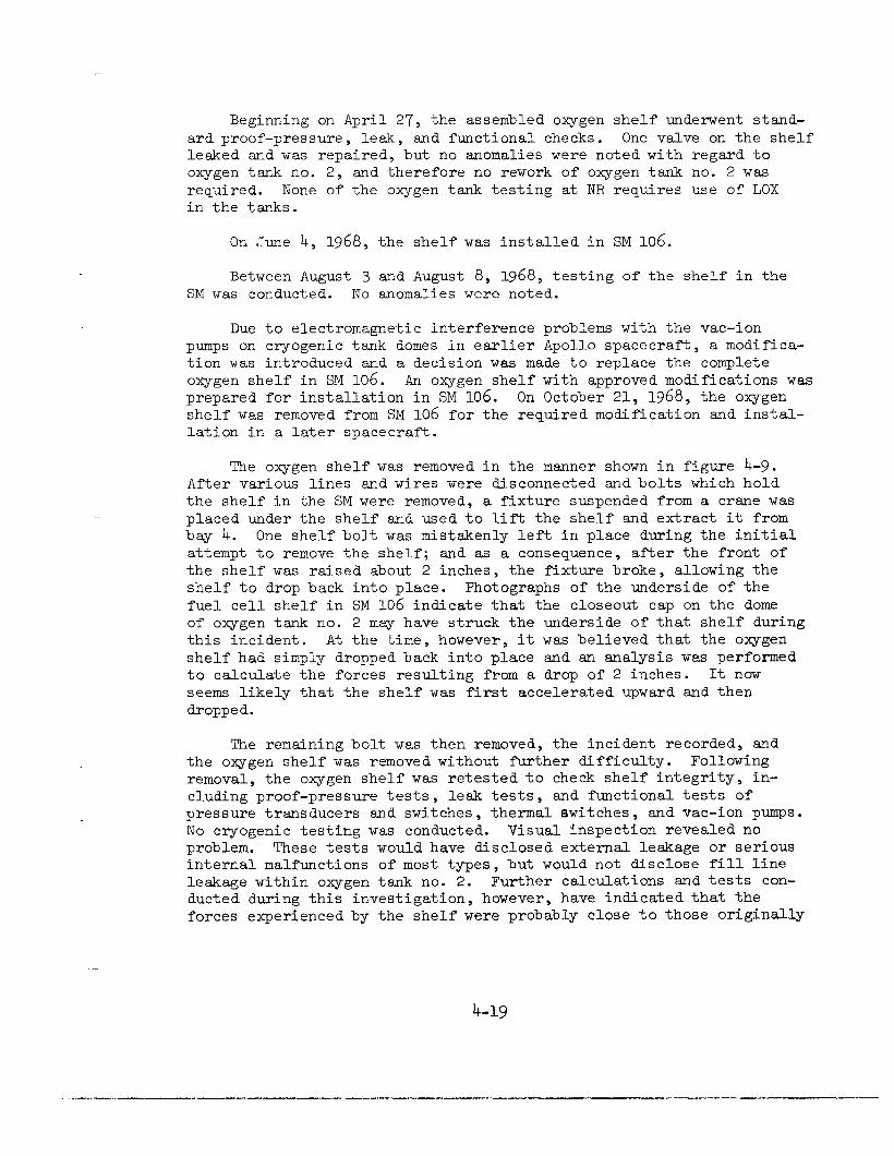
The oxygen shelf was removed in the manner shown in figure 4-9. After various lines and wires were disconnected and bolts which hold the shelf in the SM were removed, a fixture suspended from a crane was placed under the shelf and used to lift the shelf and extract it from bay 4. One shelf bolt was mistakenly left in place during the initial attempt to remove the shelf; and as a consequence, after the front of the shelf was raised about 2 inches, the fixture broke, allowing the shelf to drop back into place. Photographs of the underside of the fuel cell shelf in SM 106 indicate that the closeout cap on the dome of oxygen tank no. 2 may have struck the underside of that shelf during this incident. At the time, however, it was believed that the oxygen shelf had simply dropped back into place and an analysis was performed to calculate the forces resulting from a drop of 2 inches. It now seems likely that the shelf was first accelerated upward and then dropped.
The remaining bolt was then removed, the incident recorded, and the oxygen shelf was removed without further difficulty. Following removal, the oxygen shelf was retested to check shelf integrity, in- cluding proof-pressure tests, leak tests, and functional tests of pressure transducers and switches, thermal switches, and vat-ion pumps. No cryogenic testing was conducted. Visual inspection revealed no problem. These tests would have disclosed external leakage or serious internal malfunctions of most types, but would not disclose fill line leakage within oxygen tank no. 2. Further calculations and tests con- ducted during this investigation, however, have indicated that the forces experienced by the shelf were probably close to those originally
4-19
I -- - -
4-20

calculated assuming a 2-inch drop only. The probability of tank damage from this incident, therefore, is now considered to be rather low, although it is possible that a loosely fitting fill tube could have been displaced by the event.
The shelf passed these tests and was installed in SM 109 on November 22, 1968. The shelf tests accomplished earlier in SM 106 were repeated in SM 109 in late December and early January, with no significant problems, and SM 109 was shipped to Kennedy Space Center (KSC) in June of 1969 for further testing, assembly on the launch vehicle, and launch.
TESTING AT KSC
At the Kennedy Space Center the CM and the SM were mated, checked, assembled on the Saturn V launch vehicle, and the total vehicle was moved to the launch pad.
The countdown demonstration test (CDDT) began on March 16, 1970. Up to this point, nothing unusual about oxygen tank no. 2 had been noted during the extensive testing at KSC. The oxygen tanks were evacuated to 5mm Hg followed by an oxygen pressure of about 80 psi. After the cooling of the fuel cells, cryogenic oxygen loading and tank pressurization to 331 psi were completed without abnormalities. At the time during CDDT when the oxygen tanks are normally partially emptied to about 50 percent of capacity, oxygen tank no. lbehaved normally, but oxygen tank no. 2 only went down to 92 percent of its capacity. The normal procedure during CDDT to reduce the quantity in the tank is to apply gaseous oxygen at 80 psi through the vent line and to open the fill line. When this procedure failed, it was decided to proceed with the CDDT until completion and then look at the oxygen detanking problem in detail. An Interim Discrepancy Report was written and transferred to a Ground Support Equipment (GSE) Discrepancy Report, since a GSE filter was suspected.
On Friday, March 27, 1970, detanking operations were resumed, after discussions of the problem had been held with KSC, MSC, NR, and Beech personnel participating, either personally or by telephone. As a first
step, oxygen tank no. 2, which had self-pressurized to 178 psi and was about 83 percent full, was vented through its fill line. The quantity decreased to 65 percent. Further discussions between KSC, MSC, NR, and Beech personnel considered that the problem might be due to a leak in the path between the fill line and the quantity probe due to loose fit in the sleeves and tube. Referring to figure 4-2, it will be noted that such a leak would allow the gaseous oxygen (GOX) being supplied to the vent line to leak directly to the fill line without forcing any
4-21
significant amount of LOX out of the tank. At this point, a discrep- ancy report against the spacecraft system was written.
A "normal" detanking procedure was then conducted on both oxygen tanks, pressurizing through the vent line and opening the fill lines. Tank no. 1 emptied in a few minutes. Tank no. 2 did not. Additional attempts were made with higher pressures without effect, and a decision was made to try to "boil off" the remaining oxygen in tank no. 2 by use of the tank heaters. The heaters were energized with the 65 V dc. GSE power supply, and, about l-1/2 hours later, the fans were turned on to add more heat and mixing. After 6 hours of heater operation, the quantity had only decreased to 35 percent, and it was decided to attempt a pressure cycling technique. With the heaters and fans still energized, the tank was pressurized to about 300 psi, held for a few minutes, and then vented through the fill line. The first cycle produced a 'I-percent quantity decrease, and the process was continued, with the tank emptied after five pressure/vent cycles. The fans and heaters were turned off after about 8 hours of heater operation.
Suspecting the loosely fitting fill line connection to the quantity probe inner cylinder, KSC personnel consulted with cognizant personnel at MSC and at NR and decided to test whether the oxygen tank no. 2 could be filled without problems. It was decided that if the tank could be filled, the leak in the fill line would not be a problem in flight, since it was felt that even a loose tube resulting in an electrical short between the capacitance plates of the quantity gage would result in an energy level too low to cause any other damage.
Replacement of the oxygen shelf in the CM would have been difficult and would have taken at least 45 hours. In addition, shelf replacement would have had the potential of damaging or degrading other elements of the SM in the course of replacement activity. Therefore, the decision was made to test the ability to fill oxygen tank no. 2 on March 30, 1970, twelve days prior to the scheduled Saturday, April 11, launch, so as to be in a position to decide on shelf replacement well before the launch date.
Accordingly, flow tests with GOX were run on oxygen tank no. 2 and on oxygen tank no. 1 for comparison. No problems were encountered, and the flow rates in the two tanks were similar. In addition, Beech was asked to test the electrical energy level reached in the event of a short circuit between plates of the quantity probe capacitance gage. This test showed that very low energy levels would result. On the filling test, oxygen tanks no. 1 and no. 2 were filled with LOX to about 20 percent of capacity on March 30 with no difficulty. Tank no. 1 emptied in the normal manner, but emptying oxygen tank no. 2 again required pressure cycling with the heaters turned on.
4-22
.._ _.... - . . . . . .----.-.- -.-"__~- -___~-.--I_-

As the launch date approached, the oxygen tank no. 2 detsnking problem was considered by the Apollo organization. At this point, the "shelf drop" incident on October 21, 1968, at NR was not considered and it was felt that the apparently normal de-tanking which had occurred in 1967 at Beech was not pertinent because it was believed that a different procedure was used by Beech. In fact, however, the last portion of the procedure was quite similar, although a slightly lower GOX pressure was utilized.
Throughout these considerations, which involved technical and management personnel of KSC, MSC, NR, Beech, and NASA Headquarters, emphasis was directed toward the possibility and consequences of a loose fill tube; very little attention was paid to the extended operation of heaters and fans except to note that they apparently operated during and after the detsnking sequences.
Many of the principals in the discussions were not aware of the extended heater operations. Those that did know the details of the procedure did not consider the possibility of damage due to excessive heat within the tank, and therefore did not advise management officials of any possible consequences of the unusually long heater operations.
As noted earlier in this chapter, and shown in figure 4-2, each heater is protected with a thermostatic switch, mounted on the heater tube, which is intended to open the heater circuit when it senses a temperature of 80' F. In tests conducted at MSC since the accident, however, it was found that the switches failed to open when the heaters were powered from a 65 V dc supply similar to the power used at KSC during the detanking sequence. Subsequent investigations have shown that the thermostatic switches used, while rated as satisfactory for the 28 V dc spacecraft power supply, could not open properly at 65 V dc. Qualification and test procedures for the heater assemblies and switches do not at any time test the capability of the switches to open while under full current conditions. A review of the voltage recordings made during the de-tanking at KSC indicates that, in fact, the switches did not open when the temperature indication from within the tank rose past 80' F. Further tests have shown that the tempera- tures on the heater tube may have reached as much as 1000° F during the de-tanking. This temperature will cause serious damage to adjacent Teflon insulation, and such damage almost certainly occurred.
None of the above, however, Fras known at the time and, after extensive consideration was given to all possibilities of damage from a loose fill tube, it was decided to leave the oxygen shelf and oxygen tank no. 2 in the SM and to proceed with preparations .for the launch of Apollo 13.
4-23
The manufacture and test history of oxygen tank no. 2 is discussed in more detail in Appendix C to this report.
4-24

PART 3. THE APOLLO 13 FLIGHT
The Apollo 13 mission was designed to perform the third manned lunar landing. The selected site was in the hilly uplands of the Fra Mauro formation. A package of five scientific experiments was planned for emplacement on the lunar surface near the lunar module (LM) landing point: (1) a 1 unar passive seismometer to measure and relay meteoroid impact and moonquakes and to serve as the second point in a seismic net begun with the Apollo 12 seismometer; (2) a heat flow device for measur- ing the heat flux from the lunar interior to the surface and surface material conductivity to a depth of 3 meters; (3) a charged-particle lunar environment experiment for measuring solar wind proton and electron effects on the lunar environment; (4) a cold cathode gage for measuring density and temperature variations in the lunar atmosphere; and (5) a dust detector experiment.
Additionally, the Apollo 13 landing crew was to gather the third set of selenological samples of the lunar surface for return to earth for extensive scientific analysis. Candidate future landing sites were scheduled to be photographed from lunar orbit with a high-resolution topographic camera carried aboard the command module.
During the week prior to launch, backup Lunar Module Pilot Charles M. Duke, Jr., contracted rubella. Blood tests were performed to deter- mine prime crew immunity, since Duke had been in close contact with the prime crew. These tests determined that prime Commander James A. Love11 and prime Lunar Module Pilot Fred Haise were immune to rubella, but that prime Command Module Pilot Thomas K. Mattingly III did not have immunity. Consequently, following 2 days of intensive simulator training at the Kennedy Space Center, backup Command Module Pilot John L. Swigert, Jr., was substituted in the prime crew to replace Mattingly. Swigert had trained for several months with the backup crew, and this additional work in the simulators was aimed toward integrating him into the prime crew so that the new combination of crewmen could function as a team during the mission.
Launch was on time at 2:l3 p.m., e.s.t., on April 11, 1970, from the KSC Launch Complex 39A. The spacecraft was inserted into a loo-nautical- mile circular earth orbit. The only significant launch phase anomaly was premature shutdown of the center engine of the S-II second stage. As a result, the remaining four S-II engines burned 34 seconds longer than planned and the S-IVB third stage burned a few seconds longer than plan- ned. At orbital insertion, the velocity was within 1.2 feet per second of the planned velocity. Moreover, an adequate propellant margin was maintained in the S-IVB for the translunar injection burn.
4-25

Orbital insertion was at 00:12:39 ground elapsed time (g.e.t.). The initial one and one-half earth orbits before translunar injection (TLI) were spent in spacecraft systems checkout and included television transmissions as Apollo 13 passed over the Merritt Island Launch Area, Florida, tracking station.
The S-IVB restarted at 02:35:46 g.e.t. for the translunar injection burn, with shutdown coming some 5 minutes 51 seconds later. Accuracy of the Saturn V instrument unit guidance for the TLI burn was such that a planned midcourse correction maneuver at 11:41:23 g.e.t, was not neces- sary. After TLI, Apollo 13 was calculated to be on a free-return trajec- tory with a predicted closest approach to the lunar surface of 210 nautical miles.
The CSM was separated from the S-IVB about 3 hours after launch, and after a brief period of stationkeeping, the crew maneuvered the CSM to dock with the LM vehicle in the LM adapter atop the S-IVB stage. The S-IVB stage was separated from the docked CSM and L&I shortly after 4 hours into the mission.
In manned lunar missions prior to Apollo 13, the spent S-IVB third stages were accelerated into solar orbit by a "slingshot" maneuver in which residual liquid oxygen was dumped through the J-2 engine to pro- vide propulsive energy. On Apollo 13, the plan was to impact the S-IVB stage on the lunar surface in proximity to the seismometer emplaced in the Ocean of Storms by the crew of Apollo 12.
Two hours after TLI, the S-IVB attitude thrusters were ground com- manded on to adjust the stage's trajectory toward the designated impact at latitude 3' S. by longitude 30' W. Actual impact was at latitude 2.4O S. by longitude 27.9' W.--74 nautical miles from the Apollo 12 seismometer and well within the desired range. Impact was at 77:56:40 g.e.t. Seismic signals relayed by the Apollo 12 seismometer as the 30,700-pound stage hit the Moon lasted almost 4 hours and provided lunar scientists with additional data on the structure of the Moon.
As in previous lunar missions, the Apollo 13 spacecraft was set up in the passive thermal control (PTC) mode which calls for a continuous roll rate of three longitudinal axis revolutions each hour. During crew rest periods and at other times in translunar and transearth coast when a stable attitude is not required, the spacecraft is placed in PTC to stabilize the thermal response by spacecraft structures and systems.
At 30:40:49 g.e.t., a midcourse correction maneuver was made using the service module propulsion system. The crew preparations for the burn and the burn itself were monitored by the Mission Control Center (MMC) at MSC by telemetered data and by television from the spacecraft. This midcourse correction maneuver was a 23.2 feet per second hybrid
4-26

transfer burn which took Apollo 13 off a free-return trajectory and placed it on a non-free-return trajectory. A similar trajectory had been flown on Apollo 12. The objective of leaving a free-return trajectory is to control the arrival time at the Moon to insure the proper lighting conditions at the landing site. Apollo 8, 10, and 11 flew a pure free- return trajectory until lunar orbit insertion. The Apollo 13 hybrid transfer maneuver lowered the predicted closest approach, or pericyn- thion, altitude at the Moon from 210 to 64 nautical miles.
From launch through the first 46 hours of the mission, the perform- ance of oxygen tank no. 2 was normal, so far as telemetered data and crew observations indicate. At 46:40:02, the crew turned on the fans in oxygen tank no. 2 as a routine operation. Within 3 seconds, the oxygen tank no. 2 quantity indication changed from a normal reading of about 82 percent full to an obviously incorrect reading "off-scale high," of over 100 percent. Analysis of the electrical wiring of the quantity gage shows that this erroneous reading could be caused by either a short cir- cuit or an open circuit in the gage wiring or a short circuit between the gage plates. Subsequent events indicated that a short was the more likely failure mode.
At 47:54:50 and at 51:07:44, the oxygen tank no. 2 fans were turned on again, with no apparent adverse effects. The quantity gage continued to read off-scale high.
Following a rest period, the Apollo 13 crew began preparations for activating and powering up the L&l for checkout. At 53:27 g.e.t., the Commander (CMR) and Lunar Module Pilot (LMP) were cleared to enter the LM to commence inflight inspection of the LM. Ground tests before launch had indicated the possibility of a high heat-leak rate in the LM descent stage supercritical helium tank. Crew verification of actual pressures found the helium pressure to be within normal limits. Supercritical helium is stored in the LM for pressurizing propellant tanks.
The I&l was powered down and preparations were underway to close the LM hatch and run through the presleep checklist when the accident in oxygen tank no. 2 occurred.
At 55:52:30 g.e.t., a master alarm on the CM caution and warning system alerted the crew to a low pressure indication in the cryogenic hydrogen tank no. 1. This tank had reached the low end of its normal operating pressure range several times previously during the flight. At 55:52:58, flight controllers in the MCC requested the crew to turn on the cryogenic system fans and heaters.
The Command Module Pilot (CMP) acknowledged the fan cycle request at 55:53:06 g.e.t., and data indicate that current was applied to the oxygen tank no. 2 fan motors at 55:53:20.
4-27
About l-1/2 minutes later, at 55:54:53.555, telemetry from the spacecraft was lost almost totally for 1.8 seconds. During the period of data loss, the caution and warning system alerted the crew to a low voltage condition on dc main bus B. At about the same time, the crew heard a loud "bang" and realized that a problem existed in the spacecraft.
The events between fan turnon at 55:53:20 and the time when the problem was evident to the crew and Mission Control are covered in some detail in Part 4 of this chapter, "Summary Analysis of the Accident." It is now clear that oxygen tank no. 2 or its associated tubing lost pressure integrity because of combustion within the tank, and that ef- fects of oxygen escaping from the tank caused the removal of the panel covering bay 4 and a relatively slow leak in oxygen tank no. 1 or its lines or valves. Photos of the SM taken by the crew later in the mis- sion show the panel missing, the fuel cells on the shelf above the oxygen shelf tilted, and the high-gain antenna damaged.
The resultant loss of oxygen made the fuel cells inoperative, leav- ing the CM with batteries normally used only during reentry as the sole power source and with only that oxygen contained in a surge tank and repressurization packages (used to repressurize the CM arter cabin vent- ing). The LM, therefore, became the only source of sufficient electri- cal power and oxygen to permit safe return of the crew to Earth,
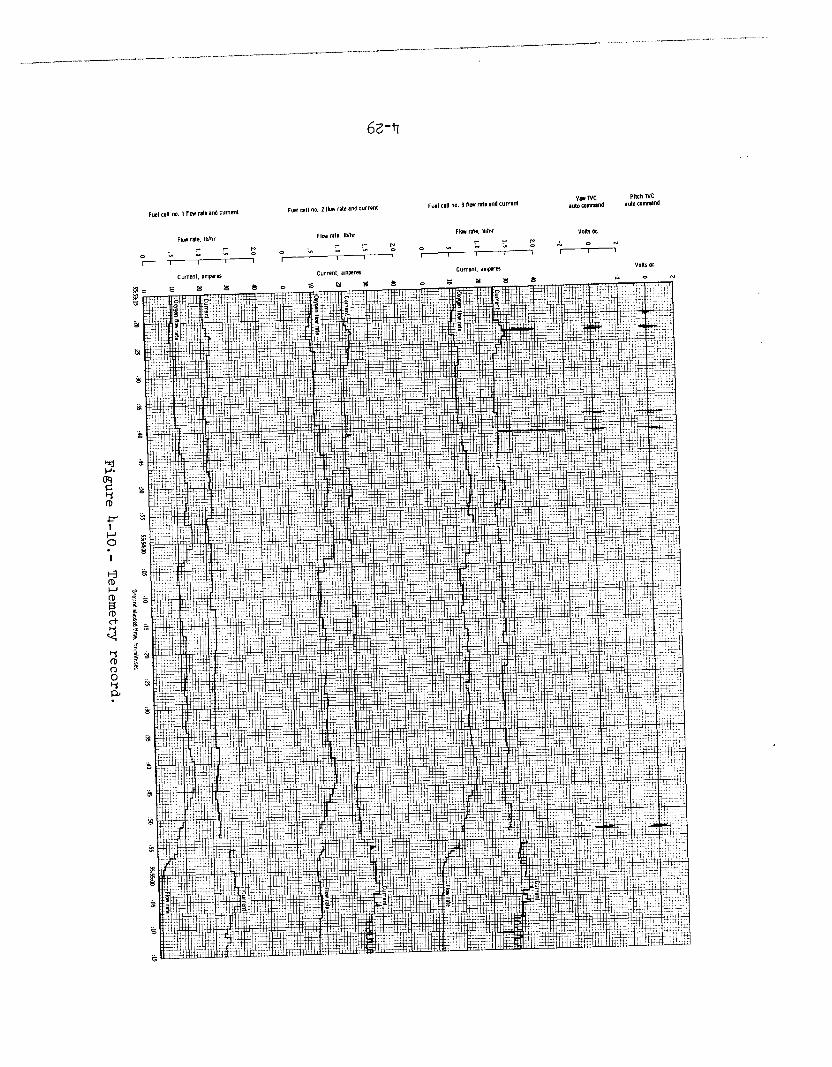
The various telemetered parameters of primary interest are shown in figure 4-10 and listed in table b-11.
4-28
~_-, . _ . . . . . _ - , . ^ . . _“~~ , . _ . . . . - . “ . . __ . . , , ; . -__. _” .__,___ - . - . . . _ - . . - . . I . _ - - . . . . - . . - _ - - _ - . - - . . . - . _ . . .~ . _ . - . - - . - , .
. - - . . I _ . , , _ I . . - ,_ -I.lsx
62-47

4-30
TABLE '+-II.- DETAILED CHRONOLOGY FROM 2.5 MINUTES BEFORE THE ACCIDENT TO 5 MINUTES AFTER THE ACCIDENT
Time, g.e.t. Event
Events During 52 Seconds Prior to First Observed Abnormality
55:52:31 Master caution and warning triggered by low hydrogen pressure in tank no. 1. Alarm is turned off after 4 seconds.
55:52:58 Ground requests tank stir.
55:53:06 Crew acknowledges tank stir.
55:53:18 Oxygen tank no. 1 fans on.
55:53:19 Oxygen tank no. 1 pressure decreases 8 psi.
55:53:20 Oxygen tank no. 2 fans turned on.
55:53:20 Stabilization control system electrical disturbance indicates a power transient.
55:53:21 Oxygen tank no. 2 pressure decreases 4 psi.
Abnormal Events During 90 Seconds Preceding the Accident
55:53:22.718
55:53:22.757
55:53:22.772
55:53:36
55:53:38.057
55:53:38.085
Stabilization control system electrical disturbance indicates a power transient.
1.2-volt decrease in ac bus 2 voltage.
11.1~amp rise in fuel cell 3 current for one sample.
Oxygen tank no. 2 pressure begins rise lasting for 24 seconds.
U-volt decrease in ac bus 2 voltage for one sample.
Stabilization control system electrical disturbance indicates a power transient.
4-31
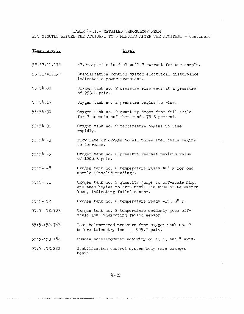
TABLE &II.- DETAILED CHRONOLOGY FROM 2.5 MINUTES BEFORE THE ACCIDENT TO 5 MINUTES AFTER THE ACCIDENT - Continued
Time, g.e.t. Event
55:53:41.172
55:53:41.192
22.9-amp rise in fuel cell 3 current for one sample.
Stabilization control system electrical disturbance indicates a power transient.
55:54:00 Oxygen tank no. 2 pressure rise ends at a pressure of 953.8 psia.
55:54:15
55:54:30
Oxygen tank no. 2 pressure begins to rise.
Oxygen tank no. 2 quantity drops from full scale for 2 seconds and then reads 75.3 percent.
55:54:31 Oxygen tank no. 2 temperature begins to rise rapidly.
55:54:43 Flow rate of oxygen to all three fuel cells begins to decrease.
55:54:45 Oxygen.tank no. 2 pressure reaches maximum value of 1008.3 psia.
55:54:48 Oxygen tank no. 2 temperature rises 40" F for one sample (invalid reading).
55:54:51
55:54:52
55:54:52.703
Oxygen tank no. 2 quantity jumps to off-scale high and then begins to drop until the time of telemetry loss, indicating failed sensor.
Oxygen tank no. 2 temperature reads -151.3' F.
55:54:52.763
Oxygen tank no. 2 temperature suddenly goes off- scale low, indicating failed sensor.
Last telemetered pressure from oxygen tank no. 2 before telemetry loss is 995.7 psia.
55:54:53.182 Sudden accelerometer activity on X, Y, and Z axes.
55:54:53.220 Stabilization control system body rate changes begin.
4-32
_ I . , . . “ , ___ __., . . . - _ -_ . . - . I .__I . . , _ . . “_^-_I -_. . . . _ . ._- -_ . . , - _._I _ _.^ . _ . . . ^ . _ . ‘ . - . - _ I ” _.l.--ll.lll*_,^_-“_lll_- . - - .
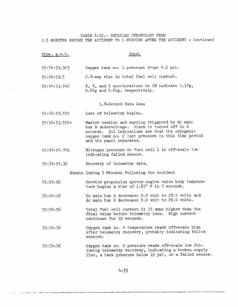
TABLE b-II.- DETAILED CHRONOLOGY FROM 2.5 MINUTES BEFORE THE ACCIDENT TO 5 MINUTES AFTER THE ACCIDENT - Continued
Time, g.e.t. Event
55:54:53.323 Oxygen tank no. 1 pressure drops 4.2 psi.
55:54:53.5 2.8~amp rise in total fuel cell current.
X, Y, and Z accelerations in CM indicate l.l7g, 0.65g aa 0.65g, respectively.
1.8-Second Data Loss
55:54:53.555 Loss of telemetry begins.
55:54:53*555+ Master caution and warning triggered by dc main bus B undervoltage. Alarm is turned off in 6 seconds. All indications are that the cryogenic oxygen tank no. 2 lost pressure in this time period and the panel separated.
55:54:54.741 Nitrogen pressure in fuel cell 1 is off-scale low indicating failed sensor.
55:54:55.35 Recovery of telemetry data.
Events During 5 Minutes Following the Accident
55:54:56 Service propulsion system engine valve body tempera- ture begins a rise of 1.65O F in 7 seconds.
55:54:56 DC main bus A decreases 0.9 volt to 28.5 volts and dc main bus B decreases 0.9 volt to 29.0 volts.
55:54:56 Total fuel cell current is 15 amps higher than the final value before telemetry loss. High current continues for 19 seconds.
55:54:56
55:54:56
Oxygen tank no. 2 temperature reads off-scale high after telemetry recovery, probably indicating failed sensors.
Oxygen tank no. 2 pressure reads off-scale low fol- lowing telemetry recovery, indicating a broken supply line, a tank pressure below 19 psi, or a failed sensor.
4-33
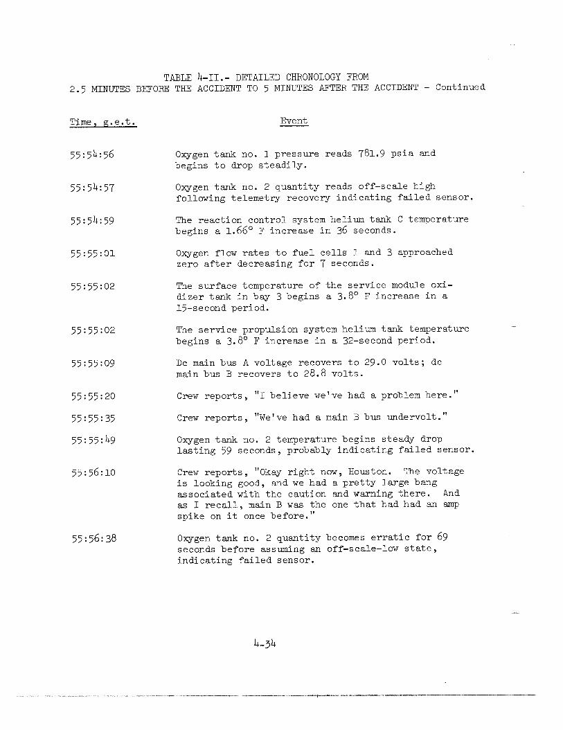
TABLE b-II.- DETAILED CHRONOLOGY FROM 2.5 MINUTES BEFORE THE ACCIDENT TO 5 MINUTES AFTER THE ACCIDENT - Continued
Time, g.e.t. Event
55:54:56 Oxygen tank no. 1 pressure reads 781.9 psia and begins to drop steadily.
55:54:57 Oxygen tank no. 2 quantity reads off-scale high following telemetry recovery indicating failed sensor.
55:54:59 The reaction control system helium tank C temperature begins a 1.66" F increase in 36 seconds.
55:55:01 Oxygen flow rates to fuel cells 1 and 3 approached zero after decreasing for 7 seconds.
55:55:02 The surface temperature of the service module oxi- dizer tank in bay 3 begins a 3.8' F increase in a 15-second period.
55:55:02 The service propulsion system helium tank temperature begins a 3.8O F increase in a 32-second period.
55:55:09 DC main bus A voltage recovers to 29.0 volts; dc main bus B recovers to 28.8 volts.
55:55:20 Crew reports, "I believe we've had a problem here."
55:55:35 Crew reports, "We've had a main B bus undervolt."
55:55:49 Oxygen tank no. 2 temperature begins steady drop lasting 59 seconds, probably indicating failed sensor.
55:56:10 Crew reports, "Okay right now, Houston. The voltage is looking good, and we had a pretty large bang associated with the caution and warning there. And as I recall, main B was the one that had had an amp spike on it once before."
55:56:38 Oxygen tank no. 2 quantity becomes erratic for 69 seconds before assuming an off-scale-low state, indicating failed sensor.
4-34

TABLE &II.- DETAILED CHRONOLOGY FROM 2.5 MINUTES BEFORE THE ACCIDENT TO 5 MINUTES AFTER THE ACCIDENT - Concluded
Time, g.e.t. Event
55: 57:04 Crew reports, "That jolt must have rocked the sensor on--see now--oxygen quantity 2. It was oscillating down around 20 to 60 percent. Now it's full-scale high again."
55:57:39
55:57:40
55:57:44
55:57:45
55:57:59
55:58:02
55:58:06
55:58:07 DC main bus A drops below 26.25 volts and in the next few seconds levels off at 25.5 volts.
55:58:07 Crew reports, rrac 2 is showing zip."
55:58:25 Crew reports, tlYes, we got a main bus A undervolt now, too, showing. It's reading about 25-l/2. Main B is reading zip right now."
56:00:06
Master caution and warning triggered by dc main bus B undervoltage. Alarm is turned off in 6 seconds.
DC main bus B drops below 26.25 volts and continues to fall rapidly.
AC bus 2 fails within 2 seconds
Fuel cell 3 fails.
Fuel cell 1 current begins to decrease.
Master caution and warning caused by ac bus 2 being reset. Alarm is turned off after 2 seconds.
Master caution and warning triggered by dc main bus A undervoltage. Alarm is turned off in 13 seconds.
Master caution and warning triggered by high hydrogen flow rate to fuel cell 2. Alarm is turned off in 2 seconds.
4-35
PART 4. SUMMARY ANALYSIS OF THE ACCIDENT
Combustion in oxygen tank no. 2 led to failure of that tank, damage to oxygen tank no. 1 or its lines or valves adjacent to tank no. 2, removal of the bay 4 panel and, through the resultant loss of all three fuel cells, to the decision to abort the Apollo 13 mission. In the attempt to determine the cause of ignition in oxygen tank no. 2, the course of propagation of the combustion, the mode of tank failure, and the way in which subsequent damage occurred, the Board has carefully sifted through all available evidence and examined the results of spe- cial tests and analyses conducted by the Apollo organization and by or for the Board after the accident. (For more information on details of mission events, design, manufacture and test of the system, and special tests and analyses conducted in this investigation, refer to Appendices B, C, D, E, and F of this report.)
Although tests and analyses are continuing, sufficient information is now available to provide a reasonably clear picture of the nature of the accident and the events which led up to it. It is now apparent that the extended heater operation at KSC damaged the insulation on wiring in the tank and thus made the wiring susceptible to the electrical short circuit which probably initiated combustion within the tank. While the exact point of initiation of combustion may never be known with cer- tainty, the nature of the occurrence is sufficiently understood to per- mit taking corrective steps to prevent its recurrence.
The Board has identified the most probable failure mode.
The following discussion treats the accident in its key phases: initiation , propagation of combustion, loss of oxygen tank no. 2 system integrity, and loss of oxygen tank no. 1 system integrity.
INITIATION
Key Data
55:53:20* Oxygen tank no. 2 fans turned on.
55:53:22.757 1.2-volt decrease in ac bus 2 voltage.
*In evaluating telemetry data, consideration must be given to the fact that the Apollo pulse code modulation (PCM) system samples data in time and quantitizes in amplitude. For further information, reference may be made to Part B7 of Appendix B.
4-36
^ “ . ._“_, ” - . . _ I - . - - - . _ “ . “ , . , “ . - _ - - * - - , . - . . - . . I -l_-_~~----_..-.~-~~-l.--~~.~
55:53:22.772 ll.l-ampere "spike" recorded in fuel cell 3 current followed by drop in current and rise in voltage typ- ical of removal of power from one fan motor--indicat- ing opening of motor circuit.
55:53:36 Oxygen tank no. 2 pressure begins to rise.
The evidence points strongly to an electrical short circuit with arcing as the initiating event. About 2.7 seconds after the fans were turned on in the SM oxygen tanks, an ll.l-ampere current spike and simultaneously a voltage-drop spike were recorded in the spacecraft electrical system. Immediately thereafter, current drawn from the fuel cells decreased by an amount consistent with the loss of power to one fan. No other changes in spacecraft power were being made at the time. No power was on the heaters in the tanks at the time and the quantity gage and temperature sensor are very low power devices. The next anom- alous event recorded was the beginning of a pressure rise in oxygen tank no. 2, 13 seconds later. Such a time lag is possible with low- level combustion at the time. These facts point to the likelihood that an electrical short circuit with arcing occurred in the fan motor or its leads to initiate the accident sequence. The energy available from the
short circuit was probably 10 to 20 joules. Tests conducted during this investigation have shown that this energy is more than ade- quate to ignite Teflon of the type contained within the tank. (The quantity gage in oxygen tank no. 2 had failed at 46:40 g.e.t. There is no evidence tying the quantity gage failure directly to accident initiation, particularly in view of the very low energy available from the gage.)
This likelihood of electrical initiation is enhanced by the high probability that the electrical wires within the tank were damaged dur- ing the abnormal detanking operation at KSC prior to launch.
Furthermore, there is no evidence pointing to any other mechanism of initiation.
PROPAGATION OF COMBUSTION
Key Data
55:53:36 Oxygen tank no. 2 pressure begins rise (same event noted previously).
55:53:38.057 U-volt decrease recorded in ac bus 2 voltage.
4-37
_--.. ._._ .--. _-.-. ..-. .-... - .--. _l_l- I^-li-.” ---,.- _*_I,___” .__..., “.~,_l.l_“- ..-.-. -..-..1.--_ -I~

55:53:41.172 22.9-ampere "spike" recorded in fuel cell 3 current, followed by drop in current and rise in voltage typ- ical of one fan motor -- indicating opening of another motor circuit.
55:54:00
55:54:15
55:54:30
Oxygen tank no. 2 pressure levels off at 954 psia.
Oxygen tank no. 2 pressure begins to rise again.
Oxygen tank no. 2 quantity gage reading drops from full scale (to which it had failed at 46:40 g.e.t.) to zero and then read 75-percent full. This behav- ior indicates the gage short circuit may have cor- rected itself.
55:54:31 Oxygen tank no, 2 temperature begins to rise rapidly.
55:54:45 Oxygen tank no. 2 pressure reading reaches maximum recorded value of 1008 psia.
55:54:52.763 Oxygen tank no. 2 pressure reading had dropped to 996 psia.
The available evidence points to a combustion process as the cause of the pressure and temperature increases recorded in oxygen tank no. 2. The pressure reading for oxygen tank no. 2 began to increase about 13 seconds after the first electrical spike, and about 55 seconds later the temperature began to increase. The temperature sensor reads local tem- perature, which need not represent bulk fluid temperature. Since the rate of pressure rise in the tank indicates a relatively slow propaga- tion of burning, it is likely that the region immediately around the temperature sensor did not become heated until this time.
There are materials within the tank that can, if ignited in the presence of supercritical oxygen, react chemically with the oxygen in exothermic chemical reactions. The most readily reactive is Teflon used for electrical insulation in the tank. Also potentially reactive are metals, particularly aluminum. There is more than sufficient Tef- lon in the tank, if reacted with oxygen, to account for the pressure and temperature increases recorded. Furthermore, the pressure rise took place over a period of more than 69 seconds, a relatively long period, and one which would be more likely characteristic of Teflon combustion than metal-oxygen reactions.
While the data available on the combustion of Teflon in supercrit- ical oxygen in zero-g are extremely limited, those which are available indicate that the rate of combustion is generally consistent with these
4-38
. - ” .__ I_ “ ,_ “ , . “ .__ . . x - - “ “ - - “ - - “ - . “ - - -1_._
~-

observations. The cause of the 15-second period of relatively constant pressure first indicated at 55:53:59.763 has not been precisely deter- mined; it is believed to be associated with a change in reaction rate as combustion proceeded through various Teflon elements.
While there is enough electrical power in the tank to cause ignition in the event of a short circuit or abnormal heating in defective wire, there is not sufficient electric power to account for all of the energy required to produce the observed pressure rise.
LOSS OF OXYGEN TANK NO. 2 SYSTEM II'JTEGRITY
Key Data
55:54:52 Last valid temperature indication (-151" F) from oxygen tank no. 2.
55:54:52.763 Last pressure reading from oxygen tank no. 2 before loss of data--996 psia.
55:54:53.182 Sudden accelerometer activity on X, Y, and Z axes.
55:54:53.220 Stabilization control system body rate changes begin.
55:54:53.555* Loss of telemetry data begins.
55:54:55.35 Recovery of telemetry data.
55:54:56 Various temperature indications in SM begin slight rises.
55:54:56 Oxygen tank no. 2 temperature reads off-scale high.
55:54:56 Oxygen tank no. 2 pressure reads off-scale low.
After the relatively slow propagation process described above took place, there wa.s a relatively abrupt loss of oxygen tank no. 2 integ- rity. About 69 seconds after the pressure began to rise, it reached the peak recorded, 1008 psia, the pressure at which the cryogenic oxygen tank relief valve is designed to be fully open. Pressure began a decrease for 8 seconds, dropping to 996 psia before readings were lost. Virtually
*Several bits of data have been obtained from this "loss of teleme- try data" period.
4-39
all signals from the spacecraft were lost about 1.85 seconds after the last presumably valid reading from within the tank, a temperature read- ing, and 0.8 second after the last presumably valid pressure reading (which may or may not reflect the pressure within the tank itself since the pressure transducer is about 20 feet of tubing length distant). Abnormal spacecraft accelerations were recorded approximately 0.42 sec- ond after the last pressure reading and approximately 0.38 second before the loss of signal. These facts all point to a relatively sudden loss of integrity. At about this time, several solenoid valves, including the oxygen valves feeding two of the three fuel cells, were shocked to the closed position. The "bang" reported by the crew also probably occurred in this time period. Telemetry signals from Apollo 13 were lost fox a period of 1.8 seconds. When signal was reacquired, all instru- ment indicators from oxygen tank no. 2 were off-scale, high or low. Tem- peratures recorded by sensors in several different locations in the SM showed slight increases in the several seconds following reacquisition of signal. Photographs taken later by the Apollo 13 crew as the SM was jettisoned show that the bay 4 panel was ejected, undoubtedly during this event.
Data are not adequate to determine precisely the way in which the oxygen tank no. 2 system lost its integrity. However, available infor- mation, analyses, and tests performed during this investigation indicate that most probably the combustion within the pressure vessel ultimately led to localized heating and failure at the pressure vessel closure. It is at this point, the upper end of the quantity probe, that the l/2-inch Inconel conduit is located, through which the Teflon-insulated wires enter the pressure vessel. It is likely that the combustion progressed along the wire insulation and reached this location where all of the wires come together. This , possibly augmented by ignition of the metal in the upper end of the probe, led to weakening and failure of the closure or the conduit, or both.
Failure at this point would lead immediately to pressurization of the tank dome, which is equipped with a rupture disc rated at about 75 psi. Rupture of this disc or of the entire dome would then release oxygen, accompanied by combustion products, into bay 4. The a~ccelera- tions recorded were probably caused by this release.
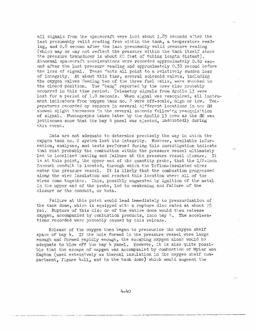
Release of the oxygen then began to pressurize the oxygen shelf space of bay 4. If the hole formed in the pressure vessel were large enough and formed rapidly enough, the escaping oxygen alone would be adequate to blow off the bay 4 panel. However, it is also quite possi- ble that the escape of oxygen was accompanied by combustion of Mylar and Kapton (used extensively as thermal insulation in the oxygen shelf com- partment, figure 4-11, and in the tank dome) which would augment the
4-40
4-n.- Figure X&-FXX Closeup view of oxygen tank shelf.
4-4114-42
pressure caused by the oxygen itself. The slight temperature increases recorded at various SM locations indicate that combustion external to the tank probably took place. Further testing may shed additional light on the exact mechanism of panel ejection. The ejected panel then struck the high-gain antenna, disrupting communications from the spacecraft for the 1.8 seconds.
LOSS OF OXYGEN TANK NO. 1 INTEGRITY
Key Data
55:54:53.323 Oxygen tank no. 1 pressure drops 4 psia (from 883 psia to 879 psia).
55:54:53.555 to Loss of telemetry data.
55:54:55.35
55: 54:56 Oxygen tank no. 1 pressure reads 782 psia and drops steadily. Pressure drops over a period of 130 min- utes to the point at which it was insufficient to sustain operation of fuel cell no. 2.
There is no clear evidence of abnormal behavior associated with oxygen tank no. 1 prior to loss of signal, although the one data bit (4 psi) drop in pressure in the last tank no. 1 pressure reading prior to loss of signal may indicate that a problem was beginning. Immediately after signal strength was regained, data show that tank no. 1 system had lost its integrity. Pressure decreases were recorded over a period of approximately 130 minutes, indicating that a relatively slow leak had developed in the tank no. 1 system. Analysis has indicated that the leak rate is less than that which would result from a completely rup- tured line, but could be consistent with a partial line rupture or a leaking check or relief valve.
Since there is no evidence that there was any anomalous condition arising within oxygen tank no. 1, it is presumed that the loss of oxygen tank no. 1 integrity resulted from the oxygen tank no. 2 system failure. The relatively sudden, and possibly violent, event associated with loss of integrity of the oxygen tank no. 2 system could have ruptured a line to oxygen tank no. 1, or have caused a valve to leak because of mechani- cal shock.
4-43

PART 5. APOLLO 13 RECOVERY
UNDERSTANDING THE PROBLEM
In the period immediately following the caution and warning alarm for main bus B undervoltage, and the associated "bang" reported by the crew, the cause of the difficulty and the degree of its seriousness were not apparent.
The 1.8-second loss of telemetered data was accompanied by the switching of the CSM high-gain antenna mounted on the SM adjacent to bay 4 from narrow beam width to wide beam width. The high-gain antenna does this automatically 200 milliseconds after its directional lock on the ground signal has been lost.
A confusing factor was the repeated firings of various SM attitude control thrusters during the period after data loss. In all probability, these thrusters were being fired to overcome the effects that oxygen venting and panel blowoff were having on spacecraft attitude, but it was believed for a time that perhaps the thrusters were malfunctioning.
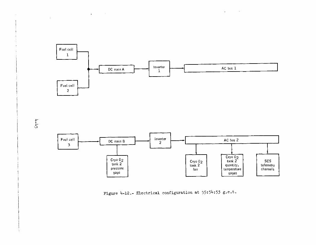
The failure of oxygen tank no. 2 and consequent removal of the bay 4 panel produced a shock which closed valves in the oxygen supply lines to fuel cells 1 and 3. These fuel cells ceased to provide power in about 3 minutes, when the supply of oxygen between the closed valves and the cells was depleted. Fuel cell 2 continued to power ac bus 1 through dc main bus A, but the failure of fuel cell 3 left dc main bus B and ac bus 2 unpowered (see fig. 4-12). The oxygen tank no. 2 temperature and quantity gages were connected to ac bus 2 at the time of the accident. Thus, these parameters could not be read once fuel cell 3 failed at 55:57:44 until power was applied to ac bus 2 from main bus A.
The crew was not alerted to closure of the oxygen feed valves to fuel cells 1 and 3 because the valve position indicators in the CM were arranged to give warning only if both the oxygen and hydrogen valves closed. The hydrogen valves remained open. The crew had not been alerted to the oxygen tank no. 2 pressure rise or to its subsequent drop because a hydrogen tank low pressure warning had blocked the cryogenic subsystem portion of the caution and warning system several minutes be- fore the accident.
When the crew heard the bang and got the master alarm for low dc main bus B voltage, the Commander was in the lower equipment bay of the command module, stowing a television camera which had just been in use.
4-44
._ _ ._..---. -.---__-1__ -.--- _.-.---.- II-IXI--.--.-l..-_---II.-. --.
AC bus 1
f J= ul
AC bus 2
I
Cry0 02 tank 2
pressure
gage
Figure 4-12.- Electrical configuration at 55:54:53 g.e.t.
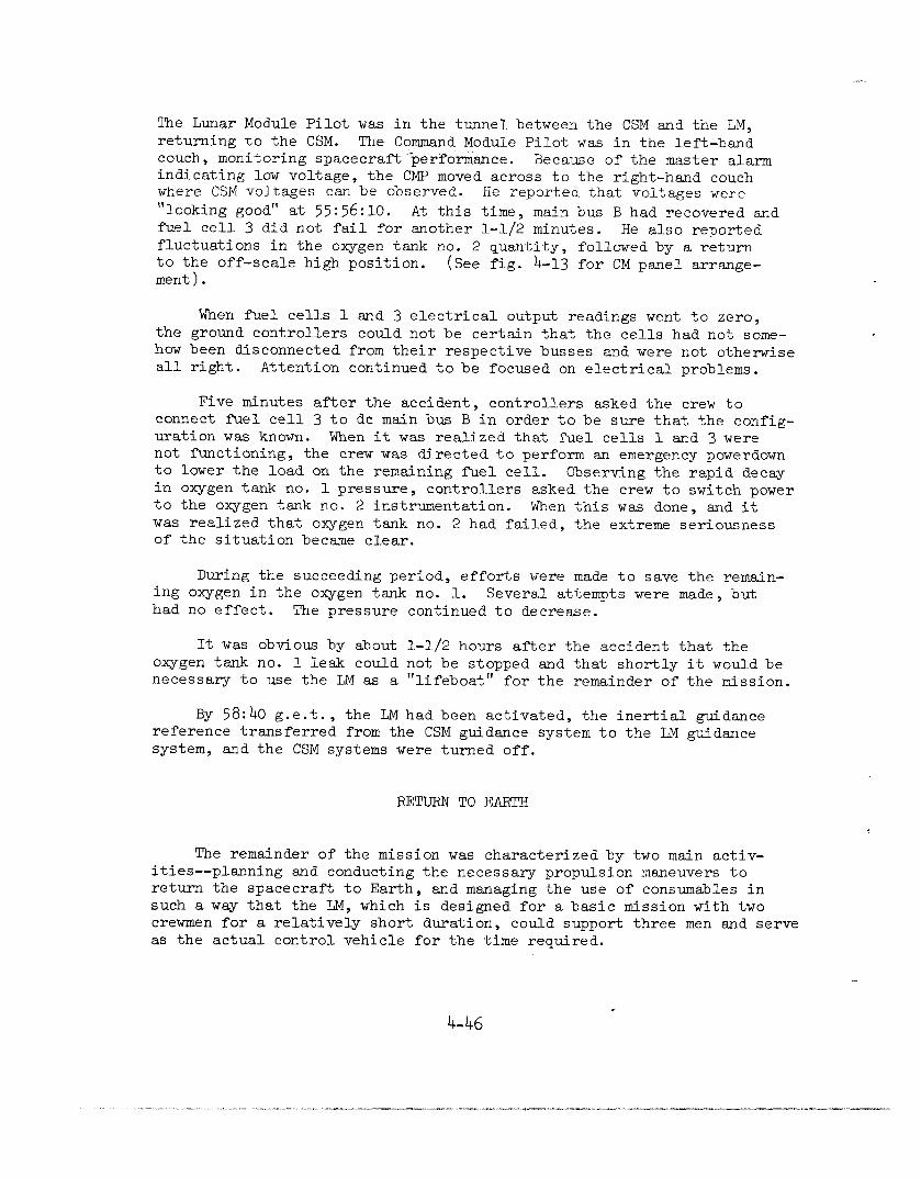
The Lunar Module Pilot was in the tunnel between the CSM and the LM, returning to the CSM. The Command Module Pilot was in the left-hand couch, monitoring spacecraft'3perfor&nce. Because of the master alarm indicating low voltage, the CMP moved across to the right-hand couch where CSM voltages can be observed. He reported that voltages were fllooking good" at 55:56:10. At this time, main bus B had recovered and fuel cell 3 did not fail for another l-1/2 minutes. He also reported fluctuations in the oxygen tank no. 2 quantity, followed by a return to the off-scale high position. ment).
(See fig. h-13 for CM panel arrange-
When fuel cells 1 and 3 electrical output readings went to zero, the ground controllers could not be certain that the cells had not some- how been disconnected from their respective busses and were not otherwise all right. Attention continued to be focused on electrical problems.
Five minutes after the accident, controllers asked the crew to connect fuel cell 3 to de main bus B in order to be sure that the config- uration was known. When it was realized that fuel cells 1 and 3 were not functioning, the crew was directed to perform an emergency powerdown to lower the load on the remaining fuel cell. Observing the rapid decay in oxygen tank no. 1 pressure, controllers asked the crew to switch power to the oxygen tank no. 2 instrumentation. When this was done, and it was realized that oxygen tank no. 2 had failed, the extreme seriousness of the situation became clear.
During the succeeding period, efforts were made to save the remain- ing oxygen in the oxygen tank no. 1. Several attempts were made, but had no effect. The pressure
It was obvious by about oxygen tank no. 1 leak could necessary to use the LM as a
continued to decrease.
l-1/2 hours after the accident that the not be stopped and that shortly it would be "lifeboat" for the remainder of the mission.
By 58:40 g.e.t., the LM had been activated, the inertial guidance reference transferred from the CSM guidance system to the LM guidance system, and the CSM systems were turned off.
RETURN TO EARTH
The remainder of the mission was characterized by two main activ- ities --planning and conducting the necessary propulsion maneuvers to return the spacecraft to Earth , and managing the use of consumables in such a way that the LM, which is designed for a basic mission with two crewmen for a relatively short duration, could support three men and serve as the actual control vehicle for the time required.
.
4-46
, , , . -
, . . _ . .___.._.I_ - . - . ___.__. ..__.~_..__ _ - . ^ I ” . . . . . - - -
I -

Gne significant anomaly was noted during the remainder of the mission. At about 97 hours 14 minutes into the mission, the LMP reported hearing a "thump" and observing venting from the LM. Subsequent data review shows that the LN electrical power system experienced a brief but major abnormal current flow at that time. There is no evidence that this anomaly was related to the accident. Analysis by the Apollo organization is continuing.
A number of propulsion options were developed and considered. It was necessary to return the spacecraft to a free-return trajectory and to make any required midcourse corrections. Normally, the service pro- pulsion system (SPS) in the SM would be used for such maneuvers. How- ever, because of the high electrical power requirements for using that engine, and in view of its uncertain condition and the uncertain nature of the structure of the SM after the accident, it was decided to use the LM descent engine if possible.
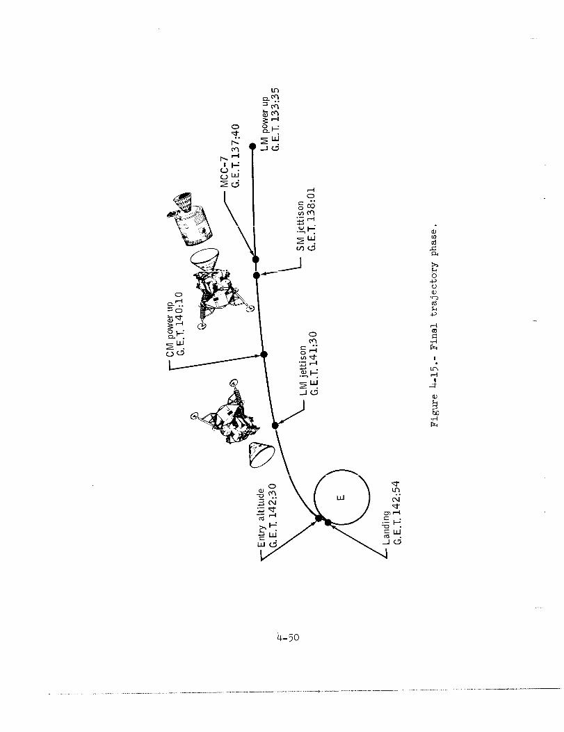
The minimum practical return time was 133 hours g.e.t. to the Atlantic Ocean, and the maximum was 152 hours g.e.t. to the Indian Ocean. Recovery forces were deployed in the Pacific. The return path selected was for splashdown in the Pacific Ocean at lk?:kO g.e.t. This required a minimum of two burns of the LM descent engine. A third burn was subsequently made to correct the normal maneuver execution variations in the first two burns. One small velocity adjustment was also made with reaction control system thrusters. All burns were satisfactory. Figures k-14 and k-15 depict the flight plan followed from the time of the acci- dent to splashdown.
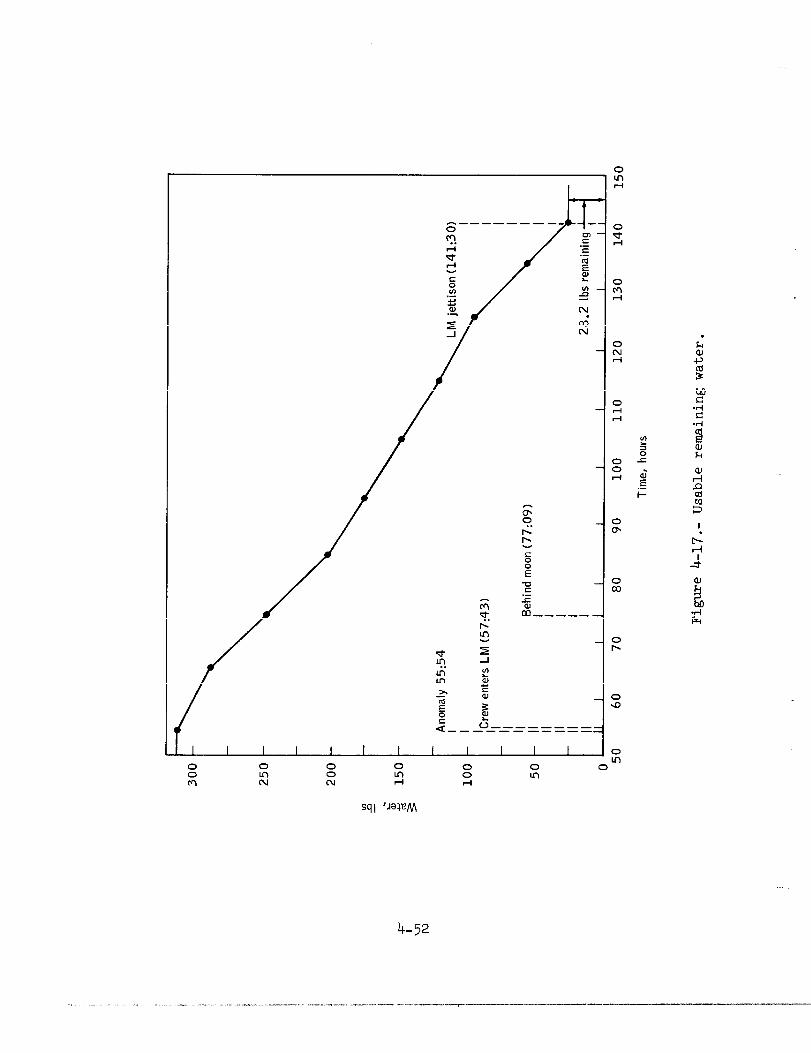
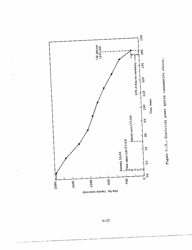
The most critical consumables were water, used to cool the CSM and LM systems during use; CSM and LM battery power, the CSM batteries being for use during reentry and the LM batteries being needed for the rest of the mission; I&l oxygen for breathing; and lithium hydroxide (LiOH) filter cannisters used to remove carbon dioxide from the spacecraft cabin atmosphere. These consumables, and in particular the water and LiOH cannisters, appeared to be extremely marginal in quantity shortly after the accident, but once the LM was powered down to conserve electric power and to generate less heat and thus use less water, the situation improved greatly. Engineers at MSC developed a method which allowed the crew to use materials on board to fashion a device allowing use of the CM LiOH cannisters in the LM cabin atmosphere cleaning system (see fig. 4-16). At splashdown, many hours of each consumable remained available (see figs. k-17 through k-19 and table b-111).
4-48
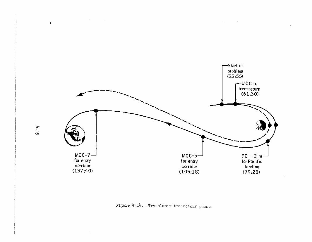
for entry for entry corridor corridor
(137:40> (105:18)
for Pacific landing
(79:28)
Figure b-14.- Translunar trajectory phase.
I 0
4-50
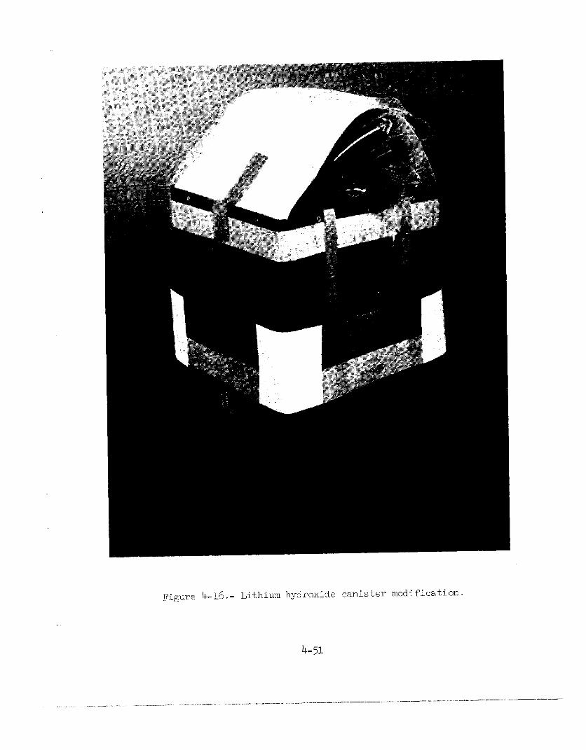
Figure h-16.- Lithium hydroxide canister modification.
4-51
. . I=
4-52
0
I I I I I I I m 0
0 0 0
0 0 0 8 0 0
a N m u 0
N l-l G-l
4-53
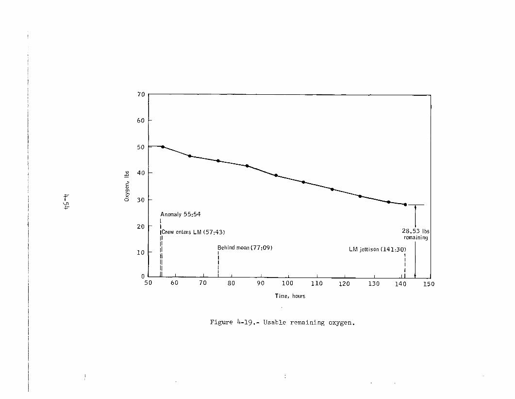
70
Anomaly 55:54 I
20 i
t ICrew enters LM (57:43) 28.23 Ibs II remaining il
10 - II
Behind moon (77:09) I
LM jettison (141:30)
I I I
I I I
0 I I 1 I I I I I II T
50 60 70 80 90 100 110 120 130 140 150
Time, hours
Figure b-19.- Usable remaining oxygen.
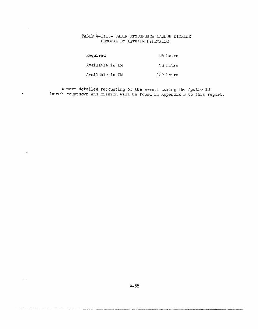
TABLE b-III.- CABIN ATMOSPHERE CARBON DIOXIDE RFSIOVAL BY LITHIUM HYDROXIDE
Required 85 hours
Available in LM 53 hours
Available in CM 182 hours
A more detailed recounting of the events during the Apollo 13 launch countdown and mission will be found in Appendix B to this report.
4-55
. , I _ . . . . - . . - . - . , __“. . _ - - - / , . . . . _ _._ ~ - - . . -_ - - .“.C_-_-r . - . - - _ . - . _ ~.l_l__“-----_.-_
.yll~l_--i-ll

This page left blank intentionally.
4-56
NASA - MSC - Coml.. Houston, Texas
.,.“_.. ,“. .*. _..- __L , --I_. I-..-l-.._--l __l̂ _l__” _-._.- . . . ..- I__- _-.- “_. .I_^ -.-_ _____- ,. _l__. ._.___..-,I. I.._I_-qx ., _.-.-_-- -_l * ., -_