chapter twenty-two: branching by using flow control · the items between the if and the end if...
TRANSCRIPT

Brown & Sharpe
PC-DMIS 3.5 Reference Manual Branching by Using Flow Control •••• 22-1
Chapter Twenty-two: Branching by Using Flow Control
Introduction Suppose you have a part with many features, but you just want to measure a few features over and over to get a comprehensive statistical set of data for those features. Suppose you want to jump to a particular part in your part program dependent on a response from the user. You can accomplish tasks such as these, and many others, by using flow control commands. By setting up conditions for certain commands, you can control the flow of your part program.
This chapter will provide you with the information you need to accomplish such tasks. It explains the syntax conditional statements, loops, and subroutines. It also provides many code samples.
Note: When looping or branching occurs in the code samples, indentation has been used for clarity to show statements assigned to a certain condition. In the actual Edit window code, you won't see any indentation.
The main topics covered in this chapter include the following:
• Using Control Pairs
• Creating Generic Loops
• Ending Generic Loops
• Creating Labels
• Jumping to a Label
• Jumping to a Label Based on Conditions
• Branching on a CMM Error
• Branching with Subroutines
Using Control Pairs The Control Pairs submenu offers various paired commands that work within the Edit window to govern or "control" the proper flow of the part program. To insert a

Brown & Sharpe
22-2 •••• Branching by Using Flow Control PC-DMIS 3.5 Reference Manual
control pair type command into the Edit window, simply type the command, or choose a command from this submenu.
If / End If
The If / End If menu option allows you to add a conditional block to the part program. The items between the IF and the END IF commands will only execute if the expression for the IF command evaluates to true (nonzero). Otherwise, flow of execution will jump to the first command after the END/IF command.
The Edit window command line for a IF / END IF statement reads: IF/expressionEND_IF/
To insert the If / End If commands:
1. Place the cursor in the desired location of the Edit window.
2. Select If / End If from the menu bar. The IF / END IF statement will appear in the Edit window.
Code Sample of If / End If Consider the following example that asks the user if he or she would like measure a point feature.
C1= COMMENT/YESNO,Would you like to measure the point feature,PNT1?IF/C1.INPUT=="YES"PNT1=FEAT/POINT,RECT……ENDMEAS/
END_IF/
Explanation of Sample Code C1=COMMENT/YESNO
This line takes and stores the YES or NO response from the user.
IF/C1.INPUT=="YES"This line is the expression. It tests to see if the input of comment 1 is a YES. If it's a YES then the IF statement is TRUE and continues executing the statements after the IF statement, in this case it measures the PNT1 feature. If NO it moves to the END_IF statement.
END_IF This line ends the execution of commands inside the IF / END IF block of code. Any command following this line is where PC-DMIS will goto if the user clicks No at the comment.
Else If / End Else If The Else If / End Else If menu option allows you to add a conditional block to the part program. The items between the ELSE IF and the END ELSE IF commands will only execute if the expression for the ELSE IF command evaluates to true (nonzero). The ELSE IF / END ELSE IF block must be positioned directly after an IF / END IF block or another ELSE IF / END ELSE IF block. If all IF / ELSE IF expressions above the current block have evaluated to false, then the expression will be evaluated. If the expression evaluates to false (zero), then execution will jump to the

Brown & Sharpe
PC-DMIS 3.5 Reference Manual Branching by Using Flow Control •••• 22-3
next command following the END ELSE IF command. If any of the IF / ELSE if expressions above the current block evaluate to true, all subsequent ELSE IF / END ELSE IF blocks in this sequence will be skipped.
The Edit window command line for a ELSE IF / END ELSE IF statement reads: ELSE_IF/expressionEND_ELSE_IF/
To insert the ELSE IF / END ELSE IF commands:
1. Place the cursor in the desired location of the Edit window, after an existing IF/END IF statement or ELSE IF/END ELSE IF statement.
2. Select Else If / End Else If from the menu bar. The ELSE IF / END ELSE IF statement will appear in the Edit window.
Note: This type of block is only valid when positioned after an IF / END IF or ELSE IF / END ELSE IF block. Invalidly positioned control pairs are shown in red text in the Edit window.
Code Sample of Else If / End Else If Consider the following example that displays a message notifying the user when any one of the X, Y, or Z values for a measured point exceeds defined tolerances:
PNT2=FEAT/POINT,RECT……ENDMEAS/IF/PNT2.X<6.9 OR PNT2.X>7.1COMMENT/OPER,"The measured X value of PNT2: " + PNT2.X+ " is out of tolerance."
END_IF/ELSE_IF/PNT2.Y<3.3 OR PNT2.Y>3.5
COMMENT/OPER,"The measured Y value for PNT2: " +PNT2.Y + " is out of tolerance."
END_ELSEIF/ELSE_IF/PNT2.Z<.9 OR PNT2.Z>1.1
COMMENT/OPER,"The measured Z value for PNT2: "+ PNT2.Z + " is out of tolerance."
END_ELSEIF/
Explanation of Sample Code This code first tests the X value of the point. If the condition evaluates to false, then the code tests for the Y value. If the condition for the Y value evaluates to false, then it tests for the Z value.
If any of these conditions evaluates to true, PC-DMIS displays the comment associated with it and skips the remaining conditional statements.
IF/PNT2.X<6.9 OR PNT2.X>7.1This line is the expression. It tests to see if the measured X value is less than 6.9 or greater than 7.1. If it exceeds either of these boundaries it executes the first comment.
END_IF This line ends the execution of commands inside the IF / END IF block

Brown & Sharpe
22-4 •••• Branching by Using Flow Control PC-DMIS 3.5 Reference Manual
of code. Any command following this line is where PC-DMIS will go to if the IF THEN condition evaluates to false.
ELSE_IF/PNT2.Y<3.3 or PNT 2.Y>3.5This line is the expression for the first ELSE_IF command. It only gets executed if the IF / END IF block above it returns false. It tests to see if the measured Y value is less than 3.3 or greater than 3.5. If it exceeds either of these boundaries it executes the second comment.
END_ELSEIF/This line ends the execution of commands inside the first ELSE IF / END ELSE IF block of code.
ELSE_IF/PNT2.Z<.9 OR PNT2.Z>1.1This line is the expression for the second ELSE IF command. It only gets executed if the ELSE IF / END ELSE IF block above it returns false. It tests to see if the measured Z value is less than .9 or greater than 1.1. If it exceeds either of these boundaries it executes the second comment
END_ELSEIF/This line ends the execution of commands inside the second ELSE IF / END ELSE IF block of code.
Else / End Else The Else / End Else menu option allows you to add a conditional block to the part program. The items between the ELSE and the END ELSE commands will execute only if all other if / end if and else if / end else if blocks above the else block have failed (All evaluated to zero). ELSE / END ELSE blocks must be located at the end of a set of IF / END IF or ELSE IF / END ELSE IF blocks in order to be valid.
The Edit window command line for a ELSE / END ELSE statement reads: ELSE/END_ELSE/
To insert Else / End Else commands:
1. Place the cursor in the desired location of the Edit window. Note that Else / END ELSE blocks must be positioned after a IF / END IF or ELSE IF / END ELSE IF blocks.
2. Select Else / End Else from the menu bar. The ELSE / END ELSE statement will appear in the Edit window.
Code Sample of Else / End Else Consider the following example that asks the user if he or she would like measure a point feature.
C1= COMMENT/YESNO,Would you like to measure the point feature,PNT1? Clicking No measures the next feature.IF/C1.INPUT=="YES"PNT1=FEAT/POINT,RECT……ENDMEAS/
END_IF/ELSEPNT2=FEAT/POINT,RECT…

Brown & Sharpe
PC-DMIS 3.5 Reference Manual Branching by Using Flow Control •••• 22-5
…ENDMEAS/
ENDELSE
Explanation of Sample Code C1=COMMENT/YESNO
This line takes and stores the YES or NO response from the user.
IF/C1.INPUT=="YES"This line is the expression. It tests to see if the input of comment 1 is a YES. If it's a YES then the IF statement is TRUE and continues executing the statements after the IF statement, in this case it measures the PNT1 feature. If NO it moves to the END_IF statement.
END_IF This line ends the execution of commands inside the IF / END IF block of code. Any command following this line is where PC-DMIS will go to if the user clicks No at the comment.
ELSEIf the above IF / END IF block evaluates to false then command lines falling after this line and before the ENDELSE line will be executed. In this case, PNT2 gets executed.
ENDELSEThis line ends the execution of commands inside the ELSE / ENDELSE block of code.
While / End While The While / End While menu option allows you to add a conditional loop to the part program. The items between the WHILE and the END WHILE command will continue to execute in a loop until the condition (or expression) keeping the loop activated is no longer met, meaning the expression for the while loop evaluates to FALSE (i.e. zero). The WHILE command can be added anywhere in the part program. The expression is tested at the start of each loop.
The Edit window command line for a WHILE / END WHILE statement reads: WHILE/expressionEND_WHILE/
To insert a While / End While option:
1. Place the cursor in the desired location of the Edit window.
2. Select While / End While from the menu bar. The WHILE / END WHILE statement will appear in the Edit window.
Code Sample of While / End While Consider the following example that measures a feature an amount specified by the part program user.
C1=COMMENT/INPUT,How many times would you like to measure PNT1?Please type an integer only.ASSIGN/COUNT = 0WHILE/COUNT < C1.INPUT
PNT2=FEAT/POINT,RECT……

Brown & Sharpe
22-6 •••• Branching by Using Flow Control PC-DMIS 3.5 Reference Manual
…ENDMEAS/ASSIGN/COUNT = COUNT + 1COMMENT/OPER,"Measured " + COUNT + " out of " + C1.INPUT +" times."
END_WHILE/
Explanation of Sample Code C1=COMMENT/INPUT
This line takes and stores the integer input from the user into the variable C1.INPUT.
ASSIGN/COUNT = 0This line initializes COUNT, a user-defined variable, and gives it an initial value of 0. The code uses this variable to count the number of times PC-DMIS measures the feature inside the loop.
WHILE/COUNT < C1.INPUTThis line is the expression. It tests to if the value of COUNT (initially set to 0) is less than the integer selected by the user. If this tests true, then the statements in following WHILE/ and before END_WHILE/ are executed
ASSIGN/COUNT = COUNT + 1This line increments the COUNT variable by one so that it eventually exits the loop when it fails the condition test.
COMMENT/OPER,"Measured " + COUNT + " out of " + C1.INPUT+ " times."
This line displays a message showing the number of times, out of the total, that the loop is running.
END_WHILE This line ends the execution of commands inside the WHILE / END WHILE block as long as the condition is false. Other wise when PC-DMIS encounters this command it loops back to the WHILE statement.
Do / Until The Do / Until menu option allows you to add a conditional loop to the part program. The items between the DO and the UNTIL commands will continue to execute in a loop until the expression of the UNTIL command evaluates to TRUE (nonzero). The DO/ UNTIL commands can be added anywhere in the part program. The expression is tested at the end of each loop.
The Edit window command line for a DO / UNTIL statement reads: DO/UNTIL/ expression
To insert DO / UNTIL commands:
1. Place the cursor in the desired location of the Edit window.
2. Select Do / Until from the menu bar. The DO / UNTIL statements will appear in the Edit window.
Code Sample of Do / Until Consider the following example that measures a feature an amount specified by the part program user. This is similar to the example given under the While / End While

Brown & Sharpe
PC-DMIS 3.5 Reference Manual Branching by Using Flow Control •••• 22-7
topic, except that PC-DMIS tests for the condition at the end of the loop instead of at the beginning.
C1= COMMENT/INPUT,Type the number of times PC-DMIS shouldmeasure the PNT1 feature:(type an integer only)ASSIGN/COUNT = 0DO/
PNT1=FEAT/POINT,RECT……ENDMEAS/ASSIGN/COUNT = COUNT + 1COMMENT/OPER,"Measured " + COUNT + " out of " + C1.INPUT +" times."
UNTIL/COUNT == C1.INPUT
Explanation of Sample Code C1=COMMENT/INPUT
This line takes and stores the integer input from the user into the variable C1.INPUT.
ASSIGN/COUNT = 0This line initializes COUNT, a user-defined variable, and gives it an initial value of 0. The code uses this variable to count the number of times PC-DMIS measures the feature inside the loop.
DO/Begins the DO / UNTIL loop. All statements are executed at least once and program flow exits out of the loop once the expression evaluates to false.
ASSIGN/COUNT = COUNT + 1This line increments the COUNT variable by one so that it eventually exits the loop when it fails the condition test.
COMMENT/OPER,"Measured " + COUNT + " out of " + C1.INPUT+ " times."
This line displays a message showing the number of times, out of the total, that the loop is running.
UNTIL/COUNT == C1.INPUT This line ends the execution of commands inside the DO / UNTIL loop as long as the condition evaluates to false. Otherwise, when PC-DMIS encounters this command it loops back to the DO statement.
Select / End Select The Select / End Select menu option allow for the addition of a conditional block that is used in conjunction with the CASE / END CASE and Default Case / End Default Case pairs. The expression for the Select command provides data that is compared against the expression in the Case statements. If the two expressions evaluate to the same thing, then the statements within the Case / End Case Block will execute. The SELECT / END SELECT block surrounds the sets of CASE / END CASE and DEFAULT CASE / END DEFAULT CASE blocks.
The Edit window command line for a SELECT / END SELECT statement reads: SELECT/expressionEND_SELECT/
To insert the Select / End Select commands:

Brown & Sharpe
22-8 •••• Branching by Using Flow Control PC-DMIS 3.5 Reference Manual
1. Place the cursor in the desired location of the Edit window.
2. Select Select / End Select from the menu bar. The SELECT / END SELECT statements will appear in the Edit window.
Code Sample of Select / End Select The pairs, SELECT / END_SELECT, CASE / END_CASE, DEFAULT CASE / END_DEFAULT CASE, all work together evaluate multiple conditions providing a wide range of alternatives.
Suppose you have five circles, labeled CIR1 through CIR5, and you want the operator to be able to measure a circle by simply pressing a key on the keyboard. You could use code similar to the following:
Entire Code DO/C1=COMMENT/INPUT,Type a number to measure that circle:,FOR CIR1 - Type 1,FOR CIR2 - Type 2,FOR CIR3 - Type 3,FOR CIR4 - Type 4,FOR CIR5 - Type 5,Any other character exits the loopSELECT/C1.INPUT
CASE1/CIR1=FEAT/CIRCLE……ENDMEAS/
END_CASECASE2/
CIR2=FEAT/CIRCLE……ENDMEAS/
END_CASECASE3/
CIR3=FEAT/CIRCLE……ENDMEAS/
END_CASECASE4
CIR4=FEAT/CIRCLE……ENDMEAS/
END_CASECASE5
CIR5=FEAT/CIRCLE……ENDMEAS/
END_CASEDEFAULT CASECOMMENT/OPER,Now exiting loop.END_DEFAULT CASE
END_SELECTUNTIL C1.INPUT < 1 OR C1.INPUT > 5
Explanation of Sample Code

Brown & Sharpe
PC-DMIS 3.5 Reference Manual Branching by Using Flow Control •••• 22-9
SELECT/C1.INPUTThis line of code takes a number or string value (in this case a number) typed by the user and determines which CASE/END_CASE block will execute from the input. Notice that SELECT / END_SELECT pair surrounds the entire list of code. All CASE / END_CASE and DEFAULT CASE / END_DEFAULT CASE pairs must reside within these two lines.
END_SELECTThis marks the end of the code held inside the SELECT / END SELECT pair.
CASE1 through CASE5Depending on the value of C1.INPUT, one of the CASE code blocks executes. For example, if C1.INPUT evaluates to 1, the CASE 1 block of code executes, measuring CIR1. If it evaluates to 2, then the CASE 2 block of code executes, measuring CIR2, and so forth.
END_CASE These lines end the specific case blocks of code.
DEFAULT CASEIf the value of the C1.INPUT doesn’t match any of the defined CASE statements (if the value isn’t a number one through five) then the DEFAULT CASE code block executes. In this case it displays a message letting you know that you are exiting the loop.
Notice how the DO / UNTIL loop surrounds the entire code sample. This allows the user to continue to choose from the menu created from the COMMENT/INPUT line until the user selects a character not recognized by the CASE statements.
Case / End Case The Case / End Case menu option allows you to add a conditional block to the part program. The items between the CASE and the END CASE commands will execute if the expression for the case statement evaluates to a value equal to the expression of the corresponding SELECT command. Otherwise, the block of statements will be skipped. The CASE / END CASE statement block must be located directly after a SELECT command or an END CASE command of a previous CASE / END CASE block. Also, PC-DMIS cannot compare multiple expressions on a single case statement.
The Edit window command line for a CASE / END CASE statement reads: CASE/expressionEND_CASE/
To insert the Case / End Case option:
1. Place the cursor in the desired location of the Edit window. Note the positional requirements stated above.
2. Select Case / End Case from the menu bar. The CASE / END CASE statements will appear in the Edit window.
Default Case / End Default Case The Default Case / End Default Case menu option allows you to add a conditional block to the part program. The items between the DEFAULT CASE and the END DEFAULT CASE commands will execute if all other expressions in

Brown & Sharpe
22-10 •••• Branching by Using Flow Control PC-DMIS 3.5 Reference Manual
previous CASE / END CASE blocks within the corresponding SELECT / END SELECT block evaluated to false. Only one DEFAULT CASE / END DEFAULT CASE block is allowed within a SELECT/ END SELECT block. The DEFAULT CASE / END DEFAULT CASE block must be located after all CASE / END CASE blocks within the SELECT / END SELECT block.
The Edit window command line for a DEFAULT CASE / END DEFAULT CASE statement reads: DEFAULT CASE/END_DEFAULT_CASE/
To insert DEFAULT CASE/ END DEFAULT CASE commands:
1. Place the cursor in the desired location of the Edit window noting positional limitations as stated above.
2. Select Default Case / End Default Case from the menu bar. The DEFAULT CASE / END DEFAULT CASE statements will appear in the Edit window.
Creating Generic Loops
Looping Parameters dialog box
The Looping menu option allows you to repeat the part program (or portions of the part program) with or without any of the offsets. The LOOP command can be added anywhere in the part program, although this function is most useful at the beginning and end of the program.
To Use Looping: 1. Select Looping from the menu bar. The Looping Parameters
dialog box will appear.
2. Make any necessary changes to the boxes.
3. Select parameters as needed (i.e. Number of Parts, Start Number, Skip Number, offsets in XY or Z, Angle).
4. Place the cursor in a location in the Edit window where you want to begin the loop.
5. Select the OK button.
The Edit window command line for looping reads: VARNAME = LOOP/START, ID = Y/N, NUMBER = 0, START = 1,

Brown & Sharpe
PC-DMIS 3.5 Reference Manual Branching by Using Flow Control •••• 22-11
SKIP = ,OFFSET: XAXIS = 0, YAXIS = 0, ZAXIS = 0, ANGLE = 0
Note: To complete the looping procedure, you must have an End Loop command inside the Edit window. PC-DMIS will loop Edit window commands that the LOOP/START and LOOP/END commands encompass. See "End Loop" on page 22-12 for more information.
Uses for Looping There are three main uses for the looping option:
1) You have a multiple part fixture that holds a grid of parts. The fixture should use consistent spacing between the rows. The translation / rotation offsets allow you to index from one part to the next in the grid of parts.
2) You have a fixture that holds one part and you want to swap in a new part before each loop of the program. A COMMENT command is helpful to stop the CMM when the part is being replaced with a new one. The command can be at the beginning or end of the loop.
3) You want to use the LOOP option to rotate the part program to measure a different portion of the same part. For example, you could create a part program to measure a complicated hole pattern that was duplicated 10 times on the part. Your part program would only need to measure one of the hole patterns. The LOOP option could be used to offset this part program to measure the other 9 occurrences of the pattern.
Variable ID
The Variable ID box allows you to define the variable name used to track the loop's current iteration (or current loop within the number of specified loops). During the part program's execution, this variable will be equal to the current iteration number of the loop.
XYZ Axis
These boxes sets up the x (y or z) offset between parts, or patterns on the same part. The first offset is based on the part's origin.
Angle

Brown & Sharpe
22-12 •••• Branching by Using Flow Control PC-DMIS 3.5 Reference Manual
The Angle box sets up the angular offset between parts, or patterns on the same part. The first offset is based on the part's origin.
Number of Parts
The Number of Parts box tells PC-DMIS the number of parts that the fixture holds (or patterns on the part) in the x (y or z) direction. PC-DMIS will also ask for the starting part (pattern) number.
Example: You have 10 parts in the x (y or z) direction, and you want to start with position number 5. Enter 10 (ten) for the total number of parts and 5 (five) for the starting position.
Start Number
The Start Number box tells PC-DMIS the starting position number in a series of parts.
Example: You have 10 parts, and you want to start with position number 5, you would enter 10 for the total number of parts and 5 for the starting position.
Skip Number
The Skip Number box repeats a part program the indicated number of times, allowing you to skip a specified increment.
Example: You can set the parameter to skip every third increment of the loop. If the number three is indicated, PC-DMIS will measure the first and second part and then skip to the fourth part.
Loop Ids
If this option is selected, PC-DMIS increments the feature ID's (within the loop) to coincide with the loop increment.
Example: CIR1 will become CIR1[1] on the first loop, CIR1[2] on the second loop, and so on.
End Loop
The End Loop button completes the looping process. The command LOOP/START must be followed by the command LOOP/END in the Edit window.

Brown & Sharpe
PC-DMIS 3.5 Reference Manual Branching by Using Flow Control •••• 22-13
The Edit window command line for ending a loop reads: LOOP/END
Ending Generic Loops The End Loop menu option does the same thing as the End Loop command button in the Loop Parameters dialog box. It inserts a LOOP/END command in the Edit window, thus completing the looping process.
Creating Labels The Label option opens the Edit Label Name dialog box which allows you to create a name identification that can be used with a GOTO or IF statement.
Edit Label Name dialog box
PC-DMIS will allow you to create the ID using up to fifteen characters. The ID will be displayed using all capital letters.
The Edit window command line for the Label option reads: ID = LABEL/
To create a label:
1. Select the location in the Edit window.
2. Select Label from the menu bar.
3. Type the ID for the label in the New Label Name box.
4. Click the OK button.
5. The label ID will appear in the next possible location in the Edit window.

Brown & Sharpe
22-14 •••• Branching by Using Flow Control PC-DMIS 3.5 Reference Manual
Jumping to a Label
GoTo dialog box
The Goto option will bring up the GoTo dialog box which allows you to create GOTO statements within your part program. When the program is executed and PC-DMIS encounters a GOTO statement, it will move to the location of the label identification.
The Edit window command line for GOTO reads: GOTO/label_ID
To create a GOTO Statement in the Edit window:
1. Select Goto from the submenu.
2. Select the label you want to use from the Current Labels box.
3. Click the OK button.
The Goto dialog box also allows you to create new label ID’s that can then be attached to a GOTO statement. To do this:
1. Select Goto from the submenu.
2. Type the name of the label you will create in the Goto Label box. The GOTO/label command is entered in the Edit window.
Note: If a label is created within the GoTo dialog box, you must create the label identification using the Label menu option prior to executing the part program.
Goto Label
The GoTo Label box allows you to type in an existing label that the part program will GOTO.

Brown & Sharpe
PC-DMIS 3.5 Reference Manual Branching by Using Flow Control •••• 22-15
Current Labels
The Current Labels box contains a listing of existing labels which you can select with the mouse.
Jumping to a Label Based on Conditions
If Expression dialog box
The If Goto option will allow you to create IF GOTO statements within your part program. When the part program is executed and PC-DMIS encounters an IF statement, it will GOTO the location of the label identification if the specified expression evaluates to a non-zero value. See the "Using Expressions and Variables" chapter for information on creating expressions.
The Edit window command line for an IF_GOTO statement reads: IF_GOTO/expression, GOTO=Label
Expression
The Expression button brings up the expression builder. With the expression builder you can create a variety of different expressions that you may need within your part program. See the "Using Expressions and Variables" chapter for information on using expressions.
Label
The Label box allows you to type in the Label that PC-DMIS will use for the GOTO command. The Label button brings up the Goto dialog box. From this dialog box
Brown & Sharpe
22-16 •••• Branching by Using Flow Control PC-DMIS 3.5 Reference Manual
you can choose the label to be used. The label will appear in the Label box. See "Jumping to a Label" on page 22-14.
Branching on a CMM Error
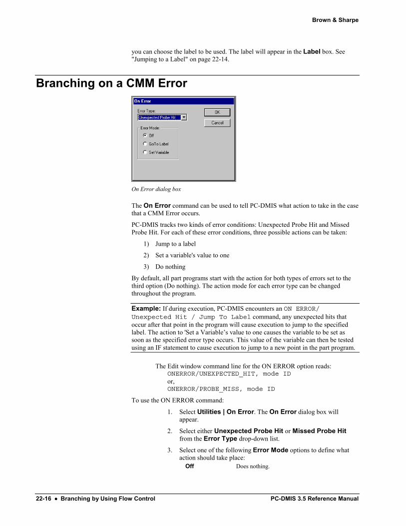
On Error dialog box
The On Error command can be used to tell PC-DMIS what action to take in the case that a CMM Error occurs.
PC-DMIS tracks two kinds of error conditions: Unexpected Probe Hit and Missed Probe Hit. For each of these error conditions, three possible actions can be taken:
1) Jump to a label
2) Set a variable's value to one
3) Do nothing
By default, all part programs start with the action for both types of errors set to the third option (Do nothing). The action mode for each error type can be changed throughout the program.
Example: If during execution, PC-DMIS encounters an ON ERROR/Unexpected Hit / Jump To Label command, any unexpected hits that occur after that point in the program will cause execution to jump to the specified label. The action to 'Set a Variable’s value to one causes the variable to be set as soon as the specified error type occurs. This value of the variable can then be tested using an IF statement to cause execution to jump to a new point in the part program.
The Edit window command line for the ON ERROR option reads: ONERROR/UNEXPECTED_HIT, mode IDor, ONERROR/PROBE_MISS, mode ID
To use the ON ERROR command:
1. Select Utilities | On Error. The On Error dialog box will appear.
2. Select either Unexpected Probe Hit or Missed Probe Hit from the Error Type drop-down list.
3. Select one of the following Error Mode options to define what action should take place:
Off Does nothing.

Brown & Sharpe
PC-DMIS 3.5 Reference Manual Branching by Using Flow Control •••• 22-17
Goto Label Jumps to a defined label. Set Variable Sets a variable's value to one.
4. Click the OK button to apply the ON ERROR option. The Cancel button will close the On Error dialog box without applying any changes.
Error Type The Error Type drop-down window allows you to choose one of these Error Types:
• Unexpected Probe Hit
• Missed Probe Hit
Off When the CMM has an error, choosing the Off option commands PC-DMIS to do nothing.
Goto Label When the CMM has an error, choosing the Goto Label option commands the part program to jump to a defined label
Set Variable When the CMM has an error, choosing the Set Variable option commands the part program to set a variable's value to one.
Supported Interfaces Not all interfaces support the ON ERROR command. Consult the following table to see if your interface is supported.
• If your interface is listed, a small block box indicates what error type is supported by that interface.
• If your interface isn't listed, then it's not able to use the ON ERROR command.
Supported Interfaces
Unexpected Probe Hit
Missed Probe Hit
B&S Standard ■ ■ Dea ■
Elm ■ ■ Federal/Renault ■ ■
Johansson ■ ■
Leitz ■ ■
LK Direct (aka LKRS232)
■ ■
LK Driver ■ ■
Metrolog ■ ■
Mititoyo Bright ■ ■
Mitutoyo ■ ■

Brown & Sharpe
22-18 •••• Branching by Using Flow Control PC-DMIS 3.5 Reference Manual
Mora ■ ■
Omnitech ■ ■
Renishaw ■ ■ Sharpe ■ ■
Sheffield ■ ■
Wenzel ■ ■
Zeiss ■ ■
Branching with Subroutines The Subroutine option allows you to access part program commands from the current file (or external file) and use these commands repeatedly. PC-DMIS will allow you to pass arguments to and from the subroutine. The only limitation to the number of arguments and nested subroutines is the amount of available memory. The external subroutine does not have access to features, variables or alignments from the main part program. It simply allows you to pass the necessary data. However, the subroutine does have access to items within the part program.
The Edit window command line for a sample subroutine would read: SUBROUTINE/name,S1 = Arg1 : Description
name = the name of the subroutine. S1 = the local variable name to be used in the subroutine. This variable generally cannot be accessed outside of the subroutine. Arg1 = the default value for the first argument. Description = The description of the argument in the subroutine.
ENDSUB/ is used to end the subroutine definition.
The types of arguments that can be passed into a subroutine are numeric values, variables, text strings and feature names.
Passing Numeric Characters into a Subroutine To pass numeric characters, simply type the number in the Value box of the Argument Edit dialog box. See "Creating a New Subroutine" on page 22-19 for more details.
Passing Variables into a Subroutine Arguments that can pass data back are variables. Enter the variable in the Value box of the Argument Edit dialog box. See "Creating a New Subroutine" on page 22-19 for more details.
When you use a variable as an argument to a subroutine, any changes that occur to the corresponding variable in the subroutine are passed back and become the value of the variable that was passed in.
Example: This example shows how a variable, used as an argument to a subroutine, value is passed back from a subroutine: The variable V1 is assigned the value 6: ASSIGN/ V1 = 6. A subroutine call passes V1 as the first argument: CALL/SUB; MySub, V1. The subroutine is defined as follows. SUBROUTINE/MySub,A1 = 0. A1 is the name for the first argument so when the call is made, A1 will have the same value that V1 did at the time of the call, 6. The

Brown & Sharpe
PC-DMIS 3.5 Reference Manual Branching by Using Flow Control •••• 22-19
subroutine contains one statement: ASSIGN/ A1 = A1 + 1. This increments the value of A1 to 7. The subroutine ends, END /SUBROUTINE. Flow of execution returns to the statement directly following the call sub command. As execution jumps back, any variables that were used as arguments, V1 in this case, are updated to the value of the corresponding variables in the subroutine, A1 in this case. So V1 now has a value of 7. The value was passed back from the subroutine.
Passing Text Strings into a Subroutine To pass a text string, place the alphanumeric within the Value box of the Argument Edit dialog box. See "Creating a New Subroutine" on page 22-19 for more details. Make sure the alphanumeric characters are placed within double quotations, for example; "Pass this text1."
Passing Feature Names into a Subroutine Feature names are passed within curly brackets, for example; {F1} would be placed within the Value box of the Argument Edit dialog box to call the feature designated as F1 into the Edit window.
Also, when passing the feature name, the subroutine has full access to that feature. The subroutine can change any theoretical value of the feature. For example: if feature F1 is passed in, to set the theo X values, use the command ASSIGN/F1.TX= 5 in the Edit window.
Creating a New Subroutine To create a new subroutine:
1. Select Subroutine from the submenu. This brings up the Subroutine Creation dialog box. For information on this dialog box, see the "Understanding the Subroutine Creation Dialog Box" topic on page 22-20.
Subroutine Creation dialog box
2. Type the name for the subroutine in the Name box.
3. Click the Add Arg button. The Argument Edit dialog box appears. For information on this dialog box, see the "Understanding the Argument Edit Dialog Box" topic on page 22-22.

Brown & Sharpe
22-20 •••• Branching by Using Flow Control PC-DMIS 3.5 Reference Manual
Argument Edit dialog box
4. Type the name for the argument in the Name box.
5. Click in the Value box
6. Type the value for the argument in the Value box.
7. Click in the Description box.
8. Type a description of the argument in the Description box. This description will appear next to the argument in the Edit window.
The Cancel button will cancel any changes you made to an argument and return you to the Subroutine Creation dialog box.
Note: You can also delete arguments by using the Delete Arg button in the Subroutine Creation dialog box.
Understanding the Subroutine Creation Dialog Box The following topics describe the various options available in the Subroutine Creation dialog box.
Subroutine Creation dialog box
Subroutine Name
Brown & Sharpe
PC-DMIS 3.5 Reference Manual Branching by Using Flow Control •••• 22-21
In the Name box, type in the name of the subroutine you are creating.
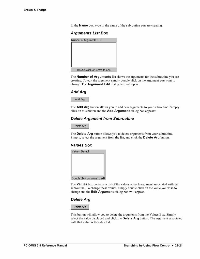
Arguments List Box
The Number of Arguments list shows the arguments for the subroutine you are creating. To edit the argument simply double click on the argument you want to change. The Argument Edit dialog box will open.
Add Arg
The Add Arg button allows you to add new arguments to your subroutine. Simply click on this button and the Add Argument dialog box appears:
Delete Argument from Subroutine
The Delete Arg button allows you to delete arguments from your subroutine. Simply, select the argument from the list, and click the Delete Arg button.
Values Box
The Values box contains a list of the values of each argument associated with the subroutine. To change these values, simply double click on the value you wish to change and the Edit Argument dialog box will appear.
Delete Arg
This button will allow you to delete the arguments from the Values Box. Simply select the value displayed and click the Delete Arg button. The argument associated with that value is then deleted.

Brown & Sharpe
22-22 •••• Branching by Using Flow Control PC-DMIS 3.5 Reference Manual
Editing an Existing Subroutine To edit an existing subroutine:
1. Place your cursor on the subroutine in the Edit window.
2. Press F9. This brings up the Subroutine Creation dialog box. For information on this dialog box, see the "Understanding the Subroutine Creation Dialog Box" topic on page 22-20.
3. Select the argument you wish to change in the Number of Arguments box. The Argument Edit dialog box opens. For information on this dialog box, see the "Understanding the Argument Edit Dialog Box" topic on page 22-22.
4. Make the necessary changes in the desired boxes.
5. Click the OK button to close the Argument Edit dialog box and save your changes. Here you can choose other arguments to edit.
When you're finished editing your subroutine, click the OK button to save your changes and return to PC-DMIS main window.
The Cancel button will cancel any changes you made to an argument and return you to the Subroutine Creation dialog box.
Note: You can also delete arguments by using the Delete Arg button in the Subroutine Creation dialog box
Understanding the Argument Edit Dialog Box The following topics describe the various options available in the Argument Edit dialog box.
Argument Edit dialog box
Argument Name
In the Name box you enter the name for the argument you are creating or editing.
Argument Value
In the Value box you enter the value of the argument. Valid values are:
• Numeric

Brown & Sharpe
PC-DMIS 3.5 Reference Manual Branching by Using Flow Control •••• 22-23
• Variable
• Text String
Argument Description
In the Description box you can enter a description of the argument. This description will appear next to the argument in the Edit window.
Ending a Subroutine The End Sub menu option ends a subroutine by placing an "ENDSUB/" command in the Edit window.
To place this command:
1. Place your cursor in the desired spot of the Edit window.
2. From the submenu, select End Sub.
The "ENDSUB/" command will appear in the Edit window.
Calling a Subroutine
Call Subroutine dialog box
The Callsub menu command will call an already existing subroutine from the current part program into a different location, or from a different part program into the current part program.
To call a subroutine:
1. Select the Call Sub option from the submenu. The Call Subroutine dialog box opens.
2. Click the Select Subroutine button. The Select Subroutine dialog box opens.

Brown & Sharpe
22-24 •••• Branching by Using Flow Control PC-DMIS 3.5 Reference Manual
Select Subroutine dialog box
3. Select either the User Directory check box or the Current Directory check box or both. If the part program the subroutine is from resides in the directory specified to be searched for subroutines, select the User Directory check box. If it is from the current directory, mark the Current Directory check box. PC-DMIS lists all the part programs available for selection.
4. Select the part program which contains the subroutine you want. You will see all subroutines associated with the selected program appear in the Subroutine Name box.
5. Select the subroutine you want to call.
6. Click the OK button. The subroutine information you are going to call will appear in the Call Subroutine dialog box.
7. Click the OK button again and the called subroutine will appear in the selected location of the Edit window.
The Edit window command line for a sample called subroutine reads:
CS2 =CALLSUB/name, file\prog:Arg1,…
CS2 = the label created for the Call Sub command. name = the option name of the subroutine to be called. file = the part program that contains the subroutine. (If this field is blank, PC-DMIS will look in the calling part program for the subroutine). prog = the name of the part program from which the subroutine is called Arg1 = the argument to be passed to the subroutine. (If this field is blank, the default value will be used.).
Note: In your CALLSUB command you should keep a set of pointers to all of the objects made for the subroutine so that you can easily refer to them afterwards using the subroutine's ID. For more information on pointers, see "Pointers" in the "Using Expressions and Variables" chapter.
The Call Subroutine dialog box also allows you to add, edit, or delete arguments to the called subroutine.

Brown & Sharpe
PC-DMIS 3.5 Reference Manual Branching by Using Flow Control •••• 22-25
To add a new argument using the Call Subroutine Dialog box:
1. Click the Add Arg button. The Argument Edit dialog box will appear.
2. Click in the Value box.
3. Type the value for the argument in the Value box.
4. Click in the Description box.
5. Type a description of the argument in the Description box. This description will appear next to the argument in the Edit window.
To edit existing arguments using the Call Subroutine Dialog box:
1. Double click on the value of the argument you want to change. A value box will appear which shows the default value for the called subroutine.
2. Type a new value.
3. Click the OK button.
See "Creating a New Subroutine" on page 22-19 and "Editing an Existing Subroutine" on page 22-22 for additional information on how to edit or create new arguments for a subroutine.
To delete arguments from a CALLSUB command: 1. Place the cursor on the CALLSUB command.
2. Press F9 to access the Call Subroutine dialog box.
3. Select the desired argument(s) from the list.
4. Click the Delete Arg button.
5. Click OK.
You can also delete an argument in the Edit window text directly. To do this,
1. Place PC-DMIS in Command mode.
2. Place the cursor on the CALLSUB command, and press TAB until you highlight the desired argument.
3. Type the letters "del". This will delete the argument. Pressing DELETE or BACKSPACE won't work. They merely change the argument to an empty argument.
Using CALLSUB Statements in Master / Slave Mode If you mark a CALLSUB statement as Master Only; all of the commands in
the subroutine will be marked as Master Only when the subroutine is called.
If you mark a CALLSUB statement as Slave Only; all of the commands in the subroutine will be marked as Slave Only when the subroutine is called.
If you mark a CALLSUB statement for both arms, PC-DMIS leaves the subroutine markings as they were originally setup.

Brown & Sharpe
22-26 •••• Branching by Using Flow Control PC-DMIS 3.5 Reference Manual
If a subroutine contains a MOVE/SYNC command in it, and you mark the CALLSUB statement as Master Only or Slave only, at execution time PC-DMIS displays an error indicating that this is invalid and the subroutine is not called.
For information on assigning a command to execute for a specific arm, see the "Assigning a Command to an Arm" topic in the "Using Master / Slave Mode" chapter.
Understanding the Call Subroutine Dialog Box The following topics describe the various options available in the Call Subroutine dialog box.
Name Box in Call Subroutine
The Name box contains the name of the subroutine you have selected after using the Select Subroutine button.
File Box in Call Subroutine
The File box contains the directory pathway to the subroutine file you have called.
Select Subroutine
The Select Subroutine button brings up the Select Subroutine dialog box.
Select Subroutine dialog box
The Select Subroutine dialog box allows you to call previously created subroutines by searching in the user directory or the current directory.
Code Sample of a Subroutine The following code sample allows the operator to have a choice of changing the theoretical X, Y, and Z values of a feature after its measurement. Subsequent runs will then use the updated theoretical values.

Brown & Sharpe
PC-DMIS 3.5 Reference Manual Branching by Using Flow Control •••• 22-27
PNT1=FEAT/POINT,RECT……ENDMEAS/C1=COMMENT/YESNO,Do you want to change the theoreticalvalues for PNT1?IF/C1.INPUT=="YES"
CS1=CALLSUB/CHANGETHEO,:,END_IF/COMMENT/OPER,The XYZ theoretical and actual values forPNT1 are:,"Theo X= " + PNT1.TX,"Theo Y= " + PNT1.TY,"Theo Z= " + PNT1.TZ,- - - - - - - - - - -,"Actl X= " + PNT1.X,"Actl Y= " + PNT1.Y,"Actl Z= " + PNT1.ZPROGRAM/ENDSUBROUTINE/CHANGETHEO,
POINT1 = {PNT1} : ,=DIMINFO/;DIMID,FEATID;HEADINGS,GRAPHAXIS;MEAS,NOM,TOL,DEV,MAXMIN,OUTTOL, , ,C2=COMMENT/INPUT,Type the new X theo value for PNT 1.,"It's current value is: " + PNT1.TXASSIGN/PNT1.TX = C2.INPUTC3=COMMENT/INPUT,Type the new Y theo value for PNT 1.,"It's current value is: " + PNT1.TYASSIGN/PNT1.TY = C3.INPUTC4=COMMENT/INPUT,Type the new Z theo value for PNT 1.,"It's current value is: " + PNT1.TZASSIGN/PNT1.TZ = C4.INPUT
ENDSUB/
Explanation of Sample Code C1=COMMENT/YESNO
This line takes and stores the YES or NO response from the user.
IF/C1.INPUT=="YES"This line is the expression. It tests to see if the input of comment 1 is a YES. If it's a YES then the IF statement is TRUE and continues executing the statements after the IF statement, in this case it measures the PNT1 feature. If NO it moves to the END_IF statement.
CS1=CALLSUB/CHANGETHEO,:,This line calls the subroutine named CHANGETHEO. The flow of the part program now jumps to the SUBROUTINE/CHANGETHEO line.
SUBROUTINE/CHANGETHEOThis line initializes the CHANGETHEO subroutine. Program flow continues with the execution of code between this line and the ENDSUB/ line.
POINT1 = {PNT1} : , This is the only argument of the subroutine. It allows the subroutine to access information from the PNT1 feature.
Brown & Sharpe
22-28 •••• Branching by Using Flow Control PC-DMIS 3.5 Reference Manual
C2=COMMENT/INPUT, C3=COMMENT/INPUT,C4=COMMENT/INPUT These input comments all take the new theoretical X, Y, and Z values from the user and store them in C2.INPUT, C3.INPUT, and C4.INPUT respectively.
ASSIGN/PNT1.TX = C2.INPUTThis line takes the theoretical X value from C2.INPUT and assigns it to the PNT1.TX variable. PNT1.TX is a PC-DMIS variable that holds the theoretical X value (denoted by TX) for the point with the ID label of PNT1.
ASSIGN/PNT1.TY = C3.INPUTThis line takes the theoretical Y value from C3.INPUT and assigns it to the PNT1.TY variable. PNT1.TY is a PC-DMIS variable that holds the theoretical Y value (denoted by TY) for the point with the ID label of PNT1.
ASSIGN/PNT1.TZ = C4.INPUTThis line takes the theoretical Z value from C4.INPUT and assigns it to the PNT1.TZ variable. PNT1.TZ is a PC-DMIS variable that holds the theoretical Z value (denoted by TZ) for the point with the ID label of PNT1.
ENDSUB/ This line ends the subroutine, and program flow returns to the line immediately following the subroutine call. In this case the END_IF/ statement.
The program flow then continues with the next operator comment which displays the theoretical and actual X, Y, and Z values, and then the part program ends with the PROGRAM/END command.