chapter one magnetism introduction - mwalimundolo.or.ke form 2 notes.pdf · district mocks,kcse...
TRANSCRIPT

District mocks,kcse past papers,notes,form 1- 4 papers available on www.kusoma.co.ke
CHAPTER ONE
MAGNETISM Introduction Magnets are substances that are able to attract and hold items. Lodestone is the only known
natural magnet which was discovered by the Chinese 2,000 years ago. Other magnets produced artificially by man are called artificial magnets.
Magnets and non-magnetic materials Magnetic materials are those that are strongly attracted by magnets while non-magnetic
ones are those that are not affected by magnets. Iron, steel, cobalt and nickel are magnetic substances, while wood, glass and copper are examples of non-magnetic substances.
Substances that are repelled by magnets are said to be diamagnetic whereas those which are strongly attracted i.e. iron, nickel, cobalt are called ferromagnetic materials. The materials
that are so lightly attracted such that the magnet seems to have no effect on them are called
paramagnetic materials (mostly non-magnetic materials). Ferrites are a mixture of iron oxide and barium oxide are the most newly developed magnetic materials. Ceramic magnets or
magnadur magnets are made from ferrites and are very strong.
Properties of magnets 1. They are double poled substances with both the North and South poles.
2. Like poles repel and unlike poles attract. Repulsion is a sure method of determining whether two substances are magnets.
3. The greatest magnetic force is concentrated around the poles of a magnet.
Magnetic field patterns. Magnetic field is the space around a magnet where magnetic field (force) is observed. Plotting field patterns
A line of force gives the direction of the magnetic field at each point along it. Their closeness is a measure of the strength of the magnetic field or of the force that would be exerted by the bar magnet.
Examples of field patterns.

District mocks,kcse past papers,notes,form 1- 4 papers available on www.kusoma.co.ke
The points marked ‘X’ are called neutral points where there is no magnetic field at such points. Watches (non-digital), electron beams in cathode ray tubes and TV sets are shielded from
external magnetic fields by placing a soft-iron cylinder around the neck of the tube or watch.
Making magnets The following are methods used to make magnets.
a) Magnetic induction – this is a process by which magnets are made by placing
ferromagnetic materials in a magnetic field. Materials like iron lose their magnetism easily and are said to be soft while others like steel gain magnetism slowly but retain it
longer and are therefore said to be hard and are used to make permanent magnets.

District mocks,kcse past papers,notes,form 1- 4 papers available on www.kusoma.co.ke
b) Magnetizing by stroking – the object to be magnetized is placed on a bench then a bar
magnet is dragged along the length of the bar from one end to the other. This is repeated several times and the object becomes magnetized. This method is known as
single-stroke method.
c) Magnetizing using an electric current – this is the use of magnetic effect of an electric
current through a solenoid (insulated wire of many turns).
Demagnetizing Demagnetizing is the process of removing magnetic properties of a magnet . The following methods are which a magnet can lose its magnetism;
a) Hammering them hard with their poles facing E-W direction b) Heating them strongly c) Placing a magnet inside a solenoid and passing an a.c. current through it for a short
time.

District mocks,kcse past papers,notes,form 1- 4 papers available on www.kusoma.co.ke
Caring for magnets a) Magnets should be stored in pairs with unlike poles adjacent to each other attached to
pieces of soft iron called keepers.
b) Magnets should not be hammered especially with their poles facing E-W direction.
c) Magnets should not be heated strongly or dropped roughly on hard surfaces. d) Magnets should not be placed near alternating currents.
e) Magnets should be kept dry and clean since rust can make them lose their magnetism.
Uses of magnets 1. Used in making other magnets 2. Used in making loud speakers
3. Used in making moving coil meters 4. Used in making telephone speakers.

District mocks,kcse past papers,notes,form 1- 4 papers available on www.kusoma.co.ke
Domain theory of magnetism. In ferromagnetic substances small atomic magnets form large groups called domains. These atomic magnets face one direction where the direction varies from one domain to another. In
an un-magnetized crystal the directions of these domains are different hence their resultant magnetism is zero.
When a magnetic material is placed in a magnetic field the atomic magnets rotate and eventually all domains face the same direction. When this happens then the material becomes magnetized. When a material is magnetized we say it is saturated. This means that the magnetism of the material cannot be increased by any other method and this is the domain theory of magnetism.
CHAPTER TWO
MEASUREMENT II Measuring length using vernier callipers. Vernier callipers is used when higher accuracy in measurement is required and this cannot be
done using a metre rule.
Vernier callipers has two scales; main scale and vernier scale. Outside jaws are used to measure both lengths and external diameters, inside jaws for measuring internal diameters
while the tail is used for measuring depths of cavities. The main scale is divided into cm and mm. The vernier scale is divided into 10 equal divisions of 0.9 mm each. The accuracy of vernier
callipers is 0.10 mm.

District mocks,kcse past papers,notes,form 1- 4 papers available on www.kusoma.co.ke
The reading is taken in two steps;
a) The main scale is read at zero mark of the vernier scale. The values given in cm. b) The vernier is read at the position where a mark on the vernier scale is exactly lined up
with a mark on the main scale. The values are given as a two decimal of a cm. Examples
1. Give the reading in the following diagram.
Solution Main scale reading: - 2.7 cm Vernier scale reading: - 0.04 cm Adding both we get 2.74 cm.
2. What is the reading of the vernier callipers shown below?
Solution
Main scale reading - 7.6 cm Vernier scale reading - 0.04 cm
Adding both readings we get 7.64 cm.
Micrometer screw gauge It is a device used to measure small lengths. It has an accuracy of 0.01 mm. It has two scales; the sleeve scale and thimble scale. The sleeve scale is divided into upper and lower scales with

District mocks,kcse past papers,notes,form 1- 4 papers available on www.kusoma.co.ke
the upper division in mm and lower divisions in 0.5 mm. Thimble scale is divided into 50 equal
divisions each division consisting of 0.01 mm.
The reading is taken in two steps;
a) The reading on the sleeve scale is read ta the point where it touches the edge of the thimble in mm and half mm.
b) The thimble scale is read at the point where the centre line of the sleeve is parallel to the thimble scale division.
Examples 1. Give the reading in the following.
Solution Sleeve reading – 3.5 mm Thimble reading – 0.45 mm Adding up we get 3.95 mm.

District mocks,kcse past papers,notes,form 1- 4 papers available on www.kusoma.co.ke
2. What is the reading in the following micrometer screw gauge?
Solution Sleeve scale reading – 4.0 mm Thimble scale reading - 0. 32 mm
Adding up the two we get 4.32 mm.
Calculating the size of a molecule. Both the volume and area of a drop can be calculated using the following formulas Volume = 4/3 πr3 and Area = πr2h. Examples 1. A drop of olive oil, whose volume is 0.12 mm3, was placed on a surface of clean water.
The oil spread and formed a patch of area 6.0 × 104 mm2. Estimate the size of the olive
oil. Solution
Volume = 0.12 mm3. Area of the oil patch = 6.0 × 104 mm2. Volume = area × thickness of the patch, therefore Thickness of the oil patch = volume / area = 0.12 / 6.0 × 104 = 2.0 × 10⁻⁶ mm or 2.0 × 10⁻⁹ m.
2. Suppose an oil drop has a volume of 0.10 mm3 and forms a film with a radius of 10 cm. Calculate, the thickness of the oil film. Solution
Area of the film = πr2 = 3.14 × 10 × 10 = 314 cm2 = 31,400 mm2. Thickness of the oil film = volume / area, hence 0.10 / 31,400 = 3.0 × 10⁻⁶ mm. (The thickness of the oil film is called upper limit to the size of molecule because the molecule cannot be bigger than the thickness of the oil film)

District mocks,kcse past papers,notes,form 1- 4 papers available on www.kusoma.co.ke
CHAPTER THREE
TURNING EFFECT OF A FORCE Turning effects The turning effect of a body is called the moment of that force. The turning effect produced depends on both the size of the force and the distance from the pivot. The moment of a force about a point is the product of the force applied and the perpendicular distance from the pivot (or turning point) to the line of action of the force. Hence, Moments of a force = Force × perpendicular distance from pivot.
The law of moments The law of moments states that “when a body is in balance or in equilibrium, the sum of the clockwise moments equals the sum of anti-clockwise moments”. The SI units of the moments of a force is Newton metre (Nm). Examples
1. A uniform rod of negligible mass balances when a weight of 3 N is at A, weight of 3 N is at B and a weight of W is at C. What is the value of weight W?
Solution Taking moments about the fulcrum, O then
Anti-clockwise moments = (3 × 1) + (3 × 3) = 3 + 9 = 12 Nm
Anti-clockwise moments = clockwise moments 3 W = 12 Nm
W = 4 N 2. The following bar is of negligible weight. Determine the value of ‘x’ if the bar is balanced.
10

District mocks,kcse past papers,notes,form 1- 4 papers available on www.kusoma.co.ke
Solution
The distance from the turning point to the line of action can be determined as, 60 cm 1500
d Clockwise moments = 10 × 30 = 300 N cm, Anticlockwise moments = 10 × ‘x’ = 10 x. N cm. Using the principle of moments Anti-clockwise moments = clockwise moments 10 x = 300, hence x = 30 cm.
3. Study the diagram below and determine the value of X and hence the length of the bar.
Solution
Clockwise moments = 15x N + 5(X × 20) N Anticlockwise moments = (20 × 10) + (60 × 10) N cm, = 800 N cm.
Anti-clockwise moments = clockwise moments 800 N cm = 15X + 5X + 100
800 n cm = 20X + 100 20X = 700
X = 35 cm. Therefore, the length of the bar = 40 + 20 + 35 + 20 = 115 cm.
The lever A lever is any device which can turn about a pivot or fulcrum. The applied force is called the effort and is used to overcome the resisting force called the load. We use the law of moments in the operation of levers.

District mocks,kcse past papers,notes,form 1- 4 papers available on www.kusoma.co.ke
Example Consider the following diagram. (The bar is of negligible mass). Determine the effort applied.
Solution
Taking moments about O. Then, clockwise moments = effort × 200 cm. Anticlockwise moments = 200 × 30 cm.
Effort = (200 × 30)/ 200 = 30 N.
CHAPTER FOUR
EQUILIBRIUM AND CENTRE OF GRAVITY. Centre of gravity Centre of gravity or C.G is the point of balance of a body in which the total weight of the body seems to act through. For regular shaped bodies the C.G is at the geometric centre of the body.
For irregular bodies their weight still acts at the centre of the gravity and the law of moments can be used to determine the weight of the body.
Example The figure below shows a uniform bar of weight ‘W’ and length 80 cm. If a force of 20 N keeps it in balance, determine the weight ‘W’ of the bar.
District mocks,kcse past papers,notes,form 1- 4 papers available on www.kusoma.co.ke
Solution Taking moments about the pivot, clockwise moments = W × 20 N cm. Anticlockwise moments = 20 × 30 N cm. Clockwise moments = anticlockwise moments 20 W = 600, therefore W = 30 N.
Parallel forces and equilibrium For a body to be in equilibrium (neither moving nor rotating), under the action of parallel forces, the following conditions will be satisfied;
a) The sum of upward forces must be equal to the sum of downward forces. b) The sum of clockwise moments equals the sum of anticlockwise moments.
The two are called the first and second condition of equilibrium respectively. Examples
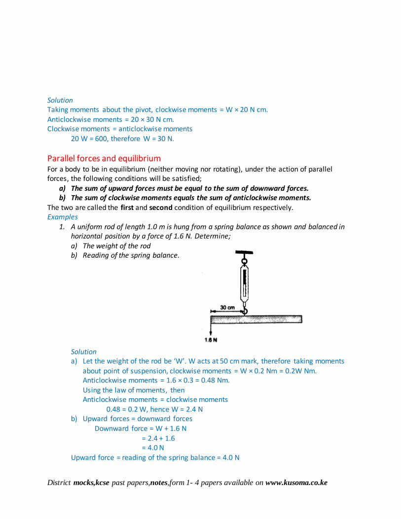
1. A uniform rod of length 1.0 m is hung from a spring balance as shown and balanced in horizontal position by a force of 1.6 N. Determine; a) The weight of the rod b) Reading of the spring balance.
Solution a) Let the weight of the rod be ‘W’. W acts at 50 cm mark, therefore taking moments
about point of suspension, clockwise moments = W × 0.2 Nm = 0.2W Nm. Anticlockwise moments = 1.6 × 0.3 = 0.48 Nm.
Using the law of moments, then Anticlockwise moments = clockwise moments
0.48 = 0.2 W, hence W = 2.4 N b) Upward forces = downward forces
Downward force = W + 1.6 N
= 2.4 + 1.6 = 4.0 N
Upward force = reading of the spring balance = 4.0 N

District mocks,kcse past papers,notes,form 1- 4 papers available on www.kusoma.co.ke
2. A uniform rod is 1.0 m long weighs 5 N. It is supported horizontally at one end by a
spring and the other end rests on a table as shown below. A mass of 2kg is hung from the rod as shown; determine,
a) Reading of the spring balance b) Reaction force, F, from the table.
Solution a) The 2kg mass and the weight of the rod (5 N) gives clockwise moment while the
spring balance provides anticlockwise moments.
Clockwise moments = (2 × 10) × 0.4 + (5 × 0.5) = 10.5 Nm. Anticlockwise moments = S × 1 (reading of the spring balance)
1S = 10.5, hence S = 10.5 N. b) Upward forces = downward forces
Downward forces = (2 × 10) + 5 = 25 N Therefore F+ 10.5 = 25, hence F = 14.5 N.
Stability This is a term which explains how easy or difficult it is for an object to topple over when a force is applied to it. Factors affecting stability, a) Base area – the bigger the base area the more the stability. b) Position of the centre of gravity – the higher the centre of gravity the less stable the body
will be.
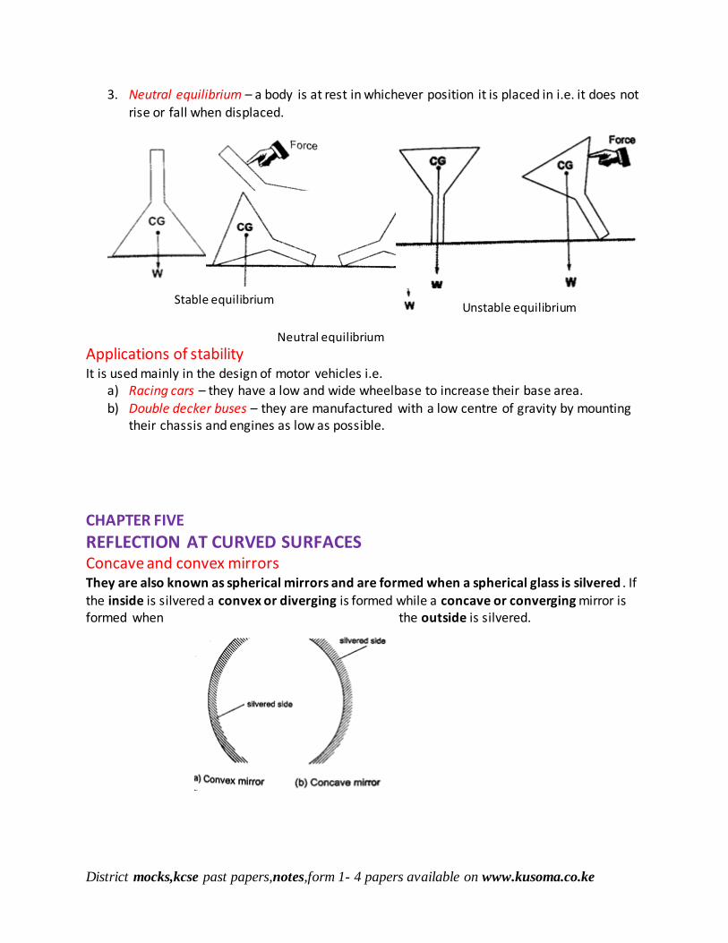
States of equilibrium 1. Stable equilibrium – if a body is displaced by a small amount of force it returns to its
original position. 2. Unstable equilibrium – if a body is displaced by a small amount of force it toppled over
and does not return to its original position.
District mocks,kcse past papers,notes,form 1- 4 papers available on www.kusoma.co.ke
3. Neutral equilibrium – a body is at rest in whichever position it is placed in i.e. it does not
rise or fall when displaced.
Applications of stability It is used mainly in the design of motor vehicles i.e.
a) Racing cars – they have a low and wide wheelbase to increase their base area. b) Double decker buses – they are manufactured with a low centre of gravity by mounting
their chassis and engines as low as possible.
CHAPTER FIVE
REFLECTION AT CURVED SURFACES Concave and convex mirrors They are also known as spherical mirrors and are formed when a spherical glass is silvered . If the inside is silvered a convex or diverging is formed while a concave or converging mirror is formed when the outside is silvered.
Stable equilibrium
Neutral equilibrium
Unstable equilibrium
District mocks,kcse past papers,notes,form 1- 4 papers available on www.kusoma.co.ke
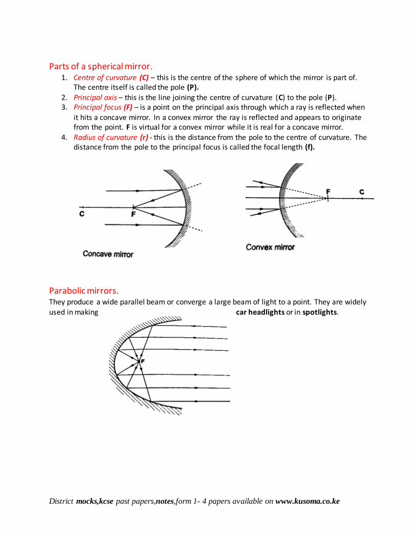
Parts of a spherical mirror.
1. Centre of curvature (C) – this is the centre of the sphere of which the mirror is part of. The centre itself is called the pole (P).
2. Principal axis – this is the line joining the centre of curvature (C) to the pole (P). 3. Principal focus (F) – is a point on the principal axis through which a ray is reflected when
it hits a concave mirror. In a convex mirror the ray is reflected and appears to originate from the point. F is virtual for a convex mirror while it is real for a concave mirror.
4. Radius of curvature (r) - this is the distance from the pole to the centre of curvature. The distance from the pole to the principal focus is called the focal length (f).
Parabolic mirrors. They produce a wide parallel beam or converge a large beam of light to a point. They are widely
used in making car headlights or in spotlights.
District mocks,kcse past papers,notes,form 1- 4 papers available on www.kusoma.co.ke
Images formed by spherical mirrors. Location of images using ray diagrams.
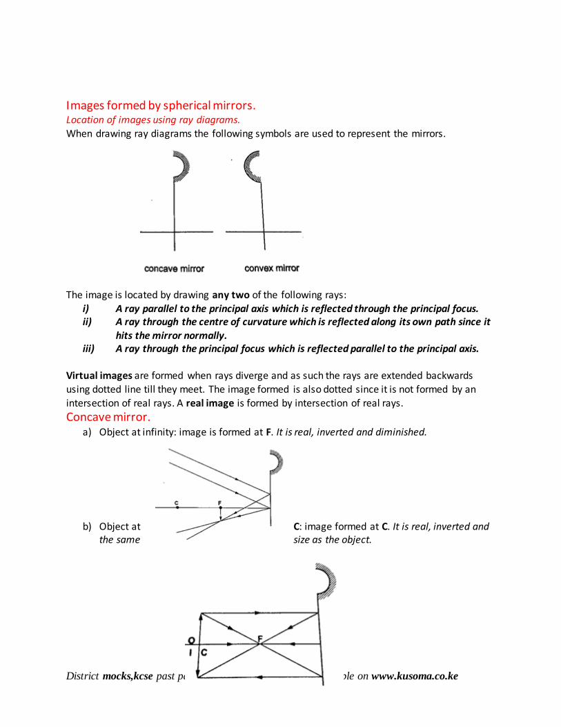
When drawing ray diagrams the following symbols are used to represent the mirrors.
The image is located by drawing any two of the following rays:
i) A ray parallel to the principal axis which is reflected through the principal focus. ii) A ray through the centre of curvature which is reflected along its own path since it
hits the mirror normally. iii) A ray through the principal focus which is reflected parallel to the principal axis.
Virtual images are formed when rays diverge and as such the rays are extended backwards using dotted line till they meet. The image formed is also dotted since it is not formed by an
intersection of real rays. A real image is formed by intersection of real rays.
Concave mirror. a) Object at infinity: image is formed at F. It is real, inverted and diminished.
b) Object at C: image formed at C. It is real, inverted and the same size as the object.

District mocks,kcse past papers,notes,form 1- 4 papers available on www.kusoma.co.ke
c) Object behind C: image is formed between C and F. It is real, inverted and diminished.
d) Object between F and C: Image is formed behind C. It is real, inverted and magnified.
e) Object at F: Image formed is at infinity.
f) Object between F and P: Image is formed behind the mirror. It is virtual, erect and
magnified.
District mocks,kcse past papers,notes,form 1- 4 papers available on www.kusoma.co.ke
Convex mirror.
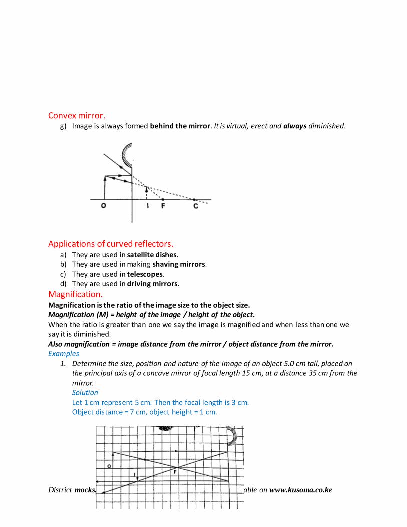
g) Image is always formed behind the mirror. It is virtual, erect and always diminished.
Applications of curved reflectors. a) They are used in satellite dishes. b) They are used in making shaving mirrors.
c) They are used in telescopes. d) They are used in driving mirrors.
Magnification. Magnification is the ratio of the image size to the object size. Magnification (M) = height of the image / height of the object.
When the ratio is greater than one we say the image is magnified and when less than one we say it is diminished.
Also magnification = image distance from the mirror / object distance from the mirror. Examples
1. Determine the size, position and nature of the image of an object 5.0 cm tall, placed on the principal axis of a concave mirror of focal length 15 cm, at a distance 35 cm from the mirror. Solution Let 1 cm represent 5 cm. Then the focal length is 3 cm. Object distance = 7 cm, object height = 1 cm.

District mocks,kcse past papers,notes,form 1- 4 papers available on www.kusoma.co.ke
From the scale drawing, Image position = 5.4 cm × 5 = 27 cm in front of the mirror. Image size = 0.75 cm × 5 = 3.75 cm. Image is real and inverted.
2. A vertical object 5 cm high is placed 10 cm in front of a convex mirror of focal length 15 cm. find the position, size and nature of image formed. Determine the magnification of the image. Solution Let 1 cm represent 5 cm, then the focal length = 3 cm, object size = 1 cm
Object distance = 2 cm.
From the scale drawing,
Image position = 1.2 cm × 5 = 6.0 cm behind the mirror. Image size = 0.6 cm × 5 = 3.0 cm.
The image is virtual and erect. Magnification = image dist. / object dist. Hence 6 /10 = 0.6 (diminished).
CHAPTER SIX
MAGNETIC EFFECT OF AN ELECTRIC CURRENT. Introduction: Oersted’s discovery.

District mocks,kcse past papers,notes,form 1- 4 papers available on www.kusoma.co.ke
Hans Christian Oersted discovered the magnetic effect of a current in 1819. The direction of
the field is dependent on the direction of the current. This discovery brought about the development of electric bells, electric motors, telephone receivers and radios.
Determining the direction of the lines of force. The direction of the lines of force can be determined using a simple rule called the right-hand
screw rule. This rule states that “if a right-hand screw advances in the direction of the current, then the rotation of the screw is in the direction of the field”.
Another rule is the right-hand grip rule which states that “if the wire carrying a current is gripped with the right hand, using the thumb along the conductor and pointing in the
direction of the current, then the direction of curled fingers is in the direction of the lines of force”.

District mocks,kcse past papers,notes,form 1- 4 papers available on www.kusoma.co.ke
Magnetic field due to a solenoid. The rule for polarity. A solenoid is a cylindrical coil of wire acting as a magnet when carrying electric current.
The direction of the field can be determined using a simple rule stated as follows “if the coil (solenoid) is viewed from one end and the current flows in an anticlockwise direction at that end, then that end is the North Pole. If the current flows in a clockwise direction, then that end is the South Pole”.
Electromagnets. An electromagnet is a soft metal core made into a magnet by passing an electric current
through a coil surrounding it. They only maintain their magnetism if current continues to flow, if switched off they lose their magnetism.
Factors affecting the strength of an electromagnet.
1. Increasing current through the coil. 2. Increasing the number of turns of the coil.
3. Using iron of C- core shape which brings both magnetic poles together.

District mocks,kcse past papers,notes,form 1- 4 papers available on www.kusoma.co.ke
Some applications of electromagnets. a) Electric bell When the switch is closed the current passing through the solenoids magnetizes them and
they pull the soft iron armature which makes the hammer hit the gong therefore producing sound. When the hammer hits the gong the contact between the spring and the screw is
broken and then stops the current from flowing. The soft iron core loses its magnetism and releases the armature which is then pulled back by the screw. The contact between the spring and the screw is regained and the process repeats itself again and again therefore
the gong is struck continuously.
‘ b) Telephone receiver. It consists of a u-magnet made by attaching two soft-iron bars to the end of a short
permanent magnet. The solenoids are wound in opposite directions around the bars. When the phone is lifted the current flows through the solenoids depending on the microphone
on the other end of the line. These varying current spasms induce magnetism of varying strengths in the iron bars which in turn causes the magnetic alloy diaphragm to vibrate
differently producing sound.

District mocks,kcse past papers,notes,form 1- 4 papers available on www.kusoma.co.ke
Force on a current-carrying conductor in a magnetic field. When a conductor carries a current in a magnetic field a force acts on it. The direction of the
force depends on the directions of the field and current. The factors affecting the magnitude of the force are;
a) The current flowing in the conductor b) The strength of the magnet c) The length of the conductor in the magnetic field.
The relationship between the directions of the current, field and force are mutually perpendicular. They are summarized in a law called Fleming’s right-hand rule or the motor rule. This rule states that “if you hold the first finger, the second finger and the thumb of your left hand mutually perpendicular to each other, so that the first finger points in the direction of the magnetic field and the second finger points in the direction of the current in the
conductor, then the thumb points in the direction of the force acting on the conductor”.
Applications of the force on a conductor. Simple D.C motor. Consists of a rectangular coil of wire mounted on an axle which can rotate between the poles of
a magnet. For the rotation to be continuous the ends of the coil is connected to half-rings called the split-ring commutators. The battery terminals are attached to brushes which slide on these
half-rings. D.C motors are useful as car starter motors, hand drills, machine motors, fans etc.

District mocks,kcse past papers,notes,form 1- 4 papers available on www.kusoma.co.ke
CHAPTER SEVEN
HOOKE’S LAW. Hooke’s law states that “the extension of a spring is proportional to the applied force, provided that the force is not large enough to deform the spring permanently”.
Mathematically expressed as Force α extension.
Spring constant Since Force α extension then Force / Extension = constant (k). The constant of proportionality (k) is called the spring constant. F / e = k or Force (N) = k e. The spring constant is a measure of the stiffness of a spring. The greater the constant the stiffer the spring.
The spring constant varies with the following;- a) Material – identical springs mad of different materials will have different constants i.e.
steel and copper. b) Diameter – the stiffness decreases with the increase in diameter.
c) Thickness of the wire – a spring made of a thicker wire is stiffer than the one made of thin wire of the same material.
d) Length of spring – a short spring is stiffer than a longer one. e) Number of turns per unit length – a spring with higher number of turns per unit length is
less stiff than the one with fewer turns per unit length.
Example 1. If the springs shown below are similar and the constant of proportionality (k) is
100 Nm-1, determine total extension in each arrangement.

District mocks,kcse past papers,notes,form 1- 4 papers available on www.kusoma.co.ke
Solution a) k = 100 100 Nm-1, extension = force / k = 10 / 100 = 0.1 m = 10 cm. b) Extension of the lower spring = 10 cm, extension of the two parallel springs = 5 cm.
Total extension = 10 + 5 = 15 cm. c) Extension of the two lower springs = 5 cm Middle spring extend by = 10 cm Upper two springs extend by = 5 cm
Total extension = 5 + 10 + 5 = 20 cm.
The spring balance It is made up of a spring mounted in a metal or plastic casing. The spring is fitted with a pointer which moves along a calibrated scale divided into ten equal parts.

District mocks,kcse past papers,notes,form 1- 4 papers available on www.kusoma.co.ke
Examples
1. A load of 4 N causes a certain copper wire to extend by 1.0 mm. Find the load that will cause a 3.2 mm extension on the same wire. (Assume Hooke’s law is obeyed). Solution
F α e also F1 / F2 = e1 / e2 = F2 = (4 × 3.2) / 1.0 = 12.8 N.
2. A body of 200 g was hung from the lower end of a spring which obeys Hooke’s law.
Given that the spring extended by 100 mm, what is the spring constant for this spring? Solution F = α e, F = k e. F = 200 × 10-3 kg × 10 N /kg = 2 N. Extension = 100 × 10-3 m = 0.1 m. Spring constant (k) = 2 / 0.1 = 20 N/m.
3. Two identical springs, whose spring constant is 6.0 N/cm, are used to support a load of 60 N as shown below. Determine the extension of each spring.
Solution
Since the springs are parallel their spring constant equals 2k. Therefore extension = Force / k = 2 F / k = 60 / 2 × 6 = 5 cm.
Each spring will extend by 5 cm.
CHAPTER EIGHT
WAVES I A wave is simply a disturbance that moves through a medium. Other waves do not require a medium to travel i.e. they can travel in a vacuum, are known as electromagnetic waves e.g.

District mocks,kcse past papers,notes,form 1- 4 papers available on www.kusoma.co.ke
radio, X-rays, gamma rays UV rays etc. Other waves require a material medium to be
transferred and are called mechanical waves i.e. water, sound waves etc.
Transverse and longitudinal pulses and waves. 1. Transverse waves – they consist of a crest and a trough. In this case the displacement of
the medium caused by these pulses are perpendicular to the direction in which the wave (disturbance) travels. A pulse is a single non-repeated disturbance. If the pulses are repeated periodically (regularly) they produce a series of waves called periodic
transverse wave train. They can be produced as shown below. Examples are water waves, light and radio waves.
2. Longitudinal waves – these are waves whereby the particles of the medium vibrate
parallel to the direction of movement of the disturbance. When several turns of a spring are pulled together (compression) and then released they tend to spread out to their original position. When pulled apart (rarefaction) they also turn to their original position. In this case the displacement of the spring is parallel to the motion of the wave and this is known as longitudinal. Examples are the sound waves.
Characteristics of waves 1. All waves have speed which depends on the nature of disturbance. 2. All waves have wavelength (distance between two successive points in a wave).
Represented by the symbol λ and is measured in metres.

District mocks,kcse past papers,notes,form 1- 4 papers available on www.kusoma.co.ke
3. All waves have frequency ‘f’ which is the number of waves passing a point in one
second. It is measured in cycles per second or hertz (Hz). The period of a wave is the time required for a complete wave to pass a given point.
Therefore T = 1 / f or f = 1 / T (period is measured in seconds). The speed ‘v’ is given as; v = λ / T, since f = 1 / T then
v = (1 / T) × λ = f λ or v = f λ. This is the wave equation. 4. All waves have amplitude which is the maximum displacement of the particles of the
medium as the wave passes. Examples
1. A rope is displaced at a frequency of 3 Hz. If the distance between two successive crests of the wave train is 0.8 m, calculate the speed of the waves along the rope. Solution v = f λ = 3 × 0.8 = 2.4 m Hz = 2.4 m/s.
2. The figure below illustrates part of the displacement-time graph of a wave travelling across water at a particular place with a velocity of 2 ms-1. Calculate the wave’s;
a) Amplitude b) Frequency (f) c) Wavelength (λ)
Solution a) From the graph, maximum displacement (a) = 0.4 cm
b) From the graph, period T = time for one cycle = 0.20 seconds So f = 1 / T = 1 / 0.20 = 5 Hz.
c) Velocity = f λ hence λ = 2 / 5 = 0.4 m.
CHAPTER NINE

District mocks,kcse past papers,notes,form 1- 4 papers available on www.kusoma.co.ke
SOUND. Sound is an important example of a longitudinal wave which is composed of both compressions and rarefactions. The frequency range in which compressional disturbances occur is called the
sonic spectrum and is very large. Sound is a range of compressional wave frequencies sensitive to human ear and is known as audio range which ranges from 20 Hz to 20,000 Hz.
Compressional waves with frequencies above and below the audio range are called ultrasonic and infrasonic frequencies respectively.
Nature and transmission of sound waves. Sound waves require a material medium for transmission from one point to another. Sound
waves therefore cannot be transmitted in a vacuum. The rate of transmission diminishes as you move from solids, to liquids then to gases.
Characteristics of sound waves 1. Intensity and loudness – intensity of sound refers to the rate of flow of energy through
an area. The loudness of a sound generally varies with the intensity of sound. The frequency of sound waves determines their intensity while the amplitude determines
their loudness. 2. Frequency and pitch – pitch refers to the sharpness of a sound and is determined by its
frequency. 3. Fundamental tones and harmonics – fundamental frequency is the vibration in a wire
which has the lowest possible frequency. The fundamental frequency and the tones with the frequencies that are whole multiples of the fundamental are called
harmonics. The fundamental frequency is also the first harmonic. The number of segments vibrating in a string depends on the point at which the string is plucked.
4. Quality

District mocks,kcse past papers,notes,form 1- 4 papers available on www.kusoma.co.ke
of sound or timbre – quality of sound can be improved by adding the second harmonic
to the fundamental frequency hence the quality depends on the number of harmonics produced simultaneously and their relative intensities.
Echo Echoes are produced by reflection of sound waves from hard surfaces such as a wall or a cliff. To hear an echo, the sound waves travels double the distance between the source and the reflector. So to determine the velocity of sound ‘v’ between two successive claps is given as v = distance from the reflecting surface / half the time taken between two successive claps Hence; speed ‘v’= distance / time = m/s. Example A boy strikes a railway line (steel) with a hammer. If the speed of sound in steel is 5,200 m/s, determine the time taken for the sound to reach another boy 2.3 km down the railway line with
his ear on the rail. Solution
Time taken = distance / speed = 2300 / 5200 = 0.44 seconds.
Factors affecting the speed of sound
a) Temperature – speed increases with increase in temperature especially gases since the change in liquids and solids is small it can be neglected.
b) Nature of transmitting medium – different substances transmit sound waves at various speeds as shown below (i) Air – 346 m/s (ii) Hydrogen – 1339 m/s (iii) Water – 1498 m/s (iv) Aluminium – 5,000 m/s
(v) Iron – 5,200 m/s (vi) Glass – 4,540 m/s
Example A girl claps her hands once at a distance 250 m from a vertical cliff. If the temperature in the
surrounding is 50C, how long does it take for her to hear the echo? Solution Distance travelled = 250 × 2 = 500 m

District mocks,kcse past papers,notes,form 1- 4 papers available on www.kusoma.co.ke
Speed of sound = (331.5 m/s at 00) the speed in air increases at about 0.6 m/s per 0C.
Therefore speed at 50C = 331.5 + (0.6 × 5) = 334.5 m/s Time taken = distance / speed = 500 / 334.5 = 1.5 seconds.
CHAPTER TEN
FLUID FLOW
Fluid in physics refers to liquids and gases. To study fluid flow we have to make the following assumptions:
1. We consider fluids to be incompressible 2. We assume that they have little or no internal friction or viscosity.
Streamline and turbulent flow. The path followed by a small element of a moving fluid is called a line of flow . A streamline is
a curve whose tangent at any point is in the direction of the fluid velocity at that point. A streamline flow occurs when all elements of a fluid passing a particular point follow the same
path or line of flow as the elements that passed through that point previously. A streamline flow is achieved only when the speed is low. If the speed increases it is characterized by whirls
and eddies then it becomes a turbulent flow. Turbulent flow generally occurs when the speed is high and where there are sharp bends along the path of the fluid.
Equation of continuity Consider a fluid flowing (streamline flow) through a horizontal pipe with different cross-
sectional areas as
shown.

District mocks,kcse past papers,notes,form 1- 4 papers available on www.kusoma.co.ke
Let the cross-sectional area in both sections be A1 and A2 and the corresponding speeds of the fluid be V1 and V2 respectively. The volume of fluid flowing per second in each section is given by; V = A L = A v t = A v. Where L, v t and v is the distance moved in one second. Since the volumes in each section is the same, then A1 V1 = A2 V2, hence A v = constant.
The above equation is known as the equation of continuity. Since A1 > A2, then V2 > V1. i.e. the speed increases when a tube narrows. The quantity (A v) is called volume efflux i.e. volume flowing per second. Example. A horizontal pipe of cross-sectional area 50 cm2 carries water at the rate of 0.20 litres per second. Determine the speed;
a) Of the speed of water in the pipe. b) When the tube narrows to 20 cm2 at another point.
Solution a) Volume efflux = o.20 l per second = A v
From V (volume) = A v, then v = V / A = 0.20 × 10⁻³ / 50 × 10-4 = 0.04 m/s b) Since A1 v1 = A2 v2 then v2 = (0.05 × 0.04) / 0.02 = 0.1 m/s
Bernoulli’s principle Daniel Bernoulli (1700 – 1782) explained the variation of pressure exerted by a moving fluid when its speed is changed. The pressure is lower where the speed is higher.

District mocks,kcse past papers,notes,form 1- 4 papers available on www.kusoma.co.ke
Bernoulli’s principle states that “For a fluid flowing through a tube, the sum of the pressure,
the kinetic energy per unit volume and the potential energy per unit volume of the fluid is a constant”. Mathematically expressed as;
P + ½ ρ v2 + ρ g h = constant. Where P – pressure, ρ – density, v= velocity, g – acceleration due to gravity and h – height.
Bernoulli’s effect When air is blown through the tunnel formed, the area marked ‘T’ collapses inwards showing
that pressure outside is more than the one inside the tunnel. The pressure inside the tunnel decreases as the air through it increases in speed.
Applications of Bernoulli’s principle. 1. Car carburetor – inside the carburetor the air passage is partially constricted at the point
where petrol mixes with air hence air intake increases the speed of air while decreasing the pressure inside for petrol to vaporize quickly before it gets to the cylinder where combustion occurs.

District mocks,kcse past papers,notes,form 1- 4 papers available on www.kusoma.co.ke
2. Horizontal pipe – for a streamline flow through a pipe the term ρ g h is eliminated from the Bernoulli’s equation leaving P + ½ ρ v2 = constant, indicating that pressure in liquid is greatest when speed is least. When this is combined with the equation of continuity, the pressure is then greatest when the pipe is widest hence the following observation.
3. Dynamic lift - when air is blown at the top a flat sheet of paper the ends of the paper moves upward and this because the speed of air on top of the paper is greater than
below and according to Bernoulli’s principle the pressure on top lowers and the pressure below becomes sufficient enough to produce a force which moves the paper
upwards. This is what is referred to as the dynamic lift since it is caused by motion. The upward force is equal to the product of the pressure difference and the area of the
surface lifted. It is applied in the taking off of airplanes, the trajectory of a spinning ball, paint sprayer and Bunsen burner among others.

District mocks,kcse past papers,notes,form 1- 4 papers available on www.kusoma.co.ke