chapter iii microcontroller based system design...
TRANSCRIPT

Electronic System Design for Tensometer
Microcontroller based system design approach - 65 -
Chapter III
Microcontroller Based System Design Approach
3.1 Introduction:
The tensometer or UTM have an arrangement for applying tensity to an object
under test, and monitor its compression/expansion as well as in some cases the break
point of the object material. For the objects composed of metals, concrete and other
hard materials the compression/expansion is very small, limited to tens of microns to
few millimeters. This test gives the idea about the object’s strengths as well as
deformation under the stress conditions. Such tests are very useful and necessary in
the industries like construction, fabrication, metal forging, and molding.
A tensometer is a device used to evaluate the Young's modulus (how much it
stretches under strain) of a material and other tensile properties of materials, such as
tensile strength. The material under test is usually loaded with a sample between the
two grips that are either adjusted manually or automatically to apply force to the
specimen. The machine works either by driving a screw or by hydraulic ram. The
hydraulic ram is much flexible when applying force and can create various loading
patterns such as the cyclical loads needed for measurement of fatigue strength.
Like tensometer, the Universal Testing Machine (UTM) is useful for testing
the tensile and compressive properties of materials. It supports tensile, compression,
bending and many more tests. Such machines are equipped with Load cells and
extensometers, to measure the key parameters of force and deformation of the sample
being tested. These machines are widely used in materials testing laboratories.
UTM characteristics:
• UTM consist of hydraulic loading unit and hydraulic control console.
• UTM’s are equipped with auto load selector, graphic recording attachment and
large dial type load indicator.
• UTM’s are highly reliable and easy to operate.

Electronic System Design for Tensometer
Microcontroller based system design approach - 66 -
A typical testing system is comprised of a Universal Testing Machine and its
control, accessories, parts and devices used to hold and support the test specimen. A
tension test may be a destructive test in the sense that the specimen will be finally
broken or fractured into two pieces. To perform the tensile test, the universal testing
machine should be capable of applying sufficient load which will break or fracture the
material. The test piece or specimen of the material is generally a straight piece,
uniform in the cross-section over the test length and often with enlarged ends for
holding in the machine holders. Two fine marks are often made near the end of
uniform test section of the specimen and the distance between these points is termed
as "gauge length". The gauge length is that length which is under study or observation
when the experiment on the specimen is performed. The specimen is placed in the
machine between the holders and any measuring device, such as extensometer to
record the change in length is fitted on to the specimen between the gauge points.
3.2 Mechanical arrangement for displacement measurement -
Traditional setup for displacement measurement in Tensometer and universal
testing machine arms is composed of a strip chart recorder or a telescopic
arrangement, which provide limited precision. This arrangement suffers from the
drawback of mechanical as well as human reading errors. Apart from the friction of
mechanical parts, mechanical errors are also inserted by the basic principle of
operation of the measurement system; for strip chart recorder the manual positioning
of the pen on the chart, Pen fitting, and vibrations present in the system induce error.
Similarly in case of telescopic arrangement the positioning of telescope, parallax,
screw backlash contribute to the error.
The electronic motion control system proposed is intended to minimize or
eliminate some of these errors by employing electronic means for optical tracking of
the tensometer arm. The system sits side by side with the tensometer and keeps
tracking its motion. Unlike the strip-chart recorder this system setup does not apply
any loading to the tensometer, thus eliminating the loading effects of the measurement
apparatus.

Electronic System Design for Tensometer
Microcontroller based system design approach - 67 -
3.3 Electronic system setup
Fig 3.1. Electronic motion control system setup
Fig 3.2. Electronic motion control system arrangement
The system block diagram is shown in fig 3.1. and the system arrangement is
shown in fig. 3.2. The system is composed of a linear motion controller mechanical
setup and an electronic circuitry to control motion of the linear motion controller so as
to track the tensometer arm. The mechanical setup includes a carriage hosted on a
platform and driven by a rotating screw. The screw is coupled to stepper motor which
rotates clockwise or anticlockwise to move the carriage in forward or reverse
direction. The precision of the motion control system depends on the screw type and
construction, motor stepping angle, and screw-motor coupling.
Fig 3.3. Electronic circuit setup for linear motion controller
Mechanical arrangement
Electronic logic circuits
sensors
actuators
Single Board Computer
Stepper motor driver
Regulated power supply
LCD Module
Keypad Interface
Sensor Interface

Electronic System Design for Tensometer
Microcontroller based system design approach - 68 -
The electronic circuitry designed around the 89S52, the MCS-51 family
microcontroller is shown in fig 3.3. The microcontroller-stepper motor interface
includes an optocoupler (MCT2E) which isolates them physically. The
microcontroller read the position of the carriage with the help of IR receiver-
transmitter pair, moving it from the origin towards the current position of the
tensometer arm. It then counts the number of steps required for the travel and
calculate the displacement. The system drives the stepper motor using half stepping
drive mode to improve the precision.
3.4 Design of Single Board Computer using AT89S52: [1-9]
Microcontrollers are better suited as CPU for the SBC’s used in embedded
systems. The best example is the SBC designed around ATMEL’s AT89S52. This
microcontroller is in-system programmable via its on-chip SPI port. ISP facility is one
of the most desired facility during the design phases of embedded systems. ISP
capable microcontrollers minimize the hardware and speed up the design process.
Fig 3.4: Single Board Computer block diagram
The SBC board block diagram is shown in the fig 3.4 and the schematic of the
same is shown in the fig 3.5
MCS51Microcontroller
RS232 Serial transceiver
I2C serial RTC
I2C serial EEPROM

Electronic System Design for Tensometer
Microcontroller based system design approach - 69 -
Fig 3.5(a): Single Board Computer schematic
Fig. 3.5b: ISP interface
Fig. 3.5c: RS232 serial interface

Electronic System Design for Tensometer
Microcontroller based system design approach - 70 -
Fig. 3.5d: I2C serial EEPROM
Fig. 3.5e: I2C serial real time clock

Electronic System Design for Tensometer
Microcontroller based system design approach - 71 -
3.4.1 Functional description:
The block diagram shows the major building blocks of the single board
computer; viz. CPU with on-chip ports, reset circuit, crystal oscillator, in-system
programming interface, serial I2C EEPROM, real time clock and RS232 serial
interface. All these devices make it a standalone single board computer(SBC) ideal
for data logger applications.
The SBC supports two CPUs; Philips P89C51RD2 and ATMEL AT89S52.
Table 3.1 highlights the main features of these microcontrollers. Both the devices
have a good number of I/O ports to which variety of analog and digital I/O devices
can be interfaced, e.g. ADC, DAC, LCD module, LED displays, DTMF
decoders/encoders, etc. Two port lines are dedicated for use with I2C compatible
devices such as EEPROM, RTC, ADC, etc. The SBC has been already equipped with
EEPROM and RTC, which are desired components for data logger applications. The
RTC provides the precision time base for the system. RTC used in the system is
Philips PCF8583, which is a clock/calendar with 240 × 8-bit RAM. Its main features
are listed below.
3.4.2 RTC features: +
• Operating supply voltage: 2.5 V to 6 V
• Clock operating supply voltage (0 to +70 °C): 1.0 V to 6.0 V
• 240 × 8-bit low-voltage RAM
• Data retention voltage: 1.0 V to 6 V
• Operating current (at fSCL = 0 Hz): max. 50 µA
• Clock function with four year calendar
• Universal timer with alarm and overflow indication
• 24 or 12 hour format
• 32.768 kHz or 50 Hz time base
• Programmable alarm, timer and interrupt function

Electronic System Design for Tensometer
Microcontroller based system design approach - 72 -
The RTC features show that the RTC can also be used for storage purpose,
when the system requires small storage memory. The other uses could be timer
interrupt for refreshing I/O devices, e.g. LCD data refreshing.
The SBC supports ATMEL AT24Cxx I2C serial EEPROM family. This family
has EEPROM with density of 1Kb to 1Mb, which provides flexible solutions for
designers, they can add as much memory as the application demands. Main features
of this family are listed below.
3.4.3 EEPROM features: +
• Low-Voltage and Standard-Voltage Operation – 1.8V to 5.5V
• Low-Power Devices (I =2 µA at 5.5V)
• Internally Organized 4096 x 8, 8192 x 8
• Schmitt Tr igger, Filtered Inputs for Noise Suppression
• Bidirectional Data Transfer Protocol
• 100 kHz (1.8V, 2.5V, 2.7V) and 400 kHz (5V) Clock Rate
• Write Protect Pin for Hardware Data Protection
• 32-Byte Page Write Mode (Partial Page Writes Allowed)
• Self-Timed Write Cycle (10 ms max)
• High Reliability
– Endurance: 1 Million Write Cycles
– Data Retention: 100 Years
• 8-Pin JEDEC PDIP, 8-Pin JEDEC SOIC, 8-Pin EIAJ SOIC,
and 8-pin TSSOP Packages
The SBC can be connected to the communicating devices via RS232 serial
terminal. The microcontroller has on-chip UART with RS232 protocol support, which
is useful for communicating over a serial line. The UART generates RS232 frames at
various baud rates, under control of microcontroller. It is therefore relieves the
microcontroller from manipulating RS232 data streams. With AT89S52 clocked at
11.0592 MHz the board supports maximum 57600 baud rate, while the 89C51RD2
clocked at the same frequency and 6 clock cycles per machine cycle configuration

Electronic System Design for Tensometer
Microcontroller based system design approach - 73 -
will support double baud rates that that of the 89S52. The crystal frequency of
11.0592 MHz provides all the standard baud rates with maximum accuracy.
Table 3.1: Supported microcontrollers and their features
Philips P89C51RD2 AT89S52
• Compatible with MCS-51 Products
• On-chip Flash Program Memory with
In-System Programming (ISP) and In-
Application Programming (IAP)
capability
• Can be programmed by the end-user
application (IAP)
• 6/12 clocks per machine cycle
operation
• Speed up to 20 MHz with 6 clock
cycles per machine cycle (40 MHz
equivalent performance); up to 33 MHz
with 12 clocks per machine cycle
• Fully static operation
• 4 level priority interrupt
• 8 interrupt sources
• Full-duplex enhanced UART
• Power control modes
– Clock can be stopped and resumed
– Idle mode
– Power down mode
• Programmable clock out
• Second DPTR register
• Compatible with MCS-51 Products
• 8K Bytes of In-System Programmable
(ISP) Flash Memory - Endurance: 1000
Write/Erase Cycles
• 4.0V to 5.5V Operating Range
• Fully Static Operation: 0 Hz to 33 MHz
• Three-level Program Memory Lock
• 256 x 8-bit Internal RAM
• 32 Programmable I/O Lines
• Three 16-bit Timer/Counters
• Eight Interrupt Sources
• Full Duplex UART Serial Channel
• Low-power Idle and Power-down
Modes
• Interrupt Recovery from Power-down
Mode
• Watchdog Timer
• Dual Data Pointer
• Power-off Flag

Electronic System Design for Tensometer
Microcontroller based system design approach - 74 -
• Asynchronous port reset
• Low EMI (inhibit ALE)
• Programmable Counter Array (PCA)
– PWM
– Capture/compare
The SBC has several reset sources, viz. Power-on reset, manual reset switch
and watchdog reset. Power-on reset is provided by the use of RC circuit with time
constant larger than two machine cycles. This enables the system to execute firmware
program, when the power is turned on. User can also reset the system as and when
required, by the use of manual reset switch. This provides user control for resetting
the hang-up system. There is an another way of resetting the hang-up system, a watch-
dog reset.
These features make the SBC a standalone computer suitable for data logger
applications. The CPU processing power of approximately 1 MIPS (@11.0592 MHz,
12 clock cycles/machine cycles) is quite reasonable for small processing and control
systems.
3.5 LCD display interface:+
The LCD display used with the system is an intelligent 16x2 dot matrix liquid crystal
display module; which has on-board controller and LSI LCD drivers. This module can
display alphanumeric characters with other symbols, and thus relieves the main
controller from the complex tasks of generating characters and also minimizes the
interfacing requirements.
Fig 3.6: 16x2 LCD module.

Electronic System Design for Tensometer
Microcontroller based system design approach - 75 -
Fig 3.7: 16x2 LCD pinout diagram
Fig 3.8: 16x2 LCD power supply connections
Fig 3.6 shows the block diagram of a typical 16 x 2 LCD module. From the
figure it is evident that the module interconnections are divided into three categories:
supply lines, control lines and the data lines. Fig 3.7 gives pinwise distribution of all
these interconnections. The table 3.2 gives the supply pins which can be connected as
shown in fig 3.8. The voltage across the resistor, VR, acts as a control voltage to adjust
the contrast of the LCD module. It can be varied from 0 V to 5 volt to adjust the
contrast of LCD from minimum to maximum.
Table 3.2: Power supply connections of a 16x2 LCD module
Pin No. Signal Name Description
1 VSS Ground connection
2 VDD +5V D.C.
3 VO LCD driving voltage

Electronic System Design for Tensometer
Microcontroller based system design approach - 76 -
The next three lines shown in fig 3.7 are the control lines, which allow the
user to enable the LCD module for communication, read or write data to the LCD and
select between the data or command registers. Table 3.3 gives description for these
interconnections.
Table 3.3: control signal connections of a 16x2 LCD module
Pin No. Signal Name Description
4 RS Register Select
RS=0 ---> Control/Status Register selected
RS=1 ---> Data Register selected
5 RW Read/Write
RW=0 ---> Write to display
RW=1 ---> Read from display
6 EN Enable
(EN=1) ---> Enable Display Interface
The next eight lines (pin 7-14) are the data lines, which allow the main
controller to send the ASCII data/HEX commands to the module. The module
supports either 8-bit or 4-bit transfer modes. The most convenient one is 8-bit mode
but the 4-bit mode is also much popular as it saves 4 I/O lines of the controller when it
is low on pin count.
Finally the last two lines (if present) are the backlight power supply lines,
which connect the backlighting diodes to the power supply through appropriate
current limiting resistor, pin 15 is anode of the backlight LED and pin 16 is cathode.

Electronic System Design for Tensometer
Microcontroller based system design approach - 77 -
Fig 3.9: 16x2 LCD module interfacing with microcontroller AT89S52
Fig. 3.9 shows the interfacing diagram of the microcontroller AT89S52 and
the 16x2 LCD module. All the port lines of the MCS51 microcontroller are bitwise
accessible. Thus any I/O lines from the AT89S52 ports can be used independently to
send the control signals to the LCD module. Similarly if the microcontroller is short
on I/O resources the LCD module can be operated in 4-bit transfer mode to save the
port lines. By adding a transistor as a switch to control the backlight illumination, it
can be controlled by the microcontroller. Table 3.4 gives the details of the LCD
interface to the microcontroller:
Table 3.4: LCD interface with the microcontroller
Microcontroller
Port/Pin
LCD input/output
line
Comment
P3.4 RS REGISTER SELECT control signal
P3.5 RW READ/WRITE control signal
P3.6 E LCD module ENABLE control signal
P10-7 DB0-7 LCD DATA inputs
P1.7 Busy LCD BUSY status signal

Electronic System Design for Tensometer
Microcontroller based system design approach - 78 -
Table 3.5: LCD Operating instructions
Instruction RS RW D7 D6 D5 D4 D3 D2 D1 D0 Description Clocks
NOP 0 0 0 0 0 0 0 0 0 0 No Operation 0
Clear Display 0 0 0 0 0 0 0 0 0 1 Clears display & sets
address counter to zero.
165
Cursor Home 0 0 0 0 0 0 0 0 1 0 Sets address counter to
zero, returns shifted display
to original position. DDRAM
contents remains
unchanged.
3
Entry Mode Set 0 0 0 0 0 0 0 1 I/D S Sets cursor move direction,
and specifies automatic shift.
3
Display Control 0 0 0 0 0 0 1 D C B Turns display (D), cursor
on/off (C) or cursor
blinking(B).
3
Cursor/display
shift
0 0 0 0 0 1 S/
C
R/L 0 0 Moves cursor and shift
display. DDRAM contents
remains unchanged.
3
Function Set 0 0 0 0 1 DL N M G 0 Sets interface data
width(DL), number of display
lines (N,M) and voltage
generator control (G).
3
Set CGRAM Addr 0 0 0 1 Character Generator
RAM
Sets CGRAM Address 3
Set DDRAM Addr 0 0 1 Display Data RAM Address Sets DDRAM Address 3
Busy Flag & Addr 0 1 BF Address Counter Reads Busy Flag & Address
Counter
0
Read Data 1 0 Read Data Reads data from CGRAM or
DDRAM
3
Write Data 1 1 Write Data Writes data from CGRAM or
DDRAM
3

Electronic System Design for Tensometer
Microcontroller based system design approach - 79 -
3.6 Driver design:
Stepper motor specs:
Make: SRI-SYN
Type: STM601
Unipolar stepper motor with four phases A,B,C,D
Torque – 2 Kg-cm
Operating voltage – 12 V
Maximum current per phase – 0.5 A
Driving mode – half step drive
Stepper motor used in this work is a ‘SRI-SYN’ make model STM601, 12V, 2
Kg-cm torque unipolar stepper motor. Driving mode used here is a half step driving
mode for better resolution and less error. Micro-stepping can also be made use here,
provided that the screw used in the linear motion control setup also has similar or
higher precision. Otherwise half-stepping mode is better suggested because of its
fairly simple driver circuitry.
Each phase of this stepper motor requires 0.5 A drive current for full torque
operation. For a half step driving mode this implies that for every other step two
phases are energized consuming 0.5 A each; total 1 A. The power supply must be
capable of delivering this much current, i.e. 1 A at least. A 12 V, 3 A power supply is
utilized in this design.
3.6.1 Power supply:[10-13]
The system requires two separate power supplies; one for low power logic
circuitry, and the other for the stepper motor driver. The approximated current
consumption of the logic circuits is about 120 – 150 mA at 5 V. Thus a 500 mA
power supply can provide sufficient power to the microcontroller based logic system.
Microcontroller – 20mA
Indicator LEDs – 20 mA
Opticoupler input part – 40-60 mA
Other digital ICs ~ 20 mA
Electronic System Design for Tensometer
Microcontroller based system design approach - 80 -
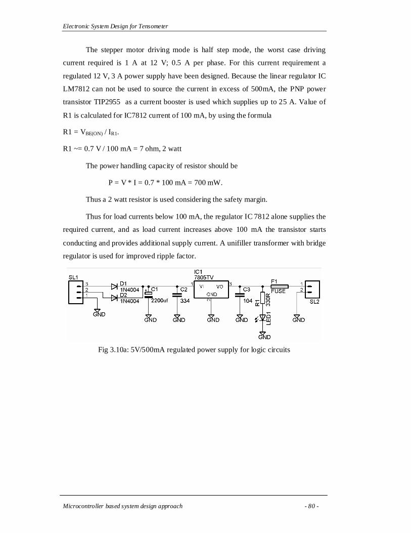
The stepper motor driving mode is half step mode, the worst case driving
current required is 1 A at 12 V; 0.5 A per phase. For this current requirement a
regulated 12 V, 3 A power supply have been designed. Because the linear regulator IC
LM7812 can not be used to source the current in excess of 500mA, the PNP power
transistor TIP2955 as a current booster is used which supplies up to 25 A. Value of
R1 is calculated for IC7812 current of 100 mA, by using the formula
R1 = VBE(ON) / IR1.
R1 ~= 0.7 V / 100 mA = 7 ohm, 2 watt
The power handling capacity of resistor should be
P = V * I = 0.7 * 100 mA = 700 mW.
Thus a 2 watt resistor is used considering the safety margin.
Thus for load currents below 100 mA, the regulator IC 7812 alone supplies the
required current, and as load current increases above 100 mA the transistor starts
conducting and provides additional supply current. A unifiller transformer with bridge
regulator is used for improved ripple factor.
Fig 3.10a: 5V/500mA regulated power supply for logic circuits

Electronic System Design for Tensometer
Microcontroller based system design approach - 81 -
Fig 3.10b: 12V/3A regulated power supply for stepper motor
MCT2E specs:
Input: forward current (max) : 60 mA
Forward voltage (typ. @ IF = 20 mA) : 1.1 V
Output: collector current (max) : 50 mA
Collector-emitter breakdown voltage (VCEO) : 70V
Coupler: Isolation test voltage VISO : 5300 VRMS
Isolation resistance : 1012 ohm
DC Current Transfer Ratio @ VCE= 10 V, IF = 10 mA : 60 %
MJE3055 specs:
Collector Current (IC max) : 10 A
Collector-Emitter Voltage VCEO max : 60 V
DC Current Gain (hFE) : 100
Thermal Resistance Junction-case Rthj-case (max) : 1.66 C/W
Operating Junction Temperature Tj (max) : 150 C
Total Power Dissipation at Tcase ≤ 25oC : 75W

Electronic System Design for Tensometer
Microcontroller based system design approach - 82 -
3.6.2 Driver circuit: [14,15]
Moholkar et. al. [14] have used a simple stepper motor driver without any
isolation. The system incorporated a mechanical setup for thin-film spray pyrolysis
instrument. The instrument was equipped with a stepper motor coupled belt-drive
based motion control system which carries spray nozzle over the film substrate. Motor
driver circuit was configured around the MOSFET IRF540 directly driven by a
microcontroller port outputs, without any isolation. The system could suffer from
poor reliability, because of presence of noise in the low power digital circuits. A
better alternative could be an optically isolated stepper motor driver with separate
power supply.
The stepper motor being a high power inductive load, creates noise on the
power supply lines. The low power microcontroller based logic circuitry requires
highly stable power supply to be operated correctly. This logic circuitry may get
disturbed by the power supply disturbances and may produce unpredictable results.
To avoid this situation the power supplies and the power supply lines viz. VCC/VSS
and VEE/VDD for the stepper motor driver and the low power logic circuitry have been
kept separate. In this situation these two circuits have to be interfaced via an
optocoupler, which provides complete electrical isolation. Optocouplers are suitable
for both high power DC and AC interfacing of circuits. A wide variety of
optocouplers is available to the circuit designers; transistor-output, thyristor-output,
etc. A transistor-output optocoupler MCT2E has been selected for the purpose of
interfacing the stepper motor driver to the microcontroller. The transfer characteristic
of this optocoupler is shown in the fig 3.10. The MCT2E optocoupler provides
isolation of 5300 V and requires a driving current of 20 mA for input LED. The
microcontroller port pin can not sink/source 20 mA, and thus a simple transistor
switch is added to the circuit.
Fig 3.11: MCT2E optocoupler transfer characteristics

Electronic System Design for Tensometer
Microcontroller based system design approach - 83 -
The output side of the optocoupler is operated at 12 V, and drives the stepper
motor driver NPN power transistor MJE3055. The output transistor from the
optocoupler and MJE3055 forms a darlington pair to boost the current to the required
level. A free-wheeling diode 1N4004 is added to the circuit to protect the transistors
from back-kick of the motor winding inductors. The fig 3.12A-B shows the schematic
of the stepper motor driver.
Fig 3.12a: Stepper motor driver

Electronic System Design for Tensometer
Microcontroller based system design approach - 84 -
Fig. 3.12b: Stepper motor driver – MOSFET power stage

Electronic System Design for Tensometer
Microcontroller based system design approach - 85 -
3.7 Optical sensor arrangement
The optical sensor arrangement is shown in the figure 3.13a. It includes a total five
pairs of IR receivers and transmitters (R-T pairs). Two IR R-T pairs are placed at the
two boundaries of the track distance. The carriage moves within these boundaries, the
motion of which has been controlled by supplying appropriate pulses to the stepper
motor which is coupled to the screw. One end of this arrangement has been
considered as an origin and the other one is the end of the scope. The carriage always
starts from the origin and tracks toward the endpoint. The carriage holds three
receivers; central lock-receiver, and the two left/right direction finder receivers. A
two/four quadrant sensor arrangement is also possible for improved precision. The
tensometer arm holds the IR transmitters which act as a reference for the three
receivers placed on the carriage. The direction finder receivers and the respected IR
transmitters have been arranged such that they get slightly offset when the central
lock IR pair is in unison. This arrangement is shown in figure 3.13b. The offset is kept
less than the resolution of the linear motion tracking system. When the tensometer
arm moves in either direction, the central lock receiver loses the signal, whilst the
corresponding direction finder receiver gets aligned with the transmitter. This leads
the system to track in the respective direction to achieve central lock again.

Electronic System Design for Tensometer
Microcontroller based system design approach - 86 -
Fig. 3.13a: Optical sensor arrangement
Fig. 3.13b: Optical sensor arrangement
When powered and reset the microcontroller first brings the carriage to the
‘origin’ position with the help of motion control system. When set to track the
tensometer arm it starts moving the carriage from the ‘origin’ towards the endpoint to
track and lock the tensometer arm. Once locked it continuously tracks and locks the
tensometer arm with the help of these three (lock, and direction finder) receivers. If
the tensometer arm is moved out of bounds defined by the endpoint receiver, the
microcontroller flags the error and brings the carriage back to the ‘origin’ position.
IR T
ransm
itters
IR R
eceive
rsTe
nsiom
eter
arm
mot
ion
Line
ar tr
ackin
g mot
ion
Scopebegin receiver
Scope endreceiver
Direction finder receivers
Central lock receiver
IR T
ransm
itters
IR R
eceive
rsTe
nsiom
eter
arm
mot
ion
Line
ar tr
ackin
g mot
ion
Scopebegin receiver
Scope endreceiver
Direction finder receivers
Central lock receiver
Direction finder receivers
Central lock receiver

Electronic System Design for Tensometer
Microcontroller based system design approach - 87 -
3.8 Firmware design: [16-24]
The system software design approach focuses on two main aspects: 1) code
size, as the microcontroller based systems have limited memory storage, and 2) the
development platform, the language and the software development tools with the
support for rapid application development. The assembly language, being closely
related to the underlying hardware platform, generates very small code for any
application, but becomes very hard to program and maintain as the software size
grows. On the other hand, the higher level languages, such as C can provide rapid
application development by directly replicating the human thinking into the source
code. But they need to compromise with the final program code size resulted. But
with the continual developments and modifications, the modern compiler writers
claim that the code resulted from their C compiler will no larger than 1.6 times that of
the equivalent assembly language code. The added advantage of C language is that it
also supports embedding the assembly code within the C code. Thus considering the
additional advantages and flexibility of the higher level languages C seems to be a
better choice for the firmware development for microcontrollers. Wherever required
assembly code can be included inline with the C source code.
The firmware development is divided into two sections; 1) writing and
debugging library files for individual components of the system; viz. LCD, stepper
motor, etc. and 2) combining all these libraries and making them work together.
The library files for the system include LCD drier, ‘lcd.h’ and stepper motor
control routines, ‘drive.h’. In addition to these files the defines.h file provides
information about I/O port mapping for various interfaces as well as user defined
function prototypes. The hardware definitions include mapping of stepper motor,
sensors and LCD interconnections to port pins. The software definitions include the
function prototypes for those functions, which require global scope in the program.
The separate library files make the software easy for debug and modify.

Electronic System Design for Tensometer
Microcontroller based system design approach - 88 -
3.8.1 ‘mcs.c’ – the main program file
The main program starts with initialization of the system, which includes
initialization of I/O ports and LCD. Port initialization defines port pin directions as
per the sensor, stepper motor and LCD interfacing requirements. It is followed by
LCD initialization, which resets and initializes the LCD module. The initialization
command sequence sent to LCD and their meaning is described in table 3.5:
Table 3.6:- LCD initialization commands
Command Description
0X28 Set interface data length = 4 bit; number of display lines
= 2, and character font = 5x7 dots
0X0C Set display ON; set cursor and cursor blinking OFF
0X06 Set cursor move direction to ‘incrementing’ the address
when data is sent to LCD.
0X01 Clear entire display and return cursor to home position
The initialization routine is followed by the track( ) routine, which performs
the two tasks: drive and track. This routine is an endless routine; i.e. it executes major
part of its body in a superloop. The major tasks performed by this routine are listed
below:
1) Check whether the carriage is at the starting point, ‘origin’. If not drive the motor
to bring it at the ‘origin’, then make the step counter zero and display the
displacement equal to zero.
2) Wait for the start switch input, when asserted start tracking for the tensometer
arm, until lock is acquired.
3) If lock is not acquired and end-scope boundary is detected, flag error condition
and return the carriage to the origin for the next go.
4) When the lock is acquired, keep tracking within the specified scope with the help
of direction finder sensors. If the tensometer arm goes out of bounds, bring the
carriage to the origin position and start over again.

Electronic System Design for Tensometer
Microcontroller based system design approach - 89 -
The track routine makes call to various routines viz. drive( ), decode( ), delay()
and the two error checking routines to test for the two boundaries: start
(error_origin()) and end (error_end()). The decode( ) routine converts the step-count
value into the displacement and sends the resulting data to the LCD display routine
for displaying it onto the LCD display. The delay( ) routine decides the stepper motor
stepping speed. The delay count can be adjusted as required for a stepper motor type.
The speed is constant in this case, but it can be varied if required by modifying the
count manually. The error checking routines error_origin() and error_end() use the
scope sensors to detect possible out-of-bounds travel of the tensometer arm, and flag
the error accordingly using audio buzzer as well as error message. These routines also
restart the tracking operation by first moving the carriage to the origin position.

Electronic System Design for Tensometer
Microcontroller based system design approach - 90 -
-------------------------------------------------------------
mcs1.c – Main program for motion control system
-------------------------------------------------------------
#include <REGX51.H>
#include <stdio.h>
#include <intrins.h>
#include "defines.h"
#include "lcd1.h"
#include "drive.h"
unsigned long int counter = 0;
void decode(unsigned long int);
void main(void)
{
void init(void);
void track(void);
init(); /*Initialize the system*/
track(); /*switch control to track routine - superloop*/
}
/*------------------------------------------*/
void track(void)
{
void error_origin(void);
void error_end(void);

Electronic System Design for Tensometer
Microcontroller based system design approach - 91 -
/*Bring carriage at the origin*/
while(origin)
drive(left);
counter = 0; /*Make counter 0 at origin*/
decode(counter); /*Decode position and display*/
while(start_sw); /*Wait for START switch*/
while(lock_led && endscope) /*Drive until get locked */
{
drive(right);
error_end(); /*End scope arrived, flag error */
};/*locked now keep tracking*/
while(1)
{
if(lock_led && !left_led) /*if carriage moved towards left*/
{
while(lock_led && origin)
drive(left); /*drive towards left until locked*/
}
if(lock_led && !right_led) /*if carriage moved towards left*/
{
while(lock_led && endscope)
drive(right); /*drive towards right until locked*/
}
error_origin(); /*carriage arrived at origin, flag scope error*/

Electronic System Design for Tensometer
Microcontroller based system design approach - 92 -
error_end(); /*carriage arrived at end, flag scope error*/
}
}
/*------------------------------------------*/
void error_origin(void)
/*if origin reached, flag error and restart tracking towards end scope*/
{
unsigned int a;
if(!origin)
{
display("Origin Reached ", 2,1);
buzzer = 1; /*audio warning*/
for(a=0;a<50000;a++);
buzzer = 0;
counter = 0;
display(" ", 2,1);
while(lock_led) /*retry to lock*/
{
drive(right);
error_end();
};
}
}
/*------------------------------------------*/
void error_end(void)
/*if end scope reached, flag error and bring carriage at origin */

Electronic System Design for Tensometer
Microcontroller based system design approach - 93 -
{
unsigned int a;
if(!endscope)
{
display("Endpoint Reached", 2,1);
buzzer = 1; /*audio warning*/
for(a=0;a<50000;a++);
buzzer = 0;
while(origin)
{
drive(left);
} /*Bring carriage to origin*/
counter = 0;
display(" ", 2,1);
}
}
/*------------------------------------------*/
void delay(void)
{
unsigned int i;
for(i=0;i<25000;i++);
}
/*-----------------------------------------*/
void init(void)
/*System initialize routine*/
{

Electronic System Design for Tensometer
Microcontroller based system design approach - 94 -
origin = 1; //define port i/o's----|
endscope = 1;
lock_led = 1;
left_led = 1;
right_led = 1;
start_sw = 1;
buzzer = 0; //------------------------|
myport = myort & 0x0f0; //clear lower nibble
len = 0; //disable lcd module
delay();
init_lcd(); //initialize lcd module
delay();
}
/*-----------------------------------------*/
void decode(unsigned long int i)
/*decode count and display*/
{
char c[10];
sprintf(c,"%10lu",i); /*convert long int to string for display*/
display("Count=", 1, 1);
display(c, 1, 7);
}
/*-----------------------------------------
Program Size: data=55.2 xdata=0 code=1939
-----------------------------------------*/

Electronic System Design for Tensometer
Microcontroller based system design approach - 95 -
3.8.2 Library files:
3.8.2.1 ‘defines.h’
This file contains the specifications of circuit interconnections for LCD,
stepper motor and sensors. The user defined function prototypes are also declared in
the same file. Inclusion of this file helps programmer to easily identify the circuit
configuration, which is very much useful in future expansion of the system.
--------------------------------
Defines.h
--------------------------------
#define MYPORT P1 // stepper motor connected to P1.0-P1.3
#define right 1
#define left 0
#define origin P2_0 //sensor connections
#define endscope P1_4
#define lock_led P1_5
#define left_led P1_6
#define right_led P1_7
#define buzzer P2_1
#define start_sw P2_2
#define lcd_data P0 //LCD connections
#define lrs P2_4
#define lrw P2_5
#define len P2_6
#define busy P0_3
void lready(void); //function prototypes
void lcommand(unsigned char);
void ldata(unsigned char);

Electronic System Design for Tensometer
Microcontroller based system design approach - 96 -
void init_lcd(void);
void delay(void);
--------------------------------
3.8.2.2 ‘lcd.h’
The LCD library provides functions for sending commands (control words) to
the LCD module, sending character/string data for display, testing for busy status, and
initializing LCD module. The three primary routines viz. send_command(),
send_data() and busy() are based on the waveforms shown in the fig 3.14. The
waveforms are self-explanatory; when enabled (EN = 1) the LCD module reads the
RS and RW control signals to identify the mode of operation. When RS = 0; the
control/status register is selected, else data register is selected, for writing (RW=0) /
reading (RW=1). As specified in the hardware section the LCD module can be
operated either in 8-bit mode or 4-bit mode. For current design it is used in 4-bit mode
to save on pin count, so that some pins can be left over for possible future expansion
of the system.
In addition to the three primary routines, this file also provides functions for
initializing LCD module - init_lcd() and displaying the character sequence at a
specified position - display(). The init_lcd() routine configures the LCD module as
specified in the table no. 3.5. The routine should be called once at the beginning of the
main program, before transferring the data to LCD module for display. The display()
routine can be called any time once the LCD module is initialized. Its syntax is as
follows:
void display(unsigned char * text, unsigned char line, unsigned char column)
It takes three parameters: a character string to be displayed, the line number and the
column number where the string is to be displayed. The routine does not check for the
size of the string, thus care should be taken while sending longer strings to the
routine. The largest string that can be sent to the routine will be 16 characters long,
when the column 1 is selected as the beginning of string. On the other hand if the
column number 16 is selected as the beginning of the string, then the string should be
only 1 character long.

Electronic System Design for Tensometer
Microcontroller based system design approach - 97 -
Fig. 3.14a: 16x2 LCD module read operation
Fig. 3.14b: 16x2 LCD module write operation

Electronic System Design for Tensometer
Microcontroller based system design approach - 98 -
--------------------------------
‘lcd.h’
--------------------------------
/*4-bit lcd interface*/
/*Generate delay by introdufing 'n' NOP instructions*/
void _nops(unsigned char n)
{
for(;n>0;n--)
_nop_();
}
/*Initialize LCD*/
void init_lcd(void)
{
lcommand(0x28); //4bit interface, two lines, 5x7 font
lcommand(0x0c); //display ON, cursor and cursor blinking OFF
lcommand(0x06); //cursor auto-increment
lcommand(0x01); //clear LCD, home cursor
}
/*Wait until LCD is ready*/
void lready(void)
{
busy = 1;
lrs = 0;
lrw = 1;

Electronic System Design for Tensometer
Microcontroller based system design approach - 99 -
_nops(100);
do
{
len = 0;
_nops(100);
len = 1;
nops(25);
}while(busy); /*clock LCD enable pin and poll LCD status*/
len = 0;
_nops(100);
}
/*Send command word to LCD, 4 bits at a time*/
void lcommand(unsigned char c)
{
lready(); /*Wait until LCD is ready*/
lcd_data = lcd_data & 0x0f0;
lcd_data = lcd_data | c >> 4; /*send higher nibble first*/
lrs = lrw = 0;
_nops(100);
len = 1;
_nops(100);
len = 0;
_nops(100);
lcd_data = lcd_data & 0x0f0;

Electronic System Design for Tensometer
Microcontroller based system design approach - 100 -
lcd_data = lcd_data | (c & 0x0f); /*send lower nibble*/
lrs = lrw = 0;
_nops(100);
len = 1;
_nops(100);
len = 0;
_nops(100);
}
/*Send data for display on LCD, 4-bits at a time*/
void ldata(unsigned char c)
{
lready(); /*Wait until LCD is ready*/
lcd_data = lcd_data & 0x0f0;
lcd_data = lcd_data | c >> 4; /*send higher nibble first*/
lrs = 1;
lrw = 0;
_nops(100);
len = 1;
_nops(100);
len = 0;
_nops(100);
lcd_data = lcd_data & 0x0f0;
lcd_data = lcd_data | (c & 0x0f); /*send lower nibble*/
lrs = 1;

Electronic System Design for Tensometer
Microcontroller based system design approach - 101 -
lrw = 0;
_nops(100);
len = 1;
_nops(100);
len = 0;
_nops(100);
}
/*Send text to LCD for display on specified position*/
/* text = any string (max 16 characters)
line = 1 or 2, column = 1 - 16
*/
void display(unsigned char * text, unsigned char line, unsigned char column)
{
unsigned char i=0;
switch(line) /*Select display line 1 or 2*/
{
case 1: lcommand(0x80+column-1);
break;
case 2: lcommand(0x0c0+column-1);
}
while(1) /*Send text for display*/
{
if(text[i] == '\0')
break;
ldata(text[i]);

Electronic System Design for Tensometer
Microcontroller based system design approach - 102 -
i++;
}
}
3.8.2.3 ‘drive.h’
The drive( ) routine is a part of drive.h library file. This routine takes direction
field as an input parameter and according to the direction it sends the proper wave
drive sequence to drive the motor in specified direction and updates the counter
accordingly. It also maintains a counter of number of steps carried out while tracking
in either direction.
--------------------------------
drive.h
--------------------------------
#include "defines.h"
void delay(void);
void decode(unsigned long int);
extern unsigned long int counter;
static unsigned char i=0;
unsigned char half_step[] = {3,2,6,4,0x0c,8,9,1}; /*half stepping method*/
void drive(bit direction) /*drive motor in specified direction*/
{
unsigned int a=0;
if(direction == right)
{
i++;
counter++;

Electronic System Design for Tensometer
Microcontroller based system design approach - 103 -
decode(counter);
if(i>7)
i=0;
MYPORT &= 0xf0;
MYPORT |= half_step[i] & 0x0f;
}
else
{
i--;
counter--;
decode(counter);
if(i== 0x0ff)
i=7;
}
delay();
}

Electronic System Design for Tensometer
Microcontroller based system design approach - 104 -
3.9 Observations:
Table 3.7 shows the firmware footprints developed using two platforms; CISC
platform consisting of Keil-MCS51 and RISC platform consisting of WINAVR-AVR.
The CISC platform proves to be better than the RISC in terms of code density.
Table 3.7 Firmware footprints
Design platform Code memory Data memory
Keil-MCS51 1939 bytes 55 bytes, 2 bits
WINAVR-AVR 4448 words (16 bit) 40 bytes
Table 3.8 shows linear displacement of the table in response to the input
pulses to the stepper motor. The maximum linear travel scope is 18 cm, which has
been approached after 7200 pulses when the motor has been driven using full step
wave drive. Alternatively when driven using half stepping drive method the same
system provided double precision, and required double the pulses to arrive at the end
scope.
Table 3.8 Linear travel versus number of steps
Linear travel (mm) Number of
input steps Full Stepping Half Stepping
200 5.0 2.5
400 10.0 5.0
600 15.0 7.5
800 20.0 10.0
1000 25.0 12.5
1200 30.0 15.0
2000 32.5 16.3
3000 75.0 37.5
4000 100.0 50.0
5000 125.0 62.5
6000 150.0 75.0
7000 175.0 87.5

Electronic System Design for Tensometer
Microcontroller based system design approach - 105 -
7200 180.0 90.0
8000 NA 100.0
9000 NA 112.5
10000 NA 125.0
11000 NA 137.5
12000 NA 150.0
13000 NA 162.5
14000 NA 175.0
14400 NA 180.0
15000 NA NA
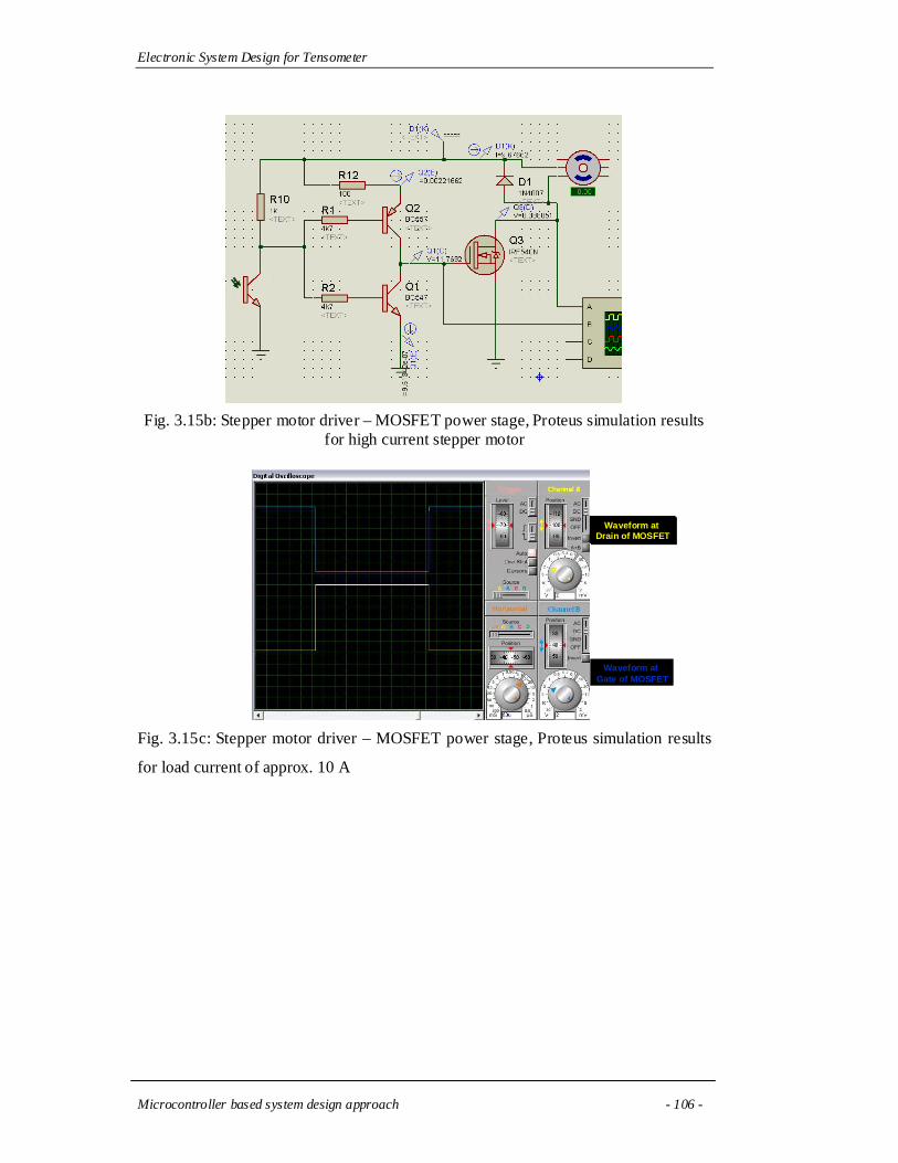
The Proteus simulation results have been shown in fig 3.15A-C. Fig. 3.15A
shows the driving results for STM601 stepper motor. The motor draws 500 mA per
phase current from the power supply, which has been easily handled by the MOSFET
driver IRF540N. The same driver circuit has also been tested for load current of about
10 A as shown in fig. 3.15B. The waveforms at the gate and drain terminals of the
MOSFET have been shown in fig 3.15C. It is clearly evident from the waveforms that
the circuit supplies precise square wave driving signal to the stepper motor, even at
driving current of 10 A.
Fig. 3.15a: Stepper motor driver – MOSFET power stage, Proteus simulation results for STM601 stepper motor
Electronic System Design for Tensometer
Microcontroller based system design approach - 106 -
Fig. 3.15b: Stepper motor driver – MOSFET power stage, Proteus simulation results for high current stepper motor
Fig. 3.15c: Stepper motor driver – MOSFET power stage, Proteus simulation results
for load current of approx. 10 A
Waveform at Drain of MOSFET
Waveform at Drain of MOSFET
Waveform at Gate of MOSFET

Electronic System Design for Tensometer
Microcontroller based system design approach - 107 -
References:
[1] P.A. Kadam, G.G. Tengashe, S.R. Sawant, Growth of 8-Bit MCS51
familyMicrocontrollers – A Review, Journal of the Shivaji University (Science
and Technology), 39, 2005..
[2] K.J.Ayala, The 8051 micro-controller, Penram International Publishing
(India)-1996
[3] M.Predko, Programming and customizing the 8051 micro-controller, TMH-
2001
[4] Jan Axelson, The micro-controller idea book, Penram International
Publishing, (India)- 1997
[5] J. Stewart, The micro-controller 8051, PHI-1998
[6] Intel micro-controller handbook, Intel Corporation, 1984
[7] M.A.Mazidi and J.G.Mazidi, The 8051 micro-controller and embedded
systems, Pearson Education (Singapore), 2002.
[8] I. Scott MacKenzie, Raphael Chung-Wei Phan, The 8051 Microcontroller,
Prentice Hall, 4th edition – 2005.
[9] William Kleitz, Microprocessor and Microcontroller Fundamentals: The 8085
and 8051 Hardware and Software, Prentice Hall – 1997.
[10] D.Roy Choudhry, Shail Jain, “Linear Integrated Circuits”, New Age
International Pvt. Ltd., 2000.
[11] Ramakant A.Gayakwad, ‘OP-AMP and Linear IC’s’, Prentice Hall /
Pearson Education, 1994.
[12] William D.Stanely, ‘Operational Amplifiers with Linear Integrated
Circuits’. Pearson Education, 2004.
[13] B.S.Sonde, Power Supplies, Tata McGraw Hill, 1980. ISBN
10:0070966184
[14] S.M. Pawar, A.V. Moholkar, P.S. Shinde, K.Y. Rajpure and C.H.
Bhosale, Room temperature electrocrystallization of CdSe thin films from

Electronic System Design for Tensometer
Microcontroller based system design approach - 108 -
ethylene glycol bath, Journal of Alloys and Compounds, Volume 459, Issues
1-2, 14 July 2008, Pages 515-520
[15] P. Thimmaiah et. al., Design and development of an embedded system
for web camera control, Journal of Instrumentaion Society of India 36(2) 125-
132, 2006.
[16] Thomas W. Schultz, C and the 8051 Programming for Multitasking,
Simon & Schuster – 1992.
[17] Thomas W. Schultz, C and the 8051: Building Efficient Applications
(C and the 8051), PHI – 1999.
[18] Kirk Zurell, C Programming for Embedded Systems, R&D Books,
CMP Media, Inc.
[19] Gajski D.D., Vahid, F., 1995, Specification and design of embedded
hardware-software systems, Design & Test of Computers, IEEE, Volume: 12,
Issue: 1, 53-67, ISSN: 0740-7475
[20] Fei Xie, Guowu Yang, and Xiaoyu Song, 2007, Component-based
hardware/software co-verification for building trustworthy embedded systems,
Journal of Systems and Software,Volume 80, Issue 5, Pages 643-654
[21] Michael J. Pont , and Mark P. Banner, 2004, Designing embedded
systems using patterns: A case study, Journal of Systems and Software,
Volume 71, Issue 3, Pages 201-213, Computer Systems
[22] J. E. Cooling, 1996, Languages for the programming of real-time
embedded systems a survey and comparison, Microprocessors and
Microsystems, Volume 20, Issue 2, Pages 67-77
[23] David O Williams, 1987, Language requirements for embedded
systems, Computer Standards & Interfaces, Volume 6, Issue 1, Pages 51-60,
Real-time Distributed Software
[24] Kenneth J. Hintz, 1992, Merging C and assembly language in
microcontroller applications, Journal of Microcomputer Applications, Volume
15, Issue 3, Pages 267-278

Electronic System Design for Tensometer
Microcontroller based system design approach - 109 -
+Online References:
[1] PCF8583 - Clock/calendar with 240 x 8-bit RAM, NXP semiconductors,
http://www.nxp.com/#/pip/pip=[pip=PCF8583_5]|pp=[t=pip,i=PCF8583_5], visited
22-1-2009
[2] 2-Wire Bus Serial EEPROM with full memory Write Protect, supports up to 8
devices on single 2-Wire bus,
http://www.atmel.com/dyn/products/devices.asp?family_id=647#1573, visited 22-1-
2009
[3] LCD displays, Vishay Electronics, http://www.vishay.com/displays/lcd/, visited
22-1-2009
[4] 16 by 2 Alphanumeric LCD Module, Embedded Results Ltd,
http://www.kanda.com/datasheet/11-11-2008-1637lcd-module.pdf, visited 22-1-2009