chapter five traffic controls - tewodros · pdf filechapter five . traffic controls . ... the...
TRANSCRIPT

. AAIT, Civil Engineering Department Transportation Engineering (CE 485)
Department of Civil Engineering, AAiT Page | 1
Chapter Five
Traffic Controls
Traffic control devices are the media by which traffic engineers communicate with drivers.
Virtually every traffic law, regulation, or operating instruction must be communicated
through the use of devices that fall into three broad categories:
• Traffic markings
• Traffic signs
• Traffic signals
The effective communication between traffic engineer and driver is a critical link if safe
and efficient traffic operations are to prevail. Traffic engineers have no direct control over any
individual driver or group of drivers. If a motorman violated a RED signal while conducting a
subway train, an automated braking system would force the train to stop anyway. If a driver
violates a RED signal, only the hazards of conflicting vehicular and/or pedestrian flows would
impede the maneuver. Thus, it is imperative that traffic engineers design traffic control devices
that communicate uncomplicated messages clearly, in a way that encourages proper
observance.
The driver is accustomed to receiving a certain message in a clear and standard fashion,
often with redundancy. A number of mechanisms are used to convey messages. These
mechanisms make use of recognized human limitations, particularly with respect to eyesight.
Messages are conveyed through the use of:
• Color. Color is the most easily visible characteristic of a device. Color is recognizable
long before a general shape may be perceived and considerably before a specific
legend can be read and understood. The principal colors used in traffic control
devices are red, yellow, green, orange, black, blue, and brown. These are used to
code certain types of devices and to reinforce specific messages whenever possible.
• Shape. After color, the shape of the device is the next element to be discerned by
the driver. Particularly in signing, shape is an important element of the message,
either identifying a particular type of information that the sign is conveying or
conveying a unique message of its own.

. AAIT, Civil Engineering Department Transportation Engineering (CE 485)
Department of Civil Engineering, AAiT Page | 2
• Pattern. Pattern is used in the application of traffic markings. In general, double solid,
solid, dashed, and broken lines are used. Each conveys a type of meaning with which
drivers become familiar. The frequent and consistent use of similar patterns in similar
applications contributes greatly to their effectiveness and to the instant recognition of
their meaning.
• Legend. The last element of a device that the driver comprehends is its specific
legend. Signals and markings, for example, convey their entire message through use of
color, shape, and pattern. Signs, however, often use specific leg- end to transmit the
details of the message being transmitted. Legend must be kept simple and short, so
that drivers do not divert their attention from the driving task, yet are able to see and
understand the specific message being given.
This chapter introduces some of the basic principles involved in the design and placement of
traffic controls with reference of MUTCD [Manual on Uniform Traffic Control Devices]
standards.
5.1 Traffic Markings Traffic markings are the most plentiful traffic devices in use. They serve a variety of purposes and functions and fall into three broad categories:
• Longitudinal markings
• Transverse markings
• Object markers and delineators
Longitudinal and transverse markings are applied to the roadway surface using a variety
of materials, the most common of which are paint and thermoplastic. Reflectorization for
better night vision is achieved by mixing tiny glass beads in the paint or by
applying a thin layer of glass beads over the wet pavement marking as it is placed. The
latter provides high initial reflectorization, but the top layer of glass beads is more
quickly worn. When glass beads are mixed into the paint before application, some level of
reflectorization is preserved as the marking wears.

. AAIT, Civil Engineering Department Transportation Engineering (CE 485)
Department of Civil Engineering, AAiT Page | 3
5.1.1 Longitudinal Markings
Longitudinal markings are those markings placed parallel to the direction of travel. The
vast majority of longitudinal markings involve centerlines, lane lines, and pavement edge
lines. Longitudinal markings provide guidance for the placement of vehicles on the
traveled way cross-section and basic trajectory guidance for vehicles traveling along the
facility. The best example of the importance of longitudinal markings is the difficulty in
traversing a newly paved highway segment on which lane markings have not yet been
repainted. Drivers do not automatically form neat lanes without the guidance of
longitudinal markings; rather, they tend to place themselves somewhat randomly on the
cross-section, encountering many difficulties. Longitudinal markings provide for
organized flow and optimal use of the pavement width.
Centerlines
Centre line separates the opposing streams of traffic and facilitates their movements.
Usually no centre line is provided for roads having width less than 5 m and for roads
having more than four lanes. The centre line may be marked with either single broken line,
single solid line, double broken line, or double solid line depending upon the road and traffic
requirements. On urban roads with less than four lanes, the centre line may be single broken
line segments of 3 m long and 150 mm wide. The broken lines are placed with 4.5 m gaps
(figure 5.1).
Figure 5.1: Centre line marking for a two lane road
On two-lane, two-way rural highways, centerline markings supplemented by signs are used to
regulate passing maneuvers. A double-solid yellow center marking indicates that passing is
not permitted in either direction. A solid yellow line with a dashed yellow line indicates that
passing is permitted from the dashed side only. Where: passing is permissible in both
directions, a single dashed yellow centerline is used.

. AAIT, Civil Engineering Department Transportation Engineering (CE 485)
Department of Civil Engineering, AAiT Page | 4
Lane Markings
The typical lane marking is a single white dashed line separating lanes of traffic in the same
direction. MUTCD standards require the use of lane markings on all free- ways and Interstate
highways and recommend their use on all highways with two or more adjacent traffic lanes in
a single direction. The dashed lane line indicates that lane changing is permitted. A single
solid white lane line is used to indicate that lane-changing is discouraged but not illegal.
Where lane-changing is to be prohibited, a double-white solid lane line is used.
Figure 5.2: Centre line and lane marking for a four lane road
Figure 5.3: Double solid line for a two lane road
Edge Markings
Edge lines indicate edges of rural roads which have no curbs to delineate the limits up to
which the driver can safely venture. They should be at least 150 mm from the actual
edge of the pavement. They are painted in yellow or white.
All the lines should be preferably light reflective, so that they will be visible during night
also. Improved night visibility may also be obtained by the use of minute glass beads
embedded in the pavement marking materials to produce a retroreflective surface.
. AAIT, Civil Engineering Department Transportation Engineering (CE 485)
Department of Civil Engineering, AAiT Page | 5
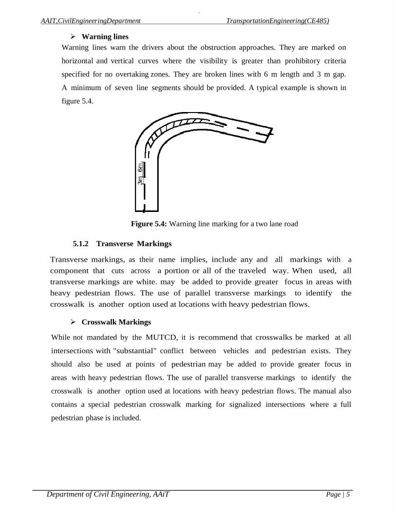
Warning lines Warning lines warn the drivers about the obstruction approaches. They are marked on
horizontal and vertical curves where the visibility is greater than prohibitory criteria
specified for no overtaking zones. They are broken lines with 6 m length and 3 m gap.
A minimum of seven line segments should be provided. A typical example is shown in
figure 5.4.
Figure 5.4: Warning line marking for a two lane road
5.1.2 Transverse Markings Transverse markings, as their name implies, include any and all markings with a component that cuts across a portion or all of the traveled way. When used, all transverse markings are white. may be added to provide greater focus in areas with heavy pedestrian flows. The use of parallel transverse markings to identify the crosswalk is another option used at locations with heavy pedestrian flows.
Crosswalk Markings
While not mandated by the MUTCD, it is recommend that crosswalks be marked at all
intersections with "substantial" conflict between vehicles and pedestrian exists. They
should also be used at points of pedestrian may be added to provide greater focus in
areas with heavy pedestrian flows. The use of parallel transverse markings to identify the
crosswalk is another option used at locations with heavy pedestrian flows. The manual also
contains a special pedestrian crosswalk marking for signalized intersections where a full
pedestrian phase is included.

. AAIT, Civil Engineering Department Transportation Engineering (CE 485)
Department of Civil Engineering, AAiT Page | 6
Figure 5.5: Pedestrian marking near an intersection
Parking Space Markings
Parking space markings are not purely transverse, as they contain both longitudinal and
transverse elements. They are officially categorized as transverse markings, however, in the
MUTCD. They are always optional and are used to encourage efficient use of parking
spaces. Such markings can also help prevent encroachment of parked vehicles into fire
hydrant zones, loading zones, taxi stands and bus stops, and other specific locations at
which parking is prohibited. They are also useful on arterials with curb parking, as they
also clearly demark the parking lane, separating it from travel lanes. Figure 5.6
illustrates typical parking lane markings.
Figure 5.6: Typical Parking Space Markings

. AAIT, Civil Engineering Department Transportation Engineering (CE 485)
Department of Civil Engineering, AAiT Page | 7
Directional arrows
In addition to the warning lines on approaching lanes, directional arrows should be used to
guide the drivers in advance over the correct lane to be taken while approaching busy
intersections. Because of the low angle at which the markings are viewed by the drivers, the
arrows should be elongated in the direction of traffic for adequate visibility. The dimensions of
these arrows are also very important.
Figure 5.7 A typical example of a directional arrow
Word and Symbol Markings
The MUTCD prescribes a number of word and symbol markings that may be used, often in
conjunction with signs and/or signals. These include arrow markings indicating lane-use
restrictions. Such arrows (with accompanying signs) are mandatory where a through lane
becomes a left- or right-turn-only lane approaching an intersection.
Word markings include "ONLY" used in conjunction with lane use arrows, and "STOP" which
can be used only in conjunction with a STOP line and a STOP sign. "SCHOOL" markings are
often used in conjunction with signs to demark school and school-crossing zones. The MUTCD
contains a listing of all authorized word markings and allows for discretionary use
of unique messages where needed.
5.1.3 Object Markers
Object markers are used to denote obstructions either or adjacent to the traveled
way. There are three types of object markers used, as illustrated in Figure below. Obstructions
within the roadway must be marked using a Type 1 or Type 3 marker. The Type 3 marker,
when used, must have the alternating yellow and black stripes sloped downward at a 45° angle
towards the side on which traffic is to pass the obstruction. When used to mark a roadside
obstruction, the inside edge. of the marker must be in line with the inner edge of the obstruction.

. AAIT, Civil Engineering Department Transportation Engineering (CE 485)
Department of Civil Engineering, AAiT Page | 8
Typical Type 1 Object Markers
Nine yellow retroreflectors with 3-in minimum diameter on a yellow or black
diamond panel of 18 in or more on a side; or an all-yellow retroreflective
diamond panel of the same size.
Typical Type 2 Object Markers
Three yellow retroreflectors with 3-in minimum diameter arranged horizontally
or vertically on white panel of at least 6 X 12 in; or an all- yellow retroreflective
panel of the same size.
Typical Type 3 Object Markers
A striped marker measuring 12 X 36 in with alternating black and yellow stripes
sloping downward at an angle of 45° toward the side of the obstruction on which
traffic is to pass.
5.2 Traffic Signs
In general, traffic signs fall into one of three major categories:
• Regulatory signs.
• Warning signs.
• Guide signs.

. AAIT, Civil Engineering Department Transportation Engineering (CE 485)
Department of Civil Engineering, AAiT Page | 9
5.2.1. Regulatory Signs
Regulatory signs shall be used to inform road users of selected traffic laws or regulations and
indicate the applicability of the legal requirements. Regulatory signs convey information
concerning specific traffic regulations. Regulations may relate to right-of-way, speed limits,
lane usage, parking, or a variety of other functions.
Regulatory signs shall be installed at or near where the regulations apply. The signs shall
clearly indicate the requirements imposed by the regulations and shall be designed and installed
to provide adequate visibility and legibility in order to obtain compliance.
Drivers are expected to be aware of many general traffic regulations, such as the basic right-of-
way rule at intersections and the state speed limit. Signs, however, should be used in all cases
where the driver cannot be expected to know the applicable regulation.
Except for some special signs, such as the STOP and YIELD sign, most regulatory signs are
rectangular, with the long dimension vertical. Some regulatory signs are square. These are
primarily signs using symbols instead of legend to impart information. The background color
of regulatory signs, with a few exceptions, is white, while legend or symbols are black. In
symbol signs, a red circle with a bar through it signifies a prohibition of the movement
indicated by the symbol.
Right of way series: These include two unique signs that assign the right of way to the
selected approaches of an intersection. They are the STOP sign and GIVE WAY sign For
example, when one minor road and major road meets at an intersection, preference should
be given to the vehicles passing through the major road. Hence the give way sign board will
be placed on the minor road to inform the driver on the minor road that he should give way for
the vehicles on the major road. In case two major roads are meeting, then the traffic engineer
decides based on the traffic on which approach the sign board has to be placed. Stop sign
is another example of regulatory signs that comes in right of way series which requires the
driver to stop the vehicle at the stop line.
Speed series: Number of speed signs may be used to limit the speed of the vehicle on the road.
They include typical speed limit signs, truck speed, minimum speed signs etc. Speed limit signs
are placed to limit the speed of the vehicle to a particular speed for many reasons. Separate
truck speed limits are applied on high speed roadways where heavy commercial vehicles
must be limited to slower speeds than passenger cars for safety reasons. Minimum speed limits

. AAIT, Civil Engineering Department Transportation Engineering (CE 485)
Department of Civil Engineering, AAiT Page | 10
are applied on high speed roads like expressways, freeways etc. where safety is again a
predominant reason. Very slow vehicles may present hazard to themselves and other vehicles
also.
Movement series: They contain a number of signs that affect specific vehicle maneuvers.
These include turn signs, alignment signs, exclusion signs, one way signs etc. Turn signs
include turn prohibitions and lane use control signs. Lane use signs make use of arrows to
specify the movements which all vehicles in the lane must take. Turn signs are used to safely
accommodate turns in unsignalized intersections.
Parking series: They include parking signs which indicate not only parking prohibitions
or restrictions, but also indicate places where parking is permitted, the type of vehicle to be
parked, duration for parking etc.
Pedestrian series: They include both legend and symbol signs. These signs are meant for the
safety of pedestrians and include signs indicating pedestrian only roads, pedestrian crossing
sites etc.
Miscellaneous: Wide variety of signs that are included in this category are: a "KEEP OF
MEDIAN" sign, signs indicating road closures, signs restricting vehicles carrying
hazardous cargo or substances, signs indicating vehicle weight limitations etc.
Figure 5.7: Examples of regulatory signs ( stop sign, give way sign, signs for no entry, sign
indicating prohibition for right turn, vehicle width limit sign, speed limit sign)
5.2.2. Warning Signs
Warning signs call attention to unexpected conditions on or adjacent to a highway or street
and to situations that might not be readily apparent to road users. Warning signs alert road
users to conditions that might call for a reduction of speed or an action in the interest of
safety and efficient traffic operations.

. AAIT, Civil Engineering Department Transportation Engineering (CE 485)
Department of Civil Engineering, AAiT Page | 11
Most warning signs are diamond-shaped, with black lettering or symbols on a yellow
background. A pennant shape is used for the "No Passing Zone" sign, used in conjunction
with passing restrictions on two- lane, two-way rural highways. A rectangular shape is
used for some arrow indications. A circular shape is used for railroad crossing warnings.
The MUTCD indicates that warning signs shall be used only in conjunction with an
engineering study or based on engineering judgment. While this is a fairly loose
requirement, it emphasizes the need to avoid over- use of such signs. A warning sign should be
used only to alert drivers of conditions that they could not be normally expected to discern on
their own. Overuse of warning signs encourages drivers to ignore them, which could lead to
dangerous situations.
When used, warning signs must be placed far enough in advance of the hazard to allow
drivers adequate time to perform the required adjustments. Warning signs may be used with
supplementary panels indicating either the distance to the hazard or an advisory speed. The
advisory speed is the recommended safe speed through the hazardous area and is determined
by an engineering study of the location. Warning signs are used to inform drivers of a
variety of potentially hazardous circumstances, including:
• Changes in horizontal alignment
• Intersections
• Advance warning of control devices
• Converging traffic lanes
• Narrow roadways
• Changes in highway design
• Grades
• Roadway surface conditions
• Railroad crossings
Figure 5.8: Examples of cautionary signs ( right hand curve sign board,
signs for narrow road, sign indicating railway track ahead)

. AAIT, Civil Engineering Department Transportation Engineering (CE 485)
Department of Civil Engineering, AAiT Page | 12
5.2.3. Guide/Informative/ Signs
Guide signs provide information to road users concerning destinations, available
services, and historical/recreational facilities. They serve a unique purpose in that
drivers who are familiar or regular users of a route will generally not need to use
them; they provide critical information, however, to unfamiliar road users. The
background varies by the type of information contained on the sign. Directional or
destination information is provided by signs with a green background; information
on services is provided by signs with a blue background; cultural, historical, and/or
recreational in- formation is provided by signs with a brown back- ground.
Route markers, included in this category, have varying shapes and colors depending
on the type and jurisdiction of the route.
The MUTCD provides guide-signing information for three types of facilities:
conventional roads, free- ways, and expressways. Guide signing is somewhat
different from other types in that overuse is generally not a serious issue, unless it
leads to confusion. Clarity and consistency of message is the most important
aspect of guide signing. Several general principles may be applied:
1. If a route services a number of destinations, the most important of these should be listed.
2. No guide sign should list more than three (four may be acceptable in some
circumstances) destinations on a single sign. This, in conjunction with the first
principle, makes the selection of priority destinations a critical part of effective
guide signing.
3. Where roadways have both a name and a route number, both should be indicated
on the sign if space permits. In cases where only one may be listed, the route
number takes precedence. Road maps show route numbers prominently, while
not all facility names are included. Unfamiliar drivers are, therefore, more
likely to know the route number than the facility name.
4. Wherever possible, advance signing of important junctions should be given. This
is more difficult on conventional highways, where junctions may be frequent and
closely spaced. On free- ways and expressways, this is critical, as high approach
speeds make advance knowledge of upcoming junctions a significant safety issue.
5. Wherever possible, advance signing of important junctions should be given. This
is more difficult on conventional highways, where junctions may be frequent and

. AAIT, Civil Engineering Department Transportation Engineering (CE 485)
Department of Civil Engineering, AAiT Page | 13
closely spaced. On free ways and expressways, this is critical, as high approach
speeds make advance knowledge of upcoming junctions a significant safety issue.
6. Confusion on the part of the driver must be avoided at all cost. Sign
sequencing should be logical and should naturally lead the driver to the desired
route selections. Overlapping sequences should be avoided wherever possible.
Left-hand exits and other unusual junction features should be signed extremely
carefully.
7. The size, placement, and lettering of guide signs vary considerably, and the
manual gives information on numerous options. A number of site-specific
conditions affect these design features, and there is more latitude and choice
involved than for other types of highway signs. The MUTCD should be consulted
directly for this information.
Figure 5.9: Examples of informative signs (route markers, destination signs,
mile posts, service centre information etc)
5.3 Traffic signal
The operation of signalized intersections is often complex, involving competing
vehicular and pedestrian movements. Appropriate methodologies for design and
timing of signals and for the operational analysis of signalized intersections require
that the behavior of drivers and pedestrians at a signalized intersection be modeled
in a form that can be easily manipulated and optimized.
Objectives of Signal Timing
The main objectives of signal timing at an intersection are to reduce the average delay
of all vehicles and the probability of accidents. These objectives are achieved by
minimizing the possible conflict points when assigning the right of way to different
traffic streams at different times. The objective of reducing delay, however,
sometimes conflicts with that of accident reduction. This is because the number of
distinct phases should be kept to a minimum to reduce average delay, whereas many

. AAIT, Civil Engineering Department Transportation Engineering (CE 485)
Department of Civil Engineering, AAiT Page | 14
more distinct phases may be required to separate all traffic streams from each other.
When this situation exists, it is essential that engineering judgment be used to
determine a compromise solution. In general, however, it is usual to adapt a two-
phase system whenever possible, using the shortest practical cycle length that is
consistent with the demand. At a complex intersection, though, it may be necessary to
use a multiphase (three or more phases) system to achieve the main design objectives.
Types of Signal Operation
Traffic signals can operate on a pretimed basis or may be partially or fully actuated by
arriving vehicles sensed by detectors. In networks, or on arterials, signals may be coordinated
through computer control.
1. Pretimed operation. In pretimed operation, the cycle length, phase sequence, and
timing of each interval are constant. Each cycle of the signal follows the same predetermined
plan. "Multi-dial" controllers will allow different pre- timed settings to be established. An
internal clock is used to activate the appropriate timing. In such cases, it is typical to have at
least an AM peak, a PM peak, and an off-peak signal timing.
2. Semi-actuated operation. In semi-actuated operation, detectors are placed on the minor
approach(es) to the intersection; there are no detectors on the major street. The light is green
for the major street at all times except when a "call" or actuation is noted on one of the
minor approaches. Then, subject to limitations such as a minimum major-street green, the
green is transferred to the minor street. The green returns to the major street when the
maximum minor- street green is reached or when the detector senses that there is
no further demand on the minor street.
3 . Full actuated operation. In full actuated operation, every lane of every approach must
be monitored by a detector. Green time is allocated in for capturing and retaining the green.
In full actuated operation, the cycle length, sequence of phases, and green time split may
vary from cycle to cycle.
4. Computer control. Computer control is a system term. No individual signal is
"computer controlled," unless the signal controller is considered to be a computer. In a
computer-controlled system, the computer acts as a master controller, coordinating the
timings of a large number (hundreds) of signals. The computer selects or calculates
an optimal coordination plan based on input from detectors placed through out the

. AAIT, Civil Engineering Department Transportation Engineering (CE 485)
Department of Civil Engineering, AAiT Page | 15
system. In general, such selections are made only once in advance of an AM or
PM peak period. The nature of a system transition from one timing plan to another is
sufficiently disruptive to be avoided during peak-demand periods. Individual
signals in a computer-controlled system generally operate in the pretimed mode. For
coordination to be effective, all signals in the network must use the same cycle
length (or an even multiple thereof), and it is therefore difficult to maintain a
progressive pat tern where cycle length or phase splits are allowed to vary.
Components of a Signal Cycle
The following terms describe portions and sub portions of a signal cycle. The
most fundamental unit in signal design and timing is the cycle, as defined below.
1. Cycle. A signal cycle is one complete rotation through all of the indications provided.
In general, every legal vehicular movement receives a "green" indication during each cycle,
although there are some exceptions to this rule.
2. Cycle length. The cycle length is the time (in seconds) that it takes to complete one full
cycle of indications. It is given the symbol "C."
3. Interval. The interval is a period of time during which no signal indication changes. It
is the smallest unit of time described within a signal cycle. There are several types of
intervals with- in a signal cycle:
(a) Change interval. The change interval is the "yellow" indication for a given
movement. It is part of the transition from "green" to "red," in which movements
about to lose "green" are given a "yellow" signal, while all other movements have a
"red" signal. It is timed to allow a vehicle that cannot safely stop when the "green"
is withdrawn to enter the intersection legally. The change interval is given the
symbol “i” for movement(s) i.
(b) Clearance interval. The clearance interval is also part of the transition from
"green" to "red" for a given set of movements. During the clearance interval, all
movements have a "red" signal. It is timed to allow a vehicle that legally enters the
intersection on "yellow" to safely cross the intersection before conflicting flows are
released. The clearance interval is given the symbol "ari” (for "all red") for
movement(s) i.
(c) Green interval. Each movement has one green interval during the signal
cycle. During
. AAIT, Civil Engineering Department Transportation Engineering (CE 485)
Department of Civil Engineering, AAiT Page | 16
a green interval, the movements permitted have a "green" light, while all other
movements have a "red" light. The green interval is given the symbol "Gi” for
movement(s) i.
(d) Red interval. Each movement has a red interval during the signal cycle. All
movements not permitted have a "red" light, while those permitted to move have a
"green" light. In general, the red interval overlaps the green intervals for all other
movements in the inter- section. The red interval is given the symbol "Ri” for
movement(s) i.
4. Phase. A signal phase consists of a green interval, plus the change and clearance
intervals that follow it. It is a set of intervals that allows a designated movement or set of
movements to flow and to be safely halted before release of a conflicting set of
movements.
Signal Timing at Isolated Intersections
An isolated intersection is one in which the signal time is not coordinated with that of any other
intersection and therefore operates independently. The cycle length for an intersection of this
type should be short, preferably between 35 and 60 sec, although it may be necessary to use
longer cycles when approach volumes are very high. However, cycle lengths should be kept
below 120 sec, since very long cycle lengths will result in excessive delay. Several methods have
been developed for determining the optimal cycle length at an intersection and, in most cases, the
yellow interval is considered as a component of the green time. Before discussing two of these
methods, we will discuss the basis for selecting the yellow interval at an intersection.
Yellow Interval
The main purpose of the yellow indication after the green is to alert motorists to the fact that the
green light is about to change to red and to allow vehicles already in the intersection to cross it.
A bad choice of yellow interval may lead to the creation of a dilemma zone, an area close to an
intersection in which a vehicle can neither stop safely before the intersection nor clear the
intersection without speeding before the red signal comes on. The required yellow interval is
the time period that guarantees that an approaching vehicle can either stop safely or proceed
through the intersection without speeding.

. AAIT, Civil Engineering Department Transportation Engineering (CE 485)
Department of Civil Engineering, AAiT Page | 17
Figure 5.10 schematic of a dilemma zone.
For the dilemma zone to be eliminated the distance Xo should be equal to the distance Xc. Let
min
be the yellow interval (sec) and let the distance traveled during the change interval without
accelerating be uo (min
), with uo = speed limit on approach (m/sec). If the vehicle just clears
the intersection, then
Xc = uo (min) – (W + L)
Where: Xc is the distance within which a vehicle traveling at the speed limit (uo) during the
yellow interval time cannot stop before encroaching on the intersection. Vehicles within this
distance at the start of the yellow interval will therefore have to go through the intersection;
W =width of intersection (m); L = length of vehicle (m)
For vehicles to be able to stop, however,
𝑋𝑜 = 𝑢𝑜𝛿 + 𝑢𝑜2
2𝑎
Where: Xo = the minimum distance from the intersection for which a vehicle traveling at the
speed limit uo during the clearance interval Yo cannot go through the intersection without
accelerating; any vehicle at this distance or at a distance greater than this has to stop;
δ= perception-reaction time; a = constant rate of braking deceleration (m/sec2)
For the dilemma zones to be eliminated, Xo must be equal to Xc. Accordingly,
uo (min) – (W + L) = 𝑢𝑜𝛿 + 𝑢𝑜
2
2𝑎
min = 𝛿 + 𝑢𝑜
2𝑎+ (𝑊+𝐿)
𝑢𝑜

. AAIT, Civil Engineering Department Transportation Engineering (CE 485)
Department of Civil Engineering, AAiT Page | 18
If the effect of grade is added,
min = 𝛿 + 𝑢𝑜
2(𝑎+𝐺𝑔)+ (𝑊+𝐿)
𝑢𝑜
Where, min
= the minimum yellow interval, (sec)
δ = perception-reaction time (sec)
W = width of intersection, (m)
L = length of vehicle, (m)
uo
= speed (m/sec)
a = deceleration, (m/sec2)
G = grade of the approach road, and
g = acceleration due to gravity
Yellow intervals of 3 to 5 sec are normally used. When longer yellow intervals than 5 see are
computed from the above equations, an all-red phase can be inserted to follow the yellow
indication, but the change interval, yellow plus all-red, must be at least the value computer from
the equations.
Cycle lengths: - Several design methods have been developed to determine the optimum cycle,
length, one of which the Webster method is presented here.
Webster method
Webster has shown that for a wide range of practical conditions, minimum intersection delay is
obtained when the cycle length is obtained by the equation:
𝐶𝑜 =1.5𝐿 + 5
1 − ∑ 𝑌𝑖𝑛𝑖=1
Where, Co
= optimum cycle length (sec)
L = total lost time per cycle (sec)
Yi
= maximum value of the ratios of approach flows to saturation flows for all traffic
streams using phase i (i.e., Vii/ S
j)
n = number of phases
Vij
= flow on lane j having the right of way during phase i
Sj = saturation flow on lane i

. AAIT, Civil Engineering Department Transportation Engineering (CE 485)
Department of Civil Engineering, AAiT Page | 19
Example 1 Figure 5.11a and table shown below shows peak-hour volumes for a major
intersection on an arterial highway. Using the Webster method, determine suitable signal timing
for the intersection using a four–phase system and the additional data given in the figure. Use a
Yellow interval of 3sec.
East Approach West Approach South Approach North Approach
Lane 1 2 3 1 2 3 1 2 3 1 2 3
PHV 222 467 467 128 321 321 109 75 25 206 100 128
Solution: First convert the mixed volumes to equivalent straight-through passenger cars. The equivalent
volumes are shown Figure 3-10b. The volumes were obtained by dividing by the PHF, and then
by applying the relevant factors for trucks and left–turning vehicles as necessary. No factors for
right- turning vehicles were used because those volumes were very low. Assume the following
phasing system, where the arrows indicate traffic streams that have the right of way:
The critical lane volumes are (see Figure 3-10b)
Phase, n Critical Lane volume
A 499
B 338
C 115
D 519
1471
Compute the total time using li=3.5sec. Since there is not an all-red phase-that is, AR=0 and
there are four phases,

. AAIT, Civil Engineering Department Transportation Engineering (CE 485)
Department of Civil Engineering, AAiT Page | 20
Figure 5.11a & b: Peak hour volume for major intersection on arterial highway

. AAIT, Civil Engineering Department Transportation Engineering (CE 485)
Department of Civil Engineering, AAiT Page | 21
𝐿 = �𝑙𝑖 = 4 𝑥 3.5 = 14𝑠𝑒𝑐𝑛
𝑖=1
Phase A (EB) Phase B (WB) Phase C (SB) Phase D (NB)
Lane 1 2 3 1 2 3 1 2 3 1 2 3
Vij 335 499 499 189 338 338 115 79 37 519 105 217
Sj 2000 2000 2000 2000 2000 2000 2000 2000 2000 2000 2000 2000
Vij /Sj 0.17 0.25 0.25 0.09 0.17 0.17 0.06 0.04 0.019 0.26 0.05 0.17
Yi 0.25 0.17 0.06 0.26
�𝑌𝑖 = 0.74
Determine the optimum cycle length
𝐶𝑜 = 1.5𝐿+51− ∑ 𝑌𝑖𝑛
𝑖=1= 1.5𝑥14+5
1− 0.74= 100𝑠𝑒𝑐
Find the total effective green time:
Gte= C - L = 100 – 14 = 86 sec
Effective time for phase i is obtained from:
𝐺𝑒𝑖 = 𝑌𝑖
𝑌1 + 𝑌2 + … + 𝑌𝑛 𝐺𝑡𝑒
𝐺𝑒𝑖 = 𝑌𝑖
0.25 + 0.17 + 0.06 + 0.26 86
𝐺𝑒𝑖 = 𝑌𝑖
0.74 86
Yellow time i =3sec; then the actual green time for each phase can be calculated as:
• Actual green time for phase A: 𝐺𝑎𝐴 = 0.250.74
x 86 + 3.5 – 3.0 = 30sec
• Actual green time for phase A: 𝐺𝑎𝐴 = 0.170.74
x 86 + 3.5 – 3.0 = 20sec
• Actual green time for phase A: 𝐺𝑎𝐴 = 0.060.74
x 86 + 3.5 – 3.0 = 7sec
• Actual green time for phase A: 𝐺𝑎𝐴 = 0.260.74
x 86 + 3.5 – 3.0 = 31sec

. AAIT, Civil Engineering Department Transportation Engineering (CE 485)
Department of Civil Engineering, AAiT Page | 22
References
Rojer P. Roess, Elena S. Passass and William R. MacShane, Traffic Engineering, PEARSON
Prentice Hall, 2004
Institute of Transportation Engineers, Transportation and Traffic Engineering Hand Book,
Prentice Hall, 1976
C.A. O’Flaherty et.al, Transport Planning and Traffic Engineering, Elsevier, 1997