chapter conceptual design evaluation of mechatronic systems
TRANSCRIPT

Chapter
Conceptual Design Evaluation ofMechatronic SystemsEleftherios Katrantzis, Vassilis C. Moulianitisand Kanstantsin Miatliuk
Abstract
The definition of the conceptual design phase has been expressed in manydifferent phrasings, but all of them lead to the same conclusion. The conceptualdesign phase is of the highest importance during the design process, due to the factthat many crucial decisions concerning the progress of the design need to be takenwith very little to none information and knowledge about the design object. Thisimplies to very high uncertainty about the effects that these decisions will have lateron. During the conceptual design of a mechatronic system, the system to bedesigned is modeled, and several solutions (alternatives) to the design problem aregenerated and evaluated so that the most fitting one to the design specifications andrequirements is chosen. The purpose of this chapter is to mention some of the mostwidely used methods of system modeling, mainly through hierarchical representa-tions of their subsystems, and also to present a method for the generation andevaluation of the design alternatives.
Keywords: conceptual design, mechatronic design, hierarchical modeling,concept evaluation, mechatronic abilities, Choquet integral, criterion interactions
1. Introduction
The current mechatronic systems acquire very advanced capabilities based onthe evolution of the mechatronics enabling technologies and the mechatronic designmethodology. The enhanced intelligence of the mechatronic systems and theincreased complexity are identified; however, these changes drive to completelynew characteristics and capabilities of mechatronic systems supporting the newgeneration of production systems, e.g., these devices evolved from the simplemonitoring to self-optimizing their performance. On top of that, mechatronicsenhanced the application domains from manufacturing to biomechatronics andmicromechatronics.
The development of mechatronic products and systems requires concurrent,multidisciplinary, and integrated design approaches. This chapter deals withmethods and models used during the mechatronic design and more specifically withthe design evaluation. A method for concept generation and evaluation is presented.The criteria used as well as the mathematical foundations of the method will bepresented and analyzed. More specifically, the mechatronic criteria based on themechatronic abilities as well as their scoring will be described using a systematicapproach. Aggregation of the new criteria will be performed using a nonlinear fuzzy
1

integral. The use of the mechatronic design index in a chosen application task willbe presented.
The next section of this chapter is a two-part state of the art. First, the concep-tual design of mechatronic systems and different techniques and approaches for thesystem modeling and representation during this phase are discussed. Later, the stateof the art concerning concept evaluation methodologies and indexes is presented. Amethod for concept evaluation is proposed in Section 3 of the chapter. In the finalsection, an exemplary case study of the conceptual design phase of a mechatronicobject is presented and discussed in the Conclusions section.
2. State of the art
2.1 System modeling and hierarchical representations
Conceptual model creation of a mechatronic object to be designed is the actualtask for industrial production systems that usually operate with modern CAD/CAMsystems [1–4]. According to [1], in the object life cycle, the conceptual design ismade just before the phase of creating the detailed design, when the object’s con-crete mathematical model is created and numeric calculations are realized.
Nowadays, there are many definitions of conceptual design and correspondingmethods and models that are used at the conceptual design phase analyzed in [5].An opinion given by Hudspeth [5] is that conceptual design is more about what aproduct might be or do and how it might meet the expectations of the manufacturerand the customer. M. J. French defines conceptual design as the phase of the designprocess when the statement of the problem and generation of a broad solution to itin the form of schemes is performed [6].
The US Department of Transportation’s FLH Project Development and DesignManual [7] states that conceptual studies (CS) are typically initiated as needed tosupport the design planning and programming process. The CS phase identifies,defines, and considers sufficient courses of action (i.e., engineering concepts) toaddress the design needs and deficiencies initially identified during the planningprocess. This phase advances a project proposed in the program to a point when it issufficiently described, defined, and scoped to enable the preliminary design andtechnical engineering activities to begin. The CS studies and preliminary designphases are performed in conjunction and concurrently with the environmentalprocess, which evaluates environmental impacts of the engineering proposalsresulting from the conceptual studies and preliminary design phases.
Functional modeling technology was researched and applied to represent conceptdesign knowledge by [8, 9] presented a function-behavior-structure (FBS) ontologyrepresentation process for concept design in different domains and emphasized thereasoning mechanism with the FBS ontology for knowledge representation.
Borgo et al. [10] proposed an ontological characterization of artifact behaviorand function to capture the informal meanings of these concepts in the engineeringpractice and characterize them as part of a foundational ontology. The function-cell-behavior-structure (FCBS) model to better comprehend representation andreuse of design knowledge in conceptual design was proposed by Gu [11]. A hierar-chical two-layer concept is given here, i.e., two knowledge-representing layers—theprinciple layer and the physical layer—are presented in the FCBS model. Theprinciple layer is utilized here to represent the principle knowledge. Case modelingis employed in the physical layer to integrate the structural information and behav-ioral performances of the existing devices that apply the design principlesrepresented by the functional knowledge cells (FKCs).
2
Emerging Trends in Mechatronics

A formal definition of the concept design and a conceptual model linking con-cepts related to design projects are proposed by Ralph and Wand [12]. Their defi-nition of design incorporates seven elements: agent, object, environment, goals,primitives, requirements, and constraints. The design project conceptual model isbased, here, on the view that projects are temporal trajectories of work systems thatinclude human agents who work to design systems for stakeholders and useresources and tools to accomplish this task. Ralph and Wand [12] demonstrate howthese two conceptualizations can be useful by showing that (1) the definition ofdesign can be used to classify design knowledge and (2) the conceptual model canbe used to classify design approaches.
An approach for using hierarchical models in the design of mechatronic systemsis presented by Hehenberger in [13]. To master the mechatronic design approach, ahierarchical design process is proposed. The models cover the different views on asystem as well as the different degrees of detailing. The utilization and propercombination of solution principles from different domains of mechatronics allow anextended variety and quality of principal solutions, where hierarchical models serveas very important tools for complex design tasks. Analysis of different mechatronicdesign concepts is also conducted in the work. The approach is demonstrated bystudying the activities during the design process of synchronous machines.
Another approach used in mechatronic design is knowledge-based engineering(KBE) described by Sobieszczanski-Sobieski in [14]. The main structures forextended KBE application are design process and design models. The models con-tain specific aspects such as product structure as a whole and its fragments, engi-neering calculations, and analysis with ability of integration with external systems,design requirements, and decision-making processes. This object-oriented approachmakes it possible to speed up the process of generating the source code of designmodels from the extended KBE and supports multidisciplinary design optimization.Knowledge-based hybrid intelligent systems, namely, imperialist competitive algo-rithm, artificial neural networks, genetic algorithms, and particle swarm optimiza-tion, are also used in tunnel design and construction processes and described in [15].
Mathematical models used in design and modeling of mechanical structures ofmechatronic systems are described in [16]. The examples of car suspension systemmodeling were presented in this work. The approach of interactive design andproduction evaluating of a manufacturing cell is described in [17].
The use of hierarchical system (HS) formal construction and HS coordinationtechnology in conceptual design of mechatronic objects is proposed and describedby Miatliuk [18].
2.2 Concept evaluation and generation
The mechatronic design quotient (MDQ) [19–21] was proposed as a multicriterionmeasure for assisting decision-making in mechatronic design. In MDQ seven criteriawere incorporated: meeting task requirements, reliability, intelligence, matching,control friendliness, efficiency, and cost. These criteria are aggregated by means ofthe Choquet Integral—a nonlinear fuzzy integral that can be used for assistingdecision-making with interactive criteria [22]. Guidelines for the concept evaluationusing these criteria were presented in [21], where four alternatives of an industrialfish cutting machine were evaluated using a hierarchical classification of the afore-mentioned criteria and the Choquet integral as the aggregator.
The mechatronic multicriteria profile (MMP) [23] includes five main criteria(machine intelligence quotient, reliability, complexity, flexibility, and cost of man-ufacture and production) for the mechatronic concept evaluation. The MMPcriteria are defined in such a way that the assessment of the alternatives with
3
Conceptual Design Evaluation of Mechatronic SystemsDOI: http://dx.doi.org/10.5772/intechopen.88643

respect to each criterion results from measurable sizes and does not depend entirelyon the designer’s judgment and experience. In [23], the proposed method is appliedto the conceptual design of a visual servoing system for a 6-DOF robotic manipula-tor, and the Choquet nonlinear fuzzy integral is used for the aggregation of thecriteria. Three different aggregation techniques, the Choquet integral, the Sugenointegral, and a fuzzy-based neural network, were tested and compared for thedesign evaluation of a quadrotor mechatronic system [24].
The mechatronic index vector (MIV) introduced in [2] consists of three criteria,intelligence, flexibility, and complexity. The attributes of every criterion are ana-lyzed and formulated. The intelligence level of a system is determined by its controlfunctions, and the structure for information processing of mechatronic systems isused to model intelligence. A technique to measure the flexibility of manufacturingsystems was used for the estimation of the flexibility of a mechatronic product. Thevarious types of flexibility were classified in three main categories, namely, productflexibility, operation flexibility, and capacity flexibility. The complexity wasmodeled using seven elements. Various models for aggregating the criteria wereproposed and compared including t-norms, averaging operators [2], and the dis-crete Choquet integral [25].
Ferreira [26] proposed a decision support tool based on a neural network toprovide suggestions for early design decisions based on previous solutions. In thesame manner, the mechatronic design indicator (MDI) was proposed [27] as aperformance indicator based on a neuronal network of radial basis functions.
In [28], Moulianitis proposed a new mechatronic index for the evaluation ofalternatives. The proposed criteria that make up the mechatronic index were mainlyextracted from the collective knowledge presented in the multi annual roadmap(MAR) for robotics in Europe [29] and adapted by considering the recent advance-ments in mechatronics. The discrete Choquet integral is used for the aggregation ofthe evaluation scores, while also taking into account the correlations betweencriteria. The criteria and the aggregation method of the mechatronic index arepresented in detail in the following sections.
In recent years, some research has been focused in the automated generation ofsystem architecture concepts for mechatronic design problems. In [30], an auto-mated generation and evaluation method for feasible and ranked physical architec-tures is proposed. First, the components that can realize specified system functionsare identified and combined with the use of a unified knowledge model anddynamic programming methods. Then, the criteria are realized, and the systemarchitectures are evaluated based on the technique for order preference by similar-ity to an ideal solution (TOPSIS).
An integrated principle solution synthesis method which achieves the automatedsynthesis of multidisciplinary principle solutions but also solves the undesiredphysical conflicts among synthesized solutions was proposed in [31].
In [32], a model-based research approach for an integrated conceptual designevaluation of mechatronic systems using SysML software is proposed and applied tothe design of a two-wheel differential drive robot to find the optimal combinationof component alternatives for specific evaluation goals.
3. Concept evaluation in mechatronic design
In this section, the necessary steps for concept evaluation are presented anddescribed. The process is described in terms of a flowchart in Figure 1.
The definition of the design specifications and requirements is a perquisite for amore complete evaluation. The designer can also capitalize on a well-defined set of
4
Emerging Trends in Mechatronics
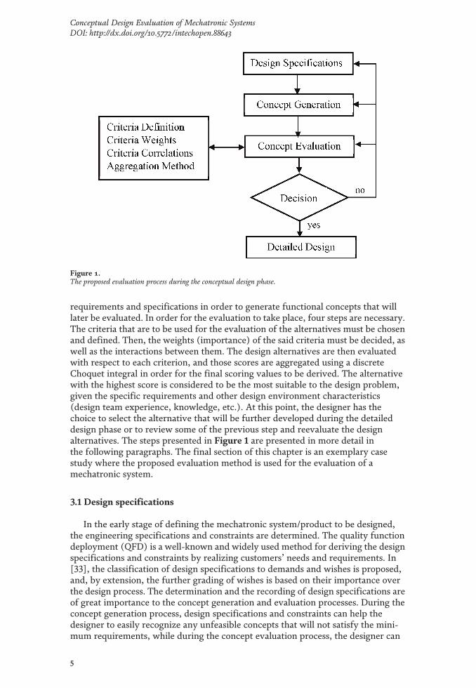
requirements and specifications in order to generate functional concepts that willlater be evaluated. In order for the evaluation to take place, four steps are necessary.The criteria that are to be used for the evaluation of the alternatives must be chosenand defined. Then, the weights (importance) of the said criteria must be decided, aswell as the interactions between them. The design alternatives are then evaluatedwith respect to each criterion, and those scores are aggregated using a discreteChoquet integral in order for the final scoring values to be derived. The alternativewith the highest score is considered to be the most suitable to the design problem,given the specific requirements and other design environment characteristics(design team experience, knowledge, etc.). At this point, the designer has thechoice to select the alternative that will be further developed during the detaileddesign phase or to review some of the previous step and reevaluate the designalternatives. The steps presented in Figure 1 are presented in more detail inthe following paragraphs. The final section of this chapter is an exemplary casestudy where the proposed evaluation method is used for the evaluation of amechatronic system.
3.1 Design specifications
In the early stage of defining the mechatronic system/product to be designed,the engineering specifications and constraints are determined. The quality functiondeployment (QFD) is a well-known and widely used method for deriving the designspecifications and constraints by realizing customers’ needs and requirements. In[33], the classification of design specifications to demands and wishes is proposed,and, by extension, the further grading of wishes is based on their importance overthe design process. The determination and the recording of design specifications areof great importance to the concept generation and evaluation processes. During theconcept generation process, design specifications and constraints can help thedesigner to easily recognize any unfeasible concepts that will not satisfy the mini-mum requirements, while during the concept evaluation process, the designer can
Figure 1.The proposed evaluation process during the conceptual design phase.
5
Conceptual Design Evaluation of Mechatronic SystemsDOI: http://dx.doi.org/10.5772/intechopen.88643

consult the list of customer requirements and design specifications for the evalua-tion criterion selection and the determination of their weights.
3.2 Concept generation
Concept generation is the process where possible solutions to the design problemare realized based on design specifications and functions that the system/productmust accomplish. In order for a generated concept to be considered a feasiblesolution to the design problem, the two following conditions must be satisfied: (a)the concept meets at least the minimum design specifications, and (b) it includesthe necessary software and hardware components [28]. Concepts can berepresented in different ways, such as sketches or flow diagrams, function hierar-chies, textual notes, or table representations. However, regardless of which way aconcept is represented, enough detail must be developed to model performance sothat the functionality of the idea can be ensured [1]. The quality and the thorough-ness of the generated alternatives mainly depend on the available information andknowledge about the design problem at that early stage of the process and theexperience of the design team.
3.3 Concept evaluation
In the concept evaluation stage, the concepts that have been generated are beingevaluated with respect to some criteria. The performance of each alternative withrespect to each criterion is rated, and these scores are aggregated with a specifiedaggregation function. The purpose of the evaluation is to support the decision-making process of the designer and help him/her to choose the best concept forfurther analysis in the detail design stage. In this section, the basic ideas behind eachstep of the process will be described, and different ways of implementing them willbe mentioned. More emphasis will be placed on describing the foundations andmethods (criterion definition, aggregation function, correlations between criteria)to be applied in the exemplary case study that follows in the next section.
3.4 Criterion definition
A criterion can be thought of as a measure of performance for an alternative[34]. As we saw earlier in the state of the art section, more than a few criteria andcombinations of those criteria have been proposed for the evaluation ofmechatronic concepts. The type and number of criteria to be used are up to thedesigner and the stakeholders that take part in the design process. The selection ofcriteria could depend on the designer’s experience and personal judgment; theavailable information and knowledge about the design problem; the alternativesand the abstraction level of their description, design specifications, and customerrequirements; and whether the designer wants to incorporate the interactionsamong the criteria in the decision-making process.
For the purposes of this chapter, the mechatronic abilities proposed byMoulianitis in [28] as criteria for the evaluation of mechatronic systems will be usedin the exemplary case study. The criteria are based on the collective knowledgepresented in the Multi Annual Roadmap (MAR) for Robotics in Europe [29]. Themechatronic abilities found in [28] are the following:
• Adaptability
• Configurability
6
Emerging Trends in Mechatronics

• Decisional autonomy
• Dependability
• Interaction ability
• Motion ability
• Perception ability
Abilities provide a basis for setting performance metrics and for applicationproviders to specify desired levels of system performance [29]. These ability levelsare adapted to mechatronic criteria, and a scoring scale for concept evaluation withrespect to these criteria is presented [28]. Different scaling types for scoring andevaluation of criteria have been proposed, and the dispute concerning the superior-ity among them has been discussed in [35]. The way the criteria are mapped toscoring methods affects the evaluation results, meaning that a suitable mappingcould lead to more realistic results. However, this work is outside the scope of thischapter and is left for future work.
For the scoring of alternatives, it is assumed that the progression of the levelsadvances the characteristics of the system linearly, so a linear interpolation is usedto map each level to a score. The criteria are scaled in the same universe ofdiscourse, with the lowest possible value being equal to zero and the highest possi-ble equal to one. The scores of the intermediate levels are assigned linearly betweenzero and one. In the following, the scaling of the criteria according to [28], as well asshort descriptions of the criteria, is provided.
3.4.1 Adaptability
Fricke [36] defined adaptability as the ability of a system to adapt in order todeliver intended function ability under varying conditions by changing the valuesof the design parameters either actively (online) or passively (off-line). In [29],adaptability is defined as the ability of the system to adapt itself to different workscenarios and different environments and conditions. Adaptability is often mixedwith configurability and decisional autonomy but is differentiated byconfigurability in the sense that adaptation is mostly devoted to the parameterchange rather than to the structure change. The difference between autonomousdecision and adaptation is that adaptation takes place over time based on an accu-mulation of experience, while decisional autonomy is a result of environmentalperception by means of sensors and cognitive mechanisms.
Adaptability can be broken down to five ability levels, starting from Level 0when the system has no ability to adapt and reaching up to Level 4 when the processof adaptation is carried out by multiple agents. In the three intermediate levels, thesystem behavior is self-evaluated, and the need for parameter adaptation is recog-nized (Level 1), and in addition, individual parameters can be altered based on localperformance assessment (Level 3), and in Level 4 the adaptation concerns multipleparameter changes. The levels of adaptability and the scaling for the scoring of eachlevel are presented in Table 1.
3.4.2 Configurability
Configurability is the ability of a system to alter its configuration to performdifferent tasks. As it is stated in [29], configurability must be carefully distinguished
7
Conceptual Design Evaluation of Mechatronic SystemsDOI: http://dx.doi.org/10.5772/intechopen.88643
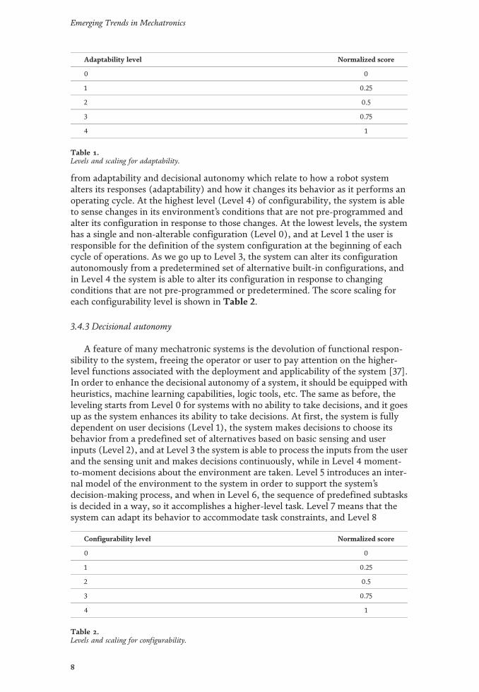
from adaptability and decisional autonomy which relate to how a robot systemalters its responses (adaptability) and how it changes its behavior as it performs anoperating cycle. At the highest level (Level 4) of configurability, the system is ableto sense changes in its environment’s conditions that are not pre-programmed andalter its configuration in response to those changes. At the lowest levels, the systemhas a single and non-alterable configuration (Level 0), and at Level 1 the user isresponsible for the definition of the system configuration at the beginning of eachcycle of operations. As we go up to Level 3, the system can alter its configurationautonomously from a predetermined set of alternative built-in configurations, andin Level 4 the system is able to alter its configuration in response to changingconditions that are not pre-programmed or predetermined. The score scaling foreach configurability level is shown in Table 2.
3.4.3 Decisional autonomy
A feature of many mechatronic systems is the devolution of functional respon-sibility to the system, freeing the operator or user to pay attention on the higher-level functions associated with the deployment and applicability of the system [37].In order to enhance the decisional autonomy of a system, it should be equipped withheuristics, machine learning capabilities, logic tools, etc. The same as before, theleveling starts from Level 0 for systems with no ability to take decisions, and it goesup as the system enhances its ability to take decisions. At first, the system is fullydependent on user decisions (Level 1), the system makes decisions to choose itsbehavior from a predefined set of alternatives based on basic sensing and userinputs (Level 2), and at Level 3 the system is able to process the inputs from the userand the sensing unit and makes decisions continuously, while in Level 4 moment-to-moment decisions about the environment are taken. Level 5 introduces an inter-nal model of the environment to the system in order to support the system’sdecision-making process, and when in Level 6, the sequence of predefined subtasksis decided in a way, so it accomplishes a higher-level task. Level 7 means that thesystem can adapt its behavior to accommodate task constraints, and Level 8
Adaptability level Normalized score
0 0
1 0.25
2 0.5
3 0.75
4 1
Table 1.Levels and scaling for adaptability.
Configurability level Normalized score
0 0
1 0.25
2 0.5
3 0.75
4 1
Table 2.Levels and scaling for configurability.
8
Emerging Trends in Mechatronics

translates to the alteration of the strategy as the system gathers new informationand knowledge about the environment. In the two higher levels, decisions aboutactions are altered within the time frame of dynamic events that occur inside theenvironment (Level 9), and in Level 10, system compensation in real-time events isenabled by the alteration of the tasks themselves. The levels and the correspondingscores are presented in Table 3.
3.4.4 Dependability
Dependability of mechatronic units is defined as the qualitative and quantitativeassessment of the degree of performance, reliability, and safety taking into consid-eration all relevant influencing factors [38]. The higher the level of dependability ofa system, the more reliable this system is. Seven levels of dependability are definedas follows. At Level 0, there is no system ability to predict any failures. At Level 1,dependability is measured only by estimations of the mean time between failures,and the system has no real ability to detect or prevent those failures. At Level 2, thesystem has the ability to diagnose a failure and enter safe mode operation, while atLevel 3 the system is able to diagnose a number of failures and recover from aproportion of them. If the system has the added ability to predict the consequencesto its tasks caused by the diagnosed failures, then it has reached Level 4. At Level 5,the system can communicate its failures to other systems in order to rearrange theaggregate sequence of tasks and keep its mission dependable, and as we reach Level6, the system is able to predict a failure and act to prevent it. Dependability levelsand scores are presented in Table 4.
3.4.5 Interaction ability
It is the ability of a system to interact physically, cognitively, and socially eitherwith users, operators, or other systems around it [29]. In the concept of humanadaptive mechatronics (HAM) [39], the goal is to design a mechatronic system thatincludes the user in the control loop and modifies the functions and the structure ofuser-machine interface to improve the human’s operational skills. Interactivity isconsidered in most of the modern mechatronic systems to facilitate either the
Decisional autonomy level Normalized score
0 0
1 0.1
2 0.2
3 0.3
4 0.4
5 0.5
6 0.6
7 0.7
8 0.8
9 0.9
10 1
Table 3.Levels and scaling for decisional autonomy.
9
Conceptual Design Evaluation of Mechatronic SystemsDOI: http://dx.doi.org/10.5772/intechopen.88643
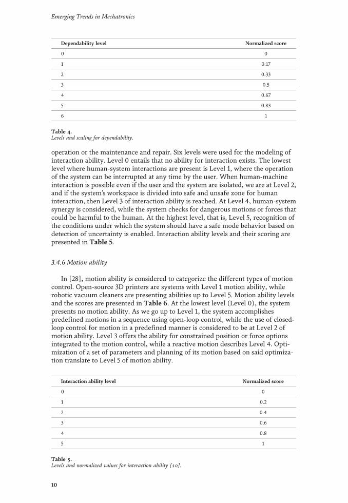
operation or the maintenance and repair. Six levels were used for the modeling ofinteraction ability. Level 0 entails that no ability for interaction exists. The lowestlevel where human-system interactions are present is Level 1, where the operationof the system can be interrupted at any time by the user. When human-machineinteraction is possible even if the user and the system are isolated, we are at Level 2,and if the system’s workspace is divided into safe and unsafe zone for humaninteraction, then Level 3 of interaction ability is reached. At Level 4, human-systemsynergy is considered, while the system checks for dangerous motions or forces thatcould be harmful to the human. At the highest level, that is, Level 5, recognition ofthe conditions under which the system should have a safe mode behavior based ondetection of uncertainty is enabled. Interaction ability levels and their scoring arepresented in Table 5.
3.4.6 Motion ability
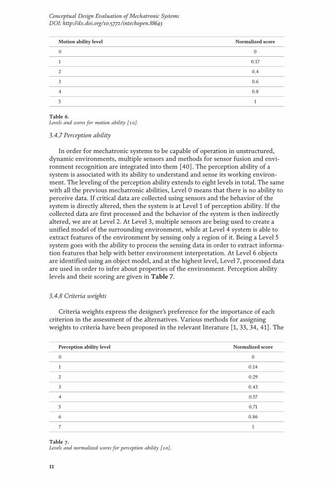
In [28], motion ability is considered to categorize the different types of motioncontrol. Open-source 3D printers are systems with Level 1 motion ability, whilerobotic vacuum cleaners are presenting abilities up to Level 5. Motion ability levelsand the scores are presented in Table 6. At the lowest level (Level 0), the systempresents no motion ability. As we go up to Level 1, the system accomplishespredefined motions in a sequence using open-loop control, while the use of closed-loop control for motion in a predefined manner is considered to be at Level 2 ofmotion ability. Level 3 offers the ability for constrained position or force optionsintegrated to the motion control, while a reactive motion describes Level 4. Opti-mization of a set of parameters and planning of its motion based on said optimiza-tion translate to Level 5 of motion ability.
Dependability level Normalized score
0 0
1 0.17
2 0.33
3 0.5
4 0.67
5 0.83
6 1
Table 4.Levels and scaling for dependability.
Interaction ability level Normalized score
0 0
1 0.2
2 0.4
3 0.6
4 0.8
5 1
Table 5.Levels and normalized values for interaction ability [10].
10
Emerging Trends in Mechatronics
3.4.7 Perception ability
In order for mechatronic systems to be capable of operation in unstructured,dynamic environments, multiple sensors and methods for sensor fusion and envi-ronment recognition are integrated into them [40]. The perception ability of asystem is associated with its ability to understand and sense its working environ-ment. The leveling of the perception ability extends to eight levels in total. The samewith all the previous mechatronic abilities, Level 0 means that there is no ability toperceive data. If critical data are collected using sensors and the behavior of thesystem is directly altered, then the system is at Level 1 of perception ability. If thecollected data are first processed and the behavior of the system is then indirectlyaltered, we are at Level 2. At Level 3, multiple sensors are being used to create aunified model of the surrounding environment, while at Level 4 system is able toextract features of the environment by sensing only a region of it. Being a Level 5system goes with the ability to process the sensing data in order to extract informa-tion features that help with better environment interpretation. At Level 6 objectsare identified using an object model, and at the highest level, Level 7, processed dataare used in order to infer about properties of the environment. Perception abilitylevels and their scoring are given in Table 7.
3.4.8 Criteria weights
Criteria weights express the designer’s preference for the importance of eachcriterion in the assessment of the alternatives. Various methods for assigningweights to criteria have been proposed in the relevant literature [1, 33, 34, 41]. The
Motion ability level Normalized score
0 0
1 0.17
2 0.4
3 0.6
4 0.8
5 1
Table 6.Levels and scores for motion ability [10].
Perception ability level Normalized score
0 0
1 0.14
2 0.29
3 0.43
4 0.57
5 0.71
6 0.86
7 1
Table 7.Levels and normalized scores for perception ability [10].
11
Conceptual Design Evaluation of Mechatronic SystemsDOI: http://dx.doi.org/10.5772/intechopen.88643

most commonly used weight assignment technique for concept evaluation in themechatronic design process is the direct rating of each criterion weight by thedecision-makers (direct rating, point allocation, numerical scale) [1, 41, 42]. Theeigenvector method, proposed by Saaty in [43], is a simple method that usespairwise comparisons and ratings between criteria in order to formulate the weightof each individual criterion. In [34, 41], the reader can find a more in-depth analysisof different weight rating methods and how to choose the most suitable methoddepending on the decision problem. In the process of assigning values to criteriaweights, the design team should make an effort to consider the design specificationsand customer requirements and try to reflect them on the assigned values.
3.5 Criteria correlations and aggregation method
Choquet integral is a nonlinear fuzzy integral, which has been proposed andused for the aggregation of interacting criteria [22]. The integral allows for thedesigner to incorporate interactions into the evaluation process by providingweighting factors (weights) both for the criteria and the correlations between eachsubset of criteria. Considering the set of criteria X ¼ x1; x2;…; xnf g, the concept of afuzzy measure [44] is defined.
A fuzzy measure on the set X of criteria is a set function μ : P Xð Þ ! 0; 1½ �satisfying the following axioms:
i. μ ∅ð Þ ¼ 0 and μ Xð Þ ¼ 1
ii.A⊂B⊂C implies μ Αð Þ≤ μ Βð Þ.
In this context, μ Αð Þ represents the weight of importance of criterion A [22]. Byexpressing the weighting factors of each subset of criteria, the interactions betweencriteria can be taken into account during the aggregation. Four types of interactionsbetween criteria are presented in this chapter. A positive interaction (or correlation)means that a good score in criterion xi implies a good score in criterion xj and viceversa, while a negative correlation between interacting criteria means that a goodscore in criterion xi implies a bad score in criterion xj and vice versa. If a criterion hasa veto effect on the evaluation process, a bad score in criterion xi results in a badglobal score. A pass effect, on the other hand, implies that a good score in criterion xiresults in a good global score. In Table 8, the four types of interactions betweencriteria and the relations between their weighting factors are presented.
Given the set of criteria X and the fuzzy measure μ, the Choquet integral of afunction f : X ! 0; 1½ � with respect to μ is defined by [23]
Cμ ¼ Cμ f x1ð Þ;…; f xnð Þð Þ≔Xn
i¼1
f x ið Þ� �� f x i�1ð Þ
� �� �μ Α ið Þ� �� �
(1)
Interaction Relation
Positive correlation μ xi; xj� �
< μ xið Þ þ μ xj� �
Negative correlation μ xi; xj� �
> μ xið Þ þ μ xj� �
Veto effect μ Tð Þ≈0 if T ⊂X � xif gPass effect μ Tð Þ≈ 1 if T ⊂X, xi ∈T
Table 8.Correlations between criteria.
12
Emerging Trends in Mechatronics

where :ð Þ ið Þ indicates that the indices have been permuted so that 0≤ f x1ð Þ≤…≤ f xnð Þ≤ 1, f x 0ð Þ
� � ¼ 0, and A ið Þ ¼ x ið Þ;…; x nð Þ� �
:
or equally [45]
Cμ ¼Xn
i¼1
f x ið Þ� �
μ Α ið Þ� �� μ Α iþ1ð Þ
� �� �(2)
where :ð Þ ið Þ indicates that the indices have been permuted so that the criteriavalues are sorted in ascending order, such that 0≤ f x1ð Þ≤…≤ f xnð Þ≤ 1,A ið Þ ¼ x ið Þ;…; x nð Þ
� �, and A nþ1ð Þ ¼ 0.
Marichal [45] also proposed an axiomatic characterization of the integral tomotivate its use in applications. The expression he ended up with is the Choquetintegral in terms of the Mobius representation:
Cμ ¼X
i∈N
a ið Þ ∙ f x ið Þ� �þ
X
i;jf g⊆Na i; jð Þ ∙ f x ið Þ
� �∧ f x jð Þ
� �� �þ… (3)
where a ið Þ ¼ μ ið Þ and a i; jð Þ ¼ μ i; jð Þ � μ ið Þ þ μ jð Þ½ �.
4. Case study: automated BMP system
The proposed method is used for the concept evaluation of an automatedbiomethane potential (BMP) measurement system. Before the presentation of theevaluation of the system, it should be mentioned that all the scoring values ofalternatives, the criteria weights, and the criteria correlation weights were givenintuitively by the authors of this chapter. This is not ideal, since the design teamshould strive for a more analytic and objective approach to the evaluation process.However, the study of the cognitive mechanisms that take place during the evalua-tion and the consideration of different ways of scoring criteria and criteria weightsis left for future work. The purpose of this chapter is to focus more on the generalmethodology for concept evaluation and not so on its specifics.
Production of biogas from different organic materials is an interesting source ofrenewable energy. The biomethane potential (BMP) of these materials has to bedetermined to get insight in design parameters for anaerobic digesters [46]. The testis conducted by placing an active inoculum and a sample of a substrate in a sealedcontainer vessel and measuring the amount of the gas produced [47]. The basicsteps followed in a BMP test are:
1.The substrate and the inoculum are placed in the sealed reactor vessel.
2.Stirring (not continuous) and heating (the temperature is held constant in therange 20–90°C, depending on the test mixture) of the test mixture to enhancebiogas production. The production of biogas starts at this step and continuousuntil the end of the experiment.
3.Absorption of CO2. The biogas is transferred to a reactor vessel containing(liquid) NaOH. This allows for the dissolution of the CO2 in the NaOHsolution, and the remaining gas volume is representative of the CH4 present inthe biogas.
13
Conceptual Design Evaluation of Mechatronic SystemsDOI: http://dx.doi.org/10.5772/intechopen.88643

4.Gas flow measurement. The CH4 is transferred to the flow measurementsystem. The volume of gas produced in a specific time interval is quantified,usually under the fluid displacement principle.
5.Data analysis and reporting.
An average BMP test can last for more than 30 days, during which the test systemmust run without disruptions. The BMP test can be done manually, where humaninterference in 24-h intervals is needed in order for the gas flow measurement to takeplace. The whole process can also be automated, where no human interaction isneeded for the gas flow measurement, and the analysis and representation of theresults take place in real time during the experimental process. Two commercialproducts that automate the BMP test are the AMPTS II by Bioprocess Control Sys-tems [48] and the Biogas Batch Fermentation System by Ritter [49]. The followingscheme represents the basic functions that need to be accomplished for the automa-tion of the process. The functions presented in the scheme in Figure 2 are incorpo-rated in both products (AMPTS II and Biogas Batch Fermentation System).
In Figures 3 and 4, the two products are presented in relation to the schemegiven in Figure 2. They accomplish the same functions but with slightly differentcomponents and working principles.
Figure 2.Subfunctions and flows of material and energy of an automated BMP system.
Figure 3.The AMPTS II system by bioprocess control [48].
14
Emerging Trends in Mechatronics

The agitation in the case of the AMPTS is accomplished with an overhead stirrerwith a special airtight cap that allows for the stirring of the mixture with a stirringrod coupled to the actuator. Ritter used an overhead stirrer, but the couplingbetween the actuator and the stirring rod is accomplished with a magnetic coupling.Ritter utilized a heating oven for the temperature control of the mixture, while inAMPTS II a water bath is used. For the ultralow gas flow measurement (ULGFM),Bioprocess Control uses their patented gas flow cell meter which operates based onthe liquid displacement and buoyancy working principles, as well as the Hall effect.Ritter’s gas flowmeter is based on the same operating principles but utilizes thetipping bucket effect in combination with a Hall effect sensor. For the normaliza-tion of the measurement results, a temperature and a barometric pressure sensor arebeing used. The user can control the speed and the movement direction of theactuator motors through the software.
The main requirements considered by the design team are that the system canreliably operate for the whole duration of the experiment (more than 30 days), thetemperature of the mixture inside the reactor vessel is held constant at aprespecified temperature, it offers an automated and accurate flow measurementmethod, its components and subsystems are gastight in order for the gas to be ableto travel through the system without any leakages, and finally the results arepresented to the user via a software UI.
After the listing of the design requirements, the design team proceeds with thegeneration of alternative concepts. For the facilitation of concept generation, thesystem could be modeled in various ways, such as the scheme shown in Figure 5. InTable 9, the information about the mechatronic system is presented in terms ofenergy, material, and information flows [1].
By studying existing automated BMP systems, the design team attempted tomodel the basic functions of any automated BMP measuring system as a flowchart.This flowchart representation of the system functions is meant to be representativeof any automated BMP measurement system and help the design team with thebetter understanding of the system to be designed.
In [28], a design tree with the subfunctions of a mechatronic object, morespecifically an educational firefighting robot, is presented. A representation of theautomated BMP system in a manner similar to that design tree is presented inFigure 5.
Figure 4.The biogas batch fermentation system by Ritter [49].
15
Conceptual Design Evaluation of Mechatronic SystemsDOI: http://dx.doi.org/10.5772/intechopen.88643

The component and component categories that are considered in the design treein Figure 5 are the following:
• Sensing: For temperature control inside the reactor vessel, pressure recordingand gas measurement.
• Information processing: Software that is responsible for the actuator andtemperature control, the data logging and processing of flow measurementvalues, and the calculation and representation of the experimental results.
• Power components: The power supply of the actuators, the heating elements,and the control and software electronics.
• Work components: The components that produce some kind of work.Mechanical work by the agitation actuators and thermal work by the heatingelements.
• Mechanical components: For the casing and structural support of the system,the tubing connections, the vessels (reactor vessel, absorption unit), the stirrer,the airtight components, and the mechanical parts contained within the flowmeasurement sensor.
• Ultralow gas flow measurement: Working principles incorporated within thegas flow measurement system. In reality, the design of an ultralow gas flowmeasurement system could be considered by itself as a distinct mechatronicdesign problem.
Energy flow Material flow Information flow
Transformation of electrical power tokinetic energy (agitation)
Flow of gas mixturesthrough the system
Temperature, pressure, and flowsensing
Transformation of electrical power tothermal energy
Agitation of mixture inthe reactor vessels
Control of actuators
Control of heating element
Flow sensor data processing andresult representation
Table 9.Energy, material, and information flow representation of the automated BMP system.
Figure 5.Design tree for automated BMP measurement system.
16
Emerging Trends in Mechatronics

• Communication: For the inter process communications between the softwareand the rest subsystems (actuators, heater, sensors).
Based on the classification of components considered in the design tree of thesystem (Figure 5) and the subsystems considered in the flowchart representation ofthe system (Figure 2), the design team came up with a first set of alternativeconcepts for the automated BMP system. The alternative components consideredare presented in Table 10.
As it can be seen in Table 10, not all subsystems and components were takeninto account in the generation of possible solutions, but this does not mean that thebasic requirements of the system are not met by the alternatives that have beenchosen. As mentioned in previous sections, the quality and completeness of thesolutions depend to a large extent on the available information and knowledgeabout the design object and the design team experience. It should also be borne inmind that the evaluation of the solutions is an iterative process, the purpose ofwhich is to support the design team in the decision-making processes during theconceptual design phase.
Based on the data of Table 11, there are 4� 3� 24 ¼ 192 possible design solu-tions. The study of the procedures for reducing the number of solutions lies outsidethe scope of this chapter and is left for future work. However, some of the factorsthat may play an important role in rejecting some alternatives without requiring athorough evaluation process are outlined. The factors are as follows.
• The design team is not familiar with relevant technology [28].
• The assembly/communication between some components is unacceptablycomplicated or even impossible.
• The cost of some alternatives is too high.
• Some alternatives have already been realized by competitors, and they are notconsidered innovative enough.
• The alternative does not satisfy the basic system/product requirements.
• The time frame for the design process does not allow for the exhaustiveevaluation of the alternatives, and a decision must be made quickly.
Agitation system Heatingsystem
Temperaturesensors
Ultralow gas flowmeasurement(ULGFM)
Communication
1. Actuator: stepper,DC brushed/brushless, servo2. Stirrer: overheadcoupled stirrer,magnetic stirrer
3. Waterbathheater4.Heatingoven5. Siliconjacketheater
6. Resistancethermometerdetector (RTD)7. Thermocouple
8. Liquiddisplacement andbuoyancy and Hallsensor9. Liquiddisplacement andoptical sensor
10. Direct, wiredbetween software andsubsystems11. Radio frequency(Wi-Fi) betweensoftware and subsystems
Table 10.Automated BMP measurement system alternatives based on system subfunctions.
17
Conceptual Design Evaluation of Mechatronic SystemsDOI: http://dx.doi.org/10.5772/intechopen.88643

In the same manner, if an alternative presents really low cost and complexityand the design team is very familiar with the relevant technology, it could be chosenfor further development along with the alternatives that will be chosen after theevaluation process. The design team came up with the three design alternativesDAk k ¼ 1, 2, 3ð ) presented in Table 11.
Each design alternative uses a different type of actuator for the stirring of themixture. In DA1 and DA2, a brushed DC motor and a brushless DC motor, respec-tively, are used. A stepper motor with the additional components for the open-loopcontrol of the system is being utilized in DA3. As for the other agitation compo-nents, DA1 and DA2 are using an overhead stirrer which is coupled with the motorwith a linear coupling, e.g., helix coupler, while the third alternative makes use of amagnetic coupling between the actuator and the stirrer. The three design alterna-tives realize the heating of the mixture inside the reaction vessels in three differentways. The two first alternatives, i.e., DA1 and DA2, use a water bath and a heatingoven, respectively, for the heating of the mixture, while in DA3 a silicon rubberheater (etch foil heater) is chosen for the heating purposes. Thermocouples (DA1)and a RTD sensor (DA2, DA3) are chosen as alternative solutions for temperaturesensing inside the reactor vessel. The two alternatives that the design team came upwith for the realization of the ultralow gas flow measurement system are presentedin Figure 6.
The first alternative for the ULGFMS, presented in Figure 6a and used in designalternatives DA1 and DA3, utilizes the liquid displacement discipline and with theuse of an optical sensor is able to calculate the flow of the produced gas. As gas
Designalternatives
DA1 DA2 DA3
Actuator DC brushed DC brushless Stepper
Stirrer Overhead with linearcoupling
Overhead with linear coupling Magnetic
Heating Water bath Heating oven Silicon jacket
Temperaturesensors
Thermocouple RTD RTD
ULGFM Liquid displacementand optical sensor
Liquid displacement andbuoyancy and Hall sensor
Liquid displacementand optical sensor
Communication Wired connections Wired connections Radio frequencies(Wi-Fi)
Table 11.Three design alternatives selected for evaluation by the design team.
Figure 6.Ultralow flow measurement alternatives. (a) The liquid displacement discipline. (b) The tipping bucketmechanism.
18
Emerging Trends in Mechatronics
enters the chamber, pressure arises, and the liquid level inside the chamber risesuntil it reaches the point where the optical sensor is pointed at. The sensor recordsthe phenomenon, and the gas is then released from the system, the liquid leveldrops again, and the process repeats itself. By calibrating the system so that weknow the exact gas volume needed for the liquid to reach the optical sensor’s leveland recording the number of times it reaches that level in a given time interval, wecan estimate the gas flow. The second alternative presented in Figure 6b andutilized in design alternative DA2 makes use of a tipping bucket mechanism. Abucket-like chamber is placed inside a container packed with a liquid. Gas bubblesenter the bucket, and when enough of them have gathered, the bucket tips becauseof the buoyancy. During the tipping motion, a Hall sensor records the phenomenon,and the gas is released. As we can see, the second alternative is very similar to thefirst one. Finally, for the first two alternatives DA1 and DA2, the communicationbetween its subsystems will all be achieved via physical (wired) communicationprotocols and hardware components, while the third DA3 alternative is using radiofrequencies, namely, Wi-Fi communication between its subsystems.
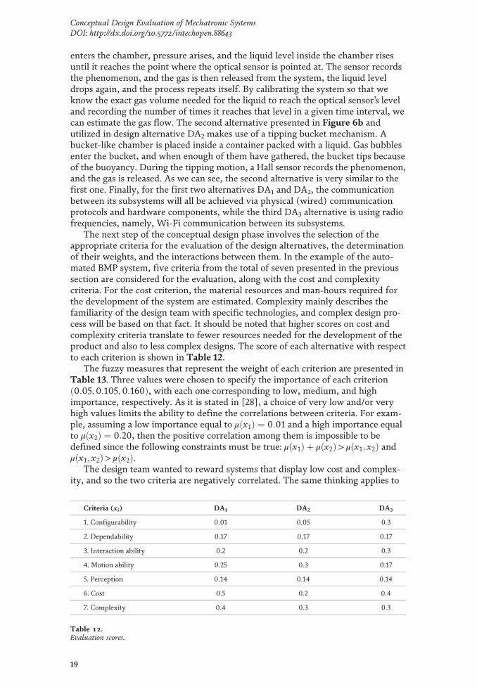
The next step of the conceptual design phase involves the selection of theappropriate criteria for the evaluation of the design alternatives, the determinationof their weights, and the interactions between them. In the example of the auto-mated BMP system, five criteria from the total of seven presented in the previoussection are considered for the evaluation, along with the cost and complexitycriteria. For the cost criterion, the material resources and man-hours required forthe development of the system are estimated. Complexity mainly describes thefamiliarity of the design team with specific technologies, and complex design pro-cess will be based on that fact. It should be noted that higher scores on cost andcomplexity criteria translate to fewer resources needed for the development of theproduct and also to less complex designs. The score of each alternative with respectto each criterion is shown in Table 12.
The fuzzy measures that represent the weight of each criterion are presented inTable 13. Three values were chosen to specify the importance of each criterion0:05;0:105;0:160ð Þ, with each one corresponding to low, medium, and highimportance, respectively. As it is stated in [28], a choice of very low and/or veryhigh values limits the ability to define the correlations between criteria. For exam-ple, assuming a low importance equal to μ x1ð Þ ¼ 0:01 and a high importance equalto μ x2ð Þ ¼ 0:20, then the positive correlation among them is impossible to bedefined since the following constraints must be true: μ x1ð Þ þ μ x2ð Þ> μ x1; x2ð Þ andμ x1; x2ð Þ> μ x2ð Þ.
The design team wanted to reward systems that display low cost and complex-ity, and so the two criteria are negatively correlated. The same thinking applies to
Criteria (xi) DA1 DA2 DA3
1. Configurability 0.01 0.05 0.3
2. Dependability 0.17 0.17 0.17
3. Interaction ability 0.2 0.2 0.3
4. Motion ability 0.25 0.3 0.17
5. Perception 0.14 0.14 0.14
6. Cost 0.5 0.2 0.4
7. Complexity 0.4 0.3 0.3
Table 12.Evaluation scores.
19
Conceptual Design Evaluation of Mechatronic SystemsDOI: http://dx.doi.org/10.5772/intechopen.88643

two other negative correlations between complexity/configurability and cost/configurability. A system with great configurability allows for the user to customizethe BMP system easier and faster, which translates to higher interaction abilitylevels, and thus, the two criteria are positively correlated. All interactions and thecorresponding weights are presented in Table 14.
The final evaluation scores of each alternative are presented in Table 15. Theevaluation scores are the Choquet integral values that were calculated based onEq. (3). Alternative DA3 scored the highest score, while DA1 and DA2 came upsecond and third, respectively, as it is shown below. DA1 and DA3 present similarperformance characteristics, with DA1 having a marginal lead in cost and complex-ity performance but falls short on configurability performance.
5. Conclusions
In this chapter, some well-known methods for the conceptual analysis andevaluation during the mechatronic design process are discussed, and a method forthe evaluation of generated design alternatives is proposed. The proposed designcriteria, which were derived from the multi annual roadmap in robotics in Europe,were presented in [28]. Four interactions between criteria are presented and theChoquet integral along with the two additive fuzzy measures used for dealing withthe aggregation of the evaluation scores.
Criteria (xi) Weight (μ xið Þ)1. Configurability μ x1ð Þ ¼ 0:16
2. Dependability μ x2ð Þ ¼ 0:05
3. Interaction ability μ x3ð Þ ¼ 0:105
4. Motion ability μ x4ð Þ ¼ 0:05
5. Perception μ x5ð Þ ¼ 0:05
6. Cost μ x6ð Þ ¼ 0:16
7. Complexity μ x7ð Þ ¼ 0:16
Table 13.Criteria weights.
Criteria xi; xj� �
Interaction Set weight μ xi; xj� �Þ�
Cost/complexity Negative μ x6; x7ð Þ ¼ 0:45
Complexity/configurability Negative μ x1; x7ð Þ ¼ 0:40
Interaction ability/configurability Positive μ x1; x3ð Þ ¼ 0:20
Cost/configurability Negative μ x1; x6ð Þ ¼ 0:35
Table 14.Criteria correlations and set weights.
Design alternatives DA1 DA2 DA3
Evaluation scores 0.2995 0.1960 0.3205
Table 15.Choquet values of the alternative scores.
20
Emerging Trends in Mechatronics

The most useful outcomes of this chapter are as follows. (i) The modeling of thesystem can lead to a better understanding of the problem and make the evaluationprocess easier and more accurate. (ii) The proposed mechatronic abilities can beutilized in a number of different situations. However, the score scaling of thecriteria needs to be further investigated. (iii) The proposed method is there tosupport the design team on the selection of the most suitable design alternative. Theevaluation process and the results obtained from it are dependent on the experienceof the design team, the number of people participating in the evaluation, and theavailable knowledge at the time the decision is made.
Acknowledgements
This research has been co-financed by the European Union and Greek nationalfunds through the Operational Programme for Competitiveness, Entrepreneurshipand Innovation, under the call RESEARCH-CREATE-INNOVATE (project code:T1EDK-03148).
Author details
Eleftherios Katrantzis1*, Vassilis C. Moulianitis1 and Kanstantsin Miatliuk2
1 Department of Product and Systems Design Engineering, University of theAegean, Ermoupoli, Syros, Greece
2 Department of Automatic Control and Robotics, Bialystok University ofTechnology, Bialystok, Poland
*Address all correspondence to: [email protected]
© 2020TheAuthor(s). Licensee IntechOpen.Distributed under the terms of theCreativeCommonsAttribution -NonCommercial 4.0 License (https://creativecommons.org/licenses/by-nc/4.0/),which permits use, distribution and reproduction fornon-commercial purposes, provided the original is properly cited. –NC
21
Conceptual Design Evaluation of Mechatronic SystemsDOI: http://dx.doi.org/10.5772/intechopen.88643

References
[1] Ullman D. The Mechanical DesignProcess. 1992
[2] Moulianitis VC, Aspragathos NA,Dentsoras AJ. A model for conceptevaluation in design—An application tomechatronics design of robot grippers.Mechatronics. 2004;14(6):599-622
[3] Shigley JE, Mischke CR. MechanicalDesign Engineering Handbook. Elsevier;2013
[4] Johnson J. Designing with the Mindin Mind Well-Known User InterfaceDesign Rules; 2012
[5] Hudspeth M. Conceptual design inproduct data management. Des. Eng.Technol. News Deskt. Engineering.
[6] French MJ. Conceptual Design forEngineers. London: Springer London;2013
[7] FLH. Project Development andDesign Manual. US Department ofTransportation; 2014 [online].Available from: https://flh.fhwa.dot.gov/resources/
[8] Bryant CR, Stone RB, McAdams DA.Automated Concept Generation fromthe Functional Basis of Design. 2001;573:1-24. Available from: search.informit.com.au
[9] Gero JS, Kannengiesser U. Afunction-behavior-structure ontology ofprocesses, in artificial intelligence forengineering design. Analysis andManufacturing: AIEDAM. 2007;21(4):379-391
[10] Borgo S, Carrara M, Garbacz P,Vermaas PE. A formal ontologicalperspective on the behaviors andfunctions of technical artifacts. ArtificialIntelligence for Engineering Design,Analysis and Manufacturing. 2009;23(1):3-21
[11] Gu CC, Hu J, Peng YH, Li S. FCBSmodel for functional knowledgerepresentation in conceptual design.Journal of Engineering Design. Aug.2012;23(8):577-596
[12] Ralph P, Wand Y. A proposal fora formal definition of the designconcept. Lecture Notes in BusinessInformation Processing (LNBIP). 2009;14:103-136
[13] Hehenberger P, Poltschak F,Zeman K, Amrhein W. Hierarchicaldesign models in the mechatronicproduct development process ofsynchronous machines. Mechatronics.Dec. 2010;20(8):864-875
[14] Sobieszczanski-Sobieski J, Morris A,van Tooren MJL. MultidisciplinaryDesign Optimization Supported byKnowledge Based Engineering. 2015
[15] Koopialipoor M, Fallah A,Armaghani DJ, Azizi A, Mohamad ET.Three hybrid intelligent models inestimating flyrock distance resultingfrom blasting. EngineeringComputations. Jan. 2019;35(1):243-256
[16] Azizi A, P. Y.-C.-B. A. of the S. S. Of,and U. Mechanical Structures:Mathematical Modeling, Springer; 2019K
[17] Azizi A, Ghafoorpoor Yazdi P,Hashemipour M. Interactive design ofstorage unit utilizing virtual reality andergonomic framework for productionoptimization in manufacturing industry.International Journal on InteractiveDesign and Manufacturing. Mar. 2019;13(1):373-381
[18] Miatliuk K. Conceptual Design ofMechatronic Systems. 2017
[19] De Silva CW, Behbahani S. A designparadigm for mechatronic systems.Mechatronics. 2013;23(8):960-966
22
Emerging Trends in Mechatronics

[20] Behbahani S, de Silva CW. System-based and concurrent design of a smartmechatronic system using the conceptof mechatronic design quotient (MDQ).IEEE/ASME Transactions onMechatronics. 2008;13(1):14-21
[21] Behbahani S, de Silva CW.Mechatronic design quotient as the basisof a new multicriteria mechatronicdesign methodology. IEEE/ASMETransactions on Mechatronics. Apr.2007;12(2):227-232
[22] Grabisch M. The application offuzzy integrals in multicriteria decisionmaking. European Journal ofOperational Research. 1996;89(3):445-456
[23] Mohebbi A, Achiche S, Baron L.Mechatronic multicriteria profile(MMP) for conceptual design of arobotic visual servoing system. In:Volume 3: Engineering Systems; HeatTransfer and Thermal Engineering;Materials and Tribology; Mechatronics;Robotics, 2014. p. V003T15A015
[24] Mohebbi A, Achiche S, Baron L.Multi-criteria fuzzy decision support forconceptual evaluation in design ofmechatronic systems: A quadrotordesign case study. Research inEngineering Design. Jul. 2018;29(3):329-349
[25] Moulianitis VC, Aspragathos NA.Design evaluation with mechatronicsindex using the discrete choquetintegral. IFAC Proceedings. Jan. 2010;39(16):348-353
[26] Ferreira IML, Gil PJS. Applicationand performance analysis of neuralnetworks for decision support inconceptual design. Expert Systems withApplications. 2012;39(9):7701-7708
[27] Hammadi M, Choley JY, Penas O,Riviere A, Louati J, Haddar M. A newmulti-criteria indicator for mechatronicsystem performance evaluation in
preliminary design level. In: 2012 9thFrance-Japan & 7th Europe-AsiaCongress on Mechatronics(MECATRONICS)/13th InternationalWorkshop on Research and Educationin Mechatronics (REM). 2012.pp. 409-416
[28] Moulianitis VC, Zachiotis G-AD,Aspragathos NA. A new index based onmechatronics abilities for the conceptualdesign evaluation. Mechatronics. Feb.2018;49:67-76
[29] SPARC. Robotics 2020 Multi-Annual Roadmap MAR ICT-24 ii; 2015
[30] Chen R, Liu Y, Fan H, Zhao J, Ye X.An integrated approach for automatedphysical architecture generation andmulti-criteria evaluation for complexproduct design. Journal of EngineeringDesign. Mar. 2019;30(2–3):63-101
[31] Qi J, Hu J, Peng Y-H. An integratedprinciple solution synthesis method inmulti-disciplinary mechatronic productconceptual design. ConcurrentEngineering. 2018;26(4):341-354
[32] Chami M, Bruel JM. Towards anintegrated conceptual design evaluationof mechatronic systems: The SysDICEapproach. Procedia Computer Science.2015;51(1):650-659
[33] Pahl G, Beitz W. EngineeringDesign: A Systematic Approach; 2013
[34] Sen P, Yang J-B. Multiple CriteriaDecision Support in EngineeringDesign; 2011
[35] Ishizaka A, Labib A. Review of themain developments in the analytichierarchy process. Expert Systems withApplications. 2011;38(11):14336-14345
[36] Fricke E, Schulz AP. Design forchangeability (DfC): Principles toenable changes in systems throughouttheir entire lifecycle. SystemsEngineering. 2005;8(4):342-359
23
Conceptual Design Evaluation of Mechatronic SystemsDOI: http://dx.doi.org/10.5772/intechopen.88643

[37] Bradley D. Mechatronics andintelligent systems. 2005. pp. 395-400
[38] Kochs H-D, Petersen J. AFramework for DependabilityEvaluation of Mechatronic Units; 2004
[39] Yu H. Overview of human adaptivemechatronics. Mathematics andComputers in Business and Economics.2008:152-157
[40] Luo RC, Chou YC, Chen O.Multisensor fusion and integration:Algorithms, applications, and futureresearch directions. In: Proceedings ofthe 2007 IEEE International Conferenceon Mechatronics and Automation,ICMA. Vol. 2007. 2007. pp. 1986-1991
[41] Hwang C-L, Yoon K. Methods forMultiple Attribute Decision Making.Berlin, Heidelberg: Springer; 2012.pp. 58-191
[42] Bottomley PA, Doyle JR, Green RH.Testing the reliability of weightelicitation methods: Direct rating versuspoint allocation. Journal of MarketingResearch. 2003;37(4):508-513
[43] Saaty TL. A scaling method forpriorities in hierarchical structures.Journal of Mathematical Psychology.1986;13:65-75
[44] Sugeno M. Theory of FuzzyIntegrals and its Application. 1972
[45] Marichal J-L. An axiomaticapproach of the discrete Choquetintegral as a tool to aggregate interactingcriteria. IEEE Transactions on FuzzySystems. 2000;8(6)
[46] Holliger C et al. Towards astandardization of biomethane potentialtests. Water Science and Technology.2016;74(11):2515-2522
[47] Angelidaki I et al. Defining thebiomethane potential (BMP) of solidorganic wastes and energy crops: A
proposed protocol for batch assays.Water Science and Technology. Mar.2009;59(5):927-934
[48] Bioprocess Control. AMPTS II—Methane potential analysis tool[Online]. Available from: https://www.bioprocesscontrol.com/products/ampts-ii/ [Accessed: 01-Jun-2019]
[49] Ritter. Biogas Batch FermentationSystem [Online]. Available from:https://www.ritter.de/en/products/biogas-batch-fermentation-system/[Accessed: 01-Jun-2019]
24
Emerging Trends in Mechatronics