chapter a8. bottom-material samples - usgs · pdf fileu.s. geological survey twri book 9...
TRANSCRIPT

U.S. Geological Survey TWRI Book 9 Chapter A8. (Version 1.1, 6/2005)
Techniques of Water-Resources Investigations
Book 9 Handbooks for Water-Resources Investigations
National Field Manual for the Collection of Water-Quality Data
Chapter A8.BOTTOM-MATERIAL
SAMPLES
ByDean B. Radtke

Chapter A8. (Version 1.1, 6/2005) U.S. Geological Survey TWRI Book 9
U.S. DEPARTMENT OF THE INTERIOR GALE A. NORTON, Secretary
U.S. GEOLOGICAL SURVEY P. PATRICK LEAHY, Acting Director
Any use of trade, product, or firm names is for descriptive purposes only and does not imply endorsement by the U.S. Government.
For additional information write to: Chief, Office of Water Quality U.S. Geological Survey 12201 Sunrise Valley Drive Mail Stop 412 Reston, VA 20192 This report is accessible online at http://pubs.water.usgs.gov/twri9A/
U.S. Geological Survey TWRI Book 9 Chapter A8. (Version 1.1, 6/2005)
ForewordThe mission of the Water Resources Discipline of the U.S. Geological Survey (USGS) is to provide the information and understanding needed for wise management of the Nation’s water resources. Inherent in this mission is the responsibility to collect data that accurately describe the physical, chemical, and biological attributes of water systems. These data are used for environmental and resource assessments by the USGS, other government agencies and scientific organizations, and the general public. Reliable and quality-assured data are essential to the credibility and impartiality of the water-resources appraisals carried out by the USGS.
The development and use of a National Field Manual is necessary to achieve consistency in the scientific methods and procedures used, to document those methods and procedures, and to maintain technical expertise. USGS field personnel use this manual to ensure that the data collected are of the quality required to fulfill our mission.
(signed)
Robert M. Hirsch Associate Director for Water

Chapter A8. (Version 1.1, 6/2005) U.S. Geological Survey TWRI Book 9
Techniques of Water-Resources Investigations
Page intentially left blank.s

Bottom-Material Samples (Version 1.1, 6/2005) Contents
BOTTOM-MATERIAL SAMPLES—1
National Field Manual for the Collection of Water-Quality Data
Chapter A8Page
Abstract .................................................................................................. 3
Introduction ........................................................................................... 3
Purpose and scope ............................................................................ 4
Field manual review and revision.................................................... 5
Acknowledgments............................................................................. 5
A8. Bottom-material samples................................................................ 7
8.1 Field trip preparations ............................................................... 9
8.2 Site selection................................................................................ 11
8.2.1 Location of sampling sites ............................................... 11
8.2.2 Number of sampling sites................................................ 13
8.3 Sampling equipment................................................................... 17
8.3.1 Equipment selection ....................................................... 17
8.3.1.A Samplers ........................................................... 18
8.3.1.B Sieves................................................................. 19
8.3.2 Decontamination.............................................................. 23
BOTTOM-MATERIAL SAMPLES

U.S. Geological Survey TWRI Book 9 Chapter A8. (Version 1.1, 6/2005)
2—BOTTOM-MATERIAL SAMPLES
8.4 Sample collection ....................................................................... 25
8.4.1 Sampling procedures ...................................................... 26
8.4.2 Quality-control procedures and requirements ............................................................... 32
8.4.2.A Split samples..................................................... 32
8.4.2.B Concurrent replicate samples.......................... 33
8.5 Sample processing....................................................................... 35
8.5.1 Compositing and subsampling........................................ 36
8.5.2 Sieving and sample handling .......................................... 38
8.6 Sample packaging and shipping ................................................ 41
8.6.1 Sample identification and packaging ............................. 41
8.6.2 Shipping containers and sample shipment..................... 44
8.6.3 Analytical services request form .................................... 45
8.7 Checklist of field equipment and supplies ................................ 47
Conversion factors and abbreviations ...............................................CF–1
Selected references and technical memorandums .........................REF–1
Tables
8-1. Applications and limitations of selected statistical methods for selection of sites for collection of bottom-material samples............................................................. 13
8-2. General characteristics of selected grab and core samplers ............................................................................... 20
8-3. Criteria and considerations for collecting a representative sample of bottom material ................................. 26
8-4. Procedures for selecting sampling locations using selected nonstatistical and statistical methods ........................................................................................ 28
8-5. Checklist of field equipment and supplies ................................. 48

Bottom-Material Samples (Version 1.1, 6/2005) Introduction
BOTTOM-MATERIAL SAMPLES—3
By Dean B. Radtke
ABSTRACTThe National Field Manual for the Collection of Water-Quality Data(National Field Manual) describes protocols (requirements and recommendations) and provides guidelines for U.S. Geological Survey (USGS) personnel who collect data used to assess the quality of the Nation’s surface-water and ground-water resources. This release of Chapter A8 provides guidelines for the equipment and procedures needed to collect and process samples of bottom material for the evaluation of surface-water quality.
Each chapter of the National Field Manual is published separately and revised periodically. Newly published and revised chapters are posted on the World Wide Web on the USGS page "National Field Manual for the Collection of Water-Quality Data." The URL for this page is http://pubs.water.usgs.gov/twri9A/ (accessed April 2005).
INTRODUCTIONAs part of its mission, the U.S. Geological Survey (USGS) collects data needed to assess the quality of our Nation’s water resources. The National Field Manual for the Collection of Water-Quality Data (Na-tional Field Manual) describes protocols (requirements and recom-mendations) and provides guidelines for USGS personnel who collect data used to assess the quality of the Nation’s surface-water and ground-water resources.
Chapter A8.BOTTOM-MATERIAL
SAMPLES

U.S. Geological Survey TWRI Book 9 Chapter A8. (Version 1.1, 6/2005)
4—BOTTOM-MATERIAL SAMPLES
The National Field Manual is Section A of Book 9 of the USGS pub-lication series Techniques of Water-Resources Investigations (TWRI). The National Field Manual is comprised of individually published chapters. Chapter numbers are preceded by an “A” to indi-cate that the report is part of the National Field Manual.
Chapter A8 on bottom-material samples includes procedures and guidelines for selection of sampling sites, selection and decontamina-tion of equipment, and the collection, processing, packaging, and shipping of samples. Formal training and field apprenticeship are nec-essary in order to implement correctly the procedures described in this report.
PURPOSE AND SCOPE
Chapter A8 of the National Field Manual provides guidelines and standard procedures to be used by USGS personnel for field activities related to the collection and processing of bottom-material samples. The National Field Manual is targeted specifically toward field per-sonnel in order to (1) establish and communicate scientifically sound methods and procedures; (2) provide citable documentation for USGS water-quality data-collection protocols; (3) encourage consistent use of field methods for the purpose of producing nationally comparable data; and (4) provide methods that minimize biasing the data and, when properly applied, that result in data that are reproducible within defined limits of variability.
It is impractical to provide guidance that would encompass the entire spectrum of data-collection objectives, site characteristics, environ-mental conditions, and technological advances related to water-qual-ity studies. The fundamental responsibility of field personnel is to select methods that are compatible with the scientific objective for the field work and to use procedures that are consistent with USGS stan-dard procedures to the extent possible. Under some circumstances, data collectors may have to modify standard procedures. However, whenever a standard procedure is modified or an alternative proce-dure is used, a description of the procedure used and supporting qual-ity-assurance information are to be reported with the data.
Bottom-Material Samples (Version 1.1, 6/2005) Introduction
BOTTOM-MATERIAL SAMPLES—5
FIELD MANUAL REVIEW AND REVISION
Chapters of the National Field Manual will be reviewed, revised, and reissued periodically to correct any errors, incorporate technical ad-vances, and address additional topics. Please send comments or cor-rections to: NFM-QW, USGS, 412 National Center, Reston, VA 20192 (or send electronic mail to: [email protected]). Newly pub-lished and revised chapters are posted on the World Wide Web under “National Field Manual for the Collection of Water-Quality Data.” The URL for this page is http://pubs.water.usgs.gov/twri9A/ (accessed April 2005).
ACKNOWLEDGMENTS
The information included in this chapter of the National Field Manualis based on existing manuals, a variety of reference documents, and a broad spectrum of colleague expertise. In addition to the references provided, important source materials include unpublished USGS training and field manuals. The author wishes to acknowledge the fol-lowing individuals in the USGS who developed the field and training manuals that provided the foundation for bottom-material sampling for this National Field Manual: P.D. Capel, D. Childers, Jr., M.E. Dorsey, T.K. Edwards, W.B. Garrett, W.J. Gibbons, L.R. Kister, J.M. Knott, J. Rawson, L.R. Shelton, M.A. Sylvester, and F.C. Wells.
USGS colleagues C.J.O. Childress, C.R. Demas, G.J. Fuhrer, A.J. Horowitz, S.K. Sorenson, P.C. Van Metre, and F.C. Wells provided valuable contributions as technical reviewers that improved the accu-racy and quality of this document. Thanks go to F.D. Wilde, managing editor of the National Field Manual, and to I.M. Collies, L.S. Rogers, C.T. Mendelsohn, L.J. Ulibarri, and A.M. Weaver, who provided ed-itorial and publication assistance.
Special thanks go to T.L. Miller, whose support, encouragement, and faith in this project have been instrumental to its achievement.

U.S. Geological Survey TWRI Book 9 Chapter A8. (Version 1.1, 6/2005)
6—BOTTOM-MATERIAL SAMPLES
Page left blank intentionally.

Bottom-Material Samples (Version 1.1, 6/2005) Bottom-Material Samples
BOTTOM-MATERIAL SAMPLES—7
Bottom-material samples are routinely analyzed to assess the occurrence, abundance, and distribution of chemical constituents in surface-water systems. The chemical analysis of bottom materials addresses a broad spectrum of objectives in water-quality studies, including surveillance monitoring, mass-transport loading, remediation effectiveness, presence or absence of contaminants, and spatial extent and temporal change of chemical constituents.
BOTTOM-MATERIAL A8. SAMPLES
Bottom material consists of living and non-living, organic and inorganic material of varying physical,
chemical, and biological composition that has been transported by water, ice, and wind and deposited in
aquatic systems.
Obtaining samples that are representative of the environment being monitored is essential to the data-collection process and of primary importance to the accuracy of the final result. Data are no better than the confidence that can be placed in sample representativeness (Feltz and Culbertson, 1972). Conscientious scrutiny and quality-control checks applied during laboratory analyses of samples, while necessary, cannot compensate for data that are biased because of samples that are nonrepresentative of the environmental system or that were collected improperly.
A representative bottom-material sample is a sample that:
Typifies (“represents”) all possible samples within the study environment determined within the objectives and scope of the investigation.
Results from minimizing all sampling biases.

U.S. Geological Survey TWRI Book 9 Chapter A8. (Version 1.1, 6/2005)
8—BOTTOM-MATERIAL SAMPLES
Page left blank intentionally.

Bottom-Material Samples (Version 1.1, 6/2005) Field Trip Preparations
BOTTOM-MATERIAL SAMPLES—9
FIELD TRIP PREPARATIONS 8.1Preparation for bottom-material sampling starts with an understanding of the scientific approach of the study. The quality of the data to be collected depends on a field team that has the knowledge and experience needed to select sites, equipment, and methods for collecting and processing samples that will fulfill study objectives.
Before each field trip plan carefully for field activities:
Schedule adequate time to review data requirements.
Select a protocol for bottom-material data-collection activities.
Develop and use checklists of activities, equipment, and supplies to ensure that field activities will be completed efficiently (see section 8.7).
Create or update a field folder for each site at which samples and ancillary data will be collected. Review the information before starting field work.
Before selecting sampling sites and equipment:
Review the project work plan, especially noting the types of measurements and samples required.
Make reconnaissance field trips.
– Note conditions that would affect sampling operations (such as high flow versus low flow in streams, or unusual aspects of the site that might be sources of contamination).
– Evaluate potential sources and sinks of contaminants or other chemical constituents of interest.
Review site files and field folders (note site location and description and site-access instructions; review any previously collected physical, chemical, and biological data).
Obtain (and update) training needed to perform routine and special procedures.
Understand the limitations of each piece of equipment. Verify and test, if possible, the operational range and potential for contamination of sampling equipment.

U.S. Geological Survey TWRI Book 9 Chapter A8. (Version 1.1, 6/2005)
10—BOTTOM-MATERIAL SAMPLES
Page left blank intentionally.

Bottom-Material Samples (Version 1.1, 6/2005) Site Selection
BOTTOM-MATERIAL SAMPLES—11
SITE SELECTION 8.2
For most studies, in most bodies of water, a single site or sampling point is not adequate to represent the physical properties, distribution, and abundance of chemical constituents and biologic communities in a water body. Each body of water, whether flowing or still, has a unique set of conditions to be identified for the site-selection process. These conditions must then be evaluated with respect to study objectives for sampling bottom material. Mudroch and MacKnight (1994) state, “There is no formula for design of a sediment sampling pattern which would be applicable to all sediment sampling programs.”
Before selecting a site location, review the historical information available about the site, such as flood history, land use, and type and source of any previous contamination. Delineate in three dimensions the environmental system or portion of that system to be studied. When selecting a sampling site, consider the safety of field personnel and the type of equipment and sampling methodology that will be needed. After the site has been selected, map the area from which samples will be collected. Consider using global-positioning equipment (for site positioning), a side-scan sonar sub-bottom profiler, and (or) acoustic survey (such as echo, seismic reflections, and refraction) to characterize the configuration of the stream bottom, and photography to help identify sampling location(s).
The study sites selected for sampling bottom material will affect the quality of the data collected. Guidelines are provided in this section for selecting the location and number of subareas or sampling points at a site. Apply these guidelines as appropriate for meeting study objectives.
LOCATION OF SAMPLING SITES 8.2.1
Data quality begins before the first sample is collected.

U.S. Geological Survey TWRI Book 9 Chapter A8. (Version 1.1, 6/2005)
12—BOTTOM-MATERIAL SAMPLES
As part of the process for selecting site locations, consider study objectives with respect to:
The proximity to the sampling site of manmade structures such as bridges, roads, and piers—selecting sites near such structures can interfere with data-collection objectives and therefore such sites normally are avoided.
Locating sites near a water discharge-stage gaging station—such site locations are advantageous for data interpretation.
Perennial flowing streams—Sample during low-flow periods. Ephemeral and intermittent streams—Sample immediately after water recedes, while bottom material is still wet.
The geomorphology, geology, and geography of the area, such as its size and shape, tributary and runoff patterns, streambank structure and lithology, land use, and climate.
The chemical, physical, and biological character of the water column above the sample-collection site (for example, water depth and hydraulics, fluvial-sediment transport characteristics, and especially the presence or absence of oxygen).
The chemical, physical, and biological character of the bottom material to be sampled.
– Chemical characteristics include geochemistry/mineralogy, oxidation state, colloidal/noncolloidal fractions, inorganic/organic composition, spatial and temporal heterogeneity, bioassay data, and data from reconnaissance sampling.
– Physical characteristics include size fraction, texture, structure, thickness, pore-water content, horizontal and vertical spatial heterogeneity, and temporal heterogeneity.
– Biological characteristics include population densities, and community structure and diversity of aquatic organisms.
The use of either statistical or deterministic methods to select the location and number of sampling sites.

Bottom-Material Samples (Version 1.1, 6/2005) Site Selection
BOTTOM-MATERIAL SAMPLES—13
The number of sampling sites or subareas at a site is determined when the scientific approach to the study is designed.
Statistical or deterministic methods can be used to select the distribution and number of sampling sites. Deterministic methods for selecting sampling sites for bottom material are based on professional judgment alone. Shelton and Capel (1994) discuss use of deterministic models to determine the presence or absence of chemical constituents, carry out surveillance monitoring, identify the occurrence and extent of target constituents, and for environmental reconnaissance. Statistical approaches are used for the more rigorous analyses frequently required for study objectives that address environmental assessments of chemical mass-transport loading and remediation, and temporal and spatial change and magnitude of chemical constituents. Statistical methods applied to the selection of sites for bottom-material sampling include stochastic random, stratified random, systematic regular, and fixed transect methods (table 8–1) (Horowitz, 1991; Mudroch and Azcue, 1995).
Table 8–1. Applications and limitations of selected statistical methods for selection of sites for collection of bottom-material samples
Stochastic random method• Commonly used in reconnaissance surveys where little is known about local conditions.
• Most unbiased method of site selection.
• Efficient in areas with homogeneous bottom material.
• Potentially ineffective in areas with heterogeneous bottom material. Stratified random method
• Often permits elucidation of subtle but real differences.
• Requires knowledge of local conditions. Systematic regular method
• Randomness achieved through selection of initial sampling site using a number chosen from a random numbers table or from electronically generated random numbers.
• Produces biased results. Fixed-transect method
• Sites not chosen randomly, therefore any inferences are site specific, and areal conclusions may not be valid.
NUMBER OF SAMPLING SITES 8.2.2

U.S. Geological Survey TWRI Book 9 Chapter A8. (Version 1.1, 6/2005)
14—BOTTOM-MATERIAL SAMPLES
To determine the number of subareas on the basis of homogeneity of bottom material and the accuracy required by study objectives, see TECHNICAL NOTE, below. Without knowledge of sample variation, the degree to which the data accurately represent the bottom material cannot be known.
TECHNICAL NOTE: Detailed information on estimating sample size using statistical methods can be found in Natrella (1966), Crepin and Johnson (1993), Mudroch and Azcue (1995), and other statistics texts. To determine the number of subareas using equations (1) and (2), obtain a “t” table from any statistics textbook. Knowledge of statistics also is required for calculating the standard deviation and understanding how to determine the degrees of freedom:
n’ = (t1-a/2 s) 2 / d 2 (1)
n1 = (t’1-a/2 s) 2 / d 2 (2)
where:
t = a number chosen from a “t” table for a desired confidence interval using an estimated value for degrees of freedom (estimate of subareas needed is based on experience),
1-a/2 = two-sided confidence interval where a is chosen confidence interval,
s = standard deviation, d = standard error or variability, in mean
concentration, assuming sample mean is normally distributed,
n’ = first estimate of number of subareas to sample,n1 = final estimate of minimum number of subareas
needed to meet required sampling objectives.

Bottom-Material Samples (Version 1.1, 6/2005) Site Selection
BOTTOM-MATERIAL SAMPLES—15
Step 1. Compute n’ from equation (1) as follows:
a. Choose d (the allowable margin of error) and a (the risk that the estimate of mean will not be off by ± d or more).
b. Choose the number of degrees of freedom appropriate to study needs. Degrees of freedom (df) for t are chosen arbitrarily using experience gained from other areas where bottom material has been sampled for the same target constituents.
c. Calculate s from actual data from study area, or estimate s using the formula s = (R/4) at the 95-percent confidence interval where R = expected range of concentrations.
d. Determine t from a t table by calculating t1-a/2 using chosen a. For example, if a = 95%, then t1-a/2 = t0.975.
e. Compute n’ where n’ = (t1-a/2 s) 2 / d 2.
Step 2. Compute n1 from equation (2) as follows:
a. Use same values of a, d, and s as in step 1.
b. Determine t from calculating t’1-a/2 and using n’-1 degrees of freedom.
The computed n1 value should be less than computed n’ value. Adjust the various estimated variables—variance (s2), standard error (d), or confidence interval—accordingly, if greater accuracy is required, or lesser accuracy is acceptable, in meeting study objectives. Remember, this is an estimate.

U.S. Geological Survey TWRI Book 9 Chapter A8. (Version 1.1, 6/2005)
16—BOTTOM-MATERIAL SAMPLES
Page left blank intentionally.

Bottom-Material Samples (Version 1.1, 6/2005) Sampling Equipment
BOTTOM-MATERIAL SAMPLES—17
Equipment used to collect and process bottom-material samples is described below. Field personnel must understand the limitations of the equipment selected, decide which equipment will give the best results for the procedures selected, and be thoroughly familiar with equipment operation before starting field work. The decontamination and storage procedures for sampling equipment described in 8.3.2 are necessary to prevent contamination of samples.
Equipment selected must meet data-collection objectives. Be aware that no bottom-material sampling equipment is appropriate for every objective and environmental setting. Most bottom-material samplers were designed primarily for the collection of bottom-material samples for benthic-invertebrate or particle-size analysis and generally are not adequate for collecting undisturbed samples for chemical and mineralogical analysis. Most bottom-material samplers are particularly unsuited for collecting samples from the critical water-sediment interface. Characteristics of the more common bottom-material samplers are listed in table 8-2. Additional information on bottom-material samplers and sampling equipment is provided in Sly (1969), U.S. Geological Survey (1978), Plumb (1981), Edwards and Glysson (1988), Norris (1988), Ward and Harr (1990), Horowitz (1991), Mudroch and MacKnight (1994), and Mudroch and Azcue (1995).
When selecting bottom-material sampling equipment, consider:
Safety of the field team—Safety always takes precedence.
Sampling platform and (or) access to sampling site (boat, ship, float plane, helicopter, ice, bridge, scuba, wading, cableway).
Physical character of cross-sectional area (such as size, velocity, slope, bathymetry, and sampling area depth).
Physical character of bottom material (such as particle size, organic content, degree of consolidation).
EQUIPMENT SELECTION 8.3.1
SAMPLING EQUIPMENT 8.3

U.S. Geological Survey TWRI Book 9 Chapter A8. (Version 1.1, 6/2005)
18—BOTTOM-MATERIAL SAMPLES
Sampling equipment limitations (with respect to physical disturbance of bottom, retention of fines, degree of sample compaction or induration, penetration depth, grain-size sampling efficiency, portability).
Winch system operation (ideally should be capable of free-fall and controlled descents).
Sample size and weight.
Target analytes (materials used to construct equipment can leach or be abraded and can measurably affect results of sample analysis). Determine appropriate construction materials based on target analytes.
– Inorganic analytes. All equipment parts that come in contact with a sample must be composed of uncolored or white polypropylene, polyethylene, polyfluorocarbon, or other suitable non-metallic material.
– Organic analytes. All equipment parts that come in contact with a sample must be composed of uncolored polyfluorocarbon, metal, or glass.
Two commonly used samplers for collecting bottom materials are grab samplers and core samplers (table 8–2). Dredge samplers are not recommended for use in water-quality studies, primarily because they provide inadequate control of sample location and depth.
Grab Samplers
Grab samplers are recommended for only very slow-flowing and still water.
Grab samplers are used for collecting surficial bottom material for temporal and spatial comparisons.
Grab samplers are susceptible to washout of fine material and dispersion of material in front of the pressure wave created by the sampler.
Data from bottom-material samples collected with different devices may not be comparable.
8.3.1.A Samplers
Bottom-Material Samples (Version 1.1, 6/2005) Sampling Equipment
BOTTOM-MATERIAL SAMPLES—19
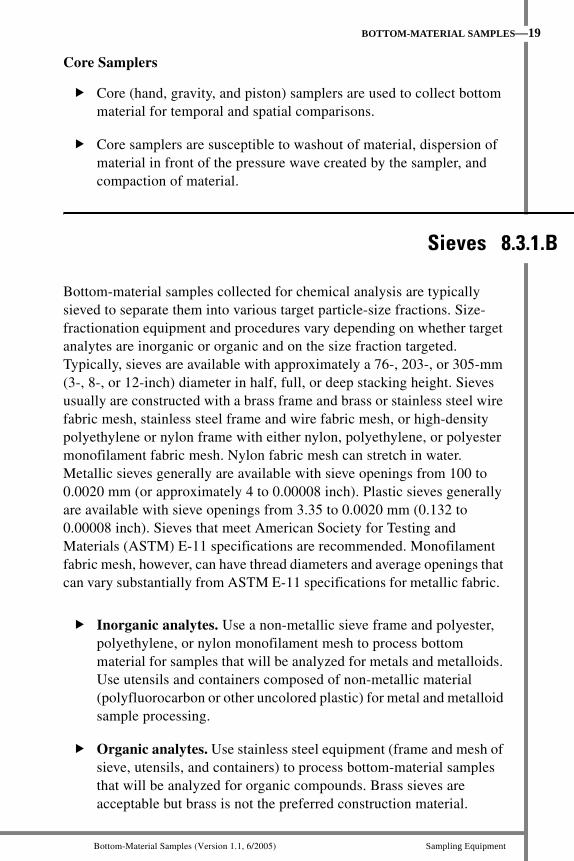
Core Samplers
Core (hand, gravity, and piston) samplers are used to collect bottom material for temporal and spatial comparisons.
Core samplers are susceptible to washout of material, dispersion of material in front of the pressure wave created by the sampler, and compaction of material.
Bottom-material samples collected for chemical analysis are typically sieved to separate them into various target particle-size fractions. Size-fractionation equipment and procedures vary depending on whether target analytes are inorganic or organic and on the size fraction targeted. Typically, sieves are available with approximately a 76-, 203-, or 305-mm (3-, 8-, or 12-inch) diameter in half, full, or deep stacking height. Sieves usually are constructed with a brass frame and brass or stainless steel wire fabric mesh, stainless steel frame and wire fabric mesh, or high-density polyethylene or nylon frame with either nylon, polyethylene, or polyester monofilament fabric mesh. Nylon fabric mesh can stretch in water. Metallic sieves generally are available with sieve openings from 100 to 0.0020 mm (or approximately 4 to 0.00008 inch). Plastic sieves generally are available with sieve openings from 3.35 to 0.0020 mm (0.132 to 0.00008 inch). Sieves that meet American Society for Testing and Materials (ASTM) E-11 specifications are recommended. Monofilament fabric mesh, however, can have thread diameters and average openings that can vary substantially from ASTM E-11 specifications for metallic fabric.
Inorganic analytes. Use a non-metallic sieve frame and polyester, polyethylene, or nylon monofilament mesh to process bottom material for samples that will be analyzed for metals and metalloids. Use utensils and containers composed of non-metallic material (polyfluorocarbon or other uncolored plastic) for metal and metalloid sample processing.
Organic analytes. Use stainless steel equipment (frame and mesh of sieve, utensils, and containers) to process bottom-material samples that will be analyzed for organic compounds. Brass sieves are acceptable but brass is not the preferred construction material.
Sieves 8.3.1.B
U.S. Geological Survey TWRI Book 9 Chapter A8. (Version 1.1, 6/2005)
20—BOTTOM-MATERIAL SAMPLES
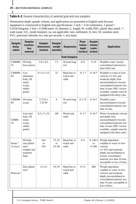
Table 8–2. General characteristics of selected grab and core samplers
[Penetration depth, sample volume, and applications are presented in English units because equipment is constructed to English-unit specifications: 1 inch = 2.54 centimeters, 1 pound = 0.4536 kilogram, 1 foot = 0.3048 meter. D, diameter; L, length; W, width; PDC, plastic dip coated; *, trade name; I.D., inside diameter; na, not applicable; mm, millimeter; ft, feet; SS, stainless steel; PVC, polyvinyl chloride; ft/s, feet per second; <, less than]
Samplerdesig-nation
Samplerconstruc-
tionmaterial
Sampler dimensions
(inches)
Sampler weight
(pounds) Suspension
Pene-trationdepth
(inches)
Sample volume (cubicinches)
Application
Grab Samplers
USBMH-53
SS body, brass piston
2 D x 8 L 7.5 46-inch-long rod
0–8 0–25 Wadable water, loosely consolidated material less than 0.063 mm.
USBMH-60
Cast aluminum body, SS rotary scoop, rubber gasket
8 x 4.5 x 22 32 Hand line or winch and cable
0–1.7 0–10.7 Wadable to water of slow velocity (<1 ft/s) and moderate depth; firm unconsolidated to loosely consolidated material, less than 16 mm; PDC version available; sampler must be equipped with safety yoke.
USBMH-80
SS rotary scoop
2.75 D x 3.25 W
8 56-inch-long rod
0–1.75 0–10.7 Wadable water; unconsolidated to loosely consolidated material, less than 16 mm.
USBM-54
Cast steel body, SS rotary scoop, rubber gasket
8.5 x 7 x 22 100 Winch and cable
0–1.7 0–10.7 Water of moderate velocity and depth; firm unconsolidated to loosely consolidated material, less than 16 mm; PDC version available, sampler must be equipped with safety yoke.
Ponar * (2 sizes)
SS body, zinc-plated steel weights and neoprene flaps
6x6or
9x9
15–22or
45–60
Hand line or winch and cable
0–4 0–146.4or
0–500
Weight dependent; wadable to water of slow velocity (<1 ft/s) and moderate depth; unconsolidated to loosely consolidated material, less than 16 mm; susceptible to loss of fines.
Petersen*
Zinc-plated steel
12 x12 39–93 Hand line or winch and cable
0–12 600 Weight dependent; wadable to water of slow velocity and moderate depth; unconsolidated to consolidated material, less than 16 mm; susceptible to loss of fines.

Bottom-Material Samples (Version 1.1, 6/2005) Sampling Equipment
BOTTOM-MATERIAL SAMPLES—21
Table 8–2. General characteristics of selected grab and core samplers—Continued
Samplerdesig-nation
Samplerconstruc-
tionmaterial
Sampler dimensions
(inches)
Sampler weight
(pounds) Suspension
Pene-trationdepth
(inches)
Sample volume (cubic
inches)
Application
Grab Samplers—Continued
Birge-Ekman* (4 sizes)
SS or brass
6x6x6or
6x6x9or
9x9x9or
12x12x12
16–25 or
21–35 or
47–68 or
100–150
Rod, hand line, or winch and cable
0–3or
0–4or
0–5or
0–6
0–216or
0–323or
0–729or
0–1,726
Wadable to water of slow velocity (< 1 ft/s) and moderate depth; soft unconsolidated material, less than 0.25 mm; susceptible to loss of fines; must penetrate perpendicular.
Shipek*
Cast alloy steel
4 x 6 x 6or
18.6 5 25.1 5 17.4
11or
135
Hand line or winch and cable
0–1.2or
0–4
0–30.5or
0–183
Wadable to water of moderate velocity and depth; unconsolidated to consolidated material, less than 0.50 mm; susceptible to loss of fines; PDC version available.
Van Veen* (2 sizes)
SS body, zinc-plated steel chain, neoprene flaps
13.8 x 27.6or
19.7 x 39.4
66–88or
143–187
Cable 0–12 0–11or
0–46
Wadable to water of mod-erate velocity and depth; soft unconsolidated mate-rial less than 0.25 mm.
Core Samplers
Hand
SS or SS core tubes; Lexan* or SS nose piece and SS or plastic core catcher
2 I.D.20–96 L
10–60 Handle 0–15 ft. L
0–96 0–300 Wadable to diver application, water of slow velocity (< 1 ft/s); soft to semi-firm unconsolidated material less than 0.25 mm; 2-inch core liners available in plastic and SS.
Ogeechee* (sand corer)
SS or SS core tubes; Lexan or SS nose piece and SS or plastic core catcher
2 I.D.20–96
10–60 Hand corer
0–96 0–300 Wadable to diver application, water of slow velocity (< 1 ft/s) and depth; soft to firm unconsolidated material less than 0.50 mm; 2- inch core liners available in plastic and SS.
Kajak-Brinkhurst [K-B]* (gravity corer)
SS, Lexan, or SS core tubes; Lexan or SS nose piece; SS or plastic core catcher; neoprene valve
2 I.D.20, 30 L
15–48 Hand line or winch and cable
0–30 0–90 Water with very slow velocity (< 1 ft/s); loosely consolidated material less than 0.063 mm; 2- inch core liners available in plastic and SS.

U.S. Geological Survey TWRI Book 9 Chapter A8. (Version 1.1, 6/2005)
22—BOTTOM-MATERIAL SAMPLES
Table 8–2. General characteristics of selected grab and core samplers—Continued
Samplerdesig-nation
Samplerconstruc-
tionmaterial
Sampler dimensions
(inches)
Sampler weight
(pounds) Suspension
Pene-trationdepth
(inches)
Sample volume (cubicinches)
Application
Core Samplers—Continued
Phleger* (gravity corer)
SS core tube, nose piece, core catcher; neoprene valve
1.4 I.D. 20 L
17.6–33 Hand line or winch and cable
0–20 0–40 Water with very slow velocity (< 1 ft/s); soft to firm unconsolidated material less than 0.50 mm; core liners available in plastic.
Ballchek* (gravity corer)
Bronze head, SS or PVC core tubes; Lexan* or SS nose piece and SS or plastic core catcher; plastic/ polyurethane valve
2–5 I.D. 30–96 L
Variable depending
on sizeand
construc-tion
material
Hand line or winch and cable
0–96 0–750 Water with very slow velocity (< 1 ft/s); loosely consolidated material, less than 0.063 mm; core liners available in plastic and SS.
Benthos* (gravity corer)
Steel core tube, nose piece, and core catcher
2.6 I.D.120 L
55–320 Winch and cable
120 0–490 Water with very slow velocity (< 1 ft/s); loosely consolidated material less than 0.063 mm; core liners available in plastic.
Alpine* (gravity corer)
Steel core tube, nose piece, core catcher, and neoprene valve
1.6 I.D. 72 L
242–342 Winch and cable
72 0–180 Water with very slow velocity (< 1 ft/s); loosely consolidated material, less than 0.063 mm; core liners available in plastic; inconsistent vertical penetration.
Box
SS with optional acrylic box liner
6 x 6 x 9 31–100 Winch and cable
9 0–300 Water of slow velocity (< 1 ft/s) and moderate depth; unconsolidated material, less than 0.25 mm.
Piston
SS or plastic core tubes; Lexan or SS nose piece; SS or plastic core catcher
1–5 I.D. 40–800 L
25–500 Hand line or winch and cable
0–80 0–6,200 Water with very slow velocity (< 1 ft/s); loosely consolidated material, less than 0.25 mm; core liners available in plastic.
Vibracorer*
Variable 2–3 I.D.40–500 L
100–300 Frame 0–500 0–2,300 Water with very slow velocity (< 1 ft/s); loosely consolidated material, less than 16 mm; assembly might require scuba divers.
Bottom-Material Samples (Version 1.1, 6/2005) Sampling Equipment
BOTTOM-MATERIAL SAMPLES—23
Decontamination is the cleaning process used to remove potential contaminants from equipment. Do not collect, process, or handle samples until the equipment has been completely decontaminated.
Decontaminate all new and used equipment to be used for sample collection, processing, and handling. Equipment also should be decontaminated in the field immediately after completion of sampling. If complete equipment decontamination is not possible in the field, rinse equipment thoroughly with water at the field site and store for complete decontamination. Document decontamination procedures in study notes or on the field form.
Before starting equipment decontamination, check the construction material of field equipment, cleaning equipment, and supplies:
If your samples will be analyzed for metals and metalloids, do not use metallic equipment and supplies. Use nonreactive cleaning equipment and supplies composed of uncolored or white polypropylene, polyethylene, polyfluorocarbon, or some other suitable non-metallic material.
If your samples will be analyzed for organic compounds, do not use reactive plastic equipment and supplies. Use nonreactive cleaning equipment and supplies composed of metal, glass, or polyfluorocarbon materials.
A list of equipment and supplies used to clean and maintain equipment is given in section 8.7.
DECONTAMINATION 8.3.2

U.S. Geological Survey TWRI Book 9 Chapter A8. (Version 1.1, 6/2005)
24—BOTTOM-MATERIAL SAMPLES
Use the following three-step decontamination procedure (put on disposable gloves and other appropriate protective clothing before starting):
1. Wash equipment thoroughly with phosphate-free detergent.
2. Rinse with copious quantities of tap water.
• If equipment has recalcitrant mineral residues, rinse nonmetallic equipment with a dilute acid solution.
• If equipment has recalcitrant oily residues, rinse nonplastic equipment parts with pesticide-grade methanol.
3. Rinse with copious quantities of deionized water.
Store cleaned equipment inside sealable polyfluorocarbon or other uncolored plastic bags.
Improperly cleaned equipment is a source of sample contamination.
CAUTION: Before handling chemicals, refer to Material Safety Data Sheets for proper precautions.
Wear appropriate safety gloves, glasses, and protective clothing.
Clean chemical spills immediately.
Dispose chemical solutions according to regulations.

Bottom-Material Samples (Version 1.1, 6/2005) Sample Collecton
CLEANING OF EQUIPMENT FOR WATER SAMPLING—25
The field team is responsible for determining what will comprise a representative sample with respect to study objectives and site characteristics. The bottom-material sample must resemble the native bottom material without loss of physical, chemical, and biological structure. The degree to which a single sample can be considered representative depends on many factors, including:
Temporal and spatial homogeneity of the water body.
Number and distribution of subareas sampled at a site.
Method (statistical or deterministic) used to select sampling sites and subareas.
Size of individual samples.
Technique used to collect samples and results from the quality-control sample analysis.
Generic USGS data-collection efforts typically take a whole-system approach, meaning that data are collected using methods to ensure that an entire stream reach is represented. Special studies may require an approach for which samples are representative of a specific, targeted environment or portion of an aqueous system, instead of the entire system. Criteria and considerations for collecting a representative sample are summarized in table 8–3.
SAMPLE COLLECTION 8.4
Errors introduced by sampling can be the most significant in the entire data-collection process:
always collect replicate samples for quality control.
CAUTION: Do not jeopardize personal safety when working from boats, planes,
bridges; on ice; or in flowing water.

U.S. Geological Survey TWRI Book 9 Chapter A8. (Version 1.1, 6/2005)
26—BOTTOM-MATERIAL SAMPLES
Table 8–3. Criteria and considerations for collecting a representative sample of bottom material
Aspects of sample collection
Criteria and considerations
Equipment
• Sampling equipment penetration must be deep enough to provide a sample that meets project objectives.
• Sampling equipment must be completely closed after proper penetration.
• Weight of sampler (too light could produce improper deployment of sampler).
Techniques and methods
• Bottom-material disturbance prior to equipment deployment must be avoided.
• Quantities of bottom material enclosed each time sampling equipment is deployed should be approximately equal.
• Speed of sampler through water column (too fast will produce too large a shock wave in front of descending sampler and greater potential for sampler malfunction, but too slow could produce insufficient penetration, especially with core samplers).
Sampling environment
• Depth of water column (ensure adequate cable length to control speed of sampler deployment and personal safety when wading).
• Physical, chemical, and biological character of water column above sample-collection site (especially presence or absence of oxygen).
• Velocity of water currents (too fast could produce improper deployment of sampler).
• Sampling platform stability (such as boat, ice, float plane).
8.4.1 SAMPLING PROCEDURESBottom-material samples must meet the sampling objective of the study. Use procedures that minimize sample disturbance and prevent contamination. Be aware that no procedure for collecting bottom-material samples can be used for every type of study objective and environmental setting.
Complete the following steps before beginning to sample:
1. Select sampling locations (refer to section 8.2 and table 8–4).
a. Examine each site to be sampled in a manner that minimizes the site’s problematic characteristics and maximizes its beneficial char-acteristics.
• For perennial flowing water, consider collecting bottom-material samples after extended low-flow periods.
• For ephemeral flowing water, consider collecting bottom-material samples just after a runoff event.

Bottom-Material Samples (Version 1.1, 6/2005) Sample Collecton
CLEANING OF EQUIPMENT FOR WATER SAMPLING—27
b. Inspect the body of water visually and bathymetrically.
• Observe (or refer to historical information on) size and shape of the area, land use, tributary and runoff characteristics, geology, point and diffuse sources of contamination, hydraulics, water depth, and fluvial-sediment transport characteristics.
• Use aids for site inspection, such as side-scan sonar, sub-bottom profiler or acoustic survey (echo, seismic reflections and refraction), or reconnaissance sampling.
c. Determine number of subareas according to the accuracy required by study objectives.
• If a transect is split by natural or manmade barriers, treat each channel as a separate entity.
• Use the two-step method described in the TECHNICAL NOTE in section 8.2.2 to obtain a statistically based estimate of the appropriate number of subareas.
d. If using statistical design methods, divide the site into numbered subareas with a sampling point located in each subarea. Collect samples in the center of numbered sites that correspond to random numbers when using stratified random, stochastic random, or sys-tematic regular methods for design of a sample-collection net-work.
e. Use global positioning equipment and detailed maps to indicate site location and subareas or their sampling points.
2. Select, assemble, and set out the proper sampling, support, and safety equipment (such as floatation jackets, cable cutter, cones, signs, buoys).
• Use quality-assured sample containers (jars, bottles, or cartons) supplied by the USGS National Water Quality Laboratory (NWQL) through One-Stop Shopping for USGS studies.
• Ensure that the weight of a sampler is sufficient to allow proper penetration into the bottom and deployment.
• Sampler cable or line must be properly secured to sampling platform and sampler in order to avoid losing the sampler.
• Limitations of using scuba gear are depth, visibility, currents, and personal safety.
Great care must be exercised when using multipurpose equipment for bottom-material sampling and sample processing. Consider following the Clean Hands/Dirty Hands technique described in NFM 4.0.1 and Horowitz and others (1994) when using metal support equipment.

U.S. Geological Survey TWRI Book 9 Chapter A8. (Version 1.1, 6/2005)
28—BOTTOM-MATERIAL SAMPLES
Table 8–4. Procedures for selecting sampling locations using selected nonstatistical and statistical methods
Method Procedure
Nonstatistical method
Deterministic
1. Divide total area to be sampled into subareas, using site-characteristics information, study objectives, and professional judgment.
2. Select location and number of subareas within total area on predetermined non-random, biased criteria.
Statistical methods
Stratified random
1. Divide total area to be sampled into numbered subareas, using site-characteristics information, study objectives, and professional judgment.
2. Determine number of subareas required for sampling.
3. Select subareas using random numbers.
4. Collect sample in center of subarea (sampling point) that corresponds to a random number.
Stochastic random
1. Divide total area to be sampled into equally sized and numbered subareas.
2. Determine number of subareas required for sampling.
3. Select subareas using random numbers.
4. Collect samples in center of numbered subareas (sampling point) that correspond to random numbers.
Systematic regular
1. Divide total area to be sampled into regularly spaced subareas.
2. Determine number of subareas required for sampling.
3. Select subareas using random numbers.
4. Sample at center of each subarea (sampling point), keeping a constant distance between sampling locations.
Fixed transect
1. Sample along a transect at fixed and predetermined subareas (sampling points). These do not need to be at constant intervals. Sampling points can be established to coincide with the location of equal-width-increment (EWI) water sampling verticals.
2. Visually inspect body of water from bank to bank, observing and noting velocity, width, and depth distribution, as well as apparent distribution of sediment in cross section.
3. Determine width from a tagline or from increment markings on cableways or upstream bridge railings.
4. Decide minimum number of increments needed to adequately define bottom material through the transect and also to satisfy study needs and objectives. Where feasible, use a minimum of 10 EWI increments.
Bottom-Material Samples (Version 1.1, 6/2005) Sample Collecton
CLEANING OF EQUIPMENT FOR WATER SAMPLING—29
Begin sampling after sampling points have been located and equipment set up:
1. Move sampling and support equipment to the first station (sampling point) to be sampled and to each subsequent sampling point, in order, as samples are collected.
• Avoid disturbance to bottom material at sampling points, caused by wading, movement of vessel and motor, and mixing or compaction of bottom material. Sample disturbance can re-sult from a pressure wave from sampler, frictional resistance during penetration of bottom by sampler, skewed sampler penetration of bottom, and loss (washout) of sample during retrieval.
• If wading, always approach sampling point from downstream.
2. Make field measurements in water column above sampling point to determine physical, chemical, and biological character of water (especially presence or absence of oxygen). To minimize disturbance to bottom material, make such measurements after collecting bottom-material samples (this precaution applies especially if transect will be waded).
3. Collect samples.
If using a grab sampler:
a. Cock bucket in open position.
b. Steadily lower sampler to bottom, avoiding any jerking motions that would cause the cable to slacken and the bucket to close prematurely.
c. Upon impact with bottom, tension on suspension cable or han-dline will be released, allowing spring-loaded sample bucket to scoop a sample. (With some grab samplers, sample bucket most often scoops sample from bottom as sampler is lifted. Therefore, sampler should be lifted slowly to allow bucket to close on the sample before raising it quickly to water surface.)
d. Discard sample and resample if grab sampler did not close completely or if there was an obvious loss of fine material.
CAUTION: Keep hands away from the opening of the
sampling bucket at all times!

U.S. Geological Survey TWRI Book 9 Chapter A8. (Version 1.1, 6/2005)
30—BOTTOM-MATERIAL SAMPLES
If using a core sampler:
a. Use box corers in a similar manner as grab samplers and use gravity, piston, and vibracorer samplers as described by the manufacturer. (Gravity corers generally are not recom-mended for flowing waters.)
b. Use hand coring when wading or when using scuba gear in nonwadeable water.
• When wading, place sampler on bottom and capture bottom material by pushing sampler into bottom. Avoid hammering.
• Carefully retrieve hand corer and immediately cap it to prevent loss of sample.
• If a core liner is used, remove liner from corer and stopper both ends.
4. Resample if much of the fine-grained material is lost during sampler retrieval.
5. Transfer samples from sampler to either an appropriate sample container or appropriate compositing device using nonreactive utensils and containers and the instructions in section 8.5. Before transferring any extruded core material to an appropri-ate container, proceed as directed in section 8.5. Repeat for samples collected from each sampling point. Field extrusion is not recommended.
• When transferring sample from sampler to a nonreactive, appropriate sample container or compositing device, ensure that all particles are removed and transferred.
• When transferring sample aliquots from sampler to sample container, ensure that each subsample is “representative.”

Bottom-Material Samples (Version 1.1, 6/2005) Sample Collecton
CLEANING OF EQUIPMENT FOR WATER SAMPLING—31
6. Repeat sample-collection procedure at each sampling point across the transect.
• You will need to collect and homogenize at least three rep-licate grab samples or three subsamples from a core at each sampling point to make defensible statistical inferences. More replicates may be necessary to achieve a desired level of precision.
• A composite of an entire core length generally is not recommended.
7. Label each sample container with the following information:
• Station/sampling point number and name.
• Date.
• Mean time and gage height (or discharge) for period of sample collection.
• Station/sampling point location, such as bridge and tagline.
• Depth of water at sampling point.
• Sample collection method, sampler used, analyses requested, and other information requested by laboratory performing sample analysis.
• Number of samples in container if samples are composited.
• Initials of sample collector.
8. Read and record gage height and time at which sample collec-tion was completed.
9. Complete sample processing and preservation, where applica-ble. Refer to section 8.5.
10. Calculate and record in field notes the mean time and gage height for the period of sample collection. In field notes, record texture, color, odor, and any other characteristics of the bottom material.
11. Disassemble samplers for decontamination or routine clean-ing. Decontaminate samplers as described in section 8.3.2. Always store grab samplers in the closed position.

U.S. Geological Survey TWRI Book 9 Chapter A8. (Version 1.1, 6/2005)
32—BOTTOM-MATERIAL SAMPLES
Quality-control samples are a requisite for any sample-collection and analysis program. Quality-assurance procedures involving quality-control samples are not to be viewed as an option. Quality-control procedures for bottom-material sampling will entail use of split field samples and concurrent replicate field samples.
The recommended minimum quality-control samples is 10 percent of the total number of samples collected per year (total for all field-collected quality-control samples).
For long-term projects that entail multiple sampling sites, an attempt should be made, during the life of the project, to collect at least one set of field quality-control samples at every sampling site used for that project.
If seasonal variations are suspected, an attempt also should be made to collect field quality-control samples under various seasonal conditions.
Split samples are designed to determine analytical precision for chemical constituents in a “real-world” sample matrix. A split sample is an aliquot of an already collected, homogenized, processed, and preserved sample. Split samples are prepared by partitioning a larger volume of processed sample from one container into equal subsamples; samples are split in an enclosed environment and using equipment and methods that preclude sample contamination.
8.4.2 QUALITY-CONTROL PROCEDURES AND REQUIREMENTS
8.4.2.A Split Samples

Bottom-Material Samples (Version 1.1, 6/2005) Sample Collecton
CLEANING OF EQUIPMENT FOR WATER SAMPLING—33
Concurrent replicate samples are two samples that are collected using identical methodology, as closely together in time and space as possible (Horowitz and others, 1994). Concurrent sample data are intended to provide the user with a measure of sampling precision and (or) are intended to indicate inhomogeneities in the system being sampled.
To collect and process concurrent replicate samples:
1. Starting with the first sampling point, collect a sample for compositing and place it in a field-rinsed compositing device.
2. Reoccupy (in close proximity) the first sampling point, collect a second sample, and place it in a second field-rinsed compositing device.
3. Go to the second sampling point, collect a sample, and place it in the second compositing device.
4. Reoccupy (in close proximity) the second sampling point, collect a sample, and place it in the first compositing device.
5. Continue to sample remaining sampling points in this manner, continuing to alternate placement of samples in first and second compositing devices.
6. After all sampling points have been visited, two compositing devices will contain an approximately equal volume of representative samples.
7. Process the first composited sample (see section 8.5); if a split field sample is needed, partition the sample into two appropriate sample containers, with one labeled “Site x, Sample 1, Split A” and the other labeled “Site x, Sample 1, Split B.”
8. Process the second sample, and then if a split field sample is needed, partition it into two appropriate sample containers, with one labeled “Site x, Sample 2, Split A” and the other labeled “Site x, Sample 2, Split B.”
Concurrent Replicate Samples 8.4.2.B

U.S. Geological Survey TWRI Book 9 Chapter A8. (Version 1.1, 6/2005)
34—BOTTOM-MATERIAL SAMPLES
Page left blank intentionally.

Bottom-Material Samples (Version 1.1, 6/2005) Sample Processing
BOTTOM-MATERIAL SAMPLES—35
Sample processing includes compositing and subsampling, sieving, phase separation, and sample preservation. Sample preservation normally consists of keeping the sample chilled to 4°C during shipping and storage, but also can involve processing oxygen-sensitive material under an inert-gas atmosphere or freeze drying the sample.
Use nonreactive equipment. Components of processing equipment need to be made of materials that will not contaminate or adsorb target analytes, and that will withstand cleaning solutions.
– Inorganic analytes. Use utensils, bowls, pans, and contain-ers composed of non-metallic material (polyfluorocarbon or other white or clear plastics).
– Organic analytes. Use utensils, bowls, pans, and containers composed of polyfluorocarbon, glass, or stainless steel.
Decontaminate all processing equipment as instructed in section 8.3.2.
Prepare for sample processing:
1. Park the field vehicle as far away from any nearby road(s) as possible and turn off motor (road dust and vehicle emissions can contaminate samples) in order to isolate the sample-processing area from potential contaminants.
2. Set up field-processing area. Appropriate areas include a bench set up in a van or a building conveniently located near the sampling site.
• Spread a large, uncolored or white plastic (non-metallic) sheet over the area where inorganic sample processing is taking place.
• Use heavy-duty aluminum sheeting over the area where organic sample processing is taking place.
• Keep sample-processing equipment covered (when not processing sample), and keep all sample containers covered or capped.
SAMPLE PROCESSING 8.5

U.S. Geological Survey TWRI Book 9 Chapter A8. (Version 1.1, 6/2005)
36—BOTTOM-MATERIAL SAMPLES
3. Field rinse processing equipment to ensure that all cleaning solution residues are removed, and to equilibrate equipment with sampling environment.
4. Wear powderless, disposable gloves while processing sample. Avoid contact with any potential source(s) of contamination. For example, keep gloved hands off any reactive (metal or plastic) objects when processing samples.
Depending on study objectives, bottom-material sampling methods generally produce a composite sample. When sampling for chemical constituents, the sample usually is subdivided at the field site into a number of subsamples, each equivalent in constituent concentrations.
Use the following procedures when sample compositing and subsampling (programmatic protocols might supersede some of the following procedures):
1. Transfer sample (or core segments) from each sampling station to an appropriate compositing device, sieve, or sample container. Be sure to remove and transfer all particles (use nonreactive utensils).
If using a grab sampler—Go to step 2 if sample is anaerobic and should not be aerated:
a. With a clean, nonreactive spatula, carefully homogenize the composite sample until texture and color appear uniform.
b. Using a nonreactive spatula, transfer a homogenized subsam-ple to sieve (see 8.5.2) or sample container.
If using a core sampler—Go to step 2 if sample is anaerobic and should not be aerated:
a. If pore water is not a concern, carefully siphon off water over-lying material in the corer or liner without disturbing the bottom-material/water interface. Leave a small amount of water at the bottom-material/water interface.
b. Use a core extruder to gently and slowly force core material out of the corer or core liner.
• If a core liner is used, visually inspect before extruding, sectioning, or slitting liner and core. Record features observed in field notes.
8.5.1 COMPOSITING AND SUBSAMPLING

Bottom-Material Samples (Version 1.1, 6/2005) Sample Processing
BOTTOM-MATERIAL SAMPLES—37
• Remove core catcher and check valve before extrusion process.
• Begin extrusion process from cutting end of barrel.
• Vertical extrusion is recommended.
c. Split the core lengthwise; visually inspect and make careful mea-surements of the core length and any layers that appear different.
• Note deformation and compaction.
• Note sloping layers, indicating possible nonperpendicular penetration of bottom.
• Note changes in stratigraphy, such as color and texture.
d. As core is extruded, carefully remove (section) required material with clean, non-reactive utensils and transfer material into an appropriate compositing device or sample container. Transfer only material that meets project and sampling objectives. It is recommended that only undisturbed core material (material from the interior of the core) be transferred.
e. If compositing core material or segments, follow procedures listed above for the grab sampler.
2. To process sample in an oxygen-free atmosphere:
a. Composite samples or extrude core under an oxygen-free atmo-sphere, such as a portable glove box filled with inert gas.
b. Extrude cores in an oxygen-free glove box.
c. Leave no headspace in sample containers.
d. Pack sample containers in airtight bags and maintain at 4°C.
3. Complete sample processing (and preservation, where applicable).
4. Calculate and record in field notes the mean time and gage height for the period of sample collection. Record in field notes the bottom-material texture, color, odor, and any other characteristics.
5. Disassemble and clean samplers, sieves, and other equipment.
Splitting and subsampling core material are best done in a controlled
environment—not in the field.

U.S. Geological Survey TWRI Book 9 Chapter A8. (Version 1.1, 6/2005)
38—BOTTOM-MATERIAL SAMPLES
To provide a better understanding of the environmental fate of inorganic and organic constituents, bottom-material samples collected for chemical analysis are typically sieved to separate them into various targeted particle-size fractions. Sieving of bottom material is known to disrupt chemical equilibrium of the sample.
Study objectives will dictate if sieving or another method of phase separation (such as centrifuge) is used. Data-collection needs will determine the type and construction of equipment, including the type, construction, diameter, and pore size of the sieve. Because sieving can be a labor-intensive process, it is very important to determine, in advance, the mass of sample required for chemical analysis so as not to over or under sieve. The type and quality of equipment used for processing of samples can affect quality of results (section 8.3).
TECHNICAL NOTE: Check with the NWQL before sending bottom-material samples to determine if the samples need to be pre-sieved through a 2.0-mm or smaller sieve. When sieving, use a minimal volume of native water.
Use the following procedures for sample sieving and subsampling:
1. Put on a pair of disposable gloves.
2. Homogenize the composited sample, using appropriate, nonreactive processing equipment:
a. Decant excess water from sample into an appropriate, nonre-active wash bottle, being careful not to lose fine material.
b. Visually inspect homogenized composite and record color and texture information in field notes.
3. Select an appropriate, nonreactive sieve or nest of sieves:
Inorganic constituents.
• Pre-sieve through a 2.0-mm or smaller sieve.
• Nest sieves to facilitate sieving process for finer fractions.
• Use uncolored or white non-metallic sieve and utensils to process bottom material for samples that will be analyzed for metals and metalloids.
• Use a stainless steel, uncolored, or white non-metallic sieve and utensils to process bottom material for samples that will be analyzed for nutrients, major ions, and radioisotopes.
8.5.2 SIEVING AND SAMPLE HANDLING

Bottom-Material Samples (Version 1.1, 6/2005) Sample Processing
BOTTOM-MATERIAL SAMPLES—39
Organic compounds.
• Pre-sieve through a 2.0-mm or smaller sieve.
• Nest sieves to facilitate sieving process for finer fractions.
• Use a stainless steel sieve and stainless-steel or polyfluorocar-bon utensils to process bottom material for samples that will be analyzed for organic compounds. Brass is acceptable but not recommended.
4. Wet sieve an aliquot of the composite as follows:
a. Place an appropriate, nonreactive container under selected sieve or nest of sieves.
b. Place an aliquot of composite sample on top of sieve(s).
c. Using a decontaminated squirt bottle, apply a minimal (<100 mL) amount of native water and any supernatant from the composite to remaining material on sieve(s).
• If native water has a conductivity of greater than 3,000 µS/cm, use deionized water or dry sieve. (Water other than native water may alter ion-exchangeable solute concentrations.)
• If necessary and without compromising sieve openings, shake sieve(s) from side-to-side to allow passage of material less than or equal to target particle-size fractions through sieve(s). Use an appropriate, nonreactive utensil to gently work target particle-size fractions through sieve(s).
• At sites with no native water, sieving should be done dry.
d. When all wash water has passed through the sieve, allow the material in the catchment container to settle.
e. Decant the supernatant into a wash bottle constructed of appro-priate material and continue to reuse the wash water to sieve any additional material until the required amount of material for analysis is obtained.
f. When the required amount of material is obtained, allow mate-rial in catchment container to settle.
• Allow sufficient time (while at the field site) for most, if not all, material in supernatant to settle.
• If fine, colloidal, or organic material fails to settle from supernatant, decant supernatant into a separate sample container and take container back to the lab for additional settling time or centrifugation.
• Do not discard supernatant until all fine or organic material has settled from supernatant.

U.S. Geological Survey TWRI Book 9 Chapter A8. (Version 1.1, 6/2005)
40—BOTTOM-MATERIAL SAMPLES
5. Visually inspect >2-mm fraction.
a. Record information in field notes:
• Relative volume of >2-mm fraction.
• Relative volume of organic matter.
• Relative abundance of shell fragments or other biological material.
• Relative abundance of grain coatings of red, yellow, and black oxides.
b. Retain >2-mm fraction for analysis if germane to study objec-tives; otherwise, discard.
6. If a 63-µm sieve is used, visually inspect >63-µm fraction.
a. Record information in field notes:
• Relative volume of >63-µm fraction.
• Relative volume of organic matter.
• Relative abundance of grain coatings of red, yellow, and black oxides.
• Relative abundance of shell fragments or other biological material.
b. Retain >63-µm fraction for analysis if germane to study objec-tives; otherwise, discard.
7. If subsamples are needed for several types of analytical requirements, thoroughly mix the sieved material with an appropriate, nonreactive utensil before subdividing into subsamples.
8. Transfer an appropriate amount of subsample to the appropriate sample container. It is recommended that all bottom-material samples be maintained at 4ºC during shipping and until analysis.
• Inorganic constituents. Use polypropylene container, chill, and maintain at 4ºC.
• Organic compounds. Use glass container with polyfluoro-carbon cap liner, chill, and maintain at 4ºC for shipment; 1-L baked glass bottles are needed for most organic analyses—check with the analyzing laboratory for the appropriate sample containers and sample designations.
9. Place samples on ice immediately after collection and again after processing.

Bottom-Material Samples (Version 1.1, 6/2005) Sample Packaging and Shipping
BOTTOM-MATERIAL SAMPLES—41
Generally, the shorter the time elapsed between sample collection and analysis, the more reliable will be the analytical results. Ship carefully packed samples as expeditiously as possible. Follow the packaging and shipping requirements of NWQL or other analyzing laboratory. For more information on shipping to NWQL, review NWQL Technical Memorandum 95.04 and Office of Water Quality Technical Memorandum 92.06 (see “Selected References and Technical Memorandums”).
SAMPLE PACKAGING 8.6 AND SHIPPING
For USGS studies:
Use quality-assured sample containers (jars, bottles, or cartons) supplied by NWQL.
Analytical Services Request (ASR) forms must be completed in the field and included with each shipping container (cooler or carton).
Do not seal the package without completing and including a laboratory analytical services request (ASR) form, as described in 8.6.3.
The following instructions apply to all studies:
1. Label each sample container using a permanent, waterproof marker, or use preprinted labels that will remain securely attached. Protect labels from water to prevent smearing.
• Each label must, at a minimum, include
– Site ID number
– Date and time (MM-DD-YY @ HHMM) of collection
– Sample designation code
SAMPLE IDENTIFICATION 8.6.1 AND PACKAGING

U.S. Geological Survey TWRI Book 9 Chapter A8. (Version 1.1, 6/2005)
42—BOTTOM-MATERIAL SAMPLES
• Do not put analytical requests such as schedule number and lab code adds or deletes on sample container instead of on the ASR form.
• Field personnel might find it more convenient to pre-label sample containers with preprinted labels before going into the field.
2. Securely fasten each cap. Do not use tape or paraffin on lids of jars containing organic samples—tape can contaminate the sample.
3. For chilled samples:
a. Pack samples in fresh ice for shipping with a volume of ice equal to at least the volume occupied by samples, but prefera-bly twice the volume of ice to samples. The amount of ice nec-essary will vary depending on the length of time in transit from the field to lab and the time of year. During summer, in partic-ular, the cooler and samples should be prechilled.
• Do not send samples chilled with “blue ice” or other types of commercial, refreezable containers.
• Do not chill sample containers with dry ice or with other substances that have a freezing point below 0ºC; this may cause sample containers to freeze and can result in ruined samples and (or) broken sample containers.
• Do not mix ice/water with packing materials. Keep ice/water and packing materials totally separate. Do not mix foam peanuts with ice for shipping.
b. Line all coolers with doubled (a bag within a bag) heavyweight trash bags. After samples and ice are placed in a doubled bag, seal each bag with a knot, or by gathering the top of the bag, folding it over, and securing with filament tape.
4. All samples can be shipped in coolers; samples not requiring chilling can be shipped in sturdy boxes, but these also should be lined with doubled heavyweight trash bags.
5. Always use adequate packaging materials to prevent breakage. NWQL will not accept samples shipped in vermiculite. Ship all glass jars in foam sleeves.

Bottom-Material Samples (Version 1.1, 6/2005) Sample Packaging and Shipping
BOTTOM-MATERIAL SAMPLES—43
6. When sending multiple sets of samples in one shipping container, label each set of samples with a letter of the alphabet (for example, A, B, C, and so forth) with each sample container in a set having the same letter as others in the set.
• Add this letter to the upper right hand corner of the ASR form.
• Recommended procedure is to place all samples from a sample set in a separate bag to keep them together.
7. Package all sample sets for a particular schedule in the same cooler/carton.
8. Do not ship nutrient samples in coolers with samples that have been treated with nitric-acid preservative. Contamination from the acids used in sample preservation may create false readings for some nutrient species.
9. When shipping a single set of samples or subsamples in multiple coolers (or other shipping containers), indicate the number of samples being shipped on the outside shipping label.
10. Remember to include an ASR form for each sample sent to the laboratory.
• Do not send samples in a shipping container without an ASR form.
• ASR forms must not be separated from samples.
• The ASR forms in different shipping containers may refer to the same site or station identification number, but the schedule and lab code information should apply only to samples shipped with the ASR form.
A sample container with an unreadable label results in a wasted sample.

U.S. Geological Survey TWRI Book 9 Chapter A8. (Version 1.1, 6/2005)
44—BOTTOM-MATERIAL SAMPLES
To prevent degradation of analytes by biological metabolism, it is recommended that bottom-material samples be shipped in ice-filled coolers (section 8.5 mentions possible exceptions to this recommendation).
The following instructions pertain to most bottom-material samples.
1. Ship chilled samples in coolers that are free of leaks.
• Carefully inspect cooler for leaks or damage.
• Spouts must be sealed, preferably with silicone or epoxy.
• Broken and/or leaky coolers must be replaced.
• Insulated water coolers, from 1 to 5 gallons in size, make good shipping containers.
• Larger volumes of chilled samples can be sent in ice chests as long as maximum weight restrictions of the carrier are not exceeded.
• NWQL will return, when feasible, recyclable packing materials (mesh bags, foam sleeves, and so forth) that are shipped to NWQL in coolers. NWQL will not return disposable packing materials.
2. To prevent leakage and maintain the integrity of the cooler, wrap tape around the cooler in order to secure the lid and seal the spigot.
3. With a permanent waterproof marker, label the inside of the cooler and cooler lid with your current return address and telephone number in case the shipping label is separated from the cooler.
4. Provide return address shipping labels in the cooler, along with an ASR form.
• The account to be billed for return shipment must be clearly marked on the shipping label.
• If no label is provided, or an incorrect account is on the label, the District’s default account will be charged a shipping fee.
8.6.2 SHIPPING CONTAINERS AND SAMPLE SHIPMENT
Bottom-Material Samples (Version 1.1, 6/2005) Sample Packaging and Shipping
BOTTOM-MATERIAL SAMPLES—455. If possible, samples should be sent to NWQL on a daily basis.
(Mailing samples daily by PRIORITY MAIL is usually an adequate means of ensuring a minimum transit time to NWQL.)
6. Whatever means of transportation is used, do not exceed restrictions on package size and weight.
• If the U.S. Postal Service is used, the shipper is responsible for compliance with postal laws and regulations.
• Preauthorization from the Postal Service may be needed to ship samples packed in ice.
7. Shipment of samples from hazardous waste sites must be authorized by the NWQL and must comply with Postal Service regulations.
Each shipping container (cooler or carton) must contain at least one ASR form and all
the samples associated with that form.
A NWQL Analytical Services Request (ASR) form must be included with each sample. To ensure correct processing of samples, all shipments must include an ASR form that refers only to samples in that shipment. It is mandatory to identify on the form highly contaminated or potentially hazardous samples so that proper precautions can be taken at the NWQL. Mandatory information on the ASR is indicated by an asterisk.
ANALYTICAL SERVICES REQUEST FORM 8.6.3
7. Prevent water damage to the ASR form from melting ice.
• Place the form inside a sealable plastic bag (doubled ziplock or whirlpack).
• Tape the bag containing the ASR form to the inside of cooler lid with filament tape.
If samples might contain hazardous chemicals,
note this in clear, bold letters on the comment
line at the bottom of the ASR form.
U.S. Geological Survey TWRI Book 9 Chapter A8. (Version 1.1, 6/2005)
46—BOTTOM-MATERIAL SAMPLES
Complete the ASR form as follows:
1. Use permanent, waterproof ink or laser-printed forms.
2. Each form must include:
• station id or unique number
• telephone number of study chief
• study chief/collector’s name
• state, district/user
• study account number
• begin date and time
• schedules and lab codes required to initiate analytical work for samples shipped with the form.
3. Check all ASR forms carefully for correct/current lab codes and schedules and compare with sample containers being shipped with the form.
4. At the bottom of each ASR form, indicate the total number of samples being sent to NWQL with the form.
5. At the bottom of each ASR form, include sample-designation codes of samples sent with the form.
6. When shipping multiple containers, include copies of the original ASR form with the appropriate lab codes and schedules to correspond with sample containers shipped in that container.
7. Prevent water damage to the ASR form from melting ice.
• Place the form inside a sealable plastic bag (doubled ziplock or whirlpack).
• Tape the bag containing the ASR form to the inside of cooler lid with filament tape.
8. Be sure to keep a carbon copy of the ASR form in study files.
9. Indicate the appropriate Sample Medium, Analysis Status, Analysis Source, Hydrologic Condition, Sample Type, and Hydrologic Event on ASR forms if analytical results are to be stored in the USGS National Water Information System (NWIS).

Bottom-Material Samples (Version 1.1, 6/2005) Checklist
BOTTOM-MATERIAL SAMPLES—47
Equipment and supplies commonly used to collect and process bottom-material samples are listed in table 8–5. The list may be modified to meet specific study needs.
Much of the equipment used in stream-gaging procedures also is used as support equipment for sampling bottom materials. A thorough description of the various types of support equipment is beyond the scope of this manual although some support equipment is listed on table 8–5. More detailed descriptions of support equipment can be found in Corbett and others (1943), Rantz and others (1982), Mudroch and MacKnight (1994), and Mudroch and Azcue (1995).
Equipment must be cleaned and tested before each field trip.
It is advisable to prepare a checklist so that essential and proper sampling equipment, including backup equipment and chemical reagents, are not forgotten.
CHECKLIST OF FIELD 8.7 EQUIPMENT AND SUPPLIES

U.S. Geological Survey TWRI Book 9 Chapter A8. (Version 1.1, 6/2005)
48—BOTTOM-MATERIAL SAMPLES
Table 8–5. Checklist of field equipment and supplies
✓ Item
Sampling Devices and Equipment
Bottom-material (core or grab) sampler
Bridgeboard, non-metallic; and nylon rope for bridgeboard
Core catchers
Core extractor/extruder
Core liners
Core liner caps
Core nose pieces
Support Equipment for Sampling
Cranes: Type A designed for weights of 150 pounds or less.
Crane bases:
• Four-wheel base should always be used when samplers weighing 75, 100, and 150 pounds are used with the Type A crane.
• Three-wheel base can be used with Type A crane.
Reel, hanger bars, and pins: (selection of type of reel should be based largely on maximum length and strength of cable that would be required)
• Type A reel has a fixed crank and no brake. Will accommodate 80 feet of 0.10-inch cable. The estimated practical maximum recommended load for this reel and cable combination is 100 pounds.
• Type B reel has a brake and two interchangeable handles. Will accommodate 144 feet of 0.10-inch cable, or 115 feet of 0.125-inch cable. The estimated practical maximum recommended load for this reel and cable combination is 200 pounds.
• Type E reel has a brake and two cranks for a 2-person operation. Will accommodate 200 feet of 0.10-inch cable, or 165 feet of 0.125-inch cable. The estimated practical maximum recommended load for this reel and cable combination is 200 pounds.
Sheeting, plastic for covering bridge rail
Winch and cable
Processing Equipment and Supplies
Sample containers, plastic, assorted [125, 250, 500, 1,000 milliliters (mL)]
Sample containers, glass or polyfluorocarbon, assorted (125, 250, 500, 1,000 mL)
Bottom-material splitting equipment:
• Containers, plastic or glass, large, sealable, wide mouth, polyfluorocarbon lined caps
• Funnel, large: plastic, stainless steel or glass
• Mixing bowls: flat bottom, large: polyfluorocarbon, plastic, or stainless steel
• Sieve cloth: stainless steel, brass, or plastic mesh
• Sieve frame: plastic, brass, or stainless steel
• Spoons, scoops, and spatulas: polyfluorocarbon, plastic, and/or stainless steel

Bottom-Material Samples (Version 1.1, 6/2005) Checklist
BOTTOM-MATERIAL SAMPLES—49
Table 8–5. Checklist of field equipment and supplies—Continued
✓ Item
Cleaning Equipment and Supplies
Acid spill kit
Apron
Basins, clear/white plastic (three per site)
Brushes, non-metallic
Deionized water
Detergent, phosphate free, 0.2 percent by volume
Eyewash
Gloves, noncontaminating (nonpowdered, disposable)
Safety glasses
Sealable plastic bags without colored closure strips
Tap water
Inorganic compounds:
• Bottles, wash, for deionized water
• Gloves, vinyl or latex, nonpowdered
• Tissues, lint free, extra large
• Tube or pipet jar, non-metallic
Organic compounds:
• Aluminum foil
• Glass bottles, baked (check with laboratory)
• Gloves, latex or nitrile, nonpowdered, disposable
Shipping Supplies
Bags, plastic ziplock, for Analytical Services Request forms
Bags, plastic, large
Boxes, sturdy
Coolers, 1 and 5 gallons
Forms, Analytical Services Request
Ice
Mailing labels (public and private shipping labels and return labels)
Pens, pencils, noncontaminating, waterproof, permanent
Sample container labels
Sleeves, foam or bubble wrap
Tape, fiber

U.S. Geological Survey TWRI Book 9 Chapter A8. (Version 1.1, 6/2005)
50—BOTTOM-MATERIAL SAMPLES
Table 8–5. Checklist of field equipment and supplies—Continued
✓ Item
Miscellaneous Equipment and Supplies
Boat, motor, paddles/poles/oars, trailer
Boots, hip
Bug repellent, non-aerosol
Calibration log books for all instruments
Calculator
Camera with film
Drinking water
Fire extinguishers
First aid kit
Flashlight with extra batteries
Forms, field documentation
Fuel
Gloves, vinyl or latex, nonpowdered
Historical discharge data for determining transit rates, verticals, depths
Highway emergency kit
Ice auger
Keys for security locks
Paper towels
Personal flotation device
Rain gear
Safety vest
Schedules, analytical with sample container requirements
Shovel
Soap, antibacterial
Spray, plastic dip coating
Station analysis and historical field measurement plots
Station description files and detailed site location map
Sunscreen
Tag line
Tape, polyfluorocarbon
Tool kit
Waders, chest

Bottom-Material Samples (Version 1.1, 6/2005) Conversion Factors and Abbreviations
CF—1
CONVERSION FACTORS AND ABBREVIATIONS
CONVERSION FACTORS
Multiply By To obtain
meter (m) 3.281 foot
micrometer (µm) 3.3 × 10⁻⁶ foot
millimeter (mm) 0.03937 inch
centimeter (cm) 0.3937 inch
liter (L) 0.2642 gallon
milliliter (mL) 0.0338 ounce, fluid
2.64 × 10⁻⁴ gallon
foot (ft) 0.3048 meter
pound, avoirdupois (lb) 0.4536 kilogram
Temperature: water and air temperature are given in degrees Celsius (°C), which can be converted to degrees Fahrenheit (°F) by use of the following equation:
°F = 1.8(°C) + 32
Specific electrical conductance of water is expressed in microsiemens per centime-ter at 25 degrees Celsius (µS/cm). This unit is equivalent to micromhos per centimeter (µmho/cm) at 25 degrees Celsius.
ABBREVIATIONSASR Analytical Services Request
lab Laboratory
NWIS National Water Information System
NWQL National Water Quality Laboratory, Denver, Colo.
TWRI Techniques of Water-Resources Investigations
USCG U.S. Coast Guard
USGS U.S. Geological Survey
WRD Water Resources Discipline of USGS

U.S. Geological Survey TWRI Book 9 Chapter A8. (Version 1.1, Version 6/2005)
2—CF
Page left blank intentionally.
Bottom-Material Samples (Version 1.1, 6/2005) Selected References
REF—1
SELECTED REFERENCES American Public Health Association, American Water Works
Association, and Water Environment Federation, 1992, Standard methods for the examination of water and wastewater (18th ed.): Washington, D.C., American Public Health Association, p. 1114–1122.
American Society for Testing and Materials, 1990, Standard guide for sampling fluvial sediment in motion, in Annual book of ASTM standards: Philadelphia, Pa., American Society for Testing and Materials, v. 11.02, p. 595–611.
______1994, Standard guide for collection, storage, characterization, and manipulation of sediments for toxicological testing: no. E 1391–94, Philadelphia, Pa., 21 p.
______1994, Standard guide for core sampling submerged, unconsolidated sediments: no. D 4823–95, Philadelphia, Pa., 13 p.
Baudo, R., 1990, Sediment sampling, mapping, and data analysis, inBaudo, R., Giesey, J., and Muntau, H., eds., Sediments: chemistry and toxicity of in-place pollutants: Ann Arbor, Mich., Lewis Publishers, p. 15.
Corbett, D.M., and others, 1943, Stream-gaging procedure: U.S. Geological Survey Water-Supply Paper 888, 245 p.
Crepin, J., and Johnson, R.L., 1993, Soil sampling for environmental assessment, in Carter, M.R., ed., Soil sampling and methods of analysis: Boca Raton, Fla., Lewis Publishers, p. 5.
Edwards, T.K., and Glysson, D.G., 1988, Field methods for measurement of fluvial sediment: U.S. Geological Survey Open-File Report 86–531, 118 p.
Feltz, H.R., 1980, Significance of bottom material data in evaluating water quality, in Baker, R., ed., Contaminants and sediments, v. 1: Ann Arbor Science Publishers, Inc., p. 271–287.
Feltz, H.R., and Culbertson, J.K., 1972, Summary procedures and problems in determining pesticide residues in the hydrologic environment: Pesticides Monitoring Journal, v. 6, no. 3, p. 171–178.
Gy, P., 1979, Sampling of particulate materials—theory and practice: New York, N.Y., Elsevier, 431 p.
Helsel, D.R., and Hirsch, R.M., 1995, Statistical methods in water resources: Amsterdam, The Netherlands, Elsevier Science, 529 p.
Horowitz, A.J., 1991, A primer on sediment-trace element chemistry: Chelsea, Mich., Lewis Publishers, 136 p.
SELECTED REFERENCES AND TECHNICAL MEMORANDUMS

U.S. Geological Survey TWRI Book 9 Chapter A8. (Version 1.1, 6/2005)
2—REF
Horowitz, A.J., Demas, C.R., Fitzgerald, K.K., Miller, T.L., and Rickert, D.A., 1994, U.S. Geological Survey protocol for the collection and processing of surface-water samples for the subsequent determination of inorganic constituents in filtered water: U.S. Geological Survey Open-File Report 94–539, 57 p.
Jenne, E.A., Kennedy, V.C., Burchard, J.M., Ball, J.W., 1980, Sediment collection and processing for selective extraction and for total trace element analysis: in Baker, R., ed., Contaminants and sediments, v. 2: Ann Arbor Science Publishers, Chap. 10, p. 169–190.
Keith, L.H., 1978, Principles of environmental sampling—ACS Professional Reference Book: Washington, D.C., American Chemical Society, 458 p.
Keith, L.H., ed., 1991, Compilation of EPA’s sampling and analysis methods: Chelsea, Mich., Lewis Publishers, 803 p.
Keith, L., Crummett, W., Deegan, J., Libby, R., Taylor, J., and Wentler, G., 1983, Principles of environmental analysis: Analytical Chemistry, v. 55, p. 2210– 2218.
Levison, A.A., 1974, Introduction to exploration geochemistry: Illinois, Applied Publishing Limited, 924 p.
Mudroch, A. and Azcue, J.M., 1995, Manual of aquatic sediment sampling: Boca Raton, Fla., Lewis Publishers, 219 p.
Mudroch, A. and MacKnight, S.D., eds., 1994, Handbook of techniques for aquatic sediments sampling (2d ed.); Boca Raton, Fla., Lewis Publishers, 236 p.
Natrella, M.G., 1966, Experimental statistics: National Bureau of Standards Handbook 91, U.S. Department of Commerce, Washington, D.C., U.S. Government Printing Office, p. 2–9 to 2–11.
Norris, J., 1988, Techniques for sampling surface and industrial waters: special considerations and choices, in Keith, L.H., ed., Principles of environmental sampling: Washington, D.C., American Chemical Society, p. 247–253.
Plumb, R., Jr., 1981, Procedures for handling and chemical analysis of sediment and water samples: Vicksburg, Miss., Environmental Laboratory, U.S. Army Engineer Waterways Experiment Station, Technical Report EPA/CE-81-1, p. 3–73 to 3–76.
Rantz, S.E., and others, 1982, Measurement and computation of streamflow, Volume 1, measurement of stage and discharge: U.S. Geological Survey Water–Supply Paper 2175, 284 p.
Shelton, L.R., 1994, Field guide for collecting and processing stream-water samples for the National Water-Quality Assessment program: U.S. Geological Survey Open-File Report 94–455, 42 p.
Shelton, L.R., and Capel, P.D., 1994, Guidelines for collecting and processing samples of stream bed sediment for analysis of trace elements and organic contaminants for the National Water-Quality Assessment program: U.S. Geological Survey Open-File Report 94–458, 20 p.

Bottom-Material Samples (Version 1.1, 6/2005) Selected References
REF—3
Sly, P.G., 1969, Bottom sediment sampling: Proceedings 12th Conference on Great Lakes Research, International Association of Great Lakes Research, p. 883–898.
U.S. Environmental Protection Agency, 1980, Samplers and sampling procedures for hazardous waste stream: EPA 600/ 2–80–018.
______1982a, Sampling protocols for collecting surface water, bed sediment, bivalves, and fish for priority pollutant analysis: Washington, D.C., Final Draft Report, Office of Water Regulations and Standards Monitoring and Data Support Division.
U.S. Environmental Protection Agency, 1982b, Handbook for sampling and sample preservation of water and wastewater: Cincinnati, Ohio, Environment Monitoring and Support Laboratory, EPA 600/ 4-82-029, 402 p.
______1982c, Handbook for sampling and sample preservation of water and wastewater: Cincinnati, Ohio, Environment Monitoring and Support Laboratory, EPA 600/4–82–029, p. 251–254.
______1983a, Addendum to Handbook for sampling and sample preservation of water and wastewater: Cincinnati, Ohio, Environment Monitoring and Support Laboratory, EPA 600/ 4–82–029, 28 p.
______1983b, Preparation of soil sampling protocols: Las Vegas, Nev., Environment Monitoring and Support Laboratory, EPA 600/4–83–020, 112 p.
______1987, A compendium of superfund field operations methods: Washington, DC., Office of Emergency and Remedial Response, EPA/540–P–87/001, 508 p.
______1989, Soil sampling quality assurance user’s guide: Las Vegas, Nev., Environment Monitoring and Support Laboratory, EPA 600/8–89–046, 268 p.
U.S. Geological Survey, 1978, Sediment, chap. 3 in U.S. Geological Survey, National handbook of recommended methods for water-data acquisition: p. 3–1 to 3–100.
______1984, Chemical and physical quality of water and sediment, chap. 5, in U.S. Geological Survey, National handbook of recommended methods for water-data acquisition: p. 5–1 to 5–194.
______Techniques of Water-Resources Investigations Reports, accessed June 15, 2005, at http://water.usgs.gov/pubs/twri/.
Ward, J.R., and Harr, C.A., 1990, Methods for collection and processing of surface-water and bed-material samples for physical and chemical analyses: U.S. Geological Survey Open-File Report 90-140, 71 p.
Wells, F.C., Gibbons, W.J., and Dorsey, M.E., 1990, Guidelines for collection and field analysis of water-quality samples from streams in Texas: U.S. Geological Survey Open-File Report 90-127, 79 p.

U.S. Geological Survey TWRI Book 9 Chapter A8. (Version 1.1, 6/2005)
4—REF
TECHNICAL MEMORANDUMS OF THE U.S. GEOLOGICAL SURVEY, WATER DISCIPLINE
The following memorandums are available electronically on the Internet through the USGS Web site at
http://water.usgs.gov/admin/memo/ (accessed April 2005).
National Water Quality Laboratory Technical Memorandum 95.04, Shipping Samples to the National Water Quality Laboratory, December 2, 1994, 7 p.
Office of Water Quality Technical Memorandum 92.06, REPORTS—Report of Committee on Sample Shipping Integrity and Cost, March 20, 1992, 22 p.