chapter 9 lecture - radiator
TRANSCRIPT
Chapter 9: Cooling Systems
BAE 599 - Lecture 9

Cooling Systems
Exhaust gas temperatures often exceed the melting point of materials utilized to make the pistons and cylinder walls.
Cooling is needed to reduce the likelihood of cylinder head cracking, cylinder wall scoring, ring sticking, or piston seizing.
Engines may either be water- or air-cooled.

Heat Loads
Heat load can be summed for several components,
where the subscripts CC, IC, OC and AC reference heat rejected by combustion chambers, inter-cooler, oil cooler, and air conditioner, respectively.
ACOCICCCT EEEEE

Cooling
First three terms, combined, are between 60 to 94% of the brake power.
Air conditioner load (32 C) is 7 kW. Cylinder temperatures must be kept
below 220 C to inure oil film does not break down.

Water Cooling
Manufacturer usually selects one supplier for cooling system – they are cooling specialists.
Critical values such as water flow, air flow and heat exchanger capacity are sized at rated engine speed and power.

Water Flow
Heat carrying capacity of radiator is estimated as,
where QW is coolant flow rate.
60WWWW
RW
TCQE

Coolant Flow Rate
Typical coolant flow rates are 1.3 to 2.5 L/min/kW.
Centrifugal pumps are used to move water.
Discharge of pump is into cylinder block.
Natural circulation causes water to rise to top of cylinder head – moves from head to radaitor.

Typical Radiator

Compact Size - Equipment Design Options

Radiator Design
Typical flow rates of 1.4 kg/min/tube. These flow rates are at saturation – little or
no additional heat transfer. Total tube numbers can be determined
using the previous equation for total flow rate and the rule-of-thumb above.
Tubes are rectangular in cross-section with 1:4 ratio.
Tube spacing in heavy-duty radiators is 1.6 cm.
Rows of tubes are staggered.

Radiator Design
Tubes may be aligned in rows for high particulate environments.
Fins used to increase heat transfer rate – more fins/cm is better.
Maximum fin spacing limit is 3.5 fins/cm, although may be reduced to 1.5 fin/cm for harvesters.
Frontal area must be large enough to transfer heat – rule of thumb 20-30 cm2 per kW brake power.

Fig. 9.1: Radiator Cut-Away
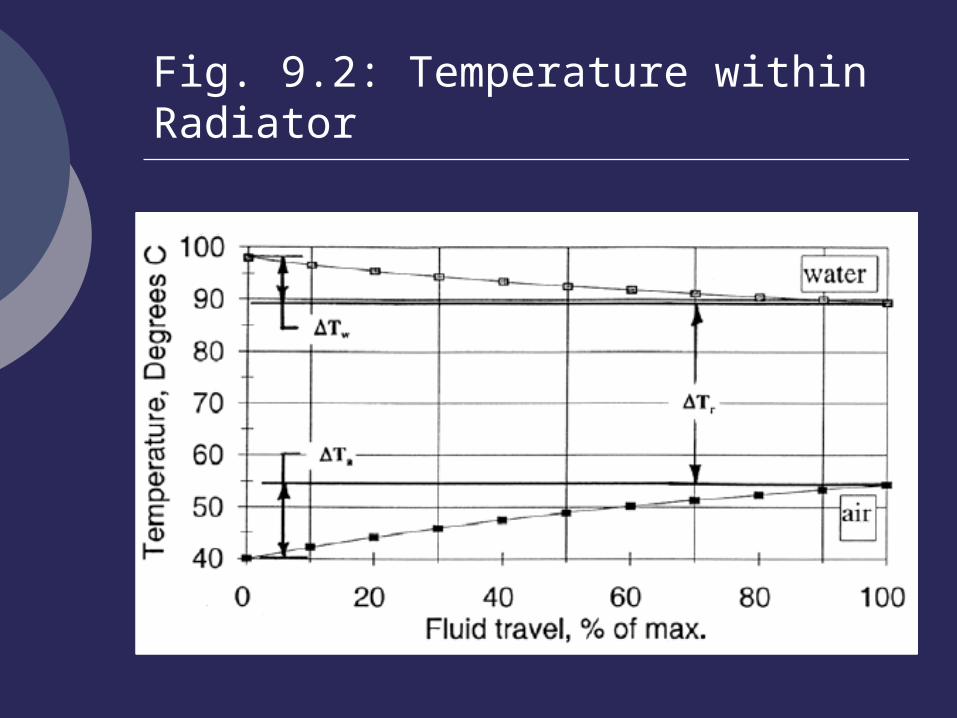
Fig. 9.2: Temperature within Radiator

Considerations
Coolant systems are often pressurized to prevent coolant boiling.
Upper engine temperature must observed.
Radiator tanks must be able to handle a 5% increase in volume as coolant expands upon heating.
Tank volume must be great enough to permit 200 changes of coolant per minute.

Coolant Boiling Point
The coolant boiling point can be estimated as,
where Cconc is the concentration of ethylene glycol.
400367.0053.0100 2 p
CCT concconcBP

Comments
Radiators can be pressurized to 100 kPa, although 50 kPa is more common.
For every 4 kPa change in system operating pressure, there is a 1 C change in operating temperature.
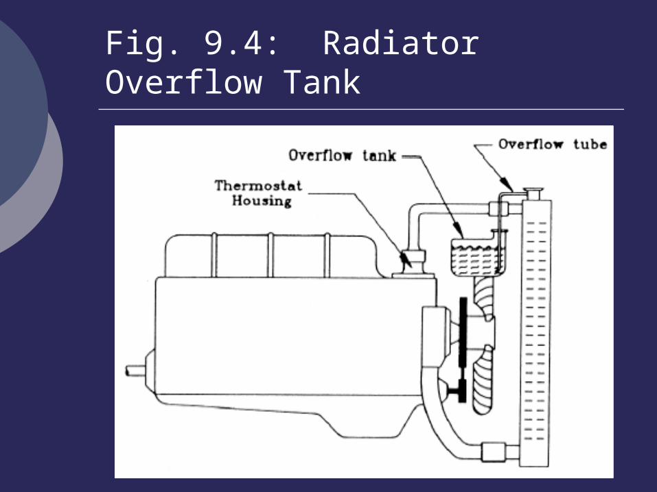
Fig. 9.4: Radiator Overflow Tank
Airflow Rate
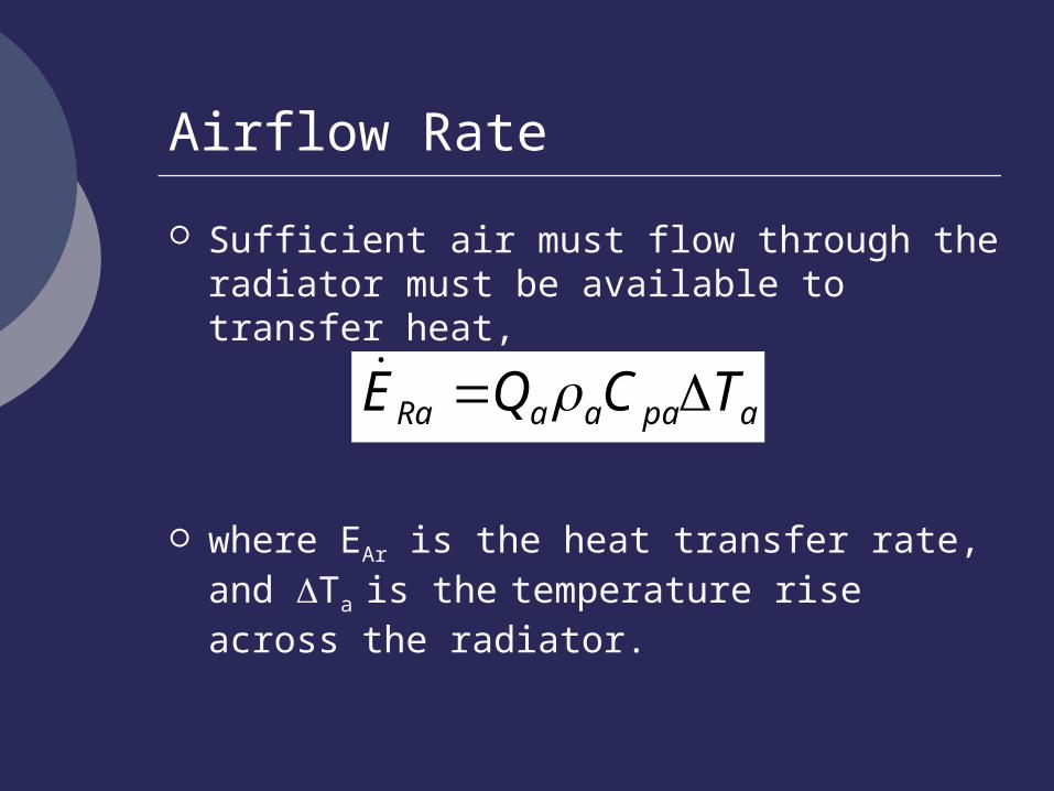
Sufficient air must flow through the radiator must be available to transfer heat,
where EAr is the heat transfer rate, and Ta
is the temperature rise across the radiator.
apaaaRa TCQE
Air Density
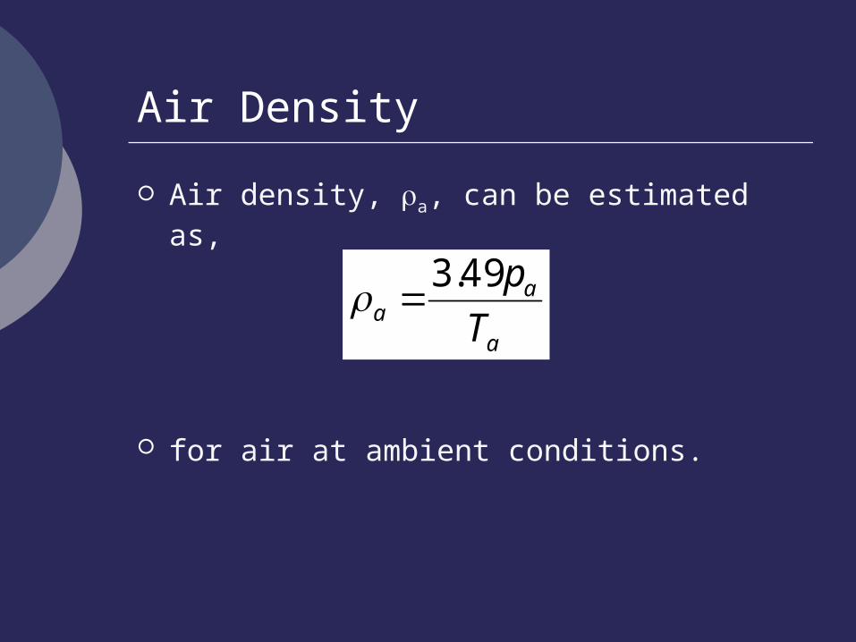
Air density, a, can be estimated as,
for air at ambient conditions.
a
aa T
p49.3

Comments
A reasonable temperature rise across the radiator is 15 to 20 C.
Must use fan curves once airflow rate is determined.
Fan curves are developed for standard conditions (101.2 kPa and 20 C).

Fig. 9.5: Example Fan Curve

Standard Air Pressure at Other Elevations
Standard air pressure at other elevations is approximated as,
where h is the altitude in m.
hpatm 01116.01.101
Correction of Fan Power
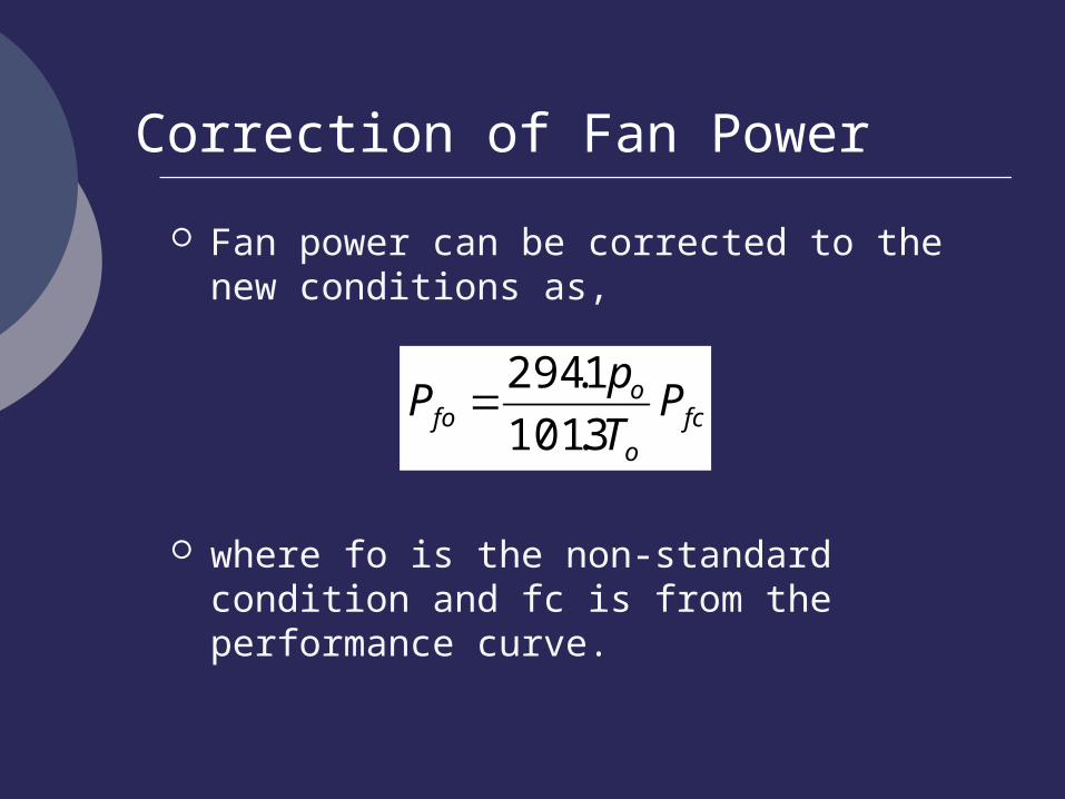
Fan power can be corrected to the new conditions as,
where fo is the non-standard condition and fc is from the performance curve.
fco
ofo P
T
pP
3.101
1.294

Fan Laws
Fan laws can be utilized to look at other fan configurations
3
fc
fn
fc
fn
fc
fn
D
D
N
N
Q
Q22
fc
fn
fc
fn
fc
fn
D
D
N
N
p
p
53
fc
fn
fc
fn
fc
fn
D
D
N
N
P
P

Comments
Shroud should be fitted between radiator and fan.
Need 10 cm clearance minimum between fan and radiator.
Peripheral clearance between fan and shroud should range from 0.6 to 1.25 cm.
Performance curves are generated for depth of fan penetration into shroud.

Coolants
Ethylene Glycol (C2H6O2) is the primary coolant utilized in engines today.
Typical mixtures are 50% water and 50% ethylene glycol.
Chemical inhibitors, that are alkaline, are added to the coolant to eliminate acid formation.

Coolants
Ethylene glycol raises the boiling point and lower the freezing point.
Additives reduce cavitation – a major source of cylinder wall pitting.
Other additive inhibit rust and corrosion.
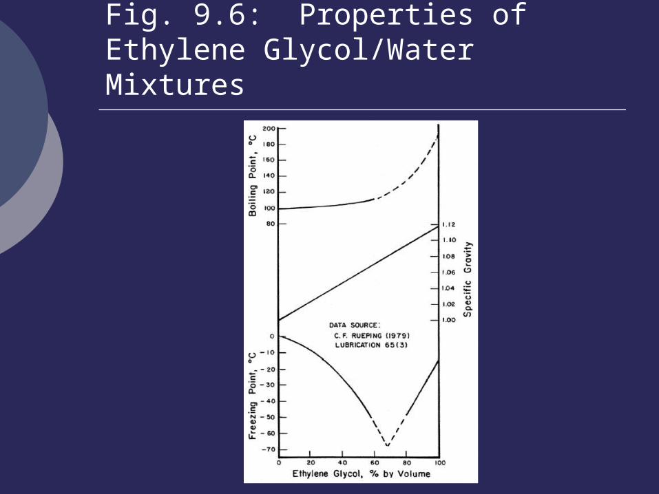
Fig. 9.6: Properties of Ethylene Glycol/Water Mixtures

Specific Heat of Coolant
The specific heat of ethylene glycol is,
For a 50/50 mix with water,
where Tw is temperature in C.
WW TC 0002892.0127.4
WW TC 003897.0409.3

Considerations
Ethylene glycol lowers the specific heat of the coolant, and this must be considered in the design of the cooling system.

Fig. 9.7: Engine Therrmostats
Thermostats
Bellows type with short sealed tube containing ether. Ether expands when heated causing the thermostat to open.
Bimetallic strip uncoils when heated causing the thermostat to open.

Fig. 9.8: Air-Cooled Engine

Comments
For these engines to cool properly a minimum of 0.04 m3/s of cooling air must be provided per brake kW of engine power.

Homework Set No. 8
Do the even problems at the end of Chapter 9 for next Tuesday.

NHRA diesel rail?
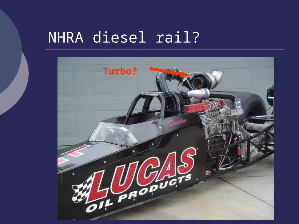
NHRA diesel rail?
Turbo?