chapter 9 detailing practices - maine.gov
TRANSCRIPT
CHAPTER 9 DETAILING PRACTICES Bridge Plan Development Guide
March 1, 2007 9-1
CHAPTER 9 DETAILING PRACTICES

CHAPTER 9 DETAILING PRACTICES Bridge Plan Development Guide
March 1, 2007 9-2
9.1 Table of Contents
CHAPTER 9 DETAILING PRACTICES............................................................................... 9-1
9.1 TABLE OF CONTENTS .................................................................................................... 9-2 9.2 FUNDAMENTALS ........................................................................................................... 9-4
9.2.1 Sheet Layout......................................................................................................... 9-4 9.2.2 Detail Layout ....................................................................................................... 9-4 9.2.3 Text....................................................................................................................... 9-4
9.2.3.1 Rules for Capitalization ................................................................................... 9-4 9.2.3.2 Abbreviations................................................................................................... 9-5
9.2.4 Dimensioning ....................................................................................................... 9-6 9.2.4.1 Referencing ...................................................................................................... 9-6 9.2.4.2 How and Where to Dimension......................................................................... 9-6 9.2.4.3 Stacking Dimensions ....................................................................................... 9-6 9.2.4.4 Organizing Dimensions ................................................................................... 9-7 9.2.4.5 Laying Out Curved Surfaces............................................................................ 9-7 9.2.4.6 Dimension Tolerances ..................................................................................... 9-7
9.3 PUTTING OUT MULTIPLE PROJECTS IN ONE PLAN SET.................................................. 9-8 9.4 COMBINING BRIDGE AND HIGHWAY DRAWINGS IN ONE PACKAGE .............................. 9-9
9.4.1 Duplication of Effort ............................................................................................ 9-9 9.4.2 Estimating Delineation ........................................................................................ 9-9
9.5 CHECKING................................................................................................................... 9-10 9.5.1 Introduction........................................................................................................ 9-10 9.5.2 Priority............................................................................................................... 9-10 9.5.3 Checking Lists.................................................................................................... 9-11
9.5.3.1 General........................................................................................................... 9-11 9.5.3.2 Checking a Title Sheet ................................................................................... 9-11 9.5.3.3 Checking Notes.............................................................................................. 9-11 9.5.3.4 Preliminary Plan............................................................................................. 9-12 9.5.3.5 General Plan................................................................................................... 9-12 9.5.3.6 Profile............................................................................................................. 9-12 9.5.3.7 Cross Sections................................................................................................ 9-12 9.5.3.8 Structural Details ........................................................................................... 9-13
9.5.4 Reinforcing Steel Schedule ................................................................................ 9-14 9.5.5 Estimate Check................................................................................................... 9-14 9.5.6 Check Repeated Information.............................................................................. 9-15 9.5.7 References for Detailing Standards ................................................................... 9-15
9.6 WELDING .................................................................................................................... 9-16 9.6.1 Introduction/Overview ....................................................................................... 9-16 9.6.2 Types of Joints.................................................................................................... 9-16 9.6.3 Fillet Welds ........................................................................................................ 9-16 9.6.4 Groove Welds..................................................................................................... 9-17
9.6.4.1 Overview........................................................................................................ 9-17 9.6.4.2 Complete versus Partial Penetration Groove Welds...................................... 9-18
9.6.5 Welding Symbols................................................................................................ 9-18
CHAPTER 9 DETAILING PRACTICES Bridge Plan Development Guide
March 1, 2007 9-3
9.6.6 Detail Practices ................................................................................................. 9-19 9.6.6.1 Fillet welds..................................................................................................... 9-19 9.6.6.2 Complete Joint Penetration Groove Welds.................................................... 9-19 9.6.6.3 Partial Joint Penetration Groove Welds......................................................... 9-19 9.6.6.4 Shop Welds and Field Welds......................................................................... 9-20
9.6.7 Example of Weld Symbols on Drawings ............................................................ 9-20 9.6.7.1 Welded Plate Girder....................................................................................... 9-20 9.6.7.2 Bridge Drain Standard Detail......................................................................... 9-21 9.6.7.3 Rail End Treatment ........................................................................................ 9-22

CHAPTER 9 DETAILING PRACTICES Bridge Plan Development Guide
March 1, 2007 9-4
9.2 Fundamentals
9.2.1 Sheet Layout
This section is reserved for a future discussion of the following:
1) Nesting details on a sheet/white space around details
2) Typical locations of plans, details, notes
3) Line up ortho views of same scale
9.2.2 Detail Layout
This section is reserved for a future discussion of the following:
1) White space around object
2) Offset of dimension lines and text
3) Housekeeping: parallel leader lines, aligned text
9.2.3 Text
9.2.3.1 Rules for Capitalization
A. Standard Sentence Capitalization
Standard capitalization applies to notes and annotations. Capitalize first letters of sentences and proper nouns.
B. All Caps
The information that is typically found in the middle of a title sheet (i.e. bridge name, waterway, town name etc...) and the conjunctions (i.e. “OVER” and “IN THE TOWN OF”) are all capitalized.
Detail titles shall be all capitalized and underlined. ABUTMENT NO. 1
Item descriptions and units on the Estimated Quantities Sheet may be in all capital letters.
It is preferable to have the items formatted with Title Formatting (upper and lower, each major word capitalized) but the MEDOT estimating software used to track items defaults to all uppercase letters and it is permissible to leave it that way.
C. Title Capitalization (Major Words Uppercase)
The first letter of each word in the name of a specific item description in a note shall be capitalized.
CHAPTER 9 DETAILING PRACTICES Bridge Plan Development Guide
March 1, 2007 9-5
Example: Erosion control mix may be substituted in those areas normally receiving loam and seed as directed by the Resident. Payment will be made under item 619.1401 Erosion Control Mix.
The first letters of the name of MEDOT specific documents shall be capitalized.
Example: Placement shall be in accordance with Standard Specification 619 Mulch.
D. Capitalization Exceptions
The following words should be capitalized as proper nouns when referring to a specific person on the project:
1) Contractor
2) Engineer
3) Resident
4) Bidders
5) Project Manager
The first letter in the word Contract shall be capitalized when referring this specific one.
Example: Payment shall be incidental to Contract items.
For guidance and examples of capitalization not covered here, refer to Standard Notes.
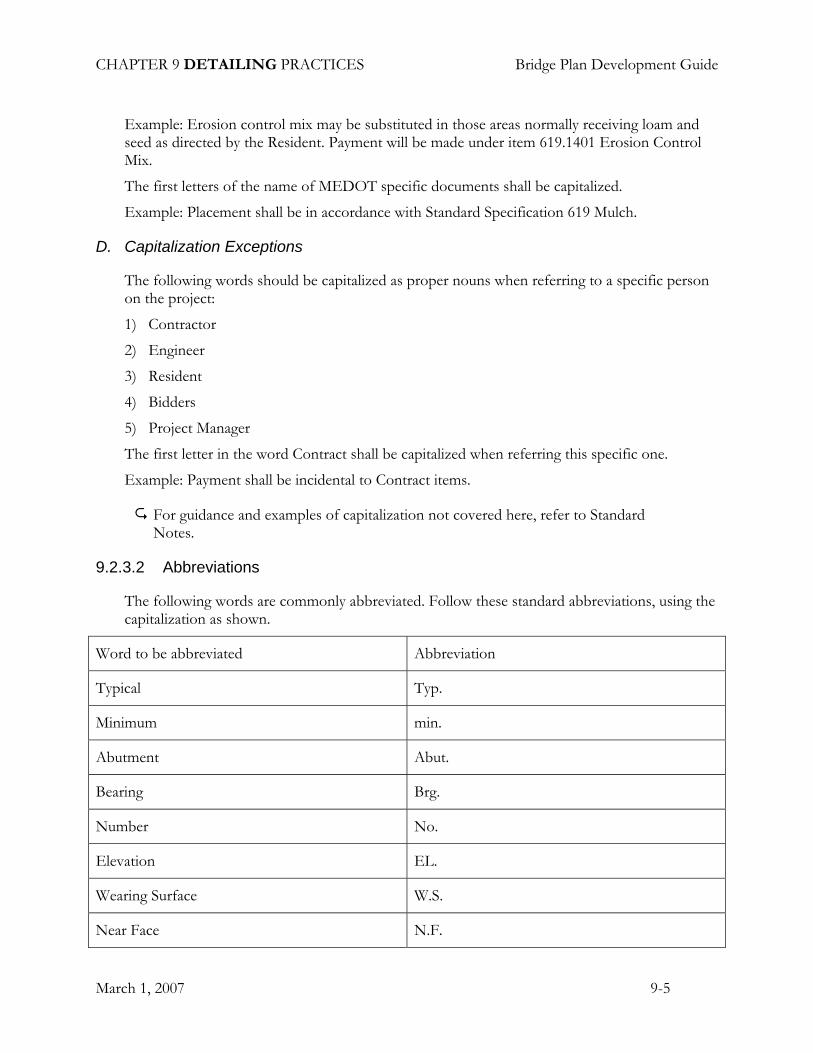
9.2.3.2 Abbreviations
The following words are commonly abbreviated. Follow these standard abbreviations, using the capitalization as shown.
Word to be abbreviated Abbreviation
Typical Typ.
Minimum min.
Abutment Abut.
Bearing Brg.
Number No.
Elevation EL.
Wearing Surface W.S.
Near Face N.F.

CHAPTER 9 DETAILING PRACTICES Bridge Plan Development Guide
March 1, 2007 9-6
Far Face F.F.
Each Face E.F.
Bottom Bot.
Equally Spaced eq. sp.
The following words may be abbreviated in certain uncommon circumstances. Use the following standard abbreviations, and capitalize as shown.
Concrete conc.
Structural struc.
Wearing Surface W.S.
Do not abbreviate the words Construction or Contraction, as their abbreviations may be confused during construction.
9.2.4 Dimensioning
9.2.4.1 Referencing
Dimensions should be referenced from the Centerline of Bearing, Centerline of Construction, or a reference line based upon these two lines.
If you are dimensioning to an existing structure, locate a point that has been surveyed well and that you are confident can be established in the field, such as a bridge seat or backwall. Check the location of the point by verifying it in reference to other lines and using the existing plans.
9.2.4.2 How and Where to Dimension
When dimensioning a concrete structure that will be formed, such as an abutment or a pier, the corners should be tied down from two directions. Generally this is done along and perpendicular to the structure, not along the skew.
Dimensions and labels should be kept outside of the object lines. This keeps the object in tact, the detail less cluttered, and clearer to understand.
Dimensions should not be repeated on the same or other details. Avoid dual dimensioning. An object with a given elevation should not be vertically dimensioned.
9.2.4.3 Stacking Dimensions
The line of dimensions closest to the object should be spaced ¾ inch away from the nearest object line. Sometimes they need to be further out, such as when you have annotation that you

CHAPTER 9 DETAILING PRACTICES Bridge Plan Development Guide
March 1, 2007 9-7
want to avoid crossing the dimension lines lines. The subsequent dimension lines should be stacked ½ inch apart.
9.2.4.4 Organizing Dimensions
The lines of dimensions should relate to each other if possible. Referenced points on a plan that are at the same elevation could be on the same line of dimensions. An example of this would be to dimension the base of a solid pier plan all on one line, and the top on another line. Another way would be to organize the dimension lines by placements of concrete. This could help to avoid the mistake of referencing to something that hasn’t been cast yet.
The dimensions should be organized so that the crossing of extension and dimension lines is kept to a minimum. This can be done by keeping the dimensions on the outside extents of the object furthest away from the object, and then work your way in. An example would be to keep the line of dimensions of the base of the solid pier further out than line for the top of it. If crossing lines become confusing to the eye, sometimes you can clear it up by deleting part of an extension line which a dimension line passes through. It is better to avoid deleting part of a dimension line or part of an object line. This practice of deleting parts of lines should be reserved for extenuating circumstances, and not used as a general rule of thumb.
Dimensions should not be repeated anywhere on the plans in any form, because this opens the door to errors if changes are made during the development of the plans and all of the repeats are not edited. When a vertical measurement is expressed with elevations the information should not be repeated with a dimension.
When dimensioning an object with two or more strings of dimensions, one should not close more than one dimension string because it opens the door to cumulative errors if all strings of dimensions do not total up to the same number.
9.2.4.5 Laying Out Curved Surfaces
Occasionally one is called upon to lay out a curved surface such as the curb on the superstructure plan of a curved bridge. This can be accomplished with offset dimensions to a straight reference line similar to the way a camber diagram is drawn. On curved surfaces at this scale, usually offsets at ten foot increments is sufficient.
9.2.4.6 Dimension Tolerances
Concrete should be dimensioned to the nearest one-quarter inch.
Structural steel should be dimensioned to the nearest one-sixteenth inch.
Camber Dimensions Should be given to one eighth inch
Blocking Elevations Should be within 0.02 feet.
Bridge seat elevations should be given to the nearest 0.01 feet
All other structural elevations should be given to the nearest 0.10 feet

CHAPTER 9 DETAILING PRACTICES Bridge Plan Development Guide
March 1, 2007 9-8
9.3 Putting Out Multiple Projects in One Plan Set
This section is reserved for a future discussion.

CHAPTER 9 DETAILING PRACTICES Bridge Plan Development Guide
March 1, 2007 9-9
9.4 Combining Bridge and Highway Drawings in One Package
This section is reserved for a future discussion of the following:
9.4.1 Duplication of Effort
9.4.2 Estimating Delineation

CHAPTER 9 DETAILING PRACTICES Bridge Plan Development Guide
March 1, 2007 9-10
9.5 Checking
9.5.1 Introduction
Sitting down to check a set of plans can be an overwhelming task because there are many different facets to consider. It is best to establish an organized approach so that one doesn’t overlook anything, or spend too much time on less important items. Every set of plans should be checked. It doesn’t have to take long, but it is a one of the most valuable blocks of time spent on a set of plans.
Please reference section 1-7 of the Bridge Design Guide for further information.
9.5.2 Priority
One needs to understand where it is most beneficial to focus their attention, to get the most value from a check. One way to do this is to ask yourself, “What is the risk to the cost and quality of the final product?” The effort should be directly proportional to the amount of effort spent checking that part of the plans.
Below is a list of things to consider in an order of priority to help you make decisions about where to focus the effort of checking. Numbers one thru four should be checked on every set of plans. Numbers five and six are important but are occasionally sacrificed or quickly reviewed due to schedule constraints. This list is not necessarily in the chronological order that they will be checked. Keep in mind that the focus of this list is toward a detailing check, and not a design check. Design correctness and safety should be addressed during the design check. It is assumed that while the project is being detailed, the plans are being periodically reviewed by the designer to assure that the basic concept and significant components are consistent with the design.
1. Is it constructible? a. Is it physically possible to construct it as shown? b. Is all the necessary information there so that it can be built? c. Are there any dimensions referencing things that don’t yet exist? d. Does the order of construction make sense?
2. Is the information (major dimensions, elevations, labeling etc.) correct? 3. Has the method of payment been established?
a. Is there a pay item or is it incidental to something else? b. Has payment been mistakenly indicated by more than one method?
4. Is the information complete and understandable to a person who is familiar with reading plans?
5. Do the details meet established industry and Bridge Program standards? 6. Are the spelling, grammar and capitalization correct?
Before beginning to check a set of plans one should be familiar with the special provisions and the history of the project and its issues.
CHAPTER 9 DETAILING PRACTICES Bridge Plan Development Guide
March 1, 2007 9-11
9.5.3 Checking Lists
Here are some lists of things to check and some common errors for use when checking plans. These are in no particular order.
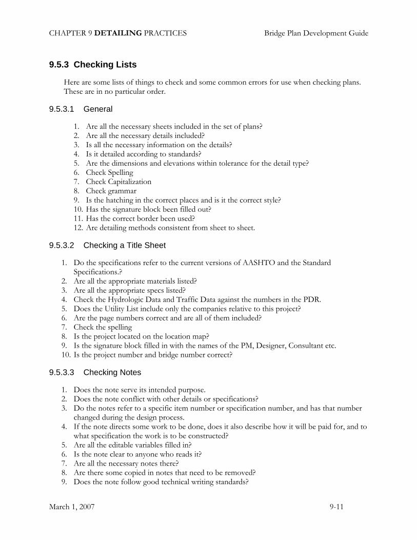
9.5.3.1 General
1. Are all the necessary sheets included in the set of plans? 2. Are all the necessary details included? 3. Is all the necessary information on the details? 4. Is it detailed according to standards? 5. Are the dimensions and elevations within tolerance for the detail type? 6. Check Spelling 7. Check Capitalization 8. Check grammar 9. Is the hatching in the correct places and is it the correct style? 10. Has the signature block been filled out? 11. Has the correct border been used? 12. Are detailing methods consistent from sheet to sheet.
9.5.3.2 Checking a Title Sheet
1. Do the specifications refer to the current versions of AASHTO and the Standard Specifications.?
2. Are all the appropriate materials listed? 3. Are all the appropriate specs listed? 4. Check the Hydrologic Data and Traffic Data against the numbers in the PDR. 5. Does the Utility List include only the companies relative to this project? 6. Are the page numbers correct and are all of them included? 7. Check the spelling 8. Is the project located on the location map? 9. Is the signature block filled in with the names of the PM, Designer, Consultant etc. 10. Is the project number and bridge number correct?
9.5.3.3 Checking Notes
1. Does the note serve its intended purpose. 2. Does the note conflict with other details or specifications? 3. Do the notes refer to a specific item number or specification number, and has that number
changed during the design process. 4. If the note directs some work to be done, does it also describe how it will be paid for, and to
what specification the work is to be constructed? 5. Are all the editable variables filled in? 6. Is the note clear to anyone who reads it? 7. Are all the necessary notes there? 8. Are there some copied in notes that need to be removed? 9. Does the note follow good technical writing standards?

CHAPTER 9 DETAILING PRACTICES Bridge Plan Development Guide
March 1, 2007 9-12
10. Do the references to the MaineDOT field representative say “Resident” as it should, or do they say “Construction Manager” or “Engineer”?
11. Is the spelling and capitalization correct?
9.5.3.4 Preliminary Plan
1. If the bridge has a superstructure, are the alignment curves off the bridge if possible, and is there at least a 1% grade across it for drainage?
2. Do the wing lengths and the fill around them look reasonable? 3. Are all the temporary and permanent impacts shown? 4. Are the property lines and clearing limits shown? 5. Are the contours shown? 6. Be sure to check the spelling because this will be seen at a public meeting.
9.5.3.5 General Plan
1. Has more than one alignment been developed, and if so is the correct one shown? 2. Is the horizontal curve data correct? 3. Have all the required details and levels been shown? (See Chapter 2) 4. Check the low points of the approaches for potential runoff and erosion problems. 5. Do the wing lengths agree with the structural plans? 6. Do the guardrail limits agree with the current structure, or have the structure/wings or
transition barrier changed since the Preliminary plan was developed thereby changing the guardrail limits?
7. Does the project length fall on even stations if possible? 8. Does the plan agree with the cross sections?
9.5.3.6 Profile
1. Are the vertical curves geometrically correct? Are the leg lengths equal? 2. Do the PVC and PVT fall on even stations if possible? 3. Is all the required information shown? (see Chapter 2) 4. Do the profile elevations agree with the cross section elevations? 5. Do the stations at centerline of bearing (if shown) agree with all the others shown on other
sheets?
9.5.3.7 Cross Sections
1. Do the elevations at centerline of bearing agree with the profile? 2. Do the cross sections agree with the plan? 3. Is all the required information show? 4. Check the superelevation. 5. Check the cross slopes of the travelway and shoulders. 6. Check the subgrade drainage. 7. Check the ditch elevations and flow.

CHAPTER 9 DETAILING PRACTICES Bridge Plan Development Guide
March 1, 2007 9-13
8. Do the guardrail limits agree with the current structure, or have the structure/wings or transition barrier changed since the Preliminary plan was developed thereby changing the guardrail limits? Do they agree with the general plan?
9.5.3.8 Structural Details
A. Cast in place Concrete Substructure
1. Check the geometric design of the structure to assure that such things as the wing lengths & elevations, and the bridge seat elevations are correctly designed.
2. Check the major dimensions and elevations for correctness. 3. Are all the necessary details shown? 4. Are all the necessary dimensions and information shown so that it is constructible? 5. Do any of the dimensions reference something that wouldn’t be constructed yet? 6. Is the station at the centerline of bearing correct? 7. Is the north arrow and flow arrow pointing in the correct direction? 8. Are the dimensions and reinforcing steel detailed using established standards? 9. Are the concrete joints shown and labeled correctly? 10. Are rebar splices needed at the construction joint locations? 11. Check the rebar splice lengths and embedment lengths.
B. Metal Plate Structures
1. Check the invert elevations 2. Check the barrel length 3. Check the Plate thickness 4. Check the end cut height 5. Check the weight 6. If it is an aluminum structure, does it have a top step or end reinforcement? 7.
C. Structures with Precast Slabs or Beams
1. Do the abutments need horizontal construction joints at the parapets and do they have them?
D. Cast in Place Superstructures
E. Structural Steel
1. Spot check some bottom of slab elevations
2. Check some dimensions on the Framing Plan
3. Check to see if beam splice bolts interfere with shear stud placement.
4. Are weld symbols drawn correctly?
5. Are the dimensions on plates and bar annotations in the correct order?
6. Are all necessary details shown?

CHAPTER 9 DETAILING PRACTICES Bridge Plan Development Guide
March 1, 2007 9-14
7. Is all necessary information shown on the details?
8. Are reference points and lines clear?
9. Do the bearing heights coo berate with the bridge seat heights?
10. If two beams with different dimensions are being spliced, do the filler plates add up correctly?
11. Check bolted connections for tool clearances.
F. Wearing Surface Rehabilitation
1. Is the thickness of the existing wearing surface different from the proposed, and if so do the drains and bridge joints need to be modified?
2. Do the approaches need to be transitioned up the new grade?
9.5.4 Reinforcing Steel Schedule
It is a good idea to talk to the designer or detailer to find out what changes or adjustments (if any) have been made to the geometrics of the structure during the design process, as this will give you a good idea of where to focus some of your checking. Some common adjustments are wings lengths and elevations, parapets, bridge seat elevations and footing elevations (especially if there is a seal).
1. Check to be sure that all the bars that are on the plans are also on the schedule. 2. Spot check the numbers of bars by counting them on some of the details. 3. If there are structures or parts that are exactly the same (such as two identical wings), with
the same bar designations, make sure that the total number of bars on the schedule reflects it.
4. Spot check the lengths of some of the bars. Be sure there is adequate length for splices, embedment, and variable/adjustable lengths and that the bar can stay within the concrete cover requirements. Checking the main reinforcing is the higher priority.
5. If there is an approach slab, check to see if the bars are in the schedule. 6. If there is a separate precast concrete reinforcing steel schedule within the plans, be sure to
check it.
9.5.5 Estimate Check
The estimate checker creates a simplified estimate that is done independently from the estimator. The focus of the effort should be on the big ticket items that represent the bulk of the cost of the project. Earth items don’t need to be calculated exactly. They should be simplified so that one can obtain a reasonable ball park number.
1. Does the estimate include all the necessary items? 2. Do the items numbers correlate with other notes or references on the plans and special
provisions? 3. Do the estimate sheets correlate with the estimate summary? 4. Does the Estimate Summary correlate with the Estimated Quantities Sheet?
CHAPTER 9 DETAILING PRACTICES Bridge Plan Development Guide
March 1, 2007 9-15
9.5.6 Check Repeated Information
Repetition of information on the plans should always be kept to a minimum due to the potential for inconsistencies, but there are some situations where repeated information is accepted practice.
In some instances, such as pay items, information simply needs to be cross referenced.
This list is intended to cross check this information which you may find repeated or cross referenced in the Plans and Special Provisions.
Check the centerline elevations on the profile against the centerline elevations on the cross sections.
If one has repeated the stations of the centerline bearings, or the centerline of the pipe on the Plan, Profile, structural drawings or anything else, then they must be cross checked.
Begin Transition, Begin Project etc. may be repeated on the Plan, Profile and Cross sections. These need to be cross checked.
Check the Title Sheet Index to see that all sheets have been indexed. Check to see if the numbers on the upper and lower right hand corners are correct and that the sheet names on the title sheet agree with the names on the individual sheets.
If specific pavement information has been given on the Typical Approach Section be sure that it is the same pavement, and the same thicknesses as is specified in the Pavement Specification.
Check through all the notes on the plans to be sure that any pay item referenced is actually in the Estimated Quantities.
Check all special provisions for pay items and be sure that they are included in your item lists.
Check that all the items on the Estimated Quantities Sheet are also in the Engineers Estimate. Then check to make sure that the summary sheet reflects all the Items that you have sheets for and that the quantities match each other.
9.5.7 References for Detailing Standards
Bridge Plan Development Guide
Bridge Design Guide (Chapter 1, Section 1-7)
AASHTO/NSBA Steel Bridge Collaboration Standards
CRSI Manual of Standard Practice

CHAPTER 9 DETAILING PRACTICES Bridge Plan Development Guide
March 1, 2007 9-16
9.6 Welding
9.6.1 Introduction/Overview
Welding is used in steel bridge construction in a variety of ways. It is used to fasten shear studs to beam flanges, pile tips to piles and bridge mounted rail posts to base plates. Built-up members ranging from bridge drains to plate girders can be created by welding individual plates and shapes together. Driving deep pile foundation wouldn’t be possible without splicing shorter sections of pile together with field welds.
The types of welds most frequently encountered in bridge construction are the fillet and groove welds.
In the design documents, weld type, size, length, location and special instructions are conveyed to the fabricator through weld symbols. Using symbols allows a wealth of information to be condensed into a small space on the drawings. Understanding weld symbols is easier with a little background on the types of welded joints and welds.
9.6.2 Types of Joints
The type of joint is determined by the configuration of the elements being connected. Five common joint types are the lap, butt, tee, corner and edge joints as shown in Figure 9-1.
Figure 9-1 Common Types of Welded Joints
9.6.3 Fillet Welds
Fillet welds are typically used on lap and tee joints. For example, welding cover plates to girder flanges and welded girder flange to web.

CHAPTER 9 DETAILING PRACTICES Bridge Plan Development Guide
March 1, 2007 9-17
Figure 9-2 Fillet Welds
9.6.4 Groove Welds
9.6.4.1 Overview
Groove welds are always used on butt joints where the connecting elements align in the same plane, i.e. splicing sections of H-pile together.
Groove welds require more precise fit up than fillet welds. Groove welds have specified minimum and maximum gaps or “root openings” between the plates to be connected for weld rod access. Thicker plates require larger root openings. Root openings can be reduced and weld rod access improved by beveling or shaping one or both of the plate edges. Groove welds are classified by the shape of the groove cut in the plate edge. Several common types of groove welds are shown in Figure 9-3.
Figure 9-3 Types of Groove Welds
Groove welds may also be used in tee, corner and edge joints.
CHAPTER 9 DETAILING PRACTICES Bridge Plan Development Guide
March 1, 2007 9-18
9.6.4.2 Complete versus Partial Penetration Groove Welds
When the depth of a groove weld extends through the entire thickness of the element it is called a complete joint penetration (CJP) groove weld. CJP groove welds are as strong as the elements being joined. When welds are required to develop the full strength of the member, such as when splicing lengths of H-pile together, CJP groove welds shall be specified.
When full member strength is not required, it is more economical to specify a partial joint penetration (PJP) groove weld. Partial penetration welds are used in the assembly of non-structural built-up components such as bridge drains.
9.6.5 Welding Symbols
The AASHTO LRFD and Standard Specifications state that welding symbols shall conform with the American Welding Society Publication A2.4, Symbols for Welding, Brazing and Nondestructive Examination. Refer to this document or the American Institute of Steel Construction’s Manual of Steel Construction, Allowable Stress Design, 9th Edition, page 4-155 for a listing and description of the standard weld symbols. These documents also describe the standard location of elements of a welding symbol.
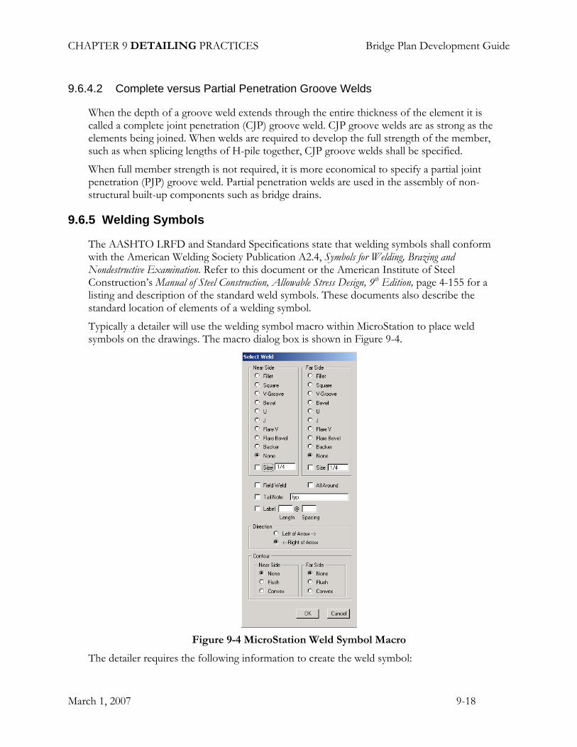
Typically a detailer will use the welding symbol macro within MicroStation to place weld symbols on the drawings. The macro dialog box is shown in Figure 9-4.
Figure 9-4 MicroStation Weld Symbol Macro
The detailer requires the following information to create the weld symbol:

CHAPTER 9 DETAILING PRACTICES Bridge Plan Development Guide
March 1, 2007 9-19
Type of weld
Weld on near side, far side or both
Weld size, if required (For more information on weld size, see Detailing Practices)
Shop weld or field weld
Weld all around or specific length
Special instructions to be included in tail note
For staggered welds, the length and centerline to centerline staggered spacing
Contour requirements such as ground flush or convex
9.6.6 Detail Practices
The following welding symbols detailing practices:
9.6.6.1 Fillet welds
Do not include a fillet weld size on the weld symbol unless the size is greater than the minimum specified in AASHTO LRFD and Standard Specifications. The minimum size of fillet welds is based on the base metal thickness of the thicker part joined.
9.6.6.2 Complete Joint Penetration Groove Welds
Use the following weld symbol without dimensions to designate a complete joint penetration weld:
Figure 9-5 Complete Joint Penetration Callout
This allows each fabrication shop to choose the CJP groove weld that best suits their shop practices resulting in more economical steel fabrication bids.
9.6.6.3 Partial Joint Penetration Groove Welds
Use the following weld symbol with dimensions above or below the arrow to designate a partial joint penetration weld:

CHAPTER 9 DETAILING PRACTICES Bridge Plan Development Guide
March 1, 2007 9-20
Figure 9-6 Partial Joint Penetration Callout
This allows each fabrication shop to choose the PJP groove weld that best suits their shop practices resulting in more economical steel fabrication bids.
9.6.6.4 Shop Welds and Field Welds
Clearly distinguish between shop and field welds.
Figure 9-7 Shop Weld vs. Field Weld
9.6.7 Example of Weld Symbols on Drawings
9.6.7.1 Welded Plate Girder
Figure 9-8 Welded Plate Girder Weld Example

CHAPTER 9 DETAILING PRACTICES Bridge Plan Development Guide
March 1, 2007 9-21
9.6.7.2 Bridge Drain Standard Detail
Figure 9-9 Bridge Drain Weld Example
CHAPTER 9 DETAILING PRACTICES Bridge Plan Development Guide
March 1, 2007 9-22
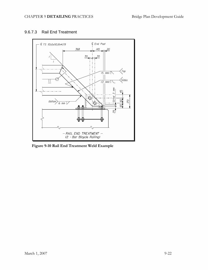
9.6.7.3 Rail End Treatment
Figure 9-10 Rail End Treatment Weld Example