chapter 7. culvert and bridge hydraulic design · drainage criteria manual bridge and culvert...
TRANSCRIPT
DRAINAGE CRITERIA MANUAL CULVERT AND BRIDGE HYDRAULIC DESIGN
City of Bella Vista, AR CB-i
CHAPTER 7. CULVERT AND BRIDGE HYDRAULIC DESIGN
CONTENTS
Section Page CB-
1.0 CULVERTS INTRODUCTION AND OVERVIEW ............................................................ 1 1.1 Required Design Information ........................................................................................... 1
1.1.1 Discharge ............................................................................................................... 2 1.1.2 Headwater .............................................................................................................. 2 1.1.3 Tailwater ................................................................................................................. 3 1.1.4 Outlet Velocity ........................................................................................................ 3
2.0 CULVERT HYDRAULICS ............................................................................................... 3 2.1 Key Hydraulic Principles .................................................................................................. 3
2.1.1 Energy and Hydraulic Grade Lines ........................................................................ 4 2.1.2 Culvert Flow Conditions ......................................................................................... 7
2.1.2.1 Inlet Control ........................................................................................ 7 2.1.2.2 Outlet Control ..................................................................................... 8
2.2 Energy Losses ................................................................................................................... 9 2.2.1 Inlet Losses .......................................................................................................... 10 2.2.2 Outlet Losses ....................................................................................................... 10 2.2.3 Friction Losses ..................................................................................................... 11
3.0 CULVERT SIZING AND DESIGN ................................................................................. 11 3.1 Determination of Design Flow Rate .............................................................................. 12
3.1.1 Design Frequency and Freeboard Criteria .......................................................... 12 3.2 Computer Applications .................................................................................................. 13 3.3 Design Considerations ................................................................................................... 13
3.3.1 Invert Elevations................................................................................................... 13 3.3.2 Culvert Shape, Size and Material ........................................................................ 13
3.4 Culvert Discharge Velocity ............................................................................................ 14 3.5 Minimum Slope ................................................................................................................ 15
4.0 CULVERT INLETS ........................................................................................................ 15 4.1 Projecting Inlets .............................................................................................................. 16
4.1.1 Corrugated Metal Pipe ......................................................................................... 17 4.1.2 Concrete Pipe ...................................................................................................... 17
4.2 Inlets with Headwalls ...................................................................................................... 18 4.2.1 Corrugated Metal Pipe ......................................................................................... 18 4.2.2 Concrete Pipe ...................................................................................................... 19 4.2.3 Wingwalls ............................................................................................................. 19 4.2.4 Aprons .................................................................................................................. 19
4.3 Special Inlets ................................................................................................................... 20 4.3.1 Corrugated Metal Pipe ......................................................................................... 21 4.3.2 Concrete Pipe ...................................................................................................... 21 4.3.3 Mitered Inlets ........................................................................................................ 21 4.3.4 Long Conduit Inlets .............................................................................................. 21 4.3.5 Improved Inlets..................................................................................................... 22
5.0 INLET PROTECTION .................................................................................................... 22 5.1 Debris Control ................................................................................................................. 22 5.2 Buoyancy ......................................................................................................................... 23
6.0 OUTLET PROTECTION ................................................................................................ 24 6.1 Scour ................................................................................................................................ 24
DRAINAGE CRITERIA MANUAL CULVERT AND BRIDGE HYDRAULIC DESIGN
CB-ii City of Bella Vista, AR
6.2 Energy Dissipation/Erosion Control ............................................................................. 24 6.2.1 Riprap as Outlet Protection .................................................................................. 25
6.2.1.1 Length of Protection ......................................................................... 25 6.2.1.2 Width of Protection ........................................................................... 25 6.2.1.3 Thickness and Stone Size/Gradation ............................................... 26 6.2.1.4 Multiple Culverts Outlets .................................................................. 28
6.2.2 Drop Structures .................................................................................................... 29 6.2.3 Flow Transition Mats ............................................................................................ 29
7.0 GENERAL CONSIDERATIONS .................................................................................... 30 7.1 Culvert Location .............................................................................................................. 30 7.2 Sedimentation ................................................................................................................. 31 7.3 Open Channel Inlets ....................................................................................................... 31 7.4 Transitions ....................................................................................................................... 32 7.5 Culvert Replacements .................................................................................................... 33 7.6 Fencing for Public Safety ............................................................................................... 33 7.7 Cover, Fill Heights and Bedding for Culverts .............................................................. 33
8.0 BRIDGES INTRODUCTION AND OVERVIEW ............................................................. 34 8.1 Coordination with Other Agencies ................................................................................ 35 8.2 Basic Criteria ................................................................................................................... 35
8.2.1 Design Approach.................................................................................................. 35 8.2.2 Bridge Opening Freeboard .................................................................................. 36
8.3 Hydraulic Analysis .......................................................................................................... 36 8.3.1 Backwater ............................................................................................................ 36 8.3.2 Expression for Backwater .................................................................................... 36 8.3.3 Backwater Coefficient .......................................................................................... 39 8.3.4 Effect of M and Abutment Shape (Base Curves) ................................................. 39 8.3.5 Effect of Piers (Normal Crossings)....................................................................... 41 8.3.6 Scour .................................................................................................................... 41
8.4 Design Procedure ........................................................................................................... 42 8.5 Inadequate Openings...................................................................................................... 43
9.0 REFERENCES .............................................................................................................. 45

DRAINAGE CRITERIA MANUAL CULVERT AND BRIDGE HYDRAULIC DESIGN
City of Bella Vista, AR CB-iii
TABLES
Table CB-1 Contract Coefficient 10 Table CB-2 Design Storm Frequencies and Minimum Freeboard 12 Table CB-3 Maximum Allowable Discharge Velocities 15 Table CB-4 Inlet Coefficients For Outlet Control 16 Table CB-5 Maximum Heights of Fill Over RCP Culverts 34 Table CB-6 Pipe Bedding Installation Types 34
FIGURES
Figure CB-1: Definition of Terms for Closed Conduit Flow ........................................................................... 6 Figure CB-2: Definition of Terms for Open Channel Flow ............................................................................ 6 Figure CB-3: Inlet Control - Unsubmerged Inlet............................................................................................ 7 Figure CB-4: Inlet Control - Submerged Inlet................................................................................................ 8 Figure CB-5: Outlet Control - Partially Full Conduit ...................................................................................... 9 Figure CB-6: Outlet Control - Full Conduit .................................................................................................... 9 Figure CB-7: Common Projecting Culvert Inlets ......................................................................................... 17 Figure CB-8: Inlet with Headwall and Wingwalls ........................................................................................ 18 Figure CB-9: Typical Headwall-Wingwall Configurations ........................................................................... 20 Figure CB-10: Configuration of Conduit Outlet Protection for Undefined Channel Downstream ............... 27 Figure CB-11: Culvert and Pipe Outlet Erosion Protection ......................................................................... 28 Figure CB-12: Guidance for Outlet Protection for Multiple Culverts ........................................................... 29 Figure CB-14: Subcritical Flow Transition ................................................................................................... 32 Figure CB-15: Normal Bridge Crossing Designation .................................................................................. 38 Figure CB-16: Base Curves for Wingwall Abutments ................................................................................. 40 Figure CB-17: Base Curves for Spill-through Abutments ........................................................................... 40 Figure CB-18: Incremental Backwater Coefficient for Pier ......................................................................... 44

DRAINAGE CRITERIA MANUAL CULVERT AND BRIDGE HYDRAULIC DESIGN
CB-iv City of Bella Vista, AR
THIS PAGE INTENTIONALLY LEFT BLANK

DRAINAGE CRITERIA MANUAL BRIDGE AND CULVERT HYDRAULIC DESIGN
City of Bella Vista, AR CB-1
1.0 CULVERTS INTRODUCTION AND OVERVIEW
The purpose of this chapter is to provide guidance for culvert and bridge hydraulic design. The primary
objective of a culvert or bridge is to convey stormwater flows, based on a design flow rate, through
embankments or under roadways without causing damage to adjacent properties and developments, the
roadway, or to the drainage structure. Specifically, this chapter provides information on the criteria and
methodology necessary to design culverts and bridges according to City requirements.
The function of a culvert is to convey surface water under a roadway, railroad, walking path, or other
embankment. In addition to the hydraulic function, the culvert must carry construction, highway, railroad,
or other traffic and earth loads. Therefore, culvert design involves both hydraulic and structural design
considerations. The hydraulic aspects of culvert design are set forth in this chapter.
Culverts are available in a variety of sizes, shapes, and materials. These factors, along with several
others, affect their capacity and overall performance. Sizes and shapes may vary from small circular
corrugated plastic pipes for driveways to large multiple side-by-side concrete box sections that can be
used in lieu of a bridge.
A careful approach to culvert design is essential, both in new land development and retrofit situations,
because culverts often significantly influence upstream and downstream flood risks, floodplain
management and public safety. Culverts can be designed to provide beneficial upstream and downstream
conditions and to simultaneously avoid creating a negative visual impact.
The information and references necessary to design culverts according to the procedure given in this
chapter can be found in FHWA’s Hydraulic Design Series, No. 5 (HDS-5 2005 -
http://isddc.dot.gov/.../FHWA), Hydraulic Design of Highway Culverts.
1.1 Required Design Information
The hydraulic design of a culvert consists of an analysis of the required performance of the culvert to
convey flow from one side of an embankment to the other. The designer must select a design flood
frequency, estimate the design discharge for that frequency, and set an allowable headwater elevation
based on the selected design flood and headwater considerations. These design criteria are dictated by
the City of Bella Vista. The culvert size and type can be selected after the design discharge, controlling
design headwater, slope, tailwater, and allowable outlet velocity have been determined.
The design of a culvert requires that the following be determined:
Impacts of various culvert sizes and dimensions on upstream and downstream flood risks,
including the implications of embankment overtopping.
How will the proposed culvert/embankment fit into the relevant major drainageway master plan?

CB-2 City of Bella Vista, AR
Are there multipurpose objectives that should be satisfied?
Alignment, grade, and length of culvert.
Size, type, end treatment, headwater, and outlet velocity.
Amount and type of cover.
Public safety issues, including the key question of whether or not to include a safety/debris rack.
Pipe material.
Need for protective measures against abrasion and corrosion.
Need for specially designed inlets or outlets.
Structural and geotechnical considerations, which are beyond the scope of this chapter.
1.1.1 Discharge
The discharge used in culvert design is usually estimated on the basis of a preselected storm recurrence
interval, and the culvert is designed to operate within acceptable limits of risk at that flow rate. The design
recurrence interval shall be based on the criteria set forth in Section 3.1.1 of this chapter. Peak discharge
rates for the design storm can be calculated using design methods described in Chapter 4 –
Determination of Stormwater Runoff.
1.1.2 Headwater
Culverts generally constrict the natural stream flow, which causes a rise in the upstream water surface.
The elevation of this water surface is termed headwater elevation, and the total flow depth in the stream
measured from the culvert inlet invert is termed headwater depth.
In selecting the design headwater elevation, the designer shall consider the following:
Roadway elevation above the structure and low point in roadway grade line.
Elevation at which water will flow to the next cross drainage.
Anticipated upstream and downstream flood risks for a range of return frequency events.
Potential damage to the culvert and the roadway caused by various headwater depths.
Traffic interruption caused by overtopping a roadway with flood flows.
Hazard to human life and safety caused by roadway or trail overtopping.
Headwater/Culvert Depth (HW/D) ratio.
Relationship to stability of embankment that culvert passes through.

DRAINAGE CRITERIA MANUAL BRIDGE AND CULVERT HYDRAULIC DESIGN
City of Bella Vista, AR CB-3
The headwater elevation for the design discharge shall be consistent with the freeboard and overtopping
criteria in Section 3.1.1 (table_cb1) of this chapter and Chapter 5 – Storm Sewer System Design. The
designer shall verify that the watershed divides are higher than the design headwater elevations. In flat
terrain, drainage divides are often undefined or nonexistent and culverts should be located and designed
for the least disruption of the existing flow distribution.
1.1.3 Tailwater
Tailwater is the flow depth in the downstream channel measured from the invert at the culvert outlet. It
can be an important factor in culvert hydraulic design because a submerged outlet may cause the culvert
to flow full rather than partially full, which affects the capacity of the culvert.
A field inspection of the downstream channel should be made to determine whether there are
obstructions that will influence the tailwater depth. Tailwater depth may be controlled by the stage in a
contributing stream, headwater from structures downstream of the culvert, reservoir water surface
elevations, or other downstream features.
1.1.4 Outlet Velocity
The outlet velocity of a culvert is the velocity measured at the downstream end of the culvert. The outlet
velocity is usually higher than the maximum natural stream velocity and can cause streambed scour and
bank erosion downstream from the culvert outlet. Permissible velocities at the outlet will depend upon
streambed characteristics and the type of energy dissipation (outlet protection) that is provided.
Variations in shape and size of a culvert seldom have a significant effect on the outlet velocity. Slope and
roughness of the culvert barrel are the principal factors affecting the outlet velocity.
2.0 CULVERT HYDRAULICS
This section describes key hydraulic principles that are pertinent to the design of culverts. Application of
these principles is presented in Section 3.0 of this chapter.
2.1 Key Hydraulic Principles
For purposes of the following review, it is assumed that the reader has a basic working knowledge of
hydraulics and is familiar with the Manning’s, continuity and energy equations, which are presented in
Chapter 7 – Open Channel Flow Design:

CB-4 City of Bella Vista, AR
2/13/249.1SAR
nQ (Equation CB-1)
where:
Q = Flow rate or discharge (ft3/sec)
n = Manning’s Roughness Coefficient
A = Flow Area (ft2)
R = Hydraulic Radius (ft)
S = Channel Slope (ft/ft)
2211 AvAvQ (Equation CB-2)
where:
Q = Flow rate or discharge (ft3/sec)
v = Velocity (ft/sec)
A = Flow Area (ft2)
losseszp
g
v
2
2
constant (Equation CB-3)
where:
v = Velocity (ft/sec)
g = Gravity (32.2 ft/sec2)
p = Pressure (lb/ft2)
γ = Specific weight of water (62.4 lb/ft3)
z = Height above datum (ft)
2.1.1 Energy and Hydraulic Grade Lines
Figures CB-1 and CB-2 illustrate the energy grade line (EGL) and hydraulic grade line (HGL) and related
terms.

DRAINAGE CRITERIA MANUAL BRIDGE AND CULVERT HYDRAULIC DESIGN
City of Bella Vista, AR CB-5
Energy Grade Line
The energy grade line, also known as the line of total head, is the sum of velocity head g
v
2
2
, the depth of
flow or pressure head
p, and the elevation above an arbitrary datum represented by the distance Z (see
Figure CB-1). The energy grade line slopes downward in the direction of flow by an amount equal to the
energy gradient HL/L, where HL equals the total energy loss over the distance L.
Hydraulic Grade Line
The hydraulic grade line is the sum of the elevation Z and the depth of flow or pressure head
p.
For open channel flow, the term
pis equivalent to the depth of flow and the hydraulic grade line is the
same as the water surface (see Figure CB-1). For pressure flow in closed conduits (e.g., culverts),
pis
the pressure head and the hydraulic grade line falls above the top of the conduit as long as the pressure
relative to atmospheric pressure is positive.

CB-6 City of Bella Vista, AR
Figure CB-1: Definition of Terms for Closed Conduit Flow (UDFCD USDCM 2001)
Figure CB-2: Definition of Terms for Open Channel Flow (UDFCD USDCM 2001)
Approaching the entrance to a culvert (refer to Point 1 of Figure CB-1) the flow is essentially uniform and
the hydraulic grade line and energy grade lines are almost the same. As water enters the culvert at the
inlet, the flow is first contracted and then expanded by the inlet geometry, which causes a loss of energy
at Point 2. As normal turbulent velocity distribution is reestablished downstream of the entrance at Point
3, a loss of energy is incurred through friction or from resistance. In short culverts, the entrance losses are

DRAINAGE CRITERIA MANUAL BRIDGE AND CULVERT HYDRAULIC DESIGN
City of Bella Vista, AR CB-7
likely to be high relative to the friction loss. At the exit, Point 4, an additional loss is incurred through
turbulence as the flow expands and is retarded by the water in the downstream channel. At Point 5 of
Figure CB-2 open channel flow is established and the hydraulic grade line is the same as the water
surface.
2.1.2 Culvert Flow Conditions
There are two major types of flow conditions in culverts: (1) inlet control and (2) outlet control. For each
type of control, a different combination of factors is used to determine the hydraulic capacity of a culvert.
The determination of actual flow conditions can be difficult; therefore, the designer must check for both
types of control and design for the most adverse condition. Inlet and outlet control are described in the
following sections.
2.1.2.1 Inlet Control
A culvert operates with inlet control when the flow capacity is controlled at the entrance by these factors:
Depth of headwater
Culvert cross-sectional area at inlet
Inlet edge configuration
Barrel shape
When a culvert operates under inlet control, headwater depth and the inlet edge configuration determine
the culvert capacity, with the culvert barrel usually flowing only partially full.
Inlet control for culverts may occur in two ways. The least common occurs when the headwater depth is
not sufficient to submerge the top of the culvert and, concurrently, the culvert invert slope is supercritical
as shown in Figure CB-3.
Figure CB-3: Inlet Control - Unsubmerged Inlet (UDFCD USDCM 2001)

CB-8 City of Bella Vista, AR
The most common occurrence of inlet control is when the headwater submerges the top of the culvert as
in Figure CB-4 below and the pipe does not flow full. A culvert flowing under inlet control is defined as a
hydraulically short culvert.
Figure CB-4: Inlet Control - Submerged Inlet (UDFCD USDCM 2001)
For a culvert operating with inlet control, the roughness, slope, and length of the culvert barrel and outlet
conditions (including tailwater) are not factors in determining culvert hydraulic performance.
2.1.2.2 Outlet Control
If the headwater is high enough and the culvert is sufficiently long and flat, the control will shift to the
outlet. In outlet control, the discharge is a function of the inlet losses, the headwater depth, the culvert
roughness, the culvert length, the barrel diameter, the culvert slope, and sometimes the tailwater
elevation.
In outlet control, culvert hydraulic performance is determined by these factors:
Depth of headwater
Culvert cross-sectional area
Inlet edge configuration
Culvert shape
Barrel slope
Barrel length
Barrel roughness
Depth of tailwater

DRAINAGE CRITERIA MANUAL BRIDGE AND CULVERT HYDRAULIC DESIGN
City of Bella Vista, AR CB-9
Outlet control will exist under two conditions: 1) the most common condition occurs when the culvert is
flowing full (Figure CB-6), and 2) the least common condition occurs where the headwater is insufficient
to submerge the top of the culvert and, concurrently, the culvert slope is subcritical (Figure CB-5). A
culvert flowing under outlet control is defined as a hydraulically long culvert.
Figure CB-5: Outlet Control - Partially Full Conduit (UDFCD USDCM 2001)
Figure CB-6: Outlet Control - Full Conduit (UDFCD USDCM 2001)
Culverts operating under outlet control may flow full or partly full depending on various combinations of
the factors described above. In outlet control, factors that may affect performance appreciably for a given
culvert size and headwater are barrel length and roughness, and tailwater depth.
2.2 Energy Losses
In short conduits, such as culverts, the losses caused by the entrance can be as important as the friction
losses through the conduit. The losses that must be evaluated to determine the carrying capacity of the
culverts consist of inlet (or entrance) losses, friction losses along the length of the culvert and outlet (or
exit) losses. These losses are described in Sections 2.2.1 through 2.2.3 of this chapter, respectively.
CB-10 City of Bella Vista, AR
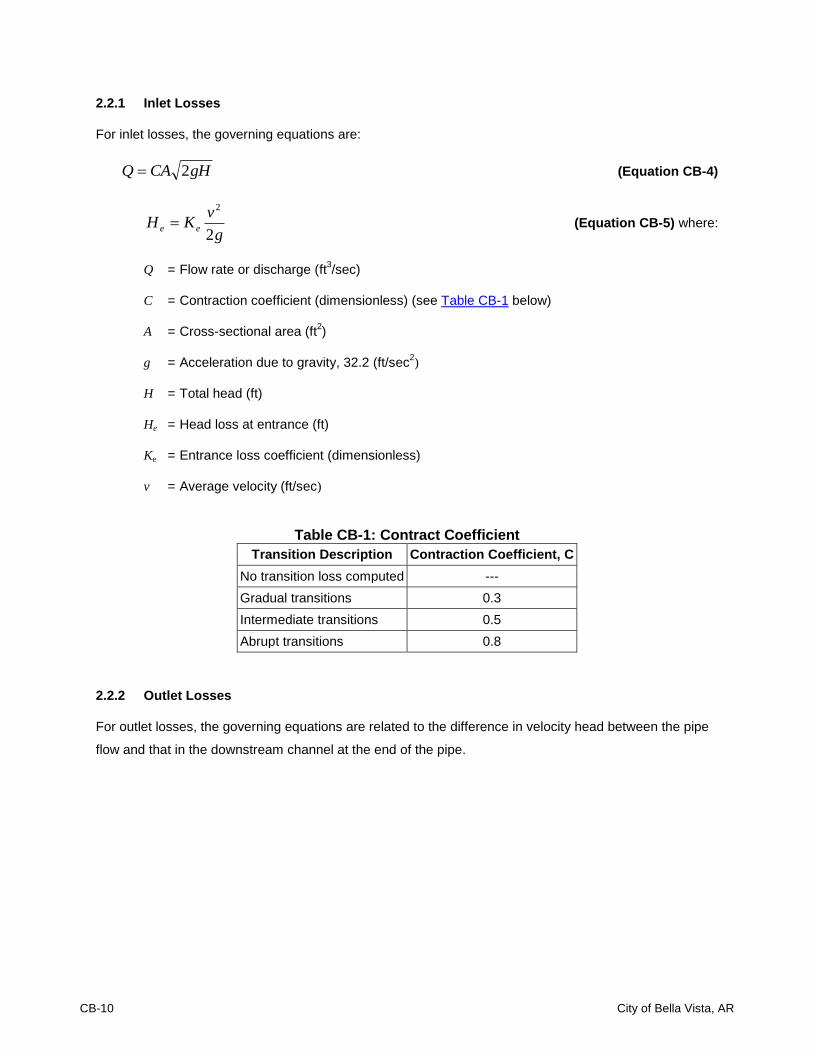
2.2.1 Inlet Losses
For inlet losses, the governing equations are:
gHCAQ 2 (Equation CB-4)
g
vKH ee
2
2
(Equation CB-5) where:
Q = Flow rate or discharge (ft3/sec)
C = Contraction coefficient (dimensionless) (see Table CB-1 below)
A = Cross-sectional area (ft2)
g = Acceleration due to gravity, 32.2 (ft/sec2)
H = Total head (ft)
He = Head loss at entrance (ft)
Ke = Entrance loss coefficient (dimensionless)
v = Average velocity (ft/sec)
Table CB-1: Contract Coefficient
Transition Description Contraction Coefficient, C
No transition loss computed ---
Gradual transitions 0.3
Intermediate transitions 0.5
Abrupt transitions 0.8
2.2.2 Outlet Losses
For outlet losses, the governing equations are related to the difference in velocity head between the pipe
flow and that in the downstream channel at the end of the pipe.

DRAINAGE CRITERIA MANUAL BRIDGE AND CULVERT HYDRAULIC DESIGN
City of Bella Vista, AR CB-11
2.2.3 Friction Losses
Friction head loss for turbulent flow in pipes flowing full can be determined from the Darcy-Weisbach
equation.
g
v
D
LfH f
2
2
(Equation CB-6)
where:
Hf = Frictional head loss (ft)
f = Friction factor (dimensionless)
L = Length of culvert (ft)
D = Hydraulic diameter of culvert (ft) (internal diameter for circular pipe)
v = Average velocity (ft/sec)
g = Acceleration due to gravity, 32.2 (ft/sec2)
The friction factor has been determined empirically and is dependent on relative roughness, velocity, and
barrel diameter. Moody diagrams can be used to determine the friction factor. The friction losses for
culverts are often expressed in terms of Manning’s n (see Chapter 5 – Storm Sewer System Design),
which is independent of the size of pipe and depth of flow. Another common formula for pipe flow is the
Hazen-Williams formula. Standard hydraulic texts should be consulted for the limitations of these
formulas.
3.0 CULVERT SIZING AND DESIGN
HDS-5 (FHWA 2005 - http://isddc.dot.gov/.../FHWA) provides valuable guidance for the design and
selection of drainage culverts. This particular circular explains inlet and outlet control and the procedure
for designing culverts. Culvert design is iterative and consists of the following steps:
1. Determine the flow rate of water the culvert must carry.
2. Select a culvert shape, type, and size with a particular inlet end treatment.
3. Determine a headwater depth from the relevant charts for both inlet and outlet control for the
design discharge, the grade and length of culvert, and the depth of water at the outlet (tailwater).

CB-12 City of Bella Vista, AR
4. Compare the largest depth of headwater (as determined from either inlet or outlet control) to the
design criteria. If the design criteria are not met, continue trying other culvert configurations until
one or more configurations are found to satisfy the design parameters.
5. Estimate the culvert outlet velocity and determine if there is a need for any special features such
as energy dissipators or armoring of the downstream channel.
These steps are described in Sections 3.1 through 3.5 of this chapter.
3.1 Determination of Design Flow Rate
The first step to consider in the hydraulic design of a culvert is the determination of the flow rate that the
culvert must convey. There is no single method for determining peak discharge that is applicable to all
watersheds. The method chosen should be a function of drainage area size, availability of data, and the
degree of accuracy desired.
The following methods described in Chapter 4 – Determination of Stormwater Runoff, shall be used to
generate peak discharge:
Rational Method – used for drainage areas less than 30 acres.
Soil Conservation Method – used for drainage areas between 30 and 2000 acres.
3.1.1 Design Frequency and Freeboard Criteria
The storm frequencies and freeboard used as the basis for culvert design are summarized in Table CB-2
below:
Table CB-2: Design Storm Frequencies and Minimum Freeboard
Description Design Storm
Frequency Minimum Freeboard
Trails 2 12 inches
Alley / Residential 10 12 inches
Sub-Collector / Collector 25 12 inches
Minor Arterial & Major Arterial 50 12 inches
Bridges (Alley/Residential & Collector Roadways) 50 12 inches *
Bridges (Arterial & Critical Service Access Roadways/Drives) 100 12 inches *
* from “Low Chord” / “Low Steel”

DRAINAGE CRITERIA MANUAL BRIDGE AND CULVERT HYDRAULIC DESIGN
City of Bella Vista, AR CB-13
3.2 Computer Applications
Although nomographs can still be used for design, the majority of engineers currently design culverts
using computer applications. Among these applications are the FHWA’s HY8 Culvert Analysis (Ginsberg
1987) and numerous proprietary applications such as CulvertMaster. FHWA’s HY8 Culvert Analysis
(Version 7.2) is located FHWA’s webpage (http://www.fhwa.dot.gov) for download.
3.3 Design Considerations
The actual design of a culvert installation is more complex than the simple process of sizing culverts
because of problems arising from topography and other considerations. Since the problems encountered
are too varied and too numerous to be generalized, the information in the design procedure presented
below is only a guide to design. Several combinations of entrance types, invert elevations, and pipe
diameters should be evaluated to determine the most economic design that will meet the conditions
imposed by topography and engineering. Descriptions of different variables that must be evaluated are
presented in Sections 3.3.1 through 3.3.2 of this chapter.
3.3.1 Invert Elevations
After determining the allowable headwater and tailwater elevations along with an approximate culvert
length, the culvert invert elevations must be assumed. To reduce the chance of failure due to scour,
invert elevations corresponding to the natural grade shall be used as a first trial.
For natural channels, the flow conditions in the channel upstream from the culvert should be investigated
to determine if scour will occur. For more information on scour, see Section 6.1 of this chapter.
3.3.2 Culvert Shape, Size and Material
After the invert elevations have been assumed, the shape of the culvert must be selected. The
permissible shapes of culverts under all roadways and embankments are square or rectangular box; or
circular, elliptical, or arch pipe.
Next, the diameter of pipe that will meet the headwater requirements should be determined. Because
small pipes are often plugged by sediment and debris, the minimum diameter of pipe for all culverts is 18-
inches or an equivalent (or larger) elliptical or arch pipe. The minimum square or rectangular box culvert
shall have a height of 18-inches and a width (“W”) designed to meet the loading (vehicular/overburden)
and hydraulic requirements for the desired application.

CB-14 City of Bella Vista, AR
The following outline provides guidelines for the appropriate use of various culvert shapes and materials.
Reinforced Concrete Pipe (RCP)
o Shall be used under all public roadways;
o RCP shall conform to AASHTO M170 for circular pipe and AASHTO M206 for arch pipe;
o All pipe having a diameter of 36-inches or greater must be RCP;
o When pipe cover is:
Less than 2-ft - RCP must meet ASTM Class IV specifications; and/or
2-foot or larger - RCP must meet ASTM Class III specifications
Reinforced Concrete Box (RCB)
o Shall be structurally designed to accommodate the earth and live loads to be imposed;
o Refer to the Arkansas State Highway and Transportation Department’s Reinforced Concrete
Box Culvert Standard Drawings; and
o Within public right of way, shall be capable of withstanding a minimum HL-93 loading.
Corrugated Metal Pipe (CMP) [including Smooth Lined (SLCMP)]
o Can only be used in areas outside of street right-of-way;
o Shall conform to AASHTO M36 and M218;
o Shall have minimum 2-foot cover; and
o Shall be properly bedded and backfilled with granular material.
Corrugated Polyethylene Pipe (CPP) [including Smooth Lined (SLCPP) such as HDPE]
o Can only be used in areas outside of street right-of-way;
o Shall conform to AASHTO M294, Type S specification; and
o Shall have minimum 2-foot cover; and
o Shall be properly bedded and backfilled with granular material.
3.4 Culvert Discharge Velocity
The outlet velocity must be checked to determine if significant scour will occur downstream during the
major storm. If scour is indicated (which is normally the case), refer to Section 6.0 of this chapter for
guidance on outlet protection. The maximum allowable discharge velocities from culverts for particular
downstream conditions are listed in Table CB-2:

DRAINAGE CRITERIA MANUAL BRIDGE AND CULVERT HYDRAULIC DESIGN
City of Bella Vista, AR CB-15
Table CB-3: Maximum Allowable Discharge Velocities
Downstream Condition Maximum Allowable Discharge Velocity
Grass 4 fps
Riprap 12 fps
Concrete 18 fps
Flow transition mat (or TRM) Manufacturer’s Specs.
3.5 Minimum Slope
To minimize sediment deposition in the culvert, the culvert slope must be equal to or exceed the slope
required for a minimum velocity of 3 fps when the pipe is flowing full as recommended in FHWA HEC-22.
The slope should be checked for each design. If the proper minimum velocity is not obtained, the pipe
diameter may be decreased; the slope steepened; a smoother pipe used, or a combination of these
measures implemented.
4.0 CULVERT INLETS
The capacity of culverts to convey water is limited by the capacity of the inlet. This is frequently
overlooked by designers. Culverts and open channels are often carefully designed with full consideration
given to slope, cross section, and hydraulic roughness, but without regard to the inlet limitations. Culvert
designs based on uniform flow equations rarely can convey their design capacity due to limitations
imposed by the inlet.
The design of a culvert (including the inlet and outlet) requires a balance between hydraulic efficiency;
purpose; and topography at the proposed culvert site. Where there is sufficient allowable headwater, the
choice of inlets may not be critical. When headwater depth is limited, erosion or sedimentation is more
likely to occur so a more efficient inlet will be required to obtain the necessary discharge capacity for the
culvert.
Although the primary purpose of a culvert is to convey flows, it may also be used to restrict flow. An
example of this is where the area upstream from the culvert is designed to be used for detention storage
so a reduced peak discharge rate is controlled by an inlet with limited capacity.
The inlet types described in this chapter may be selected to fulfill either of the above requirements
depending on the topography or conditions imposed by the designer. The entrance coefficient, Ke, as
defined for Equation CB-5, is a measure of the hydraulic efficiency at the inlet, with lower valves
indicating greater efficiency. Inlet coefficients are given in Table CB-3.
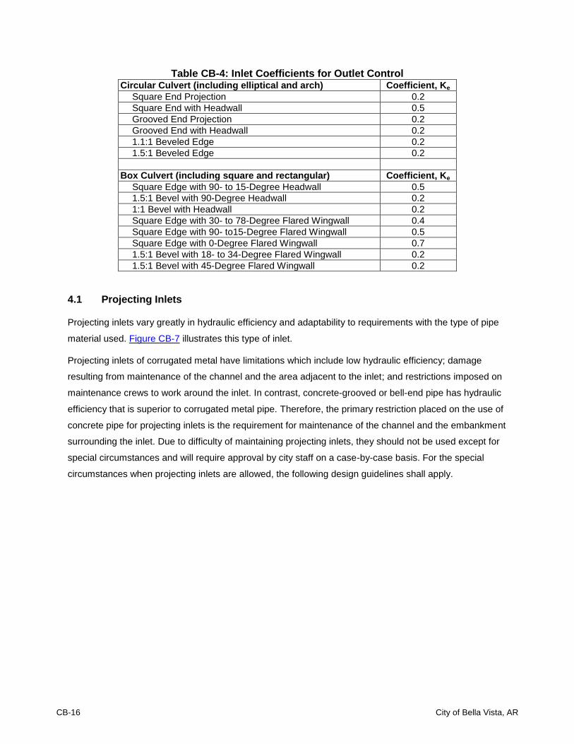
CB-16 City of Bella Vista, AR
Table CB-4: Inlet Coefficients for Outlet Control Circular Culvert (including elliptical and arch) Coefficient, Ke
Square End Projection 0.2
Square End with Headwall 0.5
Grooved End Projection 0.2
Grooved End with Headwall 0.2
1.1:1 Beveled Edge 0.2
1.5:1 Beveled Edge 0.2
Box Culvert (including square and rectangular) Coefficient, Ke
Square Edge with 90- to 15-Degree Headwall 0.5
1.5:1 Bevel with 90-Degree Headwall 0.2
1:1 Bevel with Headwall 0.2
Square Edge with 30- to 78-Degree Flared Wingwall 0.4
Square Edge with 90- to15-Degree Flared Wingwall 0.5
Square Edge with 0-Degree Flared Wingwall 0.7
1.5:1 Bevel with 18- to 34-Degree Flared Wingwall 0.2
1.5:1 Bevel with 45-Degree Flared Wingwall 0.2
4.1 Projecting Inlets
Projecting inlets vary greatly in hydraulic efficiency and adaptability to requirements with the type of pipe
material used. Figure CB-7 illustrates this type of inlet.
Projecting inlets of corrugated metal have limitations which include low hydraulic efficiency; damage
resulting from maintenance of the channel and the area adjacent to the inlet; and restrictions imposed on
maintenance crews to work around the inlet. In contrast, concrete-grooved or bell-end pipe has hydraulic
efficiency that is superior to corrugated metal pipe. Therefore, the primary restriction placed on the use of
concrete pipe for projecting inlets is the requirement for maintenance of the channel and the embankment
surrounding the inlet. Due to difficulty of maintaining projecting inlets, they should not be used except for
special circumstances and will require approval by city staff on a case-by-case basis. For the special
circumstances when projecting inlets are allowed, the following design guidelines shall apply.
DRAINAGE CRITERIA MANUAL BRIDGE AND CULVERT HYDRAULIC DESIGN
City of Bella Vista, AR CB-17
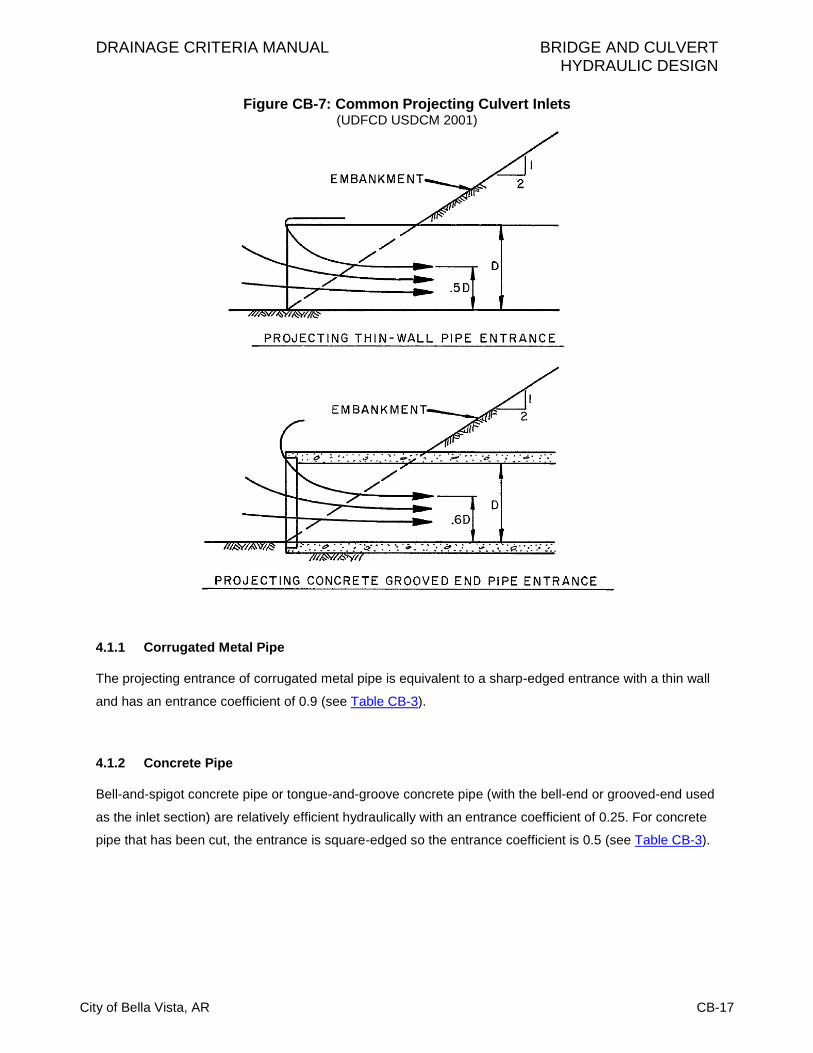
Figure CB-7: Common Projecting Culvert Inlets (UDFCD USDCM 2001)
4.1.1 Corrugated Metal Pipe
The projecting entrance of corrugated metal pipe is equivalent to a sharp-edged entrance with a thin wall
and has an entrance coefficient of 0.9 (see Table CB-3).
4.1.2 Concrete Pipe
Bell-and-spigot concrete pipe or tongue-and-groove concrete pipe (with the bell-end or grooved-end used
as the inlet section) are relatively efficient hydraulically with an entrance coefficient of 0.25. For concrete
pipe that has been cut, the entrance is square-edged so the entrance coefficient is 0.5 (see Table CB-3).
CB-18 City of Bella Vista, AR
4.2 Inlets with Headwalls
Headwalls may be used for a variety of reasons, including increasing the efficiency of the inlet; providing
embankment stability; and providing embankment protection against erosion. The relative efficiency of the
inlet varies with the pipe material used. The range of inlet coefficients for different headwall configurations
is summarized in Table CB-3. Different configurations of pipe with headwalls are described in Sections
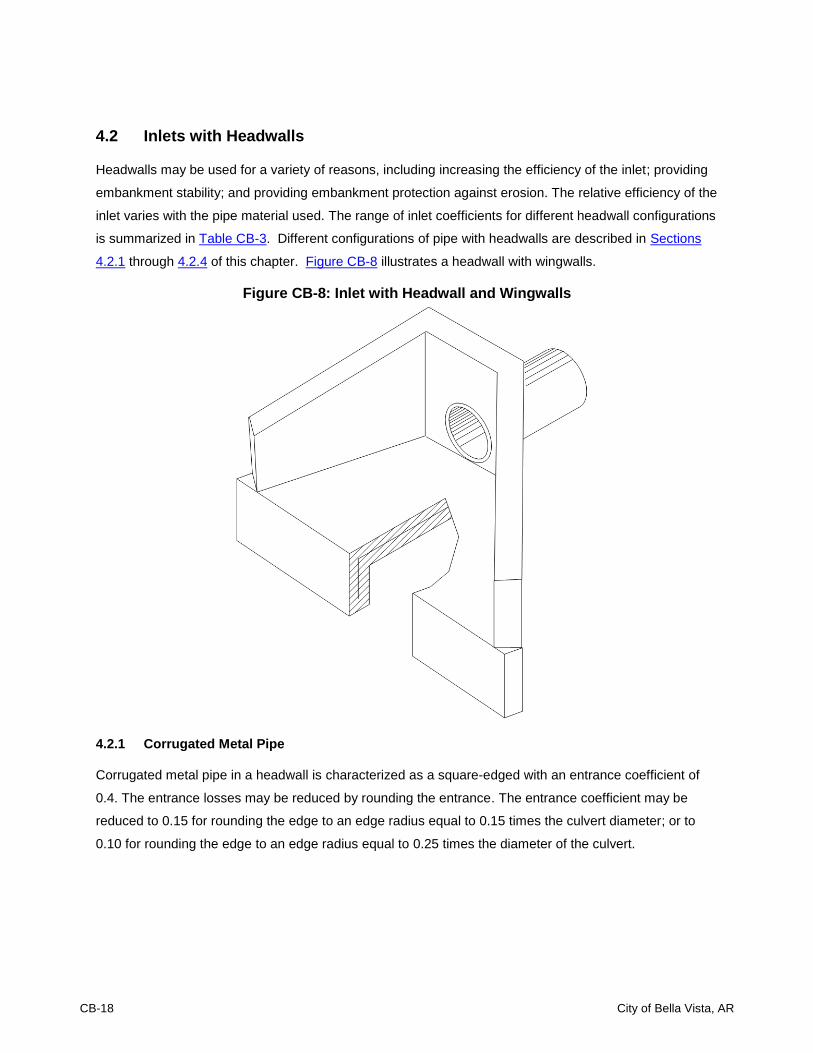
4.2.1 through 4.2.4 of this chapter. Figure CB-8 illustrates a headwall with wingwalls.
Figure CB-8: Inlet with Headwall and Wingwalls
4.2.1 Corrugated Metal Pipe
Corrugated metal pipe in a headwall is characterized as a square-edged with an entrance coefficient of
0.4. The entrance losses may be reduced by rounding the entrance. The entrance coefficient may be
reduced to 0.15 for rounding the edge to an edge radius equal to 0.15 times the culvert diameter; or to
0.10 for rounding the edge to an edge radius equal to 0.25 times the diameter of the culvert.

DRAINAGE CRITERIA MANUAL BRIDGE AND CULVERT HYDRAULIC DESIGN
City of Bella Vista, AR CB-19
4.2.2 Concrete Pipe
For tongue-and-groove or bell-end concrete pipe, there is little increase in hydraulic efficiency by adding a
headwall. The primary reason for using headwalls is for embankment protection and for ease of
maintenance. The entrance coefficient is equal to about 0.2 for a tongue-and-grooved and bell-end pipe.
The entrance coefficient is equal to 0.4 for concrete pipe that has been cut.
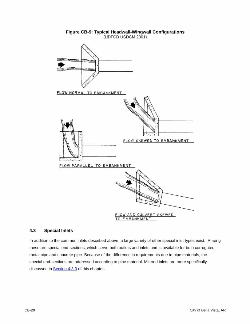
4.2.3 Wingwalls
Wingwalls are used where the side slopes of the channel adjacent are unstable or where the culvert is
skewed to the normal channel flow. Little increase in hydraulic efficiency is realized with the use of
wingwalls, regardless of the pipe material used. The use should be justified for reasons other than an
increase in hydraulic efficiency. Figure CB-9 illustrates several cases where wingwalls are used. For
parallel wingwalls, the minimum distance between wingwalls shall be at least 1.25 times the diameter of
the culvert pipe.
4.2.4 Aprons
If high headwater depths will exist or if the approach velocity of the channel will cause scour, a short
channel apron shall be provided at the toe of the headwall. The apron shall extend at least one pipe
diameter upstream from the entrance. Also the top of the apron shall not protrude above the normal
streambed elevation.
Culverts with wingwalls shall be designed with a concrete apron extending between the walls. Aprons
must be reinforced to control cracking. As illustrated in Figure CB-9, the actual configuration of the
wingwalls varies according to the direction of flow and will also vary according to the topographical
constraints of the site.
For conditions where scour may be a problem because of high approach velocities and/or the soil
conditions, a toe wall will also be required on the apron.
CB-20 City of Bella Vista, AR
Figure CB-9: Typical Headwall-Wingwall Configurations (UDFCD USDCM 2001)
4.3 Special Inlets
In addition to the common inlets described above, a large variety of other special inlet types exist. Among
these are special end-sections, which serve both outlets and inlets and is available for both corrugated
metal pipe and concrete pipe. Because of the difference in requirements due to pipe materials, the
special end-sections are addressed according to pipe material. Mitered inlets are more specifically
discussed in Section 4.3.3 of this chapter.

DRAINAGE CRITERIA MANUAL BRIDGE AND CULVERT HYDRAULIC DESIGN
City of Bella Vista, AR CB-21
4.3.1 Corrugated Metal Pipe
Special flared end-sections for corrugated metal pipe add little to the overall cost of the culvert and have
the following advantages:
1. Require less maintenance around the inlet;
2. Sustain less damage from maintenance work and from accidents compared to a projecting
entrance; and
3. Provide increased hydraulic efficiency.
4.3.2 Concrete Pipe
As in the case of corrugated metal pipe, special concrete flared-end sections (similar to flared-end
sections for corrugated metal pipe) may increase the embankment stability and retard erosion at the inlet.
They should be used where maintenance equipment must be used near the inlet or where, for aesthetic
reasons, a projecting entrance is considered too unsightly.
The hydraulic efficiency of a concrete flared-end section is dependent on the geometry of the end to be
used. Where the full contraction to the culvert diameter takes place at the first pipe section, the entrance
coefficient, Ke, is equal to 0.5. Where the full contraction to the culvert diameter takes place in the throat
of the end section, the entrance coefficient, Ke, is equal to 0.25.
4.3.3 Mitered Inlets
Mitered inlets are predominantly used with corrugated metal pipe and their hydraulic efficiency is
dependent on the construction procedure used. In practice if the embankment is not paved, the entrance
usually does not conform to the side slopes so results in a projecting entrance with Ke equal to 0.9. If the
embankment is paved, a sloping headwall is obtained with Ke equal to 0.60. Beveling the edges will result
in a Ke equal to 0.50.
Uplift is an important factor for mitered inlets. It is not good practice to use unpaved embankment slopes
where a mitered entrance may be submerged above the top of the pipe to an elevation one-half the
diameter of the culvert.
4.3.4 Long Conduit Inlets
Inlets are important in the design of culverts for road crossings and other short sections of conduit.
However, inlets are even more significant in the economical design of long culverts and pipes. Unused

CB-22 City of Bella Vista, AR
capacity in a long conduit will result in wasted investment. Long conduits are costly and require detailed
engineering, planning, and design work. The inlets to such conduits are extremely important to the
functioning of the conduit and must receive special attention.
Most long conduits require special inlet considerations to meet the particular hydraulic characteristics of
the conduit. Generally, on larger conduits, hydraulic model testing will result in better and less-costly inlet
construction.
4.3.5 Improved Inlets
Inlet edge configuration is one of the prime factors influencing the performance of a culvert operating
under inlet control. Inlet edges can cause a severe contraction of the flow, as in the case of a thin-edged
projecting inlet. In a flow contraction, the effective cross-sectional area of the barrel may be reduced to
approximately one-half of the actual available barrel area. As the inlet configuration is improved, the flow
contraction is reduced which improves the performance of the culvert.
A tapered inlet is a flared culvert inlet with an enlarged face section and a hydraulically efficient throat
section. Tapered inlets improve culvert performance by providing a more efficient control section (or
culvert throat). However, tapered inlets are not recommended for use on culverts flowing under outlet-
control situations because a simple beveled-edge inlet is of equal benefit. The two most common
improved inlets are the side-tapered inlet and the slope-tapered inlet. HDS-5 (FHWA 2005 -
http://isddc.dot.gov/.../FHWA) provides guidance on the design of improved inlets.
5.0 INLET PROTECTION
Inlets on culverts, especially on culverts to be installed in live streams, should be evaluated relative to
debris control and buoyancy. The following section discusses this further.
5.1 Debris Control
Accumulation of debris at a culvert inlet can result in the culvert not performing as designed. This can
result in damage caused by overtopping of the roadway and/or inundation of the upstream property.
Three main options exist to address the debris problem:
1. Retain the debris upstream of the culvert;
2. Attempt to pass the debris through the culvert; or
3. Install a bridge.
If the debris is to be retained by an upstream structure or at the culvert inlet, frequent maintenance may

DRAINAGE CRITERIA MANUAL BRIDGE AND CULVERT HYDRAULIC DESIGN
City of Bella Vista, AR CB-23
be required. The design of a debris control structure shall include a thorough study of the debris problem.
Factors to be considered in a debris study include the following:
Type of debris;
Quantity of debris;
Expected changes in type and quantity of debris due to future land use;
Stream flow velocity in the vicinity of culvert entrance;
Maintenance access requirements;
Availability of storage;
Maintenance plan for debris removal; and
Assessment of damage due to debris clogging, if protection is not provided.
FHWA’s Hydraulic Engineering Circular, No. 9 (HEC-9 2005 - http://www.fhwa.dot.gov/engineering/),
Debris Control Structures, shall be referenced when designing debris control structures.
5.2 Buoyancy
When a culvert is functioning with inlet control, an air pocket will form just inside the inlet. As a result a
buoyant effect is created once the inlet is submerged. The buoyancy forces increase as the headwater
depth increase. These forces, along with vortexes and eddy currents, can cause scour; undermine culvert
inlets; and erode embankment slopes. This makes the inlet vulnerable to failure, especially with deep
headwater.
The large unequal pressures resulting from inlet constriction are accentuated when the capacity of the
culvert is impaired by debris or damage. These pressures are essentially buoyancy forces that can cause
entrance failures - particularly on corrugated metal pipe with mitered; skewed; or projecting ends. The
failure potential of the pipe will increase with steepness of the culvert slope; depth of the potential
headwater; flatness of the fill slope over the upstream end of the culvert; and the depth of the fill over the
pipe.
Anchorage at the culvert entrance helps to protect against these failures by increasing the dead load on
the end of the culvert; protecting against bending damage; and by protecting the fill slope from the
scouring action of the flow. When inlet control conditions are present, a standard concrete headwall or
endwall will be required (unless otherwise approved by the City) to counteract the hydrostatic uplift and to
prevent failure due to buoyancy.
A combination of high head on the outside of the inlet and the large region of low pressure on the inside
of the inlet due to separation can lead to a large bending moment being exerted on the end of the culvert,
which may result in failure. This problem has been noted in the case of culverts under high fills; on steep

CB-24 City of Bella Vista, AR
slopes; and with projecting inlets. In cases where upstream detention storage requires headwater depth
in excess of 20 feet, reducing the culvert size is required to limit the discharge rate rather than using an
inefficient projecting inlet.
6.0 OUTLET PROTECTION
Scour at culvert outlets is a common occurrence and must be accounted for. The natural channel flow is
usually confined to a lesser width and greater depth as it passes through a culvert barrel. Increased flow
velocity typically results with potentially erosive capabilities as it exits the barrel. Turbulence and erosive
eddies form as the flow expands to conform to the natural channel. However, the velocity and depth of
flow at the culvert outlet and the velocity distribution upon reentering the natural channel are not the only
factors that need consideration. Other factors to consider with respect to scour potential include the
characteristics of the channel bed and bank material; velocity; depth of flow in the channel at the culvert
outlet; and the amount of sediment and other debris conveyed in the flow. Due to the variation in
expected flows and the difficulty in evaluating the variables described above, scour prediction is an
inexact science.
6.1 Scour
Protection against scour at culvert outlets varies from limited riprap placement to complex and expensive
energy dissipation devices. At some locations, use of a rougher culvert material may alleviate the need
for a special outlet protection device. Pre-formed scour holes (approximating the configuration of naturally
formed holes) dissipate energy while providing a protective lining to the streambed. Methods for locating
and predicting scour hole dimensions are provided in FHWA’s Hydraulic Engineering Circular, No. 14
(HEC-14 , 2006), Hydraulic Design of Energy Dissipators for Culverts and Channels.
6.2 Energy Dissipation/Erosion Control
Riprap-armored channel expansions and concrete aprons can protect the channel while redistributing or
spreading its flow. Barrel-outlet expansions operate in a similar manner. Headwalls and cutoff walls
protect the integrity of the fill. When outlet velocities are high enough to create excessive downstream
problems, consideration should be given to more complex energy dissipation devices. Design information
for the general types of energy dissipators can be found in HEC-14 (2006).
Three forms of energy dissipators and erosion control are approved by the City of Bella Vista: Riprap
(requiring City approval), Drop Structures and Flow Transition Mats.
DRAINAGE CRITERIA MANUAL BRIDGE AND CULVERT HYDRAULIC DESIGN
City of Bella Vista, AR CB-25
6.2.1 Riprap as Outlet Protection
Riprap is generally an effective measure for erosion and scour protection, but is a nuisance to maintain
and an eyesore to the public. Information regarding the sizing of riprap is provided in Chapter 7 – Open
Channel Flow Design. Riprap can only be used with City approval and must be grouted in place. Riprap
shall not be the first choice for energy dissipation/erosion control. City approval will be dependent upon
the design engineer showing the ineffectiveness of other types of energy dissipation devices for the
specific situation under consideration. The following sections shall be used in the design of riprap as
outlet protection. In all cases the thickness/structural layer of riprap as outlet protection shall be
constructed as shown in Figure CB-11.
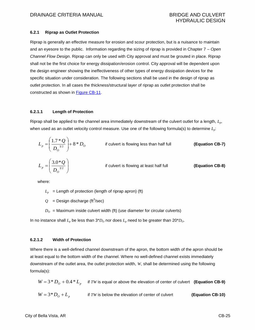
6.2.1.1 Length of Protection
Riprap shall be applied to the channel area immediately downstream of the culvert outlet for a length, Lp,
when used as an outlet velocity control measure. Use one of the following formula(s) to determine Lp:
O
O
p DD
QL *8
*7.123
if culvert is flowing less than half full (Equation CB-7)
23
*0.3
O
pD
QL if culvert is flowing at least half full (Equation CB-8)
where:
Lp = Length of protection (length of riprap apron) (ft)
Q = Design discharge (ft3/sec)
DO = Maximum inside culvert width (ft) (use diameter for circular culverts)
In no instance shall Lp be less than 3*DO nor does Lp need to be greater than 20*DO.
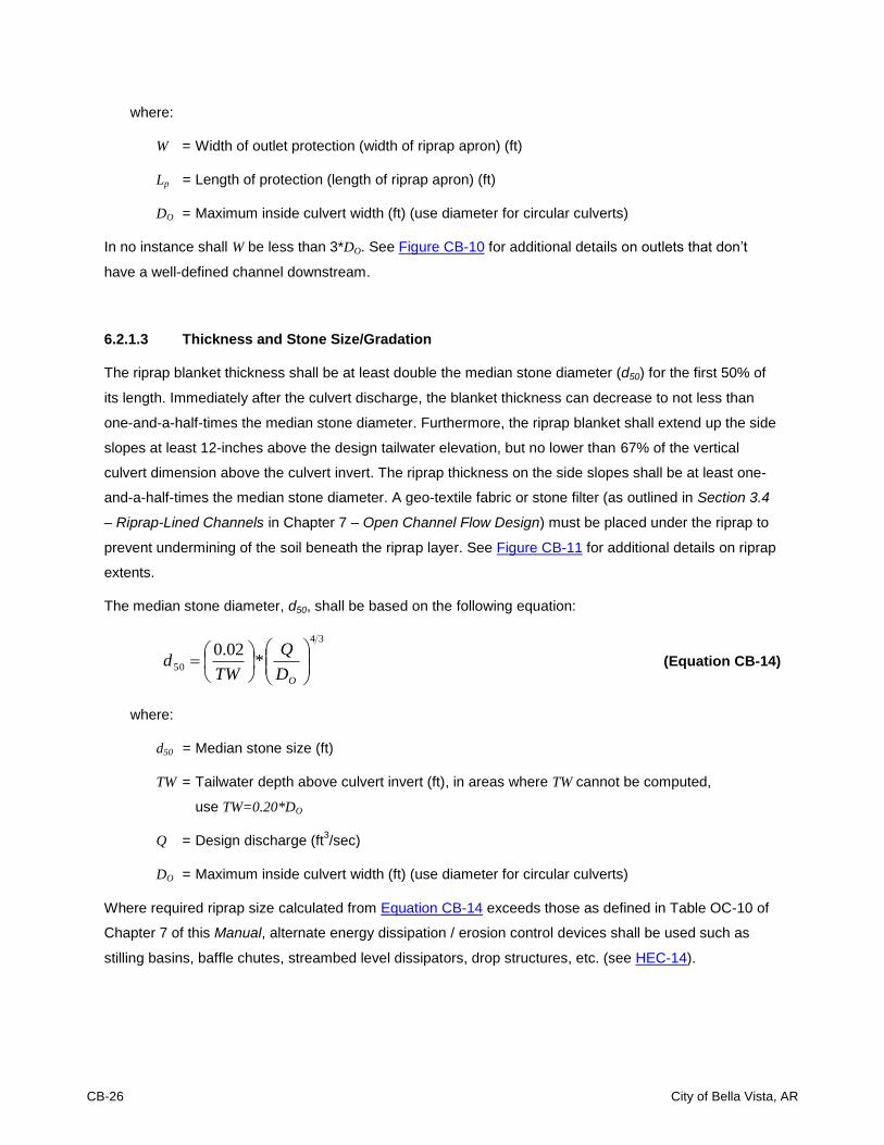
6.2.1.2 Width of Protection
Where there is a well-defined channel downstream of the apron, the bottom width of the apron should be
at least equal to the bottom width of the channel. Where no well-defined channel exists immediately
downstream of the outlet area, the outlet protection width, W, shall be determined using the following
formula(s):
pO LDW *4.0*3 if TW is equal or above the elevation of center of culvert (Equation CB-9)
pO LDW *3 if TW is below the elevation of center of culvert (Equation CB-10)
CB-26 City of Bella Vista, AR
where:
W = Width of outlet protection (width of riprap apron) (ft)
Lp = Length of protection (length of riprap apron) (ft)
DO = Maximum inside culvert width (ft) (use diameter for circular culverts)
In no instance shall W be less than 3*DO. See Figure CB-10 for additional details on outlets that don’t
have a well-defined channel downstream.
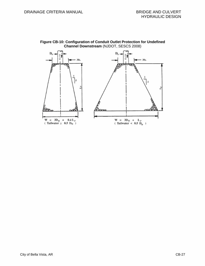
6.2.1.3 Thickness and Stone Size/Gradation
The riprap blanket thickness shall be at least double the median stone diameter (d50) for the first 50% of
its length. Immediately after the culvert discharge, the blanket thickness can decrease to not less than
one-and-a-half-times the median stone diameter. Furthermore, the riprap blanket shall extend up the side
slopes at least 12-inches above the design tailwater elevation, but no lower than 67% of the vertical
culvert dimension above the culvert invert. The riprap thickness on the side slopes shall be at least one-
and-a-half-times the median stone diameter. A geo-textile fabric or stone filter (as outlined in Section 3.4
– Riprap-Lined Channels in Chapter 7 – Open Channel Flow Design) must be placed under the riprap to
prevent undermining of the soil beneath the riprap layer. See Figure CB-11 for additional details on riprap
extents.
The median stone diameter, d50, shall be based on the following equation:
34
50 *02.0
OD
Q
TWd (Equation CB-14)
where:
d50 = Median stone size (ft)
TW = Tailwater depth above culvert invert (ft), in areas where TW cannot be computed,
use TW=0.20*DO
Q = Design discharge (ft3/sec)
DO = Maximum inside culvert width (ft) (use diameter for circular culverts)
Where required riprap size calculated from Equation CB-14 exceeds those as defined in Table OC-10 of
Chapter 7 of this Manual, alternate energy dissipation / erosion control devices shall be used such as
stilling basins, baffle chutes, streambed level dissipators, drop structures, etc. (see HEC-14).
DRAINAGE CRITERIA MANUAL BRIDGE AND CULVERT HYDRAULIC DESIGN
City of Bella Vista, AR CB-27
Figure CB-10: Configuration of Conduit Outlet Protection for Undefined Channel Downstream (NJDOT, SESCS 2008)
CB-28 City of Bella Vista, AR
Figure CB-11: Culvert and Pipe Outlet Erosion Protection (UDFCD USDCM 2002)
Notes: 1. Headwall with wingwalls or flared-end section required at all culvert outlets. 2. Cutoff wall required at end of wingwall aprons and end sections. Minimum depth of cutoff wall equals 2 times d50
or 3-feet, whichever is deeper. 3. Provide joint fasteners for flared-end sections.
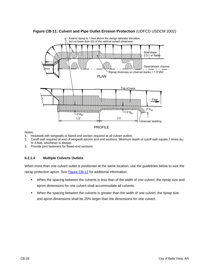
6.2.1.4 Multiple Culverts Outlets
When more than one culvert outlet is positioned at the same location, use the guidelines below to size the
riprap protection apron. See Figure CB-12 for additional information.
When the spacing between the culverts is less than of the width of one culvert, the riprap size and
apron dimensions for one culvert shall accommodate all culverts.
When the spacing between the culverts is greater than the width of one culvert, the riprap size
and apron dimensions shall be 25% larger than the dimensions for one culvert.

DRAINAGE CRITERIA MANUAL BRIDGE AND CULVERT HYDRAULIC DESIGN
City of Bella Vista, AR CB-29
Figure CB-12: Guidance for Outlet Protection for Multiple Culverts (NJDOT, SESCS 2008)
All Culverts Same Diameter Discharging Same Q
For S less than 25% W0, size the riprap & length for one pipe; Width shall accommodate all culverts. For S equal or more than 25% W0, size the riprap & length for one pipe; Increase values by 25%.
6.2.2 Drop Structures
Drop structures are commonly used for flow control and energy dissipation. Changing the channel slope
from steep to mild and/or by placing drop structures at intervals along the channel reach can change a
continuous steep slope into a series of gentle slopes and vertical drops. By slowing down and
transferring high velocities to prevent erosion, drop structures control the slope of the channel to prevent
erosion from developing. The kinetic energy or velocity gained by the water as it drops over the crest of
each structure is dissipated by a specially designed apron or stilling basin. HEC-14 (FHWA 2006)
provides guidance for the design and selection of drop structures.
6.2.3 Flow Transition Mats
A flow transition mat (FTM) is a long-term non-biodegradable bio-technical alternative for hard armor such
as riprap. It is usually a mechanically-anchored matting designed with voids throughout the structure to
enable vegetative growth and cover the material while also providing mechanical protection in areas
where design discharges exert velocities and shear stresses that exceed the limits of natural vegetation.
FTMs are used to extend the performance limits of natural vegetation by retaining soil particles and
vegetative seeds; promoting conditions for accelerated vegetative growth; and reinforcing the vegetative
cover. The EPA has documented FTMs as useful BMPs for stormwater runoff. The EPA’s Storm Water
Technology Fact Sheet for FTMs can be found at http://www.epa.gov/owm/mtb/turfrein.pdf and provides a
useful general discussion on the benefits; specific locations for use; and other general information.
Many different manufacturers produce FTMs, each with its own patented methods and material
combinations. Some of the manufacturers/distributors of FTMs include North American Green, Propex,
ScourStop, Tensar, and many others. FTMs shall be selected, designed, and installed according to the

CB-30 City of Bella Vista, AR
manufacturer’s recommendation. When attempting to implement such reinforcement into the design of
energy dissipation/erosion control, it will be the responsibility of the design engineer to provide the City
with appropriate material specifications and design information. Enough information needs to be provided
to ensure the product selected and specified in a design shows that it is adequately suited for the
situation in the field.
Figure CB-13: Typical Flow Transition Mat Application (Scourstop.com)
7.0 GENERAL CONSIDERATIONS
7.1 Culvert Location
Culvert location is an integral part of the total design. The main purpose of a culvert is to convey drainage
expeditiously and effectively. For possible culvert locations, the designer should identify all live stream
crossings; springs; low areas; gullies; and impoundment areas created by new embankments and/or
excavations. Note that environmental permitting constraints will often apply for new culverts or retrofits,
such as a Section 404 permit that regulates construction activities in jurisdictional wetlands and “Waters
of the United States.”
Culverts shall be located on existing stream alignments and aligned to give the stream a direct entrance
and a direct exit. Abrupt changes in direction at either end may retard the flow and make a larger
structure necessary. If necessary, a direct inlet and outlet may be obtained by means of a channel
change; skewing the culvert; or a combination of these. The choice of alignment should be based on
environmental concerns; hydraulic performance; and/or maintenance considerations.

DRAINAGE CRITERIA MANUAL BRIDGE AND CULVERT HYDRAULIC DESIGN
City of Bella Vista, AR CB-31
If possible, a culvert shall have the same alignment as its channel. Often this is not practical and where
the water must be turned into the culvert, headwalls, wingwalls, and aprons with configurations similar to
those in Figure CB-9 shall be used as protection against scour and to provide an efficient inlet.
7.2 Sedimentation
Deposits usually occur within the culvert when velocities are smaller than the design flow. The deposits
may be removed during larger storms when it has the relative transport capacity of flow in the stream and
in the culvert. Removal will also be dependent on the compaction and composition of the deposits; flow
duration; pond depth above the culvert; and other factors.
Culvert location in both plan and profile is of particular importance to the maintenance of sediment-free
culverts. Deposits most often occur in culverts when the sediment transport capacity of the flow in the
culvert is often less than in the stream.
Deposits in culverts may also occur because of the following conditions:
At moderate flow rates the culvert cross section is larger than that of the stream, so the flow
depth and sediment transport capacity is reduced within the culvert compared to the stream.
Point bars form on the inside of stream bends. Culvert inlets placed at bends in the stream will be
subject to deposition in the same manner. This effect is most pronounced in multiple-barrel
culverts with the barrel on the inside of the curve often becoming almost totally plugged with
sediment deposits.
Abrupt changes to a flatter grade in the culvert or in the channel adjacent to the culvert will induce
sedimentation. Gravel and cobble deposits are common downstream from the break in grade
because of the reduced transport capacity in the flatter section.
7.3 Open Channel Inlets
Entrances to open channels often require the same careful planning and design as is needed for culverts
and long conduits if the necessary hydraulic balance is to be achieved. The energy grade line shall be
analyzed by the designer to provide proper balanced energy conversion; velocity control; energy loss;
and other factors that control the downstream flow. Channel confluences in particular require careful
hydraulic design to eliminate scour; reduce oscillating waves; and minimize upstream backwater effects.

CB-32 City of Bella Vista, AR
7.4 Transitions
Concepts of conservation of energy and open channel hydraulics must be included in the design when
transitioning from pipe flow to open channels; between different rigid channels; and from slow flow to
supercritical flow. Primarily, a transition is necessary to change the shape or cross-section of flowing
water.
Normally, the designer will have as an objective the avoidance of excessive energy losses; cross waves;
and turbulence. It is also necessary to protect against scour and overtopping.
Supercritical flow transitions must receive more attention than is generally provided to subcritical flow
transitions. Care must be taken to prevent unwanted hydraulic jumps or velocities that cause critical
depth. Froude numbers between 0.8 and 1.2 must be avoided.
In general, the rate at which the flow prism may be changed shall not exceed perhaps 5 to 12.5 degrees,
depending upon velocity. Sharp angles shall be avoided. The water surface hydraulic grade line shall
normally be smooth. More information on transitions is available in HEC-14 (2006).
Figure CB-14: Subcritical Flow Transition (HEC-14 2006)

DRAINAGE CRITERIA MANUAL BRIDGE AND CULVERT HYDRAULIC DESIGN
City of Bella Vista, AR CB-33
7.5 Culvert Replacements
When installing or replacing a culvert, careful consideration should be taken to ensure that upstream and
downstream property owners are not adversely affected by the new hydraulic conditions. The potential
upstream flooding impacts associated with the backwater from the calculated headwater depth must be
considered. The determination of the available headwater should take into account the area inundated at
the projected water surface elevation. If a culvert is replaced by one with more capacity, the downstream
effects of the additional flow must be factored into the analysis. Assuring consistency with existing major
drainageway master plans and/or outfall studies is important.
7.6 Fencing for Public Safety
Culverts are frequently located at the base of steep slopes. Large box culverts, in particular, can create
conditions where there is a significant drop, which poses risk to the public. In such cases, handrail or
fencing (or a guardrail configuration) is required for public safety. A handrail or fence shall be placed to
provide a barrier between adjacent pedestrian areas and culvert openings when the culvert height/drop is
over 30-inches and less than 10-feet from the edge of the closest travel way.
Typical culvert inlets consist of concrete headwalls and wingwalls for larger structures and beveled-end
sections for smaller pipes that may represent an obstacle to motorists who run off the road. This type of
design may result in either a fixed object protruding above an otherwise traversable embankment or an
opening into which a vehicle can drop causing an abrupt stop. The options available to a design engineer
to minimize these obstacles are: use a traversable design; extending the structures so it is less likely to
be hi; shield the structures (guardrail, concrete barrier wall, etc.); or delineate the structure if the other
alternatives are not appropriate. Guidance for when to use which option is located in Section 3.4.2 Cross-
Drainage Structures of the AASHTO Roadside Design Guide (1996).
7.7 Cover, Fill Heights and Bedding for Culverts
Pipe cover shall be in accordance with Section 3.3.2 of this manual. Minimum cover less than these
values shall be fully justified in writing and approved by the City prior to approval of plans. Maximum fill
heights and bedding descriptions for pipes are shown on Tables CB-4 and CB-5.
Box culverts shall be structurally designed to accommodate earth and live loads to be imposed upon the
culvert. Refer to the Arkansas State Highway and Transportation Department’s Reinforced Concrete Box
Culvert Standard Drawings. When installed within public right of way, all culverts shall be capable of
withstanding minimum HL-93 loading.

CB-34 City of Bella Vista, AR
When culverts under railroad facilities are necessary, the designer shall obtain approval from the affected
railroad.
Table CB-4: Maximum Heights of Fill over RCP Culverts (AHTD Standard Drawing PCC-1)
Installation Type Class of Pipe
Class III Class IV Class V
Type 1 21 feet 32 feet 50 feet
Type 2 17 feet 27 feet 41 feet
Type 3 13 feet 20 feet 32 feet
Note: If fill height exceeds 50 feet, a special design concrete pipe will be required using Type 1 installation.
Table CB-5: Pipe Bedding Installation Types (AHTD Standard Drawing PCC-1)
Installation Type
Material Requirements for Haunch and Structural Bedding
Type 1 Aggregate Base Course (Class 5 or Class 7)
Type 2 Selected Materials (Class SM-1, SM-2 or SM-3) or Type 1 Installation material
Type 3 AASHTO Classification A-1 thru A-6 Soil or Type 1 or 2 Installation material
Note: Material listed in this table corresponds to the AHTD Standard Specifications for Highway Construction, Latest Edition. Materials shall not include organic materials or stones larger than 3-inches.
8.0 BRIDGES INTRODUCTION AND OVERVIEW
Bridges are important and expensive roadway hydraulic structures that are vulnerable to failure from
flood-related causes. In order to minimize the risk of failure, the hydraulic requirements of stream
crossings must be recognized and considered in all phases of roadway development, construction and
maintenance.
There are extensive manuals on bridges that are available and should be used in bridge hydraulic studies
and river stability analysis. Some of the best include:
1. Hydraulics of Bridge Waterways Hydraulic Design Series No. 1 (FHWA 1978). This is a good
basic reference.
2. Highway in the River Environment (Richardson 1988 draft with appendices and 1974). This is
particularly good for hydraulics, geomorphology, scour, and degradation.
3. Hydraulic Analysis Location and Design of Bridges Volume 7 (AASHTO 1987). This is a good
overview document.
4. Technical Advisory on Scour at Bridges (FHWA 1988). This presents information similar to
references 2, 3, and 4 above, but in a workbook format, and perhaps oversimplified.

DRAINAGE CRITERIA MANUAL BRIDGE AND CULVERT HYDRAULIC DESIGN
City of Bella Vista, AR CB-35
Bridges are required across nearly all open urban channels sooner or later and, therefore, the sizing of
the bridge opening(s) is of paramount importance. Open channels with improperly designed bridges will
either have excessive scour; deposition; or not be able to carry the design flow.
8.1 Coordination with Other Agencies
Numerous local, state and federal agencies have vested interests in surface waters. These agencies
represent interests in water rights; flood control; drainage; conservation; navigation and maintenance of
navigation channels; recreation; floodplain management and safety of floodplain occupancy; fish and
wildlife; preservation of wetlands; and regulation of construction for the protection of environmental
values. Other local, state and federal agencies have vested interest in historic bridge structures and
archeological resources. Early coordination with other agencies will reveal areas of mutual interest and
offer opportunities to conserve public funds by resolving conflicts between roadway plans and water
resources plans.
8.2 Basic Criteria
Bridge openings shall be designed to have as little effect on the flow characteristics as reasonable while
being consistent with good bridge design and economics. However, with respect to supercritical flow in a
lined channel, the bridge shall not affect the flow at all. That is, there shall be no projections in the design
water prism that could create a hydraulic jump or flow instability that results in reflecting and/or standing
waves.
8.2.1 Design Approach
The method of planning for bridge openings must include water surface profiles and hydraulic gradient
analyses of the channel for the major storm runoff. Once this hydraulic gradient is established without the
bridge, the maximum reasonable effect on the channel flow by the bridge should be determined. In urban
cases this shall not exceed a backwater effect of more than 12 inches.
Velocities under the bridge and downstream of the bridge must receive consideration when choosing the
size of the bridge opening. Velocities exceeding those permissible will necessitate special protection of
the bottom and banks.
For supercritical flow, the clear bridge opening shall permit the flow to pass under the bridge unimpeded
and unchanged in cross section.

CB-36 City of Bella Vista, AR
8.2.2 Bridge Opening Freeboard
The distance between the design flow water surface and the bottom of the low steel/chord of the bridge
will vary from case to case. However, the debris that may be expected must receive full consideration in
setting the freeboard. The minimum allowable freeboard for a local, collector, arterial, critical service
bridge is 12-inches for a 100-year. In no case shall any local/collector bridge be overtopped in the 100-
year event - no matter the allowable freeboard. Any AHTD requirements for freeboard shall be adhered to
on all state and interstate highways. Refer to AHTD’s freeboard policy in its Roadway Design Drainage
Manual at http://www.arkansashighways.com/.
8.3 Hydraulic Analysis
The hydraulic analysis procedures described below are suitable, although the use of HEC-RAS is
preferred.
The design of a bridge opening generally determines the overall length of the bridge. The length affects
the final cost of the bridge. The hydraulic engineering in the design of bridges has more impact on the
bridge cost than does the structural design.
The reader is referred to Hydraulics of Bridge Waterways (U.S. Bureau of Public Roads 1978) for more
guidance on the preliminary hydraulic assessment approach described below. In working with bridge
openings, the designer may use the designation shown in Figure CB-15.
8.3.1 Backwater
Backwater is the increment of increased flood depth upstream of a roadway crossing over a waterway.
Backwater should not be used as the sole criterion for judging the acceptability of an alternative design. It
is, instead, an aid that can be used in selecting the waterway opening; the crossing profile; and to assess
the risk costs of incremental flooding caused by the crossing facility.
8.3.2 Expression for Backwater
A practical expression for backwater has been formulated by applying the principle of conservation of
energy between the point of maximum backwater upstream from the bridge and a point downstream from
the bridge at which normal stage has been reestablished, as shown in Sections 1 and 4, respectively, of
Figure CB-15. The expression is reasonably valid if the channel in the vicinity of the bridge is reasonably
uniform, the gradient of the bottom is approximately constant between Sections 1 and 4, there is no
appreciable erosion of the bed in the constriction due to scour, and the flow is subcritical.

DRAINAGE CRITERIA MANUAL BRIDGE AND CULVERT HYDRAULIC DESIGN
City of Bella Vista, AR CB-37
The expression for computation of backwater upstream from a bridge constricting the flow is as follows:
g
V
A
A
A
A
g
VKh nnnn
21
2
2
2
2
1
2
2
4
2
2
2**
1
(Equation CB-15)
in which:
h1* = Total backwater (ft)
K* = Total backwater coefficient
α1 = Kinetic energy coefficient
An2 = Gross water area in constriction measured below normal stage (ft2)
Vn2 = Average velocity in constriction or Q/An2 (ft/sec). The velocity Vn2 is not an actual
measurable velocity but represents a reference velocity readily computed for both model
and field structures.
A4 = Water area at Section 4 where normal stage is reestablished (ft2)
A1 = Total water area at Section 1 including that produced by the backwater (ft2)
g = Acceleration of gravity (32.2 ft/sec2)
To compute backwater by Equation CB-15, it is necessary to obtain the approximate value of h1* by using
the first part of the equation:
g
VKh n
2
2
2**
1 (Equation CB-16)
The value of A1 in the second part of Equation CB-15, which depends on h1* can then be determined. This
part of the expression represents the difference in kinetic energy between Sections 4 and 1, expressed in
terms of the velocity head Vn22/2g. Equation CB-16 may appear cumbersome, but it was set up as shown
to permit omission of the second part when the difference in kinetic energy between Sections 4 and 1 is
small enough to be insignificant in the final result.
To permit the designer to readily recognize cases in which the kinetic energy term may be ignored, the
following guides are provided:
M > 0.7, where M = bridge opening ratio = b/W (Figure CB-15)
Vn2 < 7 ft/sec
g
VK n
2
2
2* < 0.5 ft
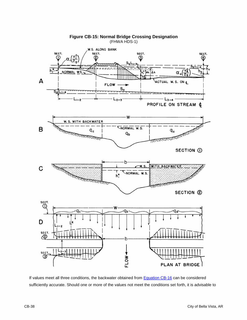
CB-38 City of Bella Vista, AR
Figure CB-15: Normal Bridge Crossing Designation
(FHWA HDS-1)
If values meet all three conditions, the backwater obtained from Equation CB-16 can be considered
sufficiently accurate. Should one or more of the values not meet the conditions set forth, it is advisable to

DRAINAGE CRITERIA MANUAL BRIDGE AND CULVERT HYDRAULIC DESIGN
City of Bella Vista, AR CB-39
use Equation CB-15 in its entirety. The use of the guides is further demonstrated in the examples given in
FHWA (1978) that should be used in all bridge design work.
8.3.3 Backwater Coefficient
The value of the overall backwater coefficient K*, which was determined experimentally, varies with:
1. Stream constriction as measured by bridge opening ratio, M.
2. Type of bridge abutment: wingwall, spill through, etc.
3. Number, size, shape, and orientation of piers in the constriction.
4. Eccentricity or asymmetric position of bridge with the floodplains.
5. Skew (bridge crosses floodplain at other than 90 degree angle).
The overall backwater coefficient K* consists of a base curve coefficient, Kb, to which are added
incremental coefficients to account for the effect of piers, eccentricity, and skew. The value of K* is
primarily dependent on the degree of constriction of the flow but also changes to a limited degree with the
other factors.
8.3.4 Effect of M and Abutment Shape (Base Curves)
Figure CB-16 shows the base curve for backwater coefficient, Kb, plotted with respect to the opening ratio,
M, for several wingwall abutments and a vertical wall type. Note how the coefficient Kb increases with
channel constriction. The several curves represent different angles of wingwalls as can be identified by
the accompanying sketches; the lower curves represent the better hydraulic shapes.
Figure CB-17 shows the relation between the backwater coefficient, Kb, and M for spill-through abutments
for three embankment slopes. A comparison of the three curves indicates that the coefficient is little
affected by embankment slope. Figures CD-16 and CB-17 are “base curves” and Kb is referred to as the
“base curve coefficient.” The base curve coefficients apply to normal crossings for specific abutment
shapes but do not include the effect of piers, eccentricity, or skew.
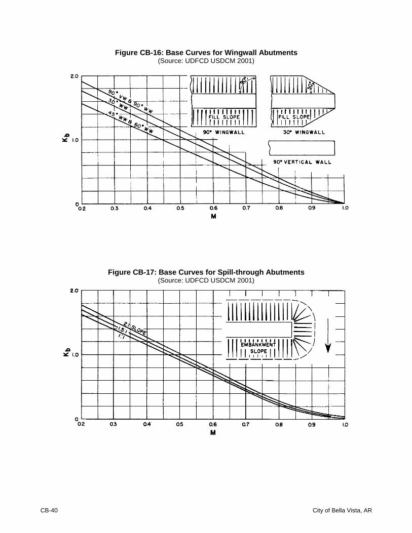
CB-40 City of Bella Vista, AR
Figure CB-16: Base Curves for Wingwall Abutments (Source: UDFCD USDCM 2001)
Figure CB-17: Base Curves for Spill-through Abutments (Source: UDFCD USDCM 2001)
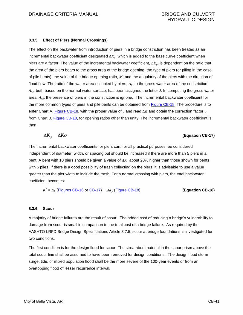
DRAINAGE CRITERIA MANUAL BRIDGE AND CULVERT HYDRAULIC DESIGN
City of Bella Vista, AR CB-41
8.3.5 Effect of Piers (Normal Crossings)
The effect on the backwater from introduction of piers in a bridge constriction has been treated as an
incremental backwater coefficient designated ∆Kp, which is added to the base curve coefficient when
piers are a factor. The value of the incremental backwater coefficient, ΔKp, is dependent on the ratio that
the area of the piers bears to the gross area of the bridge opening; the type of piers (or piling in the case
of pile bents); the value of the bridge opening ratio, M; and the angularity of the piers with the direction of
flood flow. The ratio of the water area occupied by piers, Ap, to the gross water area of the constriction,
An2, both based on the normal water surface, has been assigned the letter J. In computing the gross water
area, An2, the presence of piers in the constriction is ignored. The incremental backwater coefficient for
the more common types of piers and pile bents can be obtained from Figure CB-18. The procedure is to
enter Chart A, Figure CB-18, with the proper value of J and read ∆K and obtain the correction factor σ
from Chart B, Figure CB-18, for opening ratios other than unity. The incremental backwater coefficient is
then
KK p (Equation CB-17)
The incremental backwater coefficients for piers can, for all practical purposes, be considered
independent of diameter, width, or spacing but should be increased if there are more than 5 piers in a
bent. A bent with 10 piers should be given a value of ΔKp about 20% higher than those shown for bents
with 5 piles. If there is a good possibility of trash collecting on the piers, it is advisable to use a value
greater than the pier width to include the trash. For a normal crossing with piers, the total backwater
coefficient becomes:
K* = Kb (Figures CB-16 or CB-17) + ΔKp (Figure CB-18) (Equation CB-18)
8.3.6 Scour
A majority of bridge failures are the result of scour. The added cost of reducing a bridge’s vulnerability to
damage from scour is small in comparison to the total cost of a bridge failure. As required by the
AASHTO LRFD Bridge Design Specifications Article 3.7.5, scour at bridge foundations is investigated for
two conditions.
The first condition is for the design flood for scour. The streambed material in the scour prism above the
total scour line shall be assumed to have been removed for design conditions. The design flood storm
surge, tide, or mixed population flood shall be the more severe of the 100-year events or from an
overtopping flood of lesser recurrence interval.

CB-42 City of Bella Vista, AR
The second condition is for the check flood for scour. The stability of bridge foundation shall be
investigated for scour conditions resulting from a designated flood storm surge, tide, or mixed population
flood not exceed the 500-year event or from an overtopping flood of lesser recurrence interval. Excess
reserve beyond that required for stability under this condition is not necessary. The extreme event limit
state shall apply.
If the site conditions and low tailwater conditions near stream confluences dictate the use of a more
severe flood event for either the design or the check flood for scour, the engineer may use such flood
event.
For additional guidance and requirements, refer to the AASHTO LRFD Bridge Design Specifications.
8.4 Design Procedure
The following is a brief step-by-step outline for determination of backwater produced by a bridge
constriction:
1. Determine the magnitude and frequency of the discharge for which the bridge is to be designed.
2. Determine the stage of the stream at the bridge site for the design discharge.
3. Plot representative cross section of stream for design discharge at Section 1, if not already done
under Step 2. If the stream channel is essentially straight and the cross section substantially
uniform in the vicinity of the bridge, the natural cross section of the stream at the bridge site may
be used for this purpose.
4. Subdivide the above cross section according to marked changes in depth of flow and roughness.
Assign values of Manning's roughness coefficient, n, to each subsection. Careful judgment is
necessary in selecting these values. Refer to Chapter 7 – Open Channel Flow Design.
5. Compute conveyance and then discharge in each subsection.
6. Determine the value of the kinetic energy coefficient.
7. Plot the natural cross section under the proposed bridge based on normal water surface for
design discharge and compute the gross water area (including area occupied by piers).
8. Compute the bridge opening ratio, M, observing modified procedure for skewed crossings.
9. Obtain the value of Kb from the appropriate base curve.
10. If piers are involved, compute the value of J and obtain the incremental coefficient, ΔKp.

DRAINAGE CRITERIA MANUAL BRIDGE AND CULVERT HYDRAULIC DESIGN
City of Bella Vista, AR CB-43
11. If eccentricity is severe, compute the value of eccentricity and obtain the incremental coefficient,
ΔKe (FHWA 1978).
12. If a skewed crossing is involved, observe proper procedure in previous steps, and then obtain the
incremental coefficient, ΔKs, for proper abutment type.
13. Determine the total backwater coefficient, K*, by adding incremental coefficients to the base curve
coefficient, Kb.
14. Compute the backwater by Equation CB-16.
15. Determine the distance upstream to where the backwater effect is negligible.
Detailed steps illustrated by examples are presented in FHWA’s Hydraulic Design Series No. 1,
Hydraulics of Bridge Waterways (HDS-1 1978).
8.5 Inadequate Openings
The engineer will often encounter existing bridges and culverts that have been designed for storms
having return periods less than 100 years. In addition, bridges will be encountered which have been
improperly designed. Often the use of the orifice formula will provide a quick determination of the
adequacy or inadequacy of a bridge opening:
brbbm gHACQ 2 (Equation CB-14)
or
2
04.0
b
m
brA
QH (Equation CB-15)
in which:
Qm = Major storm discharge (ft3/s)
Cb = Bridge opening coefficient (0.6 assumed in Equation CB-14)
Ab = Area of the bridge opening (ft2)
g = Acceleration of gravity (32.2 ft/s2)
Hbr = Vertical distance from the bridge opening center point to the upstream water surface at a
distance about 10 times H upstream from the bridge, where H is the height of the bridge in
feet. It is approximately the difference between the upstream and downstream water
surfaces where the lower end of the bridge is submerged.
These expressions are valid when the water surface is above the top of the bridge opening.

CB-44 City of Bella Vista, AR
Figure CB-18: Incremental Backwater Coefficient for Pier (FHWA HDS-1)

DRAINAGE CRITERIA MANUAL BRIDGE AND CULVERT HYDRAULIC DESIGN
City of Bella Vista, AR CB-45
9.0 REFERENCES
American Association of State Highway and Transportation Officials (AASHTO), Highway Subcommittee
on Bridges and Structures. 2007. LRFD Bridge Design Specifications, 4th Ed. Washington, DC:
AASHTO
American Association of State Highway and Transportation Officials (AASHTO) Task Force for Roadside
Safety, Highway Subcommittee on Design. 1996. Roadside Design Guide. Washington, DC:
AASHTO.
———. 1987. Hydraulic Analysis. Location and Design of Bridges. Washington, DC: AASHTO.
American Concrete Pipe Association. 2000. Concrete Pipe Design Manual. Irving, TX: American
Concrete Pipe Association.
Arkansas State Highway and Transportation Department (AHTD). 1982. Drainage Manual. Little Rock,
AR: AHTD
———. 2000. Standard Drawing PCC-1, Concrete Pipe Culvert Fill Heights and Bedding. Little Rock,
AR: Arkansas State Highway and Transportation Department.
Chow, V.T. 1959. Open Channel Hydraulics. New York: McGraw-Hill Book Company, Inc.
Ginsberg, A. 1987. HY8 Culvert Analysis Microcomputer Program Applications Guide. Washington, DC:
U.S. Department of Transportation, Federal Highway Administration.
King, H.W. and E.F. Brater 1976. Handbook of Hydraulics. New York: McGraw-Hill Book Company.
New Jersey Department of Transportation (NJDOT). 2008. Soil Erosion and Sediment Control Standards.
Trenton, New Jersey: NJDOT
Rhode Island Department of Environmental Management. 1989. Soil Erosion and Sediment Control
Handbook. Providence, RI: RI DEM
Richardson, E.V. 1974. Highways in the River Environment. Washington, DC: U. S. Department of
Transportation, Federal Highway Administration.
Scourstop.com. 2008. ScourStop. 1 Sep. 2009 <http://scourstop.com/index.php>.
Urban Drainage and Flood Control District. 2001. Urban Storm Drainage Criteria Manual. Denver, CO:
Urban Drainage and Flood Control District.
U.S. Army Corp of Engineers (USACE). 1952. Hydrologic and Hydraulic Analysis, Computation of
Backwater Curves in River Channels. Engineering Manual. Washington, DC: Department of the
Army.
U.S. Bureau of Reclamation. 1960. Design of Small Dams. Denver, CO: Bureau of Reclamation.

CB-46 City of Bella Vista, AR
U.S. Federal Highway Administration (FHWA). 1960. Hydraulics of Bridge Waterways. Hydraulic Design
Series No.1. Washington, DC: FHWA.
———. 1965. Hydraulic Charts for the Selection of Highway Culverts. Hydraulic Engineering Circular No.
5. Washington, DC: U.S. Department of Transportation, Federal Highway Administration.
———. 1971. Debris Control Structures. Hydraulic Engineering Circular No. 9. Washington, DC: U.S.
Department of Transportation, Federal Highway Administration.
———. 1972b. Hydraulic Design of Improved Inlets for Culverts. Hydraulic Engineering Circular No. 13.
Washington, DC: U.S. Department of Transportation, Federal Highway Administration.
———. 1978. Hydraulics of Bridge Waterways. Hydraulic Design Series No. 1. Washington, DC:
Department of Transportation.
———. 1983. Hydraulic Design of Energy Dissipators for Culverts and Channels. Hydraulic Engineering
Circular No.14. Washington, DC: U.S. Department of Transportation, Federal Highway
Administration.
———. 1985. Hydraulic Design of Highway Culverts. Hydraulic Design Series No. 5. Washington, DC:
U.S. Department of Transportation, Federal Highway Administration.
———. 1988. Highways in the River Environment. Washington, DC: U. S. Department of Transportation,
Federal Highway Administration.
———. 1996. Federal Lands Highway Project Development and Design Manual. 1996 Metric Revision.
FHWA-DF-88-003. Washington, DC: U.S. Department of Transportation, Federal Highway
Administration.
———. 2000. Hydraulic Design of Energy Dissipators for Culverts and Channels. Hydraulic Engineering
Circular No. 14M. Washington, DC: U.S. Department of Transportation, Federal Highway
Administration.
Virginia Department of Transportation (VDOT). 2002. Drainage Manual. Richmond, Virginia: VDOT