chapter 7 configuring virtual lans...
TRANSCRIPT
Chapter 7Configuring Virtual LANs (VLANs)
This chapter describes how to configure Virtual LANs (VLANs) on HP Routing Switches.
The “Overview” section provides basic information about HP’s VLAN options. Following this section, other sections provide configuration procedures and examples.
To display configuration information for VLANs, see “Displaying VLAN Information” on page 7-60.
For complete syntax information for the CLI commands shown in this chapter, see the Command Line Interface Reference.
Most of the configuration examples in this chapter are based on CLI commands. For Web management procedures, see “Configuring VLANs Using the Web Management Interface” on page 7-54.
NOTE: For information about the GARP VLAN Registration Protocol (GVRP), see “Configuring GARP VLAN Registration Protocol (GVRP)” on page 8-1.
OverviewThis section describes the HP VLAN features. Configuration procedures and examples appear in later sections of this chapter.
Types of VLANsYou can configure the following types of VLANs on HP devices.
• Layer 2 port-based VLAN – a set of physical ports that share a common, exclusive Layer 2 broadcast domain
• Layer 3 protocol VLANs – a subset of ports within a port-based VLAN that share a common, exclusive broadcast domain for Layer 3 broadcasts of the specified protocol type
• IP sub-net VLANs – a subset of ports in a port-based VLAN that share a common, exclusive sub-net broadcast domain for a specified IP sub-net
• IPv6 VLANs – a subset of ports in a port-based VLAN that share a common, exclusive network broadcast domain for IPv6 packets
• IPX network VLANs – a subset of ports in a port-based VLAN that share a common, exclusive network broadcast domain for a specified IPX network
• AppleTalk cable VLANs – a subset of ports in a port-based VLAN that share a common, exclusive network broadcast domain for a specified AppleTalk cable range
7 - 1

Installation and Getting Started Guide
When an HP device receives a packet on a port that is a member of a VLAN, the device forwards the packet based on the following VLAN hierarchy:
• If the port belongs to an IP sub-net VLAN, IPX network VLAN, or AppleTalk cable VLAN and the packet belongs to the corresponding IP sub-net, IPX network, or AppleTalk cable range, the device forwards the packet to all the ports within that VLAN.
• If the packet is a Layer 3 packet but cannot be forwarded as described above, but the port is a member of a Layer 3 protocol VLAN for the packet’s protocol, the device forwards the packet on all the Layer 3 protocol VLAN’s ports.
• If the packet cannot be forwarded based on either of the VLAN membership types listed above, but the packet can be forwarded at Layer 2, the device forwards the packet on all the ports within the receiving port’s port-based VLAN.
Protocol VLANs differ from IP sub-net, IPX network, and AppleTalk VLANs in an important way. Protocol VLANs accept any broadcast of the specified protocol type. An IP sub-net, IPx network, or AppleTalk VLAN accepts only broadcasts for the specified IP sub-net, IPX network, or AppleTalk cable range.
NOTE: Protocol VLANs are different from IP sub-net, IPX network, and AppleTalk cable VLANs. A port-based VLAN cannot contain both an IP sub-net, IPX network, or AppleTalk cable VLAN and a protocol VLAN for the same protocol. For example, a port-based VLAN cannot contain both an IP protocol VLAN and an IP sub-net VLAN.
Layer 2 Port-Based VLANs
On all HP devices, you can configure port-based VLANs. A port-based VLAN is a subset of ports on an HP device that constitutes a Layer 2 broadcast domain.
By default, all the ports on an HP device are members of the default VLAN. Thus, all the ports on the device constitute a single Layer 2 broadcast domain. You can configure multiple port-based VLANs. When you configure a port-based VLAN, the device automatically removes the ports you add to the VLAN from the default VLAN.
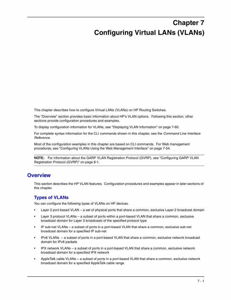
Figure 7.1 shows an example of an HP device on which a Layer 2 port-based VLAN has been configured.
Figure 7.1 HP device containing user-defined Layer 2 port-based VLAN
A port can belong to only one port-based VLAN, unless you apply 802.1q tagging to the port. 802.1q tagging allows the port to add a four-byte tag field, which contains the VLAN ID, to each packet sent on the port. You also can configure port-based VLANs that span multiple devices by tagging the ports within the VLAN. The tag enables each device that receives the packet to determine the VLAN the packet belongs to. 802.1q tagging applies only to Layer 2 VLANs, not to Layer 3 VLANs.
Default VLAN
User-configured port-based VLAN
7 - 2

Configuring Virtual LANs (VLANs)
Since each port-based VLAN is a separate Layer 2 broadcast domain, by default each VLAN runs a separate instance of the Spanning Tree Protocol (STP).
Layer 2 traffic is bridged within a port-based VLAN and Layer 2 broadcasts are sent to all the ports within the VLAN.
Layer 3 Protocol-Based VLANs
If you want some or all of the ports within a port-based VLAN to be organized according to Layer 3 protocol, you must configure a Layer 3 protocol-based VLAN within the port-based VLAN.
You can configure each of the following types of protocol-based VLAN within a port-based VLAN. All the ports in the Layer 3 VLAN must be in the same Layer 2 VLAN.
• AppleTalk – The device sends AppleTalk broadcasts to all ports within the AppleTalk protocol VLAN.
• IP – The device sends IP broadcasts to all ports within the IP protocol VLAN.
• IPv6 – The device sends IPv6 broadcasts to all ports within the IPv6 protocol VLAN.
• IPX – The device sends IPX broadcasts to all ports within the IPX protocol VLAN.
• DECnet – The device sends DECnet broadcasts to all ports within the DECnet protocol VLAN.
• NetBIOS – The device sends NetBIOS broadcasts to all ports within the NetBIOS protocol VLAN.
• Other – The device sends broadcasts for all protocol types other than those listed above to all ports within the VLAN.
Figure 7.2 shows an example of Layer 3 protocol VLANs configured within a Layer 2 port-based VLAN.
Figure 7.2 Layer 3 protocol VLANs within a Layer 2 port-based VLAN
Integrated Switch Routing (ISR)
Hewlett-Packard’ Integrated Switch Routing (ISR) feature enables VLANs configured on Routing Switches to route Layer 3 traffic from one protocol VLAN or IP sub-net, IPX network, or AppleTalk cable VLAN to another. Normally, to route traffic from one IP sub-net, IPX network, or AppleTalk cable VLAN to another, you would need to forward the traffic to an external router. The VLANs provide Layer 3 broadcast domains for these protocols but do not in themselves provide routing services for these protocols. This is true even if the source and destination IP sub-nets, IPX networks, or AppleTalk cable ranges are on the same device.
Default VLAN
User-configured port-based VLAN
Protocol VLAN, IP sub-net VLAN,IPX network VLANor AppleTalk VLAN
7 - 3
Installation and Getting Started Guide
ISR eliminates the need for an external router by allowing you to route between VLANs using virtual interfaces (VEs). A virtual interface is a logical port on which you can configure Layer 3 routing parameters. You configure a separate virtual interface on each VLAN that you want to be able to route from or to. For example, if you configure two IP sub-net VLANs on a Routing Switch, you can configure a virtual interface on each VLAN, then configure IP routing parameters for the sub-nets. Thus, the Routing Switch forwards IP sub-net broadcasts within each VLAN at Layer 2 but routes Layer 3 traffic between the VLANs using the virtual interfaces.
NOTE: The Routing Switch uses the lowest MAC address on the device (the MAC address of port 1/1) as the MAC address for all ports within all virtual interfaces you configure on the device.
The routing parameters and the syntax for configuring them are the same as when you configure a physical interface for routing. The logical interface allows the Routing Switch to internally route traffic between the protocol-based VLANs without using physical interfaces.
All the ports within a protocol-based VLAN must be in the same port-based VLAN. The protocol-based VLAN cannot have ports in multiple port-based VLANs, unless the ports in the port-based VLAN to which you add the protocol-based VLAN are 802.1q tagged.
You can configure multiple protocol-based VLANs within the same port-based VLAN. In addition, a port within a port-based VLAN can belong to multiple protocol-based VLANs of the same type or different types. For example, if you have a port-based VLAN that contains ports 1/1 – 1/10, you can configure port 1/5 as a member of an AppleTalk protocol VLAN, an IP protocol VLAN, and an IPX protocol VLAN, and so on.
IP Sub-Net, IPX Network, and AppleTalk Cable VLANs
The protocol-based VLANs described in the previous section provide separate protocol broadcast domains for specific protocols. For IP, IPX, and AppleTalk, you can provide more granular broadcast control by instead creating the following types of VLAN:
• IP sub-net VLAN – An IP sub-net broadcast domain for a specific IP sub-net.
• IPX network VLAN – An IPX network broadcast domain for a specific IPX network.
• AppleTalk cable VLAN – An AppleTalk broadcast domain for a specific cable range.
The Routing Switch sends broadcasts for the IP sub-net, IPX network, or AppleTalk cable range to all ports within the IP sub-net, IPX network, or AppleTalk cable VLAN at Layer 2.
The Routing Switch routes packets between VLANs at Layer 3. To configure an IP sub-net, IPX network, or AppleTalk cable VLAN to route, you must add a virtual interface to the VLAN, then configure the appropriate routing parameters on the virtual interface.
NOTE: The Routing Switch routes packets between VLANs of the same protocol. The Routing Switch cannot route from one protocol to another.
NOTE: IP sub-net VLANs are not the same thing as IP protocol VLANs. An IP protocol VLAN sends all IP broadcasts on the ports within the IP protocol VLAN. An IP sub-net VLAN sends only the IP sub-net broadcasts for the sub-net of the VLAN. You cannot configure an IP protocol VLAN and an IP sub-net VLAN within the same port-based VLAN.
This note also applies to IPX protocol VLANs and IPX network VLANs, and to AppleTalk protocol VLANs and AppleTalk cable VLANs.
Default VLANBy default, all the ports on an HP device are in a single port-based VLAN. This VLAN is called DEFAULT-VLAN and is VLAN number 1. HP devices do not contain any protocol VLANs or IP sub-net, IPX network, or AppleTalk cable VLANs by default.
7 - 4
Configuring Virtual LANs (VLANs)
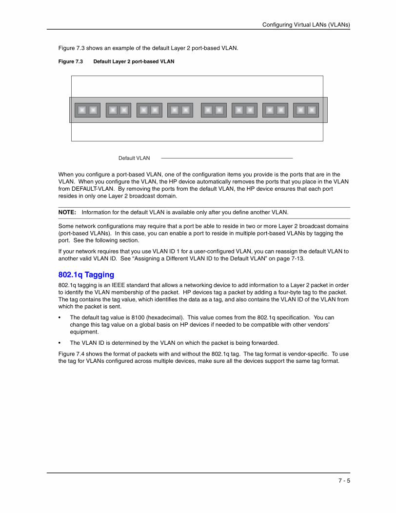
Figure 7.3 shows an example of the default Layer 2 port-based VLAN.
Figure 7.3 Default Layer 2 port-based VLAN
When you configure a port-based VLAN, one of the configuration items you provide is the ports that are in the VLAN. When you configure the VLAN, the HP device automatically removes the ports that you place in the VLAN from DEFAULT-VLAN. By removing the ports from the default VLAN, the HP device ensures that each port resides in only one Layer 2 broadcast domain.
NOTE: Information for the default VLAN is available only after you define another VLAN.
Some network configurations may require that a port be able to reside in two or more Layer 2 broadcast domains (port-based VLANs). In this case, you can enable a port to reside in multiple port-based VLANs by tagging the port. See the following section.
If your network requires that you use VLAN ID 1 for a user-configured VLAN, you can reassign the default VLAN to another valid VLAN ID. See “Assigning a Different VLAN ID to the Default VLAN” on page 7-13.
802.1q Tagging802.1q tagging is an IEEE standard that allows a networking device to add information to a Layer 2 packet in order to identify the VLAN membership of the packet. HP devices tag a packet by adding a four-byte tag to the packet. The tag contains the tag value, which identifies the data as a tag, and also contains the VLAN ID of the VLAN from which the packet is sent.
• The default tag value is 8100 (hexadecimal). This value comes from the 802.1q specification. You can change this tag value on a global basis on HP devices if needed to be compatible with other vendors’ equipment.
• The VLAN ID is determined by the VLAN on which the packet is being forwarded.
Figure 7.4 shows the format of packets with and without the 802.1q tag. The tag format is vendor-specific. To use the tag for VLANs configured across multiple devices, make sure all the devices support the same tag format.
Default VLAN
7 - 5

Installation and Getting Started Guide
Figure 7.4 Packet containing HP’s 802.1QVLAN tag
NOTE: You cannot configure a port to be a member of the default port-based VLAN and another port-based VLAN at the same time. Once you add a port to a port-based VLAN, the port is no longer a member of the default VLAN. The port returns to the default VLAN only if you delete the other VLAN(s) that contains the port.
If you configure a VLAN that spans multiple devices, you need to use tagging only if a port connecting one of the devices to the other is a member of more than one port-based VLAN. If a port connecting one device to the other is a member of only a single port-based VLAN, tagging is not required.
If you use tagging on multiple devices, each device must be configured for tagging and must use the same tag value. In addition, the implementation of tagging must be compatible on the devices. The tagging on all HP devices is compatible with other HP devices.
6 bytes
DestinationAddress
2 bytes
LengthField
Up to 1496 bytes
DataField
4 bytes
CRC IEEE 802.3
6 bytes
SourceAddress
6 bytes
DestinationAddress
2 bytes
TypeField
Up to 1500 bytes
DataField
4 bytes
CRC Ethernet II6 bytes
SourceAddress
2 bytes
LengthField
Up to 1496 bytes
DataField
4 bytes
CRC IEEE 802.3 with 802.1q tag
2 bytes
TypeField
Up to 1500 bytes
DataField
4 bytes
CRC Ethernet II with 802.1q tag
4 bytes
802.1qTag
4 bytes
802.1qTag
802.1q Tagged Packet Format
Octet 1 Octet 2
Tag Protocol Id (TPID)5 6 7 8 Octet 4
VLAN ID (12 bits)1 2 3 4802.1p(3 bits)
6 bytes
DestinationAddress
2 bytes
LengthField
Up to 1496 bytes
DataField
4 bytes
CRC IEEE 802.36 bytes
SourceAddress
6 bytes
DestinationAddress
2 bytes
TypeField
Up to 1500 bytes
DataField
4 bytes
CRC Ethernet II6 bytes
SourceAddress
Untagged Packet Format
7 - 6

Configuring Virtual LANs (VLANs)
Figure 7.5 shows an example of two devices that have the same Layer 2 port-based VLANs configured across them. Notice that only one of the VLANs requires tagging.
Figure 7.5 VLANs configured across multiple devices
Spanning Tree Protocol (STP)STP is disabled by default on HP Routing Switches.
Also by default, each port-based VLAN has a separate instance of STP. Thus, when STP is globally enabled, each port-based VLAN on the device runs a separate spanning tree.
You can enable or disable STP on the following levels:
• Globally – Affects all ports on the device.
NOTE: If you configure a port-based VLAN on the device, the VLAN has the same STP state as the default STP state on the device. On Routing Switches, new VLANs have STP disabled by default. You can enable or disable STP in each VLAN separately. In addition, you can enable or disable STP on individual ports.
• Port-based VLAN – Affects all ports within the specified port-based VLAN.
STP is a Layer 2 protocol. Thus, you cannot enable or disable STP for individual protocol VLANs or for IP sub-net, IPX network, or AppleTalk cable VLANs. The STP state of a port-based VLAN containing these other types of VLANs determines the STP state for all the Layer 2 broadcasts within the port-based VLAN. This is true even though Layer 3 protocol broadcasts are sent on Layer 2 within the VLAN.
It is possible that STP will block one or more ports in a protocol VLAN that uses a virtual interface to route to other VLANs. For IP protocol and IP sub-net VLANs, even though some of the physical ports of the virtual interface are blocked, the virtual interface can still route so long as at least one port in the virtual interface’s protocol VLAN is not blocked by STP.
User-configured port-based VLAN
VLAN A VLAN A/B VLAN B
VLAN A VLAN A/B VLAN B
Segment 1
Segment 2
7 - 7
Installation and Getting Started Guide
If you enable Single STP (SSTP) on the device, the ports in all VLANs on which STP is enabled become members of a single spanning tree. The ports in VLANs on which STP is disabled are excluded from the single spanning tree.
For more information, see “Configuring Spanning Tree Protocol (STP)” on page 6-1.
Virtual InterfacesA virtual interface is a logical routing interface that HP Routing Switches use to route Layer 3 protocol traffic between protocol VLANs.
HP devices send Layer 3 traffic at Layer 2 within a protocol VLAN. However, Layer 3 traffic from one protocol VLAN to another must be routed.
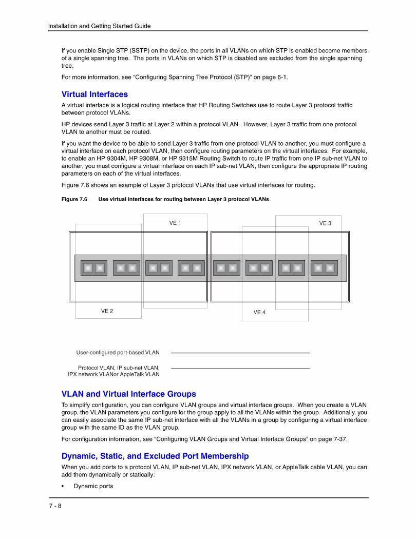
If you want the device to be able to send Layer 3 traffic from one protocol VLAN to another, you must configure a virtual interface on each protocol VLAN, then configure routing parameters on the virtual interfaces. For example, to enable an HP 9304M, HP 9308M, or HP 9315M Routing Switch to route IP traffic from one IP sub-net VLAN to another, you must configure a virtual interface on each IP sub-net VLAN, then configure the appropriate IP routing parameters on each of the virtual interfaces.
Figure 7.6 shows an example of Layer 3 protocol VLANs that use virtual interfaces for routing.
Figure 7.6 Use virtual interfaces for routing between Layer 3 protocol VLANs
VLAN and Virtual Interface GroupsTo simplify configuration, you can configure VLAN groups and virtual interface groups. When you create a VLAN group, the VLAN parameters you configure for the group apply to all the VLANs within the group. Additionally, you can easily associate the same IP sub-net interface with all the VLANs in a group by configuring a virtual interface group with the same ID as the VLAN group.
For configuration information, see “Configuring VLAN Groups and Virtual Interface Groups” on page 7-37.
Dynamic, Static, and Excluded Port MembershipWhen you add ports to a protocol VLAN, IP sub-net VLAN, IPX network VLAN, or AppleTalk cable VLAN, you can add them dynamically or statically:
• Dynamic ports
User-configured port-based VLAN
Protocol VLAN, IP sub-net VLAN,IPX network VLANor AppleTalk VLAN
VE 2
VE 1
VE 4
VE 3
7 - 8

Configuring Virtual LANs (VLANs)
• Static ports
You also can explicitly exclude ports.
Dynamic Ports
Dynamic ports are added to a VLAN when you create the VLAN. However, if a dynamically added port does not receive any traffic for the VLAN’s protocol within ten minutes, the port is removed from the VLAN. However, the port remains a candidate for port membership. Thus, if the port receives traffic for the VLAN’s protocol, the device adds the port back to the VLAN.
After the port is added back to the VLAN, the port can remain an active member of the VLAN up to 20 minutes without receiving traffic for the VLAN’s protocol. If the port ages out, it remains a candidate for VLAN membership and is added back to the VLAN when the VLAN receives protocol traffic. At this point, the port can remain in the VLAN up to 20 minutes without receiving traffic for the VLAN’s protocol, and so on.
Unless you explicitly add a port statically or exclude a port, the port is a dynamic port and thus can be an active member of the VLAN, depending on the traffic it receives.
NOTE: You cannot configure dynamic ports in an AppleTalk cable VLAN. The ports in an AppleTalk cable VLAN must be static. However, ports in an AppleTalk protocol VLAN can be dynamic or static.
Figure 7.7 shows an example of a VLAN with dynamic ports. Dynamic ports not only join and leave the VLAN according to traffic, but also allow some broadcast packets of other protocol types to “leak” through the VLAN. See “Broadcast Leaks” on page 7-10.
Figure 7.7 VLAN with dynamic ports—all ports are active when you create the VLAN
User-configured port-based VLAN
Active Dynamic Ports
Active Ports Candidate Ports
7 - 9

Installation and Getting Started Guide
Ports in a new protocol VLAN that do not receive traffic for the VLAN’s protocol age out after 10 minutes and become candidate ports. Figure 7.8 shows what happens if a candidate port receives traffic for the VLAN’s protocol.
Figure 7.8 VLAN with dynamic ports—candidate ports become active again if they receive protocol traffic
Static Ports
Static ports are permanent members of the protocol VLAN. The ports remain active members of the VLAN regardless of whether the ports receive traffic for the VLAN’s protocol. You must explicitly identify the port as a static port when you add it to the VLAN. Otherwise, the port is dynamic and is subject to aging out.
In addition, static ports never “leak” broadcast packets of other protocol types. (See “Broadcast Leaks” on page 7-10.)
Excluded Ports
If you want to prevent a port in a port-based VLAN from ever becoming a member of a protocol, IP sub-net, IPX network, or AppleTalk cable VLAN configured in the port-based VLAN, you can explicitly exclude the port. You exclude the port when you configure the protocol, IP sub-net, IPX network, or AppleTalk cable VLAN.
Broadcast Leaks
A dynamic port becomes a member of a Layer 3 protocol VLAN when traffic from the VLAN's protocol is received on the port. After this point, the port remains an active member of the protocol VLAN, unless the port does not receive traffic from the VLAN's protocol for 20 minutes. If the port does not receive traffic for the VLAN's protocol for 20 minutes, the port ages out and is no longer an active member of the VLAN.
To enable a host that has been silent for awhile to send and receive packets, the dynamic ports that are currently members of the Layer 3 protocol VLAN "leak" Layer 3 broadcast packets to the ports that have aged out. When a host connected to one of the aged out ports responds to a leaked broadcast, the port is added to the protocol VLAN again.
To "leak" Layer 3 broadcast traffic, an active port sends 1/8th of the Layer 3 broadcast traffic to the inactive (aged out) ports.
Static ports do not age out and do not leak broadcast packets.
User-configured port-based VLAN
Active Dynamic Ports
Active Ports Candidate Ports
7 - 10

Configuring Virtual LANs (VLANs)
Super Aggregated VLANsYou can aggregate multiple VLANs within another VLAN. This feature allows you to construct Layer 2 paths and channels. This feature is particularly useful for Virtual Private Network (VPN) applications in which you need to provide a private, dedicated Ethernet connection for an individual client to transparently reach its sub-net across multiple networks.
For an application example and configuration information, see “Configuring Super Aggregated VLANs” on page 7-41.
Trunk Group Ports and VLAN MembershipA trunk group is a set of physical ports that are configured to act as a single physical interface. Each trunk group’s port configuration is based on the configuration of the lead port, which is the lowest numbered port in the group.
If you add a trunk group’s lead port to a VLAN, all of the ports in the trunk group become members of that VLAN.
Summary of VLAN Configuration RulesA hierarchy of VLANs exists between the Layer 2 and Layer 3 protocol-based VLANs:
• Port-based VLANs are at the lowest level of the hierarchy.
• Layer 3 protocol-based VLANs, IP, IPv6, IPX, AppleTalk, Decnet, and NetBIOS are at the middle level of the hierarchy.
• IP sub-net, IPX network, and AppleTalk cable VLANs are at the top of the hierarchy.
NOTE: You cannot have a protocol-based VLAN and a sub-net or network VLAN of the same protocol type in the same port-based VLAN. For example, you can have an IPX protocol VLAN and IP sub-net VLAN in the same port-based VLAN, but you cannot have an IP protocol VLAN and an IP sub-net VLAN in the same port-based VLAN, nor can you have an IPX protocol VLAN and an IPX network VLAN in the same port-based VLAN.
As an HP device receives packets, the VLAN classification starts from the highest level VLAN first. Therefore, if an interface is configured as a member of both a port-based VLAN and an IP protocol VLAN, IP packets coming into the interface are classified as members of the IP protocol VLAN because that VLAN is higher in the VLAN hierarchy.
Multiple VLAN Membership Rules
• A port can belong to multiple, unique, overlapping Layer 3 protocol-based VLANs without VLAN tagging.
• A port can belong to multiple, overlapping Layer 2 port-based VLANs only if the port is a tagged port. Packets sent out of a tagged port use an 802.1q-tagged frame.
• When both port and protocol-based VLANs are configured on a given device, all protocol VLANs must be strictly contained within a port-based VLAN. A protocol VLAN cannot include ports from multiple port-based VLANs. This rule is required to ensure that port-based VLANs remain loop-free Layer 2 broadcast domains.
• IP protocol VLANs and IP sub-net VLANs cannot operate concurrently on the system or within the same port-based VLAN.
• IPX protocol VLANs and IPX network VLANs cannot operate concurrently on the system or within the same port-based VLAN.
• If you first configure IP and IPX protocol VLANs before deciding to partition the network by IP sub-net and IPX network VLANs, then you need to delete those VLANs before creating the IP sub-net and IPX network VLANs.
• Removing a configured port-based VLAN from a Hewlett-Packard Routing Switch automatically removes any protocol-based VLAN, IP sub-net VLAN, AppleTalk cable VLAN, or IPX network VLAN, or any Virtual Ethernet router interfaces defined within the Port-based VLAN.
7 - 11
Installation and Getting Started Guide
Routing Between VLANsHP Routing Switches can locally route IP, IPX, and Appletalk between VLANs defined within a single router. All other routable protocols or protocol VLANs (for example, DecNet) must be routed by another external router capable of routing the protocol.
Virtual Interfaces You need to configure virtual interfaces if an IP, IPX, or Appletalk protocol VLAN, IP sub-net VLAN, AppleTalk cable VLAN, or IPX network VLAN needs to route protocols to another port-based VLAN on the same router. A virtual routing interface can be associated with the ports in only a single port-based VLAN. Virtual router interfaces must be defined at the highest level of the VLAN hierarchy.
If you do not need to further partition the port-based VLAN by defining separate Layer 3 VLANs, you can define a single virtual interface at the port-based VLAN level and enable IP, IPX, and Appletalk routing on a single virtual interface.
Bridging and Routing the Same Protocol Simultaneously on the Same DeviceSome configurations may require simultaneous switching and routing of the same single protocol across different sets of ports on the same router. When IP, IPX, or Appletalk routing is enabled on an HP Routing Switch, you can route these protocols on specific interfaces while bridging them on other interfaces. In this scenario, you can create two separate backbones for the same protocol, one bridged and one routed.
To bridge IP, IPX, or Appletalk at the same time these protocols are being routed, you need to configure an IP protocol, IP sub-net, IPX protocol, IPX network, or Appletalk protocol VLAN and not assign a virtual interface to the VLAN. Packets for these protocols are bridged or switched at Layer 2 across ports on the router that are included in the Layer 3 VLAN. If these VLANs are built within port-based VLANs, they can be tagged across a single set of backbone fibers to create separate Layer 2 switched and Layer 3 routed backbones for the same protocol on a single physical backbone.
Routing Between VLANs Using Virtual InterfacesHP calls the ability to route between VLANs with virtual interfaces Integrated Switch Routing (ISR). There are some important concepts to understand before designing an ISR backbone.
Virtual router interfaces can be defined on port-based, IP protocol, IP sub-net, IPX protocol, IPX network, AppleTalk protocol, and AppleTalk cable VLANs.
To create any type of VLAN on an HP Routing Switch, Layer 2 forwarding must be enabled. When Layer 2 forwarding is enabled, the Routing Switch becomes a Switch on all ports for all non-routable protocols.
If the router interfaces for IP, IPX, or AppleTalk are configured on physical ports, then routing occurs independent of the Spanning Tree Protocol (STP). However, if the router interfaces are defined for any type VLAN, they are virtual interfaces and are subject to the rules of STP.
If your backbone is comprised of virtual interfaces all within the same STP domain, it is a bridged backbone, not a routed one. This means that the set of backbone interfaces that are blocked by STP will be blocked for routed protocols as well. The routed protocols will be able to cross these paths only when the STP state of the link is FORWARDING. This problem is easily avoided by proper network design.
When designing an ISR network, pay attention to your use of virtual interfaces and the spanning-tree domain. If Layer 2 switching of your routed protocols (IP, IPX, AppleTalk) is not required across the backbone, then the use of virtual interfaces can be limited to edge switch ports within each router. Full backbone routing can be achieved by configuring routing on each physical interface that connects to the backbone. Routing is independent of STP when configured on a physical interface.
If your ISR design requires that you switch IP, IPX, or Appletalk at Layer 2 while simultaneously routing the same protocols over a single backbone, then create multiple port-based VLANs and use VLAN tagging on the backbone links to separate your Layer 2 switched and Layer 3 routed networks.
There is a separate STP domain for each port-based VLAN. Routing occurs independently across port-based VLANs or STP domains. You can define each end of each backbone link as a separate tagged port-based VLAN.
7 - 12
Configuring Virtual LANs (VLANs)
Routing will occur independently across the port-based VLANs. Because each port-based VLAN’s STP domain is a single point-to-point backbone connection, you are guaranteed to never have an STP loop. STP will never block the virtual router interfaces within the tagged port-based VLAN, and you will have a fully routed backbone.
Dynamic Port AssignmentAll Switch ports are dynamically assigned to any non-routable VLAN on HP Routing Switches. To maintain explicit control of the VLAN, you can explicitly exclude ports when configuring any non-routable Layer 3 VLAN on an HP Routing Switch.
If you do not want the ports to have dynamic membership, you can add them statically. This eliminates the need to explicitly exclude the ports that you do not want to participate in a particular Layer 3 VLAN.
Assigning a Different VLAN ID to the Default VLANWhen you enable port-based VLANs, all ports in the system are added to the default VLAN. By default, the default VLAN ID is “VLAN 1”. The default VLAN is not configurable. If you want to use the VLAN ID “VLAN 1” as a configurable VLAN, you can assign a different VLAN ID to the default VLAN.
To reassign the default VLAN to a different VLAN ID, enter the following command:
HP9300(config)# default-vlan-id 4095
Syntax: [no] default-vlan-d <vlan-id>
You must specify a valid VLAN ID that is not already in use. For example, if you have already defined VLAN 10, do not try to use “10” as the new VLAN ID for the default VLAN. Valid VLAN IDs are numbers from 1 – 4096.
NOTE: Changing the default VLAN name does not change the properties of the default VLAN. Changing the name allows you to use the VLAN ID “1” as a configurable VLAN.
Assigning Trunk Group PortsWhen a “lead” trunk group port is assigned to a VLAN, all other members of the trunk group are automatically added to that VLAN. A lead port is the first port of a trunk group port range; for example, “1” in 1 – 4 or “5” in 5 – 8. See “Trunk Group Rules” in the Installation and Getting Started Guide for more information.
Configuring Port-Based VLANsPort-based VLANs allow you to provide separate spanning tree protocol (STP) domains or broadcast domains on a port-by-port basis.
This section describes how to perform the following tasks for port-based VLANs using the CLI:
• Create a VLAN.
• Delete a VLAN.
• Modify a VLAN.
• Assign a higher priority to the VLAN.
• Change a VLAN’s priority.
• Enable or disable STP on the VLAN.
EXAMPLE:
Figure 7.9 shows a simple port-based VLAN configuration using a single HP Routing Switch. All ports within each VLAN are untagged. One untagged port within each VLAN is used to connect the Routing Switch to another Routing Switch (in this example, an HP 9308M) for Layer 3 connectivity between the two port-based VLANs.
7 - 13

Installation and Getting Started Guide
Figure 7.9 Port-based VLANs 222 and 333
To create the two port-based VLANs shown in Figure 7.9, use the following method.
USING THE CLI
HP9300(config)# vlan 222 by portHP9300(config-vlan-222)# untag e 1/1 to 1/8HP9300(config-vlan-222)# vlan 333 by portHP9300(config-vlan-333)# untag e 1/9 to 1/16
Syntax: vlan <vlan-id> by port
Syntax: untagged ethernet <portnum> [to <portnum> | ethernet <portnum>]
EXAMPLE:
Figure 7.10 shows a more complex port-based VLAN configuration using multiple Routing Switches and IEEE 802.1q VLAN tagging. The backbone link connecting the three Routing Switches is tagged. One untagged port within each port-based VLAN on 9308M-A connects each separate network wide Layer 2 broadcast domain to the router for Layer 3 forwarding between broadcast domains. The STP priority is configured to force 9308M-A to be the root bridge for VLANs RED and BLUE. The STP priority on 9308M-B is configured so that 9308M-B is the root bridge for VLANs GREEN and BROWN.
Port 1/2IP sub-net 2IPX network 2AppleTalk cable range 200AppleTalk zone “CTP”
9308M
Ports 1/5 - 1/8IP sub-net 2IPX network 2AppleTalk cable range 2AppleTalk zone “CTP”
9308M
Port 1/1IP sub-net 1IPX network 1AppleTalk cable range 100AppleTalk zone “Prepress”
Layer port-based VLAN 333Ports 1/5 - 1/8
Port 1/5
Layer port-based VLAN 222Ports 1/1 - 1/4
Ports 1/2 - 1/4IP sub-net 1IPX network 1AppleTalk cable range 100AppleTalk zone “Prepress”
Port 1/1
7 - 14

Configuring Virtual LANs (VLANs)
Figure 7.10 More complex port-based VLAN
To configure the Port-based VLANs on the HP 9308M Routing Switches in Figure 7.10, use the following method.
USING THE CLI
Configuring 9308M-A
Enter the following commands to configure 9308M-A:
HP9300> enableHP9300# configure terminalHP9300(config)# hostname HP9308-AHP9308-A(config)# vlan 2 name BROWNHP9308-A(config-vlan-2)# untag ethernet 1/1 to 1/4 ethernet 1/17HP9308-A(config-vlan-2)# tag ethernet 1/25 to 1/26HP9308-A(config-vlan-2)# spanning-treeHP9308-A(config-vlan-2)# vlan 3 name GREENHP9308-A(config-vlan-3)# untag ethernet 1/5 to 1/8 ethernet 1/18HP9308-A(config-vlan-3)# tag ethernet 1/25 to 1/26HP9308-A(config-vlan-3)# spanning-treeHP9308-A(config-vlan-3)# vlan 4 name BLUEHP9308-A(config-vlan-4)# untag ethernet 1/9 to 1/12 ethernet 1/19HP9308-A(config-vlan-4)# tag ethernet 1/25 to 1/26HP9308-A(config-vlan-4)# spanning-tree
9308M-C
IP sub-net 2IPX network 2Atalk 200.1Zone “B”
port 1/5
IP sub-net 1IPX network 1Atalk 100.1Zone “A”
9308M-A
VLAN 3“GREEN”Ports 1/6 - 1/8IP sub 2IPX net 2Atalk 200Zone “B”
VLAN 2“BROWN”Ports 1/1 - 1/3IP sub 1IPX net 1Atalk 100Zone “A”
9308M-B
9304M
Root Bridge forVLAN “BROWN”
Root Bridge forVLAN “GREEN”
port 1/4
= STP blocked VLAN
VLAN “BROWN”
VLAN “GREEN”
VLAN 3“GREEN”Ports 1/6 - 1/8IP sub 2IPX net 2Atalk 200Zone “B”
VLAN 2“BROWN”Ports 1/1 - 1/3IP sub 1IPX net 1Atalk 100Zone “A”
VLAN 3“GREEN”Ports 1/6 - 1/8IP sub 2IPX net 2Atalk 200Zone “B”
VLAN 2“BROWN”Ports 1/1 - 1/3IP sub 1IPX net 1Atalk 100Zone “A”
7 - 15
Installation and Getting Started Guide
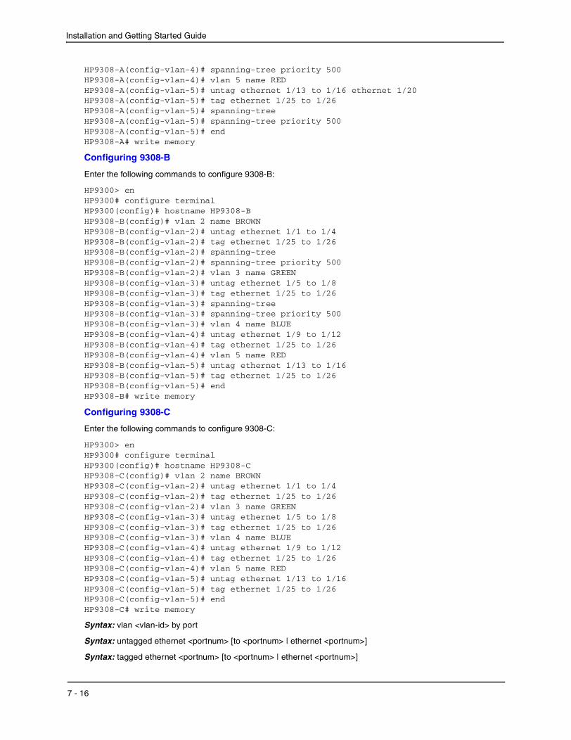
HP9308-A(config-vlan-4)# spanning-tree priority 500HP9308-A(config-vlan-4)# vlan 5 name REDHP9308-A(config-vlan-5)# untag ethernet 1/13 to 1/16 ethernet 1/20HP9308-A(config-vlan-5)# tag ethernet 1/25 to 1/26HP9308-A(config-vlan-5)# spanning-treeHP9308-A(config-vlan-5)# spanning-tree priority 500HP9308-A(config-vlan-5)# endHP9308-A# write memory
Configuring 9308-B
Enter the following commands to configure 9308-B:
HP9300> enHP9300# configure terminalHP9300(config)# hostname HP9308-BHP9308-B(config)# vlan 2 name BROWNHP9308-B(config-vlan-2)# untag ethernet 1/1 to 1/4HP9308-B(config-vlan-2)# tag ethernet 1/25 to 1/26HP9308-B(config-vlan-2)# spanning-treeHP9308-B(config-vlan-2)# spanning-tree priority 500HP9308-B(config-vlan-2)# vlan 3 name GREENHP9308-B(config-vlan-3)# untag ethernet 1/5 to 1/8HP9308-B(config-vlan-3)# tag ethernet 1/25 to 1/26HP9308-B(config-vlan-3)# spanning-treeHP9308-B(config-vlan-3)# spanning-tree priority 500HP9308-B(config-vlan-3)# vlan 4 name BLUEHP9308-B(config-vlan-4)# untag ethernet 1/9 to 1/12HP9308-B(config-vlan-4)# tag ethernet 1/25 to 1/26HP9308-B(config-vlan-4)# vlan 5 name REDHP9308-B(config-vlan-5)# untag ethernet 1/13 to 1/16HP9308-B(config-vlan-5)# tag ethernet 1/25 to 1/26HP9308-B(config-vlan-5)# endHP9308-B# write memory
Configuring 9308-C
Enter the following commands to configure 9308-C:
HP9300> enHP9300# configure terminalHP9300(config)# hostname HP9308-CHP9308-C(config)# vlan 2 name BROWNHP9308-C(config-vlan-2)# untag ethernet 1/1 to 1/4HP9308-C(config-vlan-2)# tag ethernet 1/25 to 1/26HP9308-C(config-vlan-2)# vlan 3 name GREENHP9308-C(config-vlan-3)# untag ethernet 1/5 to 1/8HP9308-C(config-vlan-3)# tag ethernet 1/25 to 1/26HP9308-C(config-vlan-3)# vlan 4 name BLUEHP9308-C(config-vlan-4)# untag ethernet 1/9 to 1/12HP9308-C(config-vlan-4)# tag ethernet 1/25 to 1/26HP9308-C(config-vlan-4)# vlan 5 name REDHP9308-C(config-vlan-5)# untag ethernet 1/13 to 1/16HP9308-C(config-vlan-5)# tag ethernet 1/25 to 1/26HP9308-C(config-vlan-5)# endHP9308-C# write memory
Syntax: vlan <vlan-id> by port
Syntax: untagged ethernet <portnum> [to <portnum> | ethernet <portnum>]
Syntax: tagged ethernet <portnum> [to <portnum> | ethernet <portnum>]
7 - 16

Configuring Virtual LANs (VLANs)
Syntax: [no] spanning-tree
Syntax: spanning-tree [ethernet <portnum> path-cost <value> priority <value>] forward-delay <value> hello-time <value> maximum-age <time> priority <value>
Modifying a Port-Based VLANYou can make the following modifications to a port-based VLAN:
• Add or delete a VLAN port.
• Change its priority.
• Enable or disable STP.
Removing a Port-Based VLAN
Suppose you want to remove VLAN 5 from the example in Figure 7.10. To do so, use the following procedure.
USING THE CLI
1. Access the global CONFIG level of the CLI on 9308-A by entering the following commands:
HP9308-A> enableNo password has been assigned yet...HP9308-A# configure terminalHP9308-A(config)#
2. Enter the following command:
HP9308-A(config)# no vlan 5HP9308-A(config)#
3. Enter the following commands to exit the CONFIG level and save the configuration to the system-config file on flash memory:
HP9308-A(config)#HP9308-A(config)# endHP9308-A# write memoryHP9308-A#
4. Repeat steps 1 – 3 on 9308-B.
Syntax: no vlan <vlan-id> by port
Removing a Port from a VLAN
Suppose you want to remove port 1/11 from VLAN 4 on 9308-A shown in Figure 7.10. To do so, use the following procedure.
USING THE CLI
1. Access the global CONFIG level of the CLI on 9308-A by entering the following command:
HP9308-A> enableNo password has been assigned yet...HP9308-A# configure terminalHP9308-A(config)#
2. Access the level of the CLI for configuring port-based VLAN 4 by entering the following command:
HP9308-A(config)#HP9308-A(config)# vlan 4HP9308-A(config-vlan-4)#
3. Enter the following commands:
HP9308-A(config-vlan-4)#HP9308-A(config-vlan-4)# no untag ethernet 1/11deleted port ethe 1/11 from port-vlan 4.
7 - 17

Installation and Getting Started Guide
HP9308-A(config-vlan-4)#
4. Enter the following commands to exit the VLAN CONFIG mode and save the configuration to the system-config file on flash memory:
HP9308-A(config-vlan-4)#HP9308-A(config-vlan-4)# endHP9308-A# write memoryHP9308-A#
NOTE: Beginning in software release 07.5.00, you can remove all the ports from a port-based VLAN without losing the rest of the VLAN’s configuration. However, you cannot configure an IP address on a virtual interface unless the VLAN contains ports. If the VLAN has a virtual interface, the virtual interface’s IP address is deleted when the ports associated with the interface are deleted. The rest of the VLAN configuration is retained.
In software releases earlier than 07.5.00, if you remove all the ports from a VLAN, the software removes the VLAN configuration entirely.
Assigning a Higher Priority to a VLAN
Suppose you wanted to give all traffic on Purple VLAN 2 in Figure 7.10 higher priority than all the other VLANs. Use the following procedure to do so.
USING THE CLI
1. Access the global CONFIG level of the CLI on 9308-A by entering the following command:
HP9308-A> enableNo password has been assigned yet...HP9308-A# configure terminalHP9308-A(config)#
2. Access the level of the CLI for configuring port-based VLAN 2 by entering the following command:
HP9308-A(config)#HP9308-A(config)# vlan 2HP9308-A(config-vlan-2)#
3. Enable all packets exiting the Routing Switch on VLAN 2 to transmit from the highest priority hardware queue of each transmit interface. For Chassis devices, possible levels are 0 (normal) – 7 (highest).
HP9308-A(config-vlan-2)#HP9308-A(config-vlan-2)# priority 7HP9308-A(config-vlan-2)#
4. Enter the following commands to exit the VLAN CONFIG mode and save the configuration to the system-config file on flash memory:
HP9308-A(config-vlan-2)#HP9308-A(config-vlan-2)# endHP9308-A# write memoryHP9308-A#
5. Repeat steps 1 – 4 on 9308-B.
Syntax: vlan <vlan-id> by port
Syntax: priority 0 – 7
Enable Spanning Tree on a VLAN
The spanning tree bridge and port parameters are configurable using one CLI command set at the Global Configuration Level of each Port-based VLAN. Suppose you want to enable the IEEE 802.1d STP across VLAN 3. To do so, use the following method.
7 - 18
Configuring Virtual LANs (VLANs)
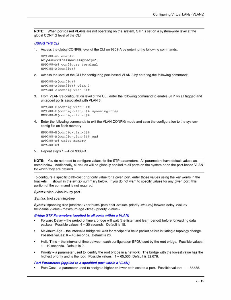
NOTE: When port-based VLANs are not operating on the system, STP is set on a system-wide level at the global CONFIG level of the CLI.
USING THE CLI
1. Access the global CONFIG level of the CLI on 9308-A by entering the following commands:
HP9308-A> enableNo password has been assigned yet...HP9308-A# configure terminalHP9308-A(config)#
2. Access the level of the CLI for configuring port-based VLAN 3 by entering the following command:
HP9308-A(config)#HP9308-A(config)# vlan 3HP9308-A(config-vlan-3)#
3. From VLAN 3’s configuration level of the CLI, enter the following command to enable STP on all tagged and untagged ports associated with VLAN 3.
HP9308-B(config-vlan-3)#HP9308-B(config-vlan-3)# spanning-treeHP9308-B(config-vlan-3)#
4. Enter the following commands to exit the VLAN CONFIG mode and save the configuration to the system-config file on flash memory:
HP9308-B(config-vlan-3)#HP9308-B(config-vlan-3)# endHP9308-B# write memoryHP9308-B#
5. Repeat steps 1 – 4 on 9308-B.
NOTE: You do not need to configure values for the STP parameters. All parameters have default values as noted below. Additionally, all values will be globally applied to all ports on the system or on the port-based VLAN for which they are defined.
To configure a specific path-cost or priority value for a given port, enter those values using the key words in the brackets [ ] shown in the syntax summary below. If you do not want to specify values for any given port, this portion of the command is not required.
Syntax: vlan <vlan-id> by port
Syntax: [no] spanning-tree
Syntax: spanning-tree [ethernet <portnum> path-cost <value> priority <value>] forward-delay <value> hello-time <value> maximum-age <time> priority <value>
Bridge STP Parameters (applied to all ports within a VLAN)• Forward Delay – the period of time a bridge will wait (the listen and learn period) before forwarding data
packets. Possible values: 4 – 30 seconds. Default is 15.
• Maximum Age – the interval a bridge will wait for receipt of a hello packet before initiating a topology change. Possible values: 6 – 40 seconds. Default is 20.
• Hello Time – the interval of time between each configuration BPDU sent by the root bridge. Possible values: 1 – 10 seconds. Default is 2.
• Priority – a parameter used to identify the root bridge in a network. The bridge with the lowest value has the highest priority and is the root. Possible values: 1 – 65,535. Default is 32,678.
Port Parameters (applied to a specified port within a VLAN)• Path Cost – a parameter used to assign a higher or lower path cost to a port. Possible values: 1 – 65535.
7 - 19
Installation and Getting Started Guide
Default is (1000/Port Speed) for Half-Duplex ports and is (1000/Port Speed)/2 for Full-Duplex ports.
• Priority – value determines when a port will be rerouted in relation to other ports. Possible values: 0 – 255. Default is 128.
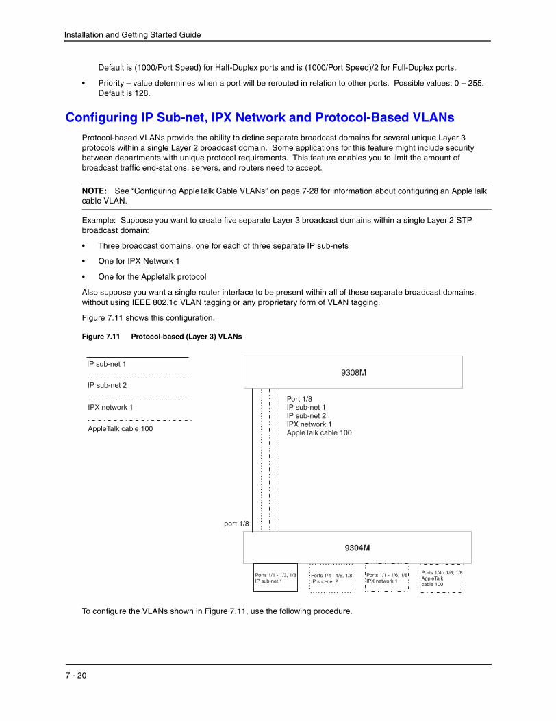
Configuring IP Sub-net, IPX Network and Protocol-Based VLANsProtocol-based VLANs provide the ability to define separate broadcast domains for several unique Layer 3 protocols within a single Layer 2 broadcast domain. Some applications for this feature might include security between departments with unique protocol requirements. This feature enables you to limit the amount of broadcast traffic end-stations, servers, and routers need to accept.
NOTE: See “Configuring AppleTalk Cable VLANs” on page 7-28 for information about configuring an AppleTalk cable VLAN.
Example: Suppose you want to create five separate Layer 3 broadcast domains within a single Layer 2 STP broadcast domain:
• Three broadcast domains, one for each of three separate IP sub-nets
• One for IPX Network 1
• One for the Appletalk protocol
Also suppose you want a single router interface to be present within all of these separate broadcast domains, without using IEEE 802.1q VLAN tagging or any proprietary form of VLAN tagging.
Figure 7.11 shows this configuration.
Figure 7.11 Protocol-based (Layer 3) VLANs
To configure the VLANs shown in Figure 7.11, use the following procedure.
Port 1/8IP sub-net 1
IPX network 1AppleTalk cable 100
IP sub-net 2
9304M
9308M
AppleTalk cable 100
IP sub-net 1
IP sub-net 2
IPX network 1
port 1/8
Ports 1/4 - 1/6, 1/8IP sub-net 2
Ports 1/1 - 1/6, 1/8IPX network 1
Ports 1/4 - 1/6, 1/8AppleTalkcable 100
Ports 1/1 - 1/3, 1/8IP sub-net 1
7 - 20

Configuring Virtual LANs (VLANs)
USING THE CLI
1. To permanently assign ports 1/1 – 1/8 and port 1/25 to IP sub-net VLAN 1.1.1.0, enter the following commands:
HP9304> enNo password has been assigned yet...HP9304# config tHP9304(config)#HP9304(config)# ip-subnet 1.1.1.0/24 name GreenHP9304(config-ip-subnet)# no dynamicHP9304(config-ip-subnet)# static ethernet 1/1 to 1/8 ethernet 1/25
2. To permanently assign ports 1/9 – 1/16 and port 1/25 to IP sub-net VLAN 1.1.2.0, enter the following commands:
HP9304(config-ip-subnet)# ip-subnet 1.1.2.0/24 name YellowHP9304(config-ip-subnet)# no dynamicHP9304(config-ip-subnet)# static ethernet 1/9 to 1/16 ethernet 1/25
3. To permanently assign ports 1/17 – 1/25 to IP sub-net VLAN 1.1.3.0, enter the following commands:
HP9304(config-ip-subnet)# ip-subnet 1.1.3.0/24 name BrownHP9304(config-ip-subnet)# no dynamicHP9304(config-ip-subnet)# static ethernet 1/17 to 1/25
4. To permanently assign ports 1/1 – 1/12 and port 1/25 to IPX network 1 VLAN, enter the following commands:
HP9304(config-ip-subnet)# ipx-network 1 ethernet_802.3 name BlueHP9304(config-ipx-network)# no dynamicHP9304(config-ipx-network)# static ethernet 1/1 to 1/12 ethernet 1/25HP9304(config-ipx-network)#
5. To permanently assign ports 1/12 – 1/25 to Appletalk VLAN, enter the following commands:
HP9304(config-ipx-proto)# atalk-proto name RedHP9304(config-atalk-proto)# no dynamicHP9304(config-atalk-proto)# static ethernet 1/13 to 1/25HP9304(config-atalk-proto)# endHP9304# write memoryHP9304#
Syntax: ip-subnet <ip-addr> <ip-mask> [name <string>]
Syntax: ipx-network <ipx-network-number> <frame-encapsulation-type> netbios-allow | netbios-disallow [name <string>]
Syntax: ip-proto | ipx-proto | atalk-proto | decnet-proto | netbios-proto | other-proto static | exclude | dynamic ethernet <portnum> [to <portnum>] [name <string>]
Configuring an IPv6 Protocol VLANYou can configure a protocol-based VLAN as a broadcast domain for IPv6 traffic. When the Routing Switch receives an IPv6 multicast packet (a packet with 06 in the version field and 0xFF as the beginning of the destination address), the Routing Switch forwards the packet to all other ports in the VLAN.
NOTE: The Routing Switch forwards all IPv6 multicast packets to all ports in the VLAN except the port that received the packet, and does not distinguish among sub-net directed multicasts.
You can add the VLAN ports as static ports or dynamic ports. A static port is always an active member of the VLAN. Dynamic ports within any protocol VLAN age out after 10 minutes, if no member protocol traffic is received on a port within the VLAN. The aged out port, however, remains as a candidate dynamic port for that VLAN. The port becomes active in the VLAN again if member protocol traffic is received on that port.
7 - 21

Installation and Getting Started Guide
Once a port is re-activated, the aging out period for the port is reset to 20 minutes. Each time a member protocol packet is received by a candidate dynamic port (aged out port) the port becomes active again and the aging out period is reset for 20 minutes.
To configure an IPv6 VLAN, enter commands such as the following:
HP9300(config)# vlan 2HP9300(config-vlan-2)# untag ethernet 1/1 to 1/8HP9300(config-vlan-2)# ipv6-proto name V6HP9300(config-ipv6-subnet)# static ethernet 1/1 to 1/6HP9300(config-ipv6-subnet)# dynamic
The first two commands configure a port-based VLAN and add ports 1/1 – 1/8 to the VLAN. The remaining commands configure an IPv6 VLAN within the port-based VLAN. The static command adds ports 1/1 – 1/6 as static ports, which do not age out. The dynamic command adds the remaining ports, 1/7 – 1/8, as dynamic ports. These ports are subject to aging as described above.
Syntax: [no] ipv6-proto [name <string>]
Routing Between VLANs Using Virtual InterfacesHP Routing Switches offer the ability to create a virtual interface within a Layer 2 STP port-based VLAN or within each Layer 3 protocol, IP sub-net, or IPX network VLAN. This combination of multiple Layer 2 and/or Layer 3 broadcast domains and virtual interfaces are the basis for Hewlett-Packard’s very powerful Integrated Switch Routing (ISR) technology. ISR is very flexible and can solve many networking problems. The following example is meant to provide ideas by demonstrating some of the concepts of ISR.
Example: Suppose you want to move routing out to each of three buildings in a network. Remember that the only protocols present on VLAN 2 and VLAN 3 are IP and IPX. Therefore, you can eliminate tagged ports 25 and 26 from both VLAN 2 and VLAN 3 and create new tagged port-based VLANs to support separate IP sub-nets and IPX networks for each backbone link.
You also need to create unique IP sub-nets and IPX networks within VLAN 2 and VLAN 3 at each building. This will create a fully routed IP and IPX backbone for VLAN 2 and VLAN 3. However, VLAN 4 has no protocol restrictions across the backbone. In fact there are requirements for NetBIOS and DecNet to be bridged among the three building locations. The IP sub-net and IPX network that exists within VLAN 4 must remain a flat Layer 2 switched STP domain. You enable routing for IP and IPX on a virtual interface only on HP9304-A. This will provide the flat IP and IPX segment with connectivity to the rest of the network. Within VLAN 4 IP and IPX will follow the STP topology. All other IP sub-nets and IPX networks will be fully routed and have use of all paths at all times during normal operation.
Figure 7.12 shows the configuration described above.
7 - 22

Configuring Virtual LANs (VLANs)
Figure 7.12 Routing between protocol-based VLANs
To configure the Layer 3 VLANs and virtual interfaces on the HP 9304M Routing Switch in Figure 7.12, use the following procedure.
VLAN 8
= STP blocked VLAN
VLAN 7Port 26 (tagged)VE 6-IP sub-net 8-IPX network 8
VLAN 2Ports 1 - 4VE 1-IP sub-net 6
VLAN 8Ports 5 - 8VE 2-IPX network 6
VLAN 3Ports 9 - 16IP sub-net 7 (ports 9 - 12, VE 3)IPX network 7 (ports 13 - 16, VE 4)VE 3-IP sub-net 7-OSPF area 0.0.0.0VE 4-IPX network 7
VLAN 4Ports 17 - 24 (untagged)Ports 25 - 26 (tagged)
VLAN 5Port 25 (tagged)VE 5-IP sub-net 4-OSPF area 0.0.0.0-IPX network 4
VLAN 6Port 26 (tagged)VE 6-IP sub-net 5-OSPF area 0.0.0.0-IPX network 5
VLAN 2Ports 1 - 4VE 1-IP sub-net 9-OSPF area 0.0.0.0
VLAN 8Ports 5 - 8VE 2-IPX network 9
VLAN 3Ports 9 - 16IP sub-net 10 (ports 9 - 12, VE 3)IPX network 10 (ports 13 - 16, VE 4)VE 3-IP sub-net 10-OSPF area 0.0.0.0VE 4-IPX network 10
VLAN 4Ports 17 - 24 (untagged)Ports 25 - 26 (tagged)
VLAN 7Port 25 (tagged)VE 5-IP sub-net 8-OSPF area 0.0.0.0-IPX network 8
9304 B
VLAN 6Port 26 (tagged)VE 7-IP sub-net 5-OSPF 0.0.0.0-IPX network 5
VLAN 2Ports 1 - 4VE 1-IP sub-net 2-OSPF area 0.0.0.0
VLAN 8Ports 5 - 8VE 2-IPX network 2
VLAN 3Ports 9 - 16IP sub-net 1 (ports 9 - 12, VE 3)IPX network 1 (ports 13 - 16, VE 4)VE 3-IP sub-net 1-OSPF area 0.0.0.0VE 4-IPX network 1
VLAN 4Ports 17 - 24 (untagged)Ports 25 - 26 (tagged)VE 5-IP sub-net 3-OSPF area 0.0.0.0-IPX network 3
VLAN 5Port 25 (tagged)VE 6-IP sub-net 4-OSPF area 0.0.0.0-IPX network 4
VLAN 6
VLAN 7
VLAN 5
VE 4, VE 7(STP is blocking VE 4)
VLAN 2
VLAN 3
VLAN 4
VE 4, VE 5
VE 4, VE 6
9304 A
9304 C
7 - 23
Installation and Getting Started Guide
USING THE CLI
Configuring HP9304-A
Enter the following commands to configure HP9304-A. The following commands enable OSPF or RIP routing and IPX routing.
HP9304> enNo password has been assigned yet...HP9304# configure terminalHP9304(config)# hostname HP9304-AHP9304-A(config)# router ospfHP9304-A(config-ospf-router)# area 0.0.0.0 normalHP9304-A(config-ospf-router)# router ipxipx routing enabled for next power cycle.Please save configuration to flash and reboot.HP9304-A(config-ospf-router)#
The following commands create the port-based VLAN 2. In the previous example, an external HP 9304M defined the router interfaces for VLAN 2. With ISR, routing for VLAN 2 is done locally within each HP 9304M. Therefore, there are two ways you can solve this problem. One way is to create a unique IP sub-net and IPX network VLAN, each with its own virtual interface and unique IP or IPX address within VLAN 2 on each HP 9304M. In this example, this is the configuration used for VLAN 3. The second way is to split VLAN 2 into two separate port-based VLANs and create a virtual router interface within each port-based VLAN. Later in this example, this second option is used to create a port-based VLAN 8 to show that there are multiple ways to accomplish the same task with ISR.
You also need to create the Other-Protocol VLAN within port-based VLAN 2 and 8 to prevent unwanted protocols from being Layer 2 switched within port-based VLAN 2 or 8. Note that the only port-based VLAN that requires STP in this example is VLAN 4. You will need to configure the rest of the network to prevent the need to run STP.
HP9304-A(config-ospf-router)# vlan 2 name IP-Subnet_1.1.2.0/24HP9304-A(config-vlan-2)# untag e 1/1 to 1/4HP9304-A(config-vlan-2)# no spanning-treeHP9304-A(config-vlan-2)# router-interface ve1HP9304-A(config-vlan-2)# other-proto name block_other_protocolsHP9304-A(config-vlan-other-proto)# no dynamicHP9304-A(config-vlan-other-proto)# exclude e 1/1 to 1/4
Once you have defined the port-based VLAN and created the virtual interface, you need to configure the virtual interface just as you would configure a physical interface.
HP9304-A(config-vlan-other-proto)# interface ve1HP9304-A(config-vif-1)# ip address 1.1.2.1/24HP9304-A(config-vif-1)# ip ospf area 0.0.0.0
Do the same thing for VLAN 8.
HP9304-A(config-vif-1)# vlan 8 name IPX_Network2HP9304-A(config-vlan-8)# untag ethernet 1/5 to 1/8HP9304-A(config-vlan-8)# no spanning-treeHP9304-A(config-vlan-8)# router-interface ve 2HP9304-A(config-vlan-8)# other-proto name block-other-protocolsHP9304-A(config-vlan-other-proto)# no dynamicHP9304-A(config-vlan-other-proto)# exclude ethernet 1/5 to 1/8HP9304-A(config-vlan-other-proto)# int ve2HP9304-A(config-vif-2)# ipx network 2 ethernet_802.3HP9304-A(config-vif-2)#
The next thing you need to do is create VLAN 3. This is very similar to the previous example with the addition of virtual interfaces to the IP sub-net and IPX network VLANs. Also there is no need to exclude ports from the IP sub-net and IPX network VLANs on the router.
HP9304-A(config-vif-2)# vlan 3 name IP_Sub_&_IPX_Net_VLAN
7 - 24
Configuring Virtual LANs (VLANs)
HP9304-A(config-vlan-3)# untag e 1/9 to 1/16HP9304-A(config-vlan-3)# no spanning-treeHP9304-A(config-vlan-3)# ip-subnet 1.1.1.0/24HP9304-A(config-vlan-ip-subnet)# static e 1/9 to 1/12HP9304-A(config-vlan-ip-subnet)# router-interface ve3HP9304-A(config-vlan-ip-subnet)# ipx-network 1 ethernet_802.3HP9304-A(config-vlan-ipx-network)# static e 1/13 to 1/16HP9304-A(config-vlan-ipx-network)# router-interface ve4HP9304-A(config-vlan-ipx-network)# other-proto name block-other-protocolsHP9304-A(config-vlan-other-proto)# exclude e 1/9 to 1/16HP9304-A(config-vlan-other-proto)# no dynamicHP9304-A(config-vlan-other-proto)# interface ve 3HP9304-A(config-vif-3)# ip addr 1.1.1.1/24HP9304-A(config-vif-3)# ip ospf area 0.0.0.0HP9304-A(config-vif-3)# int ve4HP9304-A(config-vif-4)# ipx network 1 ethernet_802.3HP9304-A(config-vif-4)#
Now configure VLAN 4. Remember this is a flat segment that, in the previous example, obtained its IP default gateway and IPX router services from an external HP 9304M. In this example, HP9304-A will provide the routing services for VLAN 4. You also want to configure the STP priority for VLAN 4 to make HP9304-A the root bridge for this VLAN.
HP9304-A(config-vif-4)# vlan 4 name Bridged_ALL_ProtocolsHP9304-A(config-vlan-4)# untag ethernet 1/17 to 1/24HP9304-A(config-vlan-4)# tag ethernet 1/25 to 1/26HP9304-A(config-vlan-4)# spanning-treeHP9304-A(config-vlan-4)# spanning-tree priority 500HP9304-A(config-vlan-4)# router-interface ve5HP9304-A(config-vlan-4)# int ve5HP9304-A(config-vif-5)# ip address 1.1.3.1/24HP9304-A(config-vif-5)# ip ospf area 0.0.0.0HP9304-A(config-vif-5)# ipx network 3 ethernet_802.3HP9304-A(config-vif-5)#
It is time to configure a separate port-based VLAN for each of the routed backbone ports (Ethernet 25 and 26). If you do not create a separate tagged port-based VLAN for each point-to-point backbone link, you need to include tagged interfaces for Ethernet 25 and 26 within VLANs 2, 3, and 8. This type of configuration makes the entire backbone a single STP domain for each VLAN 2, 3, and 8. This is the configuration used in the example in “Configuring IP Sub-net, IPX Network and Protocol-Based VLANs” on page 7-20. In this scenario, the virtual interfaces within port-based VLANs 2, 3, and 8 will be accessible using only one path through the network. The path that is blocked by STP is not available to the routing protocols until it is in the STP FORWARDING state.
HP9304-A(config-vif-5)# vlan 5 name Rtr_BB_to_Bldg.2HP9304-A(config-vlan-5)# tag e 1/25HP9304-A(config-vlan-5)# no spanning-treeHP9304-A(config-vlan-5)# router-interface ve6HP9304-A(config-vlan-5)# vlan 6 name Rtr_BB_to_Bldg.3HP9304-A(config-vlan-6)# tag ethernet 1/26HP9304-A(config-vlan-6)# no spanning-treeHP9304-A(config-vlan-6)# router-interface ve7HP9304-A(config-vlan-6)# int ve6HP9304-A(config-vif-6)# ip addr 1.1.4.1/24HP9304-A(config-vif-6)# ip ospf area 0.0.0.0HP9304-A(config-vif-6)# ipx network 4 ethernet_802.3HP9304-A(config-vif-6)# int ve7HP9304-A(config-vif-7)# ip addr 1.1.5.1/24HP9304-A(config-vif-7)# ip ospf area 0.0.0.0HP9304-A(config-vif-7)# ipx network 5 ethernet_802.3HP9304-A(config-vif-7)#
7 - 25

Installation and Getting Started Guide
This completes the configuration for HP9304-A. The configuration for HP9304-B and C is very similar except for a few issues.
• IP sub-nets and IPX networks configured on HP9304-B and HP9304-C must be unique across the entire network, except for the backbone port-based VLANs 5, 6, and 7 where the sub-net is the same but the IP address must change.
• There is no need to change the default priority of STP within VLAN 4.
• There is no need to include a virtual router interface within VLAN 4.
• The backbone VLAN between HP9304-B and HP9304-C must be the same at both ends and requires a new VLAN ID. The VLAN ID for this port-based VLAN is VLAN 7.
Configuration for HP9304-B
Enter the following commands to configure HP9304-B.
HP9304> enNo password has been assigned yet...HP9304# config tHP9304(config)# hostname HP9304-BHP9304-B(config)# router ospfHP9304-B(config-ospf-router)# area 0.0.0.0 normalHP9304-B(config-ospf-router)# router ipxHP9304-B(config-ospf-router)# vlan 2 name IP-Subnet_1.1.6.0/24HP9304-B(config-vlan-2)# untag e 1/1 to 1/4HP9304-B(config-vlan-2)# no spanning-treeHP9304-B(config-vlan-2)# router-interface ve1HP9304-B(config-vlan-2)# other-proto name block-other-protocolsHP9304-B(config-vlan-other-proto)# no dynamicHP9304-B(config-vlan-other-proto)# exclude e 1/1 to 1/4HP9304-B(config-vlan-other-proto)# int ve1HP9304-B(config-vif-1)# ip addr 1.1.6.1/24HP9304-B(config-vif-1)# ip ospf area 0.0.0.0HP9304-B(config-vif-1)# vlan 8 name IPX_Network6HP9304-B(config-vlan-8)# untag e 1/5 to 1/8HP9304-B(config-vlan-8)# no spanHP9304-B(config-vlan-8)# router-int ve2HP9304-B(config-vlan-8)# other-proto name block-other-protocolsHP9304-B(config-vlan-other-proto)# no dynamicHP9304-B(config-vlan-other-proto)# exclude e 1/5 to 1/8HP9304-B(config-vlan-other-proto)# int ve2HP9304-B(config-vif-2)# ipx net 6 ethernet_802.3HP9304-B(config-vif-2)# vlan 3 name IP_Sub_&_IPX_Net_VLANHP9304-B(config-vlan-3)# untag e 1/9 to 1/16HP9304-B(config-vlan-3)# no spanning-treeHP9304-B(config-vlan-3)# ip-subnet 1.1.7.0/24HP9304-B(config-vlan-ip-subnet)# static e 1/9 to 1/12HP9304-B(config-vlan-ip-subnet)# router-interface ve3HP9304-B(config-vlan-ip-subnet)# ipx-network 7 ethernet_802.3HP9304-B(config-vlan-ipx-network)# static e 1/13 to 1/16HP9304-B(config-vlan-ipx-network)# router-interface ve4HP9304-B(config-vlan-ipx-network)# other-proto name block-other-protocolsHP9304-B(config-vlan-other-proto)# exclude e 1/9 to 1/16HP9304-B(config-vlan-other-proto)# no dynamicHP9304-B(config-vlan-other-proto)# interface ve 3HP9304-B(config-vif-3)# ip addr 1.1.7.1/24HP9304-B(config-vif-3)# ip ospf area 0.0.0.0HP9304-B(config-vif-3)# int ve4HP9304-B(config-vif-4)# ipx network 7 ethernet_802.3HP9304-B(config-vif-4)# vlan 4 name Bridged_ALL_Protocols
7 - 26

Configuring Virtual LANs (VLANs)
HP9304-B(config-vlan-4)# untag ethernet 1/17 to 1/24HP9304-B(config-vlan-4)# tag ethernet 1/25 to 1/26HP9304-B(config-vlan-4)# spanning-treeHP9304-B(config-vlan-4)# vlan 5 name Rtr_BB_to_Bldg.1HP9304-B(config-vlan-5)# tag e 1/25HP9304-B(config-vlan-5)# no spanning-treeHP9304-B(config-vlan-5)# router-interface ve5HP9304-B(config-vlan-5)# vlan 7 name Rtr_BB_to_Bldg.3HP9304-B(config-vlan-7)# tag ethernet 1/26HP9304-B(config-vlan-7)# no spanning-treeHP9304-B(config-vlan-7)# router-interface ve6HP9304-B(config-vlan-7)# int ve5HP9304-B(config-vif-5)# ip addr 1.1.4.2/24HP9304-B(config-vif-5)# ip ospf area 0.0.0.0HP9304-B(config-vif-5)# ipx network 4 ethernet_802.3HP9304-B(config-vif-5)# int ve6HP9304-B(config-vif-6)# ip addr 1.1.8.1/24HP9304-B(config-vif-6)# ip ospf area 0.0.0.0HP9304-B(config-vif-6)# ipx network 8 ethernet_802.3HP9304-B(config-vif-6)#
Configuration for HP9304-C
Enter the following commands to configure HP9304-C.
HP9304> enNo password has been assigned yet...HP9304# config tHP9304(config)# hostname HP9304-CHP9304-C(config)# router ospfHP9304-C(config-ospf-router)# area 0.0.0.0 normalHP9304-C(config-ospf-router)# router ipxHP9304-C(config-ospf-router)# vlan 2 name IP-Subnet_1.1.9.0/24HP9304-C(config-vlan-2)# untag e 1/1 to 1/4HP9304-C(config-vlan-2)# no spanning-treeHP9304-C(config-vlan-2)# router-interface ve1HP9304-C(config-vlan-2)# other-proto name block-other-protocolsHP9304-C(config-vlan-other-proto)# no dynamicHP9304-C(config-vlan-other-proto)# exclude e 1/1 to 1/4HP9304-C(config-vlan-other-proto)# int ve1HP9304-C(config-vif-1)# ip addr 1.1.9.1/24HP9304-C(config-vif-1)# ip ospf area 0.0.0.0HP9304-C(config-vif-1)# vlan 8 name IPX_Network9HP9304-C(config-vlan-8)# untag e 1/5 to 1/8HP9304-C(config-vlan-8)# no spanHP9304-C(config-vlan-8)# router-int ve2HP9304-C(config-vlan-8)# other-proto name block-other-protocolsHP9304-C(config-vlan-other-proto)# no dynamicHP9304-C(config-vlan-other-proto)# exclude e 1/5 to 1/8HP9304-C(config-vlan-other-proto)# int ve2HP9304-C(config-vif-2)# ipx net 9 ethernet_802.3HP9304-C(config-vif-2)# vlan 3 name IP_Sub_&_IPX_Net_VLANHP9304-C(config-vlan-3)# untag e 1/9 to 1/16HP9304-C(config-vlan-3)# no spanning-treeHP9304-C(config-vlan-3)# ip-subnet 1.1.10.0/24HP9304-C(config-vlan-ip-subnet)# static e 1/9 to 1/12HP9304-C(config-vlan-ip-subnet)# router-interface ve3HP9304-C(config-vlan-ip-subnet)# ipx-network 10 ethernet_802.3HP9304-C(config-vlan-ipx-network)# static e 1/13 to 1/16HP9304-C(config-vlan-ipx-network)# router-interface ve4
7 - 27
Installation and Getting Started Guide
HP9304-C(config-vlan-ipx-network)# other-proto name block-other-protocolsHP9304-C(config-vlan-other-proto)# exclude e 1/9 to 1/16HP9304-C(config-vlan-other-proto)# no dynamicHP9304-C(config-vlan-other-proto)# interface ve 3HP9304-C(config-vif-3)# ip addr 1.1.10.1/24HP9304-C(config-vif-3)# ip ospf area 0.0.0.0HP9304-C(config-vif-3)# int ve4HP9304-C(config-vif-4)# ipx network 10 ethernet_802.3HP9304-C(config-vif-4)# vlan 4 name Bridged_ALL_ProtocolsHP9304-C(config-vlan-4)# untag ethernet 1/17 to 1/24HP9304-C(config-vlan-4)# tag ethernet 1/25 to 1/26HP9304-C(config-vlan-4)# spanning-treeHP9304-C(config-vlan-4)# vlan 7 name Rtr_BB_to_Bldg.2HP9304-C(config-vlan-7)# tag e 1/25HP9304-C(config-vlan-7)# no spanning-treeHP9304-C(config-vlan-7)# router-interface ve5HP9304-C(config-vlan-7)# vlan 6 name Rtr_BB_to_Bldg.1HP9304-C(config-vlan-6)# tag ethernet 1/26HP9304-C(config-vlan-6)# no spanning-treeHP9304-C(config-vlan-6)# router-interface ve6HP9304-C(config-vlan-6)# int ve5HP9304-C(config-vif-5)# ip addr 1.1.8.2/24HP9304-C(config-vif-5)# ip ospf area 0.0.0.0HP9304-C(config-vif-5)# ipx network 8 ethernet_802.3HP9304-C(config-vif-5)# int ve6HP9304-C(config-vif-6)# ip addr 1.1.5.2/24HP9304-C(config-vif-6)# ip ospf area 0.0.0.0HP9304-C(config-vif-6)# ipx network 5 ethernet_802.3HP9304-C(config-vif-6)#
Configuring AppleTalk Cable VLANs
You can configure up to eight AppleTalk cable VLANs within a port-based VLAN.
To configure an AppleTalk cable VLAN, you create a port-based VLAN, then create up to eight cable VLANs within the port-based VLAN. You create the AppleTalk cable VLAN by assigning a number to the VLAN, optionally naming the cable VLAN, assigning ports from the port-based VLAN, and specifying the router interface (virtual interface) on which the Routing Switch will send and receive traffic for the cable VLAN.
All the ports in an AppleTalk cable VLAN are within the same AppleTalk cable range. The device switches traffic within the VLAN and routes traffic between VLANs.
Configuration GuidelinesUse the following guidelines when configuring AppleTalk cable VLANs:
• Up to eight AppleTalk cable VLANs are supported in a protocol-based VLAN. Each VLAN must be numbered from 1 – 8.
• Each AppleTalk cable VLAN can have only one router interface. The router interface must be a virtual interface.
• The AppleTalk cable VLANs cannot overlap. Thus, you cannot use the same port in more than one AppleTalk cable VLAN.
• You must add the ports to the AppleTalk cable VLAN using the static option. You cannot use the dynamic or exclude options.
• You cannot have an AppleTalk cable VLAN and an AppleTalk protocol VLAN in the same port-based VLAN. If you already have an AppleTalk protocol VLAN in the port-based VLAN, you must delete the AppleTalk protocol VLAN first, then configure the AppleTalk cable VLAN.
7 - 28
Configuring Virtual LANs (VLANs)
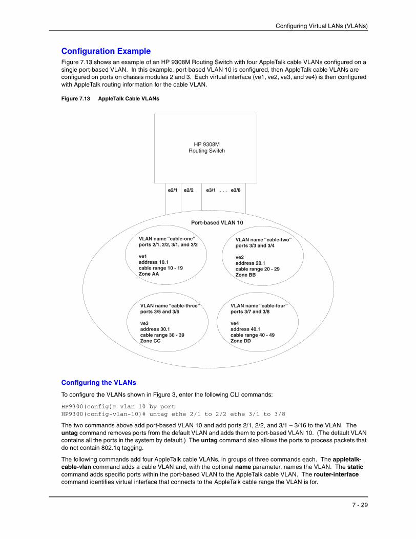
Configuration ExampleFigure 7.13 shows an example of an HP 9308M Routing Switch with four AppleTalk cable VLANs configured on a single port-based VLAN. In this example, port-based VLAN 10 is configured, then AppleTalk cable VLANs are configured on ports on chassis modules 2 and 3. Each virtual interface (ve1, ve2, ve3, and ve4) is then configured with AppleTalk routing information for the cable VLAN.
Figure 7.13 AppleTalk Cable VLANs
Configuring the VLANs
To configure the VLANs shown in Figure 3, enter the following CLI commands:
HP9300(config)# vlan 10 by portHP9300(config-vlan-10)# untag ethe 2/1 to 2/2 ethe 3/1 to 3/8
The two commands above add port-based VLAN 10 and add ports 2/1, 2/2, and 3/1 – 3/16 to the VLAN. The untag command removes ports from the default VLAN and adds them to port-based VLAN 10. (The default VLAN contains all the ports in the system by default.) The untag command also allows the ports to process packets that do not contain 802.1q tagging.
The following commands add four AppleTalk cable VLANs, in groups of three commands each. The appletalk-cable-vlan command adds a cable VLAN and, with the optional name parameter, names the VLAN. The static command adds specific ports within the port-based VLAN to the AppleTalk cable VLAN. The router-interface command identifies virtual interface that connects to the AppleTalk cable range the VLAN is for.
e3/1 e3/8. . .e2/1 e2/2
Port-based VLAN 10
VLAN name “cable-four”ports 3/7 and 3/8
ve4address 40.1cable range 40 - 49Zone DD
VLAN name “cable-one”ports 2/1, 2/2, 3/1, and 3/2
ve1address 10.1cable range 10 - 19Zone AA
VLAN name “cable-two”ports 3/3 and 3/4
ve2address 20.1cable range 20 - 29Zone BB
VLAN name “cable-three”ports 3/5 and 3/6
ve3address 30.1cable range 30 - 39Zone CC
HP 9308MRouting Switch
7 - 29
Installation and Getting Started Guide
HP9300(config-vlan-10)# appletalk-cable-vlan 1 name cable-oneHP9300(config-vlan-10)# static ethe 2/1 to 2/2 ethe 3/1 to 3/2HP9300(config-vlan-10)# router-interface ve 1HP9300(config-vlan-10)# appletalk-cable-vlan 2 name cable-twoHP9300(config-vlan-10)# static ethe 3/3 to 3/4HP9300(config-vlan-10)# router-interface ve 2HP9300(config-vlan-10)# appletalk-cable-vlan 3 name cable-threeHP9300(config-vlan-10)# static ethe 3/5 to 3/6HP9300(config-vlan-10)# router-interface ve 3HP9300(config-vlan-10)# appletalk-cable-vlan 4 name cable-fourHP9300(config-vlan-10)# static ethe 3/7 to 3/8HP9300(config-vlan-10)# router-interface ve 4
Syntax: appletalk-cable-vlan <vlan-id> [name <string>]
The <vlan-id> can be from 1 – 8.
The name <string> parameter specifies a name and can be a string up to 32 characters long.
Configuring the Router Interfaces
The following commands configure the router interfaces (virtual interfaces) associated with the AppleTalk cable VLANs. The interface ve commands add the virtual interfaces to the system. (The router-interface commands above refer to these interfaces but do not add them. You must add the interfaces using the interface ve command.)
For each virtual interface, additional commands configure the AppleTalk routing parameters for the interface. Notice that each virtual interface has a separate set of routing parameters. The routing parameters on each virtual interface are independent of the routing parameters on other virtual interfaces. Since each AppleTalk cable VLAN is associated with a separate virtual interface, each AppleTalk cable VLAN has a distinct set of routing parameters, separate from the routing parameters on other AppleTalk VLANs. In effect, each virtual interface contains a separate AppleTalk router.
The appletalk address command configures the AppleTalk interface address on the virtual interface. The appletalk cable-range command specifies the cable range for the network. The appletalk routing command enables AppleTalk routing on the virtual interface. The zone-name commands add zones to the network. For information about the AppleTalk routing commands, see the “Configuring AppleTalk” chapter in the Advanced Configuration and Management Guide.
The write memory command at the end of the example saves the configuration to the startup-config file.
HP9300(config-vlan-10)# interface ve 1HP9300(config-vif-1)# appletalk cable-range 10 - 19HP9300(config-vif-1)# appletalk address 10.1HP9300(config-vif-1)# appletalk zone-name AAHP9300(config-vif-1)# appletalk routingHP9300(config-vif-1)# interface ve 2HP9300(config-vif-2)# appletalk cable-range 20 - 29HP9300(config-vif-2)# appletalk address 20.1HP9300(config-vif-2)# appletalk zone-name BBHP9300(config-vif-2)# appletalk routingHP9300(config-vif-2)# interface ve 3HP9300(config-vif-3)# appletalk cable-range 30 - 39HP9300(config-vif-3)# appletalk address 30.1HP9300(config-vif-3)# appletalk zone-name CCHP9300(config-vif-3)# appletalk routingHP9300(config-vif-3)# interface ve 4HP9300(config-vif-4)# appletalk cable-range 40 - 49HP9300(config-vif-4)# appletalk address 40.1HP9300(config-vif-4)# appletalk zone-name DDHP9300(config-vif-4)# appletalk routingHP9300(config-vif-4)# write memory
7 - 30

Configuring Virtual LANs (VLANs)
Configuring Protocol VLANs With Dynamic PortsThe configuration examples for protocol VLANs in the sections above show how to configure the VLANs using static ports. You also can configure the following types of protocol VLANs with dynamic ports:
• AppleTalk protocol
• IP protocol
• IPX protocol
• IP sub-net
• IPX network
NOTE: The software does not support dynamically adding ports to AppleTalk cable VLANs. Conceptually, an AppleTalk cable VLAN comprises a single network cable, connected to a single port. Therefore, dynamic addition and removal of ports is not applicable.
NOTE: You cannot route to or from protocol VLANs with dynamically added ports.
Aging of Dynamic PortsWhen you add the ports to the VLAN, the software automatically adds them all to the VLAN. However, dynamically added ports age out. If the age time for a dynamic port expires, the software removes the port from the VLAN. If that port receives traffic for the IP sub-net or IPX network, the software adds the port to the VLAN again and starts the aging timer over. Each time the port receives traffic for the VLAN's IP sub-net or IPX network, the aging timer starts over.
Dynamic ports within any protocol VLAN age out after 10 minutes, if no member protocol traffic is received on a port within the VLAN. The aged out port, however, remains as a candidate dynamic port for that VLAN. The port becomes active in the VLAN again if member protocol traffic is received on that port.
Once a port is re-activated, the aging out period for the port is reset to 20 minutes. Each time a member protocol packet is received by a candidate dynamic port (aged out port) the port becomes active again and the aging out period is reset for 20 minutes.
Configuration Guidelines• You cannot dynamically add a port to a protocol VLAN if the port has any routing configuration parameters.
For example, the port cannot have a virtual interface, IP sub-net address, IPX network address, or AppleTalk network address configured on it.
• Once you dynamically add a port to a protocol VLAN, you cannot configure routing parameters on the port.
• Dynamic VLAN ports are not required or supported on AppleTalk cable VLANs.
Configuring an IP, IPX, or AppleTalk Protocol VLAN with Dynamic PortsTo configure an IP, IPX, or AppleTalk protocol VLAN with dynamic ports, use one of the following methods.
USING THE CLI
To configure port-based VLAN 10, then configure an IP protocol VLAN within the port-based VLAN with dynamic ports, enter the following commands such as the following:
HP9300(config)# vlan 10 by portHP9300(config-vlan-10)# untag ethernet 1/1 to 1/6added untagged port ethe 1/1 to 1/6 to port-vlan 30.HP9300(config-vlan-10)# ip-proto name IP_Prot_VLANHP9300(config-vlan-10)# dynamicHP9300(config)# write memory
Syntax: vlan <vlan-id> by port [name <string>]
7 - 31
Installation and Getting Started Guide
Syntax: untagged ethernet <portnum> to <portnum>
Or
Syntax: untagged ethernet <portnum> ethernet <portnum>
NOTE: Use the first untagged command for adding a range of ports. Use the second command for adding separate ports (not in a range).
Syntax: ip-proto [name <string>]
Syntax: ipx-proto [name <string>]
Syntax: appletalk-cable-vlan <num> [name <string>]
Syntax: dynamic
The procedure is similar for IPX and AppleTalk protocol VLANs. Enter ipx-proto or atalk-proto instead of ip-proto.
Configuring an IP Sub-Net VLAN with Dynamic PortsTo configure an IP sub-net VLAN with dynamic ports, use one of the following methods.
USING THE CLI
To configure port-based VLAN 10, then configure an IP sub-net VLAN within the port-based VLAN with dynamic ports, enter commands such as the following:
HP9300(config)# vlan 10 by port name IP_VLANHP9300(config-vlan-10)# untag ethernet 1/1 to 1/6added untagged port ethe 1/1 to 1/6 to port-vlan 10. HP9300(config-vlan-10)# ip-subnet 1.1.1.0/24 name Mktg-LANHP9300(config-vlan-10)# dynamic HP9300(config)# write memory
These commands create a port-based VLAN on chassis ports 1/1 – 1/6 named “Mktg-LAN”, configure an IP sub-net VLAN within the port-based VLAN, and then add ports from the port-based VLAN dynamically.
Syntax: vlan <vlan-id> by port [name <string>]
Syntax: untagged ethernet <portnum> to <portnum>
Or
Syntax: untagged ethernet <portnum> ethernet <portnum>
NOTE: Use the first untagged command for adding a range of ports. Use the second command for adding separate ports (not in a range).
Syntax: ip-subnet <ip-addr> <ip-mask> [name <string>]
Or
Syntax: ip-subnet <ip-addr>/<mask-bits> [name <string>]
Syntax: dynamic
Configuring an IPX Network VLAN with Dynamic PortsTo configure an IPX network VLAN with dynamic ports, use one of the following methods.
USING THE CLI
To configure port-based VLAN 20, then configure an IPX network VLAN within the port-based VLAN with dynamic ports, enter commands such as the following:
HP9300(config)# vlan 20 by port name IPX_VLAN
7 - 32

Configuring Virtual LANs (VLANs)
HP9300(config-vlan-10)# untag ethernet 2/1 to 2/6added untagged port ethe 2/1 to 2/6 to port-vlan 20. HP9300(config-vlan-10)# ipx-network abcd ethernet_ii name Eng-LANHP9300(config-vlan-10)# dynamicHP9300(config)# write memory
These commands create a port-based VLAN on chassis ports 2/1 – 2/6 named “Eng-LAN”, configure an IPX network VLAN within the port-based VLAN, and then add ports from the port-based VLAN dynamically.
Syntax: vlan <vlan-id> by port [name <string>]
Syntax: untagged ethernet <portnum> to <portnum>
Or
Syntax: untagged ethernet <portnum> ethernet <portnum>
NOTE: Use the first untagged command for adding a range of ports. Use the second command for adding separate ports (not in a range).
Syntax: ipx-network <network-addr> ethernet_ii | ethernet_802.2 | ethernet_802.3 | ethernet_snap [name <string>]
Syntax: dynamic
Configuring Uplink Ports Within a Port-Based VLANYou can configure a subset of the ports in a port-based VLAN as uplink ports. When you configure uplink ports in a port-based VLAN, the device sends all broadcast and unknown-unicast traffic from a port in the VLAN to the uplink ports, but not to other ports within the VLAN. Thus, the uplink ports provide tighter broadcast control within the VLAN.
For example, if two ports within a port-based VLAN are Gigabit ports attached to the network and the other ports in the VLAN are 10/100 ports attached to clients, you can configure the two ports attached to the network as uplink ports. In this configuration, broadcast and unknown-unicast traffic in the VLAN does not go to all ports in the VLAN. The traffic goes only to the uplink ports. The clients on the network do not receive broadcast and unknown-unicast traffic from other ports, including other clients.
To configure uplink ports in a port-based VLAN, use the following CLI method.
USING THE CLI
To configure a port-based VLAN containing uplink ports, enter commands such as the following:
HP9300(config)# vlan 10 by portHP9300(config-vlan-10)# untag ethernet 1/1 to 1/24HP9300(config-vlan-10)# untag ethernet 2/1 to 2/2HP9300(config-vlan-10)# uplink-switch ethernet 2/1 to 2/2
Syntax: [no] uplink-switch ethernet <portnum> [to <portnum> | ethernet <portnum>]
In this example, 24 ports on a 10/100 module and two Gigabit ports on a Gigabit module are added to port-based VLAN 10. The two Gigabit ports are then configured as uplink ports.
USING THE WEB MANAGEMENT INTERFACE
You cannot configure uplink ports in a port-based VLAN using the Web management interface.
Configuring the Same IP Sub-Net Address on Multiple Port-Based VLANs
For an HP device to route between port-based VLANs, you must add a virtual interface to each VLAN. Generally, you also configure a unique IP sub-net address on each virtual interface. For example, if you have three port-based VLANs, you add a virtual interface to each VLAN, then add a separate IP sub-net address to each virtual
7 - 33

Installation and Getting Started Guide
interface. The IP address on each of the virtual interfaces must be in a separate sub-net. The HP device routes Layer 3 traffic between the sub-nets using the sub-net addresses.
NOTE: Before using the method described in this section, see “Configuring VLAN Groups and Virtual Interface Groups” on page 7-37. You might be able to achieve the results you want using the methods in that section instead.
Figure 7.14 shows an example of this type of configuration.
Figure 7.14 Multiple port-based VLANs with separate protocol addresses
As shown in this example, each VLAN has a separate IP sub-net address. If you need to conserve IP sub-net addresses, you can configure multiple VLANs with the same IP sub-net address, as shown in Figure 7.15.
VLAN 2VE 1-IP 10.0.0.1/24
VLAN 4VE 3-IP 10.0.2.1/24
VLAN 2
VLAN 3
VLAN 4
VLAN 3VE 2-IP 10.0.1.1/24
HP 9304M or 9308MRouting Switch
7 - 34

Configuring Virtual LANs (VLANs)
Figure 7.15 Multiple port-based VLANs with the same protocol address
Each VLAN still requires a separate virtual interface. However, all three VLANs now use the same IP sub-net address.
In addition to conserving IP sub-net addresses, this feature allows containment of Layer 2 broadcasts to segments within an IP sub-net. For ISP environments where the same IP sub-net is allocated to different customers, placing each customer in a separate VLAN allows all customers to share the IP sub-net address, while at the same time isolating them from one another’s Layer 2 broadcasts.
NOTE: You can provide redundancy to an IP sub-net address that contains multiple VLANs using a pair of HP Routing Switches configured for HP’s VRRP (Virtual Router Redundancy Protocol) or SRP (HP Standby Router Protocol).
The HP device performs proxy Address Resolution Protocol (ARP) for hosts that want to send IP traffic to hosts in other VLANs that are sharing the same IP sub-net address. If the source and destination hosts are in the same VLAN, the HP device does not need to use ARP.
• If a host attached to one VLAN sends an ARP message for the MAC address of a host in one of the other VLANs using the same IP sub-net address, the HP device performs a proxy ARP on behalf of the other host. The HP device then replies to the ARP by sending the virtual interface MAC address. The HP device uses the same MAC address for all virtual interfaces.
When the host that sent the ARP then sends a unicast packet addressed to the virtual interface’s MAC address, the device switches the packet on Layer 3 to the destination host on the VLAN.
HP 9304M or 9308MRouting Switch
VLAN 2VE 1-IP 10.0.0.1/24
VLAN 4VE 3-Follow VE 1
VLAN 2
VLAN 3
VLAN 4
VLAN 3VE 2-Follow VE 1
7 - 35

Installation and Getting Started Guide
NOTE: If the HP device’s ARP table does not contain the requested host, the HP device forwards the ARP request on Layer 2 to the same VLAN as the one that received the ARP request. Then the device sends an ARP for the destination to the other VLANs that are using the same IP sub-net address.
• If the destination is in the same VLAN as the source, the HP device does not need to perform a proxy ARP.
To configure multiple VLANs to use the same IP sub-net address:
• Configure each VLAN, including adding tagged or untagged ports.
• Configure a separate virtual interface for each VLAN, but do not add an IP sub-net address to more than one of the virtual interfaces.
• Configure the virtual interfaces that do not have the IP sub-net address to “follow” the virtual interface that does have the address.
USING THE CLI
To configure the VLANs shown in Figure 7.15, you could enter the following commands.
HP9300(config)# vlan 1 by portHP9300(config-vlan-1)# untag ethernet 1/1HP9300(config-vlan-1)# tag ethernet 1/8HP9300(config-vlan-1)# router-interface ve 1
Syntax: ip follow ve <num>
The commands above configure port-based VLAN 1. The VLAN has one untagged port (1/1) and a tagged port (1/8). In this example, all three VLANs contain port 1/8 so the port must be tagged to allow the port to be in multiple VLANs. You can configure VLANs to share a Layer 3 protocol interface regardless of tagging. A combination of tagged and untagged ports is shown in this example to demonstrate that sharing the interface does not change other VLAN features.
Notice that each VLAN still requires a unique virtual interface.
The following commands configure port-based VLANs 2 and 3.
HP9300(config-vlan-1)# vlan 2 by portHP9300(config-vlan-2)# untag ethernet 1/2HP9300(config-vlan-2)# tag ethernet 1/8HP9300(config-vlan-2)# router-interface ve 2HP9300(config-vlan-2)# vlan 3 by portHP9300(config-vlan-3)# untag ethernet 1/5 to 1/6HP9300(config-vlan-3)# tag ethernet 1/8HP9300(config-vlan-3)# router-interface ve 3
The following commands configure an IP sub-net address on virtual interface 1.
HP9300(config-vlan-3)# interface ve 1HP9300(config-vif-1)# ip address 10.0.0.1/24
The following commands configure virtual interfaces 2 and 3 to “follow” the IP sub-net address configured on virtual interface 1.
HP9300(config-vif-1)# interface ve 2HP9300(config-vif-2)# ip follow ve 1HP9300(config-vif-2)# interface ve 3HP9300(config-vif-3)# ip follow ve 1
NOTE: Since virtual interfaces 2 and 3 do not have their own IP sub-net addresses but instead are “following” virtual interface a’s IP address, you still can configure an IPX or AppleTalk interface on virtual interfaces 2 and 3.
7 - 36
Configuring Virtual LANs (VLANs)
Configuring VLAN Groups and Virtual Interface GroupsTo simplify configuration when you have many VLANs with the same configuration, you can configure VLAN groups and virtual interface groups.
NOTE: VLAN groups and virtual interface groups are supported only on the chassis-based Routing Switches.
When you create a VLAN group, the VLAN parameters you configure for the group apply to all the VLANs within the group. Additionally, you can easily associate the same IP sub-net interface with all the VLANs in a group by configuring a virtual interface group with the same ID as the VLAN group.
• The VLAN group feature allows you to create multiple port-based VLANs with identical port members. Since the member ports are shared by all the VLANs within the group, you must add the ports as tagged ports. This feature not only simplifies VLAN configuration but also allows you to have a large number of identically configured VLANs in a startup-config file on the device’s flash memory module. Normally, a startup-config file with a large number of VLANs might not fit on the flash memory module. By grouping the identically configured VLANs, you can conserve space in the startup-config file so that it fits on the flash memory module.
• The virtual interface group feature is useful when you want to configure the same IP sub-net address on all the port-based VLANs within a VLAN group. You can configure a virtual interface group only after you configure a VLAN group with the same ID. The virtual interface group automatically applies to the VLANs in the VLAN group that has the same ID and cannot be applied to other VLAN groups or to individual VLANs.
You can create up to 32 VLAN groups and 32 virtual interface groups. A virtual interface group always applies only to the VLANs in the VLAN group with the same ID.
NOTE: Depending on the size of the VLAN ID range you want to use for the VLAN group, you might need to allocate additional memory for VLANs. On Routing Switches, if you allocate additional memory for VLANs, you also need to allocate the same amount of memory for virtual interfaces. This is true regardless of whether you use the virtual interface groups. To allocate additional memory, see “Allocating Memory for More VLANs or Virtual Interfaces” on page 7-39.
Configuring a VLAN GroupTo configure a VLAN group, use the following CLI method.
USING THE CLI
To configure a VLAN group, enter commands such as the following:
HP9300(config)# vlan-group 1 vlan 2 to 1000HP9300(config-vlan-group-1)# tagged 1/1 to 1/2
The first command in this example begins configuration for VLAN group 1, and assigns VLANs 2 through 1000 to the group. The second command adds ports 1/1 and 1/2 as tagged ports. Since all the VLANs in the group share the ports, you must add the ports as tagged ports.
Syntax: vlan-group <num> vlan <vlan-id> to <vlan-id>
Syntax: tagged ethernet <portnum> [to <portnum> | ethernet <portnum>]
The <num> parameter with the vlan-group command specifies the VLAN group ID and can be from 1 – 32. The vlan <vlan-id> to <vlan-id> parameters specify a contiguous range (a range with no gaps) of individual VLAN IDs. Specify the low VLAN ID first and the high VLAN ID second. The command adds all the specified VLANs to the VLAN group.
7 - 37
Installation and Getting Started Guide
NOTE: The device’s memory must be configured to contain at least the number of VLANs you specify for the higher end of the range. For example, if you specify 2048 as the VLAN ID at the high end of the range, you first must increase the memory allocation for VLANs to 2048 or higher. Additionally, on Routing Switches, if you allocate additional memory for VLANs, you also need to allocate the same amount of memory for virtual interfaces, before you configure the VLAN groups. This is true regardless of whether you use the virtual interface groups. The memory allocation is required because the VLAN groups and virtual interface groups have a one-to-one mapping. See “Allocating Memory for More VLANs or Virtual Interfaces” on page 7-39.
If a VLAN within the range you specify is already configured, the CLI does not add the group but instead displays an error message. In this case, create the group by specifying a valid contiguous range. Then add more VLANs to the group after the CLI changes to the configuration level for the group. See the following example.
You can add and remove individual VLANs or VLAN ranges from at the VLAN group configuration level. For example, if you want to add VLANs 1001 and 1002 to VLAN group 1 and remove VLANs 900 through 1000, enter the following commands:
HP9300(config-vlan-group-1)# add-vlan 1001 to 1002HP9300(config-vlan-group-1)# remove-vlan 900 to 1000
Syntax: add-vlan <vlan-id> [to <vlan-id>]
Syntax: remove-vlan <vlan-id> [to <vlan-id>]
USING THE WEB MANAGEMENT INTERFACE
You cannot configure this feature using the Web management interface.
Configuring a Virtual Interface GroupA virtual interface group allows you to associate the same IP sub-net interface with multiple port-based VLANs. For example, if you associate a virtual interface group with a VLAN group, all the VLANs in the group have the IP interface of the virtual interface group.
To configure a virtual interface group, use the following CLI method.
NOTE: When you configure a virtual interface group, all members of the group have the same IP sub-net address. This feature is useful in collocation environments where the device has many IP addresses and you want to conserve the IP address space.
USING THE CLI
To configure a virtual interface group, enter commands such as the following:
HP9300(config)# vlan-group 1HP9300(config-vlan-group-1)# group-router-interfaceHP9300(config-vlan-group-1)# exitHP9300(config)# interface group-ve 1HP9300(config-vif-group-1)# ip address 10.10.10.1/24
These commands enable VLAN group 1 to have a group virtual interface, then configure virtual interface group 1. The software always associates a virtual interface group only with the VLAN group that has the same ID. In this example, the VLAN group ID is 1, so the corresponding virtual interface group also must have ID 1.
Syntax: group-router-interface
Syntax: interface group-ve <num>
Syntax: [no] ip address <ip-addr> <ip-mask> [secondary]
or
Syntax: [no] ip address <ip-addr>/<mask-bits> [secondary]
The router-interface-group command enables a VLAN group to use a virtual interface group. Enter this command at the configuration level for the VLAN group. This command configures the VLAN group to use the
7 - 38
Configuring Virtual LANs (VLANs)
virtual interface group that has the same ID as the VLAN group. You can enter this command when you configure the VLAN group for the first time or later, after you have added tagged ports to the VLAN and so on.
The <num> parameter in the interface group-ve <num> command specifies the ID of the VLAN group with which you want to associate this virtual interface group. The VLAN group must already be configured and enabled to use a virtual interface group. The software automatically associates the virtual interface group with the VLAN group that has the same ID. You can associate a virtual interface group only with the VLAN group that has the same ID.
The syntax and usage for the ip address command is the same as when you use the command at the interface level to add an IP interface.
USING THE WEB MANAGEMENT INTERFACE
You cannot configure this feature using the Web management interface.
Displaying the VLAN Group and Virtual Interface Group InformationTo verify configuration of VLAN groups and virtual interface groups, display the running-config file. If you have saved the configuration to the startup-config file, you also can verify the configuration by displaying the startup-config file. The following example shows the running-config information for the VLAN group and virtual interface group configured in the previous examples. The information appears in the same way in the startup-config file.
HP9300(config)# show running-config
lines not related to the VLAN group omitted...
vlan-group 1 vlan 2 to 900 add-vlan 1001 to 1002 tagged ethe 1/1 to 1/2 router-interface-group
lines not related to the virtual interface group omitted...
interface group-ve 1 ip address 10.10.10.1 255.255.255.0
NOTE: If you have enabled display of sub-net masks in CIDR notation, the IP address information is shown as follows: 10.10.10.1/24.
Allocating Memory for More VLANs or Virtual InterfacesHP 9304M, HP 9308M, or HP 9315M Routing Switches with Management II or higher modules support up to 4095 VLANs and 4095 virtual interfaces.
The number of VLANs and virtual interfaces supported depends on the amount of DRAM memory on the management module. Table 7.1 lists the default and configurable maximum number of VLANs for Management II and higher modules.
7 - 39

Installation and Getting Started Guide
NOTE: If many of your VLANs will have an identical configuration, you might want to configure VLAN groups and virtual interface groups after you increase the system capacity for VLANs and virtual interfaces. See “Configuring VLAN Groups and Virtual Interface Groups” on page 7-37.
Increasing the Number of VLANs You Can Configure
To increase the size of the VLAN table, which determines how many VLANs you can configure, use either of the following methods.
NOTE: Although you can specify up to 4095 VLANs, you can configure only 4094 VLANs. VLAN ID 4094 is reserved for use by the Single Spanning Tree feature.
USING THE CLI
To increase the maximum number of VLANs you can configure, enter commands such as the following at the global CONFIG level of the CLI:
HP9300(config)# system-max vlan 2048HP9300(config)# write memoryHP9300(config)# endHP9300# reload
Syntax: system-max vlan <num>
The <num> parameter indicates the maximum number of VLANs. The range of valid values depends on the device you are configuring. See Table 7.1.
USING THE WEB MANAGEMENT INTERFACE
To modify a table size using the Web management interface:
1. Log on to the device using a valid user name and password for read-write access. The System configuration panel is displayed.
2. Select the Max-Parameter link to display the Configure System Parameter Maximum Value table. This table lists the settings and valid ranges for all the configurable table sizes on the device.
3. Click the Modify button next to the row for the parameter (in this case, “vlan”).
4. Enter the new value for the table size. The value you enter specifies the maximum number of entries the table can hold.
Table 7.1: VLAN and Virtual Interface Support
Product VLANs Virtual Interfaces
Default Maximum
Configurable Maximum
Default Maximum
Configurable Maximum
HP 9304M, HP 9308M, or HP 9315M Routing Switch
with 256MB Redundant Management module (M4)
32 4095 255 4095
HP 9304M, HP 9308M, or HP 9315M Routing Switch
with 128MB Redundant Management module (M2)
16 512 255 512
7 - 40

Configuring Virtual LANs (VLANs)
5. Click Apply to save the changes to the device’s running-config.
6. Select the Save link at the bottom of the dialog. Select Yes when prompted to save the configuration change to the startup-config file on the device’s flash memory.
7. Click on the plus sign next to Command in the tree view to list the command options.
8. Select the Reload link and select Yes when the Web management interface asks you whether you really want to reload the software. Changes to cache and table sizes do not take effect until you reload the software.
Increasing the Number of Virtual Interfaces You Can Configure
To increase the size of the virtual interface table, which determines how many virtual interfaces you can configure, use either of the following methods.
USING THE CLI
To increase the maximum number of virtual interfaces you can configure, enter commands such as the following at the global CONFIG level of the CLI:
HP9300(config)# system-max virtual-interface 4095HP9300(config)# write memoryHP9300(config)# endHP9300# reload
Syntax: system-max virtual-interface <num>
The <num> parameter indicates the maximum number of virtual interfaces. The range of valid values depends on the device you are configuring. See .
USING THE WEB MANAGEMENT INTERFACE
See the Web management procedure for increasing the VLAN table size, in “Increasing the Number of VLANs You Can Configure” on page 7-40.
Configuring Super Aggregated VLANs
You can aggregate multiple VLANs within another VLAN. This feature allows you to construct Layer 2 paths and channels. This feature is particularly useful for Virtual Private Network (VPN) applications in which you need to provide a private, dedicated Ethernet connection for an individual client to transparently reach its sub-net across multiple networks.
Conceptually, the paths and channels are similar to Asynchronous Transfer Mode (ATM) paths and channels. A path contains multiple channels, each of which is a dedicated circuit between two end points. The two devices at the end points of the channel appear to each other to be directly attached. The network that connects them is transparent to the two devices.
You can aggregate up to 4094 VLANs within another VLAN. This provides a total VLAN capacity on one HP device of 16,760,836 channels (4094 * 4094).
The devices connected through the channel are not visible to devices in other channels. Therefore, each client has a private link to the other side of the channel.
The feature allows point-to-point and point-to-multipoint connections.
Figure 7.16 shows a conceptual picture of the service that aggregated VLANs provide. Aggregated VLANs provide a path for multiple client channels. The channels do not receive traffic from other channels. Thus, each channel is a private link.
7 - 41
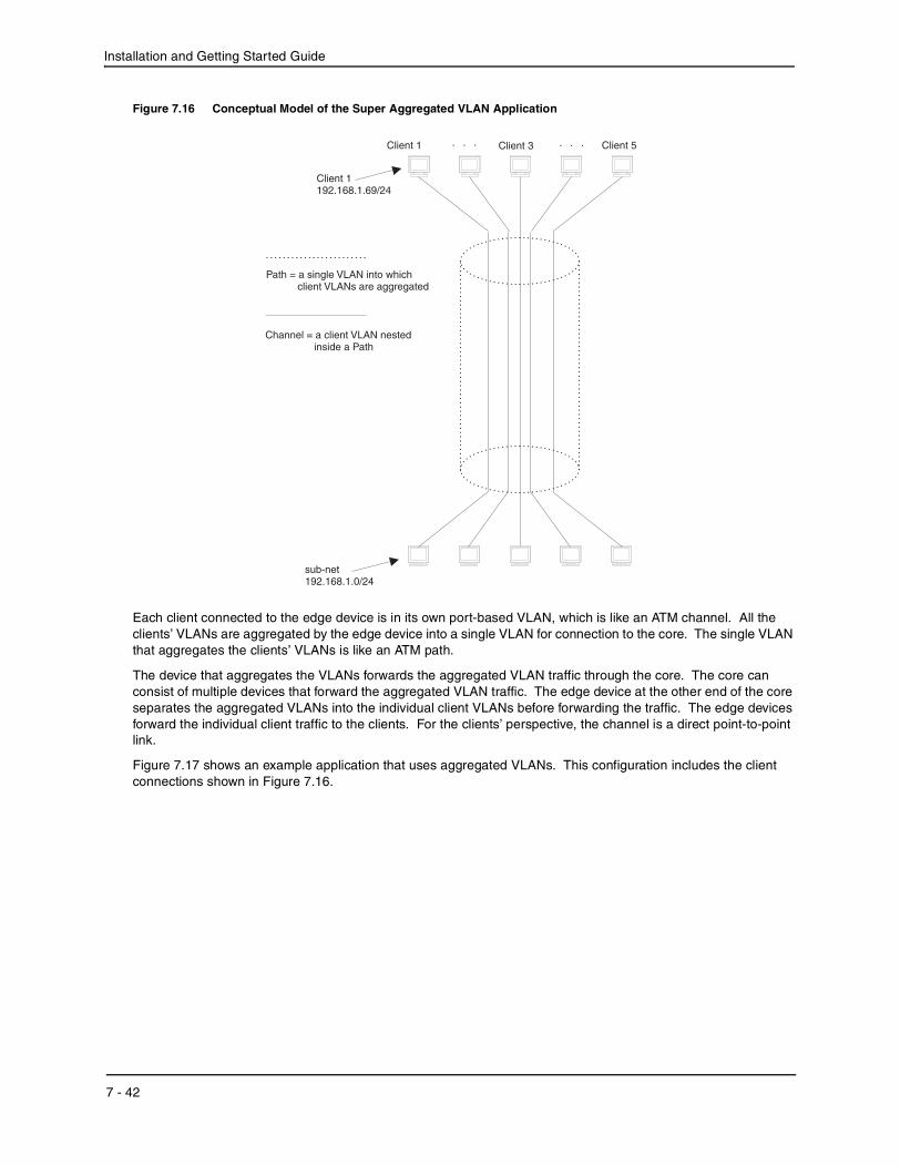
Installation and Getting Started Guide
Figure 7.16 Conceptual Model of the Super Aggregated VLAN Application
Each client connected to the edge device is in its own port-based VLAN, which is like an ATM channel. All the clients’ VLANs are aggregated by the edge device into a single VLAN for connection to the core. The single VLAN that aggregates the clients’ VLANs is like an ATM path.
The device that aggregates the VLANs forwards the aggregated VLAN traffic through the core. The core can consist of multiple devices that forward the aggregated VLAN traffic. The edge device at the other end of the core separates the aggregated VLANs into the individual client VLANs before forwarding the traffic. The edge devices forward the individual client traffic to the clients. For the clients’ perspective, the channel is a direct point-to-point link.
Figure 7.17 shows an example application that uses aggregated VLANs. This configuration includes the client connections shown in Figure 7.16.
Channel = a client VLAN nestedinside a Path
Client 5Client 3. . . . . .Client 1
sub-net192.168.1.0/24
Path = a single VLAN into whichclient VLANs are aggregated
Client 1192.168.1.69/24
7 - 42
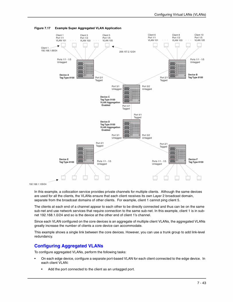
Configuring Virtual LANs (VLANs)
Figure 7.17 Example Super Aggregated VLAN Application
In this example, a collocation service provides private channels for multiple clients. Although the same devices are used for all the clients, the VLANs ensure that each client receives its own Layer 2 broadcast domain, separate from the broadcast domains of other clients. For example, client 1 cannot ping client 5.
The clients at each end of a channel appear to each other to be directly connected and thus can be on the same sub-net and use network services that require connection to the same sub-net. In this example, client 1 is in sub-net 192.168.1.0/24 and so is the device at the other end of client 1’s channel.
Since each VLAN configured on the core devices is an aggregate of multiple client VLANs, the aggregated VLANs greatly increase the number of clients a core device can accommodate.
This example shows a single link between the core devices. However, you can use a trunk group to add link-level redundancy.
Configuring Aggregated VLANsTo configure aggregated VLANs, perform the following tasks:
• On each edge device, configure a separate port-based VLAN for each client connected to the edge device. In each client VLAN:
• Add the port connected to the client as an untagged port.
Port 2/1Tagged
Port 3/1Untagged
Port 2/1Tagged
Ports 1/1 - 1/5Untagged
Ports 1/1 - 1/5Untagged
Port 4/1Tagged
Port 3/2Untagged
Port 3/1Untagged
Port 3/2Untagged
Port 4/1Tagged
Port 2/1Tagged
Device DTag Type 9100VLAN AggregationEnabled
Ports 1/1 - 1/5Untagged
Client 10Port 1/5VLAN 105
Client 8Port 1/3VLAN 103. . . . . .
Port 2/1Tagged
Device ATag Type 8100
Device ETag Type 8100
Device BTag Type 8100
Device FTag Type 8100
Device CTag Type 9100VLAN AggregationEnabled
192.168.1.129/24
Client 6Port 1/1VLAN 101
Client 5Port 1/5VLAN 105
Client 3Port 1/3VLAN 103. . . . . .
Client 1Port 1/1VLAN 101
Ports 1/1 - 1/5Untagged
209.157.2.12/24
Client 1192.168.1.69/24
7 - 43
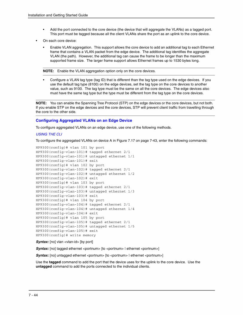
Installation and Getting Started Guide
• Add the port connected to the core device (the device that will aggregate the VLANs) as a tagged port. This port must be tagged because all the client VLANs share the port as an uplink to the core device.
• On each core device:
• Enable VLAN aggregation. This support allows the core device to add an additional tag to each Ethernet frame that contains a VLAN packet from the edge device. The additional tag identifies the aggregate VLAN (the path). However, the additional tag can cause the frame to be longer than the maximum supported frame size. The larger frame support allows Ethernet frames up to 1530 bytes long.
NOTE: Enable the VLAN aggregation option only on the core devices.
• Configure a VLAN tag type (tag ID) that is different than the tag type used on the edge devices. If you use the default tag type (8100) on the edge devices, set the tag type on the core devices to another value, such as 9100. The tag type must be the same on all the core devices. The edge devices also must have the same tag type but the type must be different from the tag type on the core devices.
NOTE: You can enable the Spanning Tree Protocol (STP) on the edge devices or the core devices, but not both. If you enable STP on the edge devices and the core devices, STP will prevent client traffic from travelling through the core to the other side.
Configuring Aggregated VLANs on an Edge Device
To configure aggregated VLANs on an edge device, use one of the following methods.
USING THE CLI
To configure the aggregated VLANs on device A in Figure 7.17 on page 7-43, enter the following commands:
HP9300(config)# vlan 101 by portHP9300(config-vlan-101)# tagged ethernet 2/1HP9300(config-vlan-101)# untagged ethernet 1/1HP9300(config-vlan-101)# exitHP9300(config)# vlan 102 by portHP9300(config-vlan-102)# tagged ethernet 2/1HP9300(config-vlan-102)# untagged ethernet 1/2HP9300(config-vlan-102)# exitHP9300(config)# vlan 103 by portHP9300(config-vlan-103)# tagged ethernet 2/1HP9300(config-vlan-103)# untagged ethernet 1/3HP9300(config-vlan-103)# exitHP9300(config)# vlan 104 by portHP9300(config-vlan-104)# tagged ethernet 2/1HP9300(config-vlan-104)# untagged ethernet 1/4HP9300(config-vlan-104)# exitHP9300(config)# vlan 105 by portHP9300(config-vlan-105)# tagged ethernet 2/1HP9300(config-vlan-105)# untagged ethernet 1/5HP9300(config-vlan-105)# exitHP9300(config)# write memory
Syntax: [no] vlan <vlan-id> [by port]
Syntax: [no] tagged ethernet <portnum> [to <portnum> | ethernet <portnum>]
Syntax: [no] untagged ethernet <portnum> [to <portnum> | ethernet <portnum>]
Use the tagged command to add the port that the device uses for the uplink to the core device. Use the untagged command to add the ports connected to the individual clients.
7 - 44

Configuring Virtual LANs (VLANs)
USING THE WEB MANAGEMENT INTERFACE
You cannot enable VLAN aggregation using the Web management interface. The other options you need for configuring Aggregated VLANs are present in earlier software releases and are supported in the Web management interface.
Configuring Aggregated VLANs on a Core Device
To configure aggregated VLANs on a core device, use one of the following methods.
USING THE CLI
To configure the aggregated VLANs on device C in Figure 7.17 on page 7-43, enter the following commands:
HP9300(config)# tag-type 9100HP9300(config)# aggregated-vlanHP9300(config)# vlan 101 by portHP9300(config-vlan-101)# tagged ethernet 4/1HP9300(config-vlan-101)# untagged ethernet 3/1HP9300(config-vlan-101)# exitHP9300(config)# vlan 102 by portHP9300(config-vlan-102)# tagged ethernet 4/1HP9300(config-vlan-102)# untagged ethernet 3/2HP9300(config-vlan-102)# exitHP9300(config)# write memory
Syntax: [no] tag-type <num>
Syntax: [no] aggregated-vlan
The <num> parameter specifies the tag type can be a hexadecimal value from 0 – ffff. The default is 8100.
USING THE WEB MANAGEMENT INTERFACE
You cannot enable VLAN aggregation using the Web management interface.
Verifying the Configuration
You can verify the VLAN, VLAN aggregation option, and tag configuration by viewing the running-config. To display the running-config, enter the show running-config command from any CLI prompt. After you save the configuration changes to the startup-config, you also can display the settings in that file by entering the show configuration command from any CLI prompt.
Complete CLI ExamplesThe following sections show all the Aggregated VLAN configuration commands on the devices in Figure 7.17 on page 7-43.
NOTE: In these examples, the configurations of the edge devices (A, B, E, and F) are identical. The configurations of the core devices (C and D) also are identical. The aggregated VLAN configurations of the edge and core devices on one side must be symmetrical (in fact, a mirror image) to the configurations of the devices on the other side. For simplicity, the example in Figure 7.17 on page 7-43 is symmetrical in terms of the port numbers. This allows the configurations for both sides of the link to be the same. If your configuration does not use symmetrically arranged port numbers, the configurations should not be identical but must use the correct port numbers.
Commands for Device A
HP9300A(config)# vlan 101 by portHP9300A(config-vlan-101)# tagged ethernet 2/1HP9300A(config-vlan-101)# untagged ethernet 1/1HP9300A(config-vlan-101)# exitHP9300A(config)# vlan 102 by portHP9300A(config-vlan-102)# tagged ethernet 2/1HP9300A(config-vlan-102)# untagged ethernet 1/2
7 - 45

Installation and Getting Started Guide
HP9300A(config-vlan-102)# exitHP9300A(config)# vlan 103 by portHP9300A(config-vlan-103)# tagged ethernet 2/1HP9300A(config-vlan-103)# untagged ethernet 1/3HP9300A(config-vlan-103)# exitHP9300A(config)# vlan 104 by portHP9300A(config-vlan-104)# tagged ethernet 2/1HP9300A(config-vlan-104)# untagged ethernet 1/4HP9300A(config-vlan-104)# exitHP9300A(config)# vlan 105 by portHP9300A(config-vlan-105)# tagged ethernet 2/1HP9300A(config-vlan-105)# untagged ethernet 1/5HP9300A(config-vlan-105)# exitHP9300A(config)# write memory
Commands for Device B
The commands for configuring device B are identical to the commands for configuring device A. Notice that you can use the same channel VLAN numbers on each device. The devices that aggregate the VLANs into a path can distinguish between the identically named channel VLANs based on the ID of the path VLAN.
HP9300B(config)# vlan 101 by portHP9300B(config-vlan-101)# tagged ethernet 2/1HP9300B(config-vlan-101)# untagged ethernet 1/1HP9300B(config-vlan-101)# exitHP9300B(config)# vlan 102 by portHP9300B(config-vlan-102)# tagged ethernet 2/1HP9300B(config-vlan-102)# untagged ethernet 1/2HP9300B(config-vlan-102)# exitHP9300B(config)# vlan 103 by portHP9300B(config-vlan-103)# tagged ethernet 2/1HP9300B(config-vlan-103)# untagged ethernet 1/3HP9300B(config-vlan-103)# exitHP9300B(config)# vlan 104 by portHP9300B(config-vlan-104)# tagged ethernet 2/1HP9300B(config-vlan-104)# untagged ethernet 1/4HP9300B(config-vlan-104)# exitHP9300B(config)# vlan 105 by portHP9300B(config-vlan-105)# tagged ethernet 2/1HP9300B(config-vlan-105)# untagged ethernet 1/5HP9300B(config-vlan-105)# exitHP9300B(config)# write memory
Commands for Device C
Since device C is aggregating channel VLANs from devices A and B into a single path, you need to change the tag type and enable VLAN aggregation.
HP9300C(config)# tag-type 9100HP9300C(config)# aggregated-vlanHP9300C(config)# vlan 101 by portHP9300C(config-vlan-101)# tagged ethernet 4/1HP9300C(config-vlan-101)# untagged ethernet 3/1HP9300C(config-vlan-101)# exitHP9300C(config)# vlan 102 by portHP9300C(config-vlan-102)# tagged ethernet 4/1HP9300C(config-vlan-102)# untagged ethernet 3/2HP9300C(config-vlan-102)# exitHP9300C(config)# write memory
7 - 46
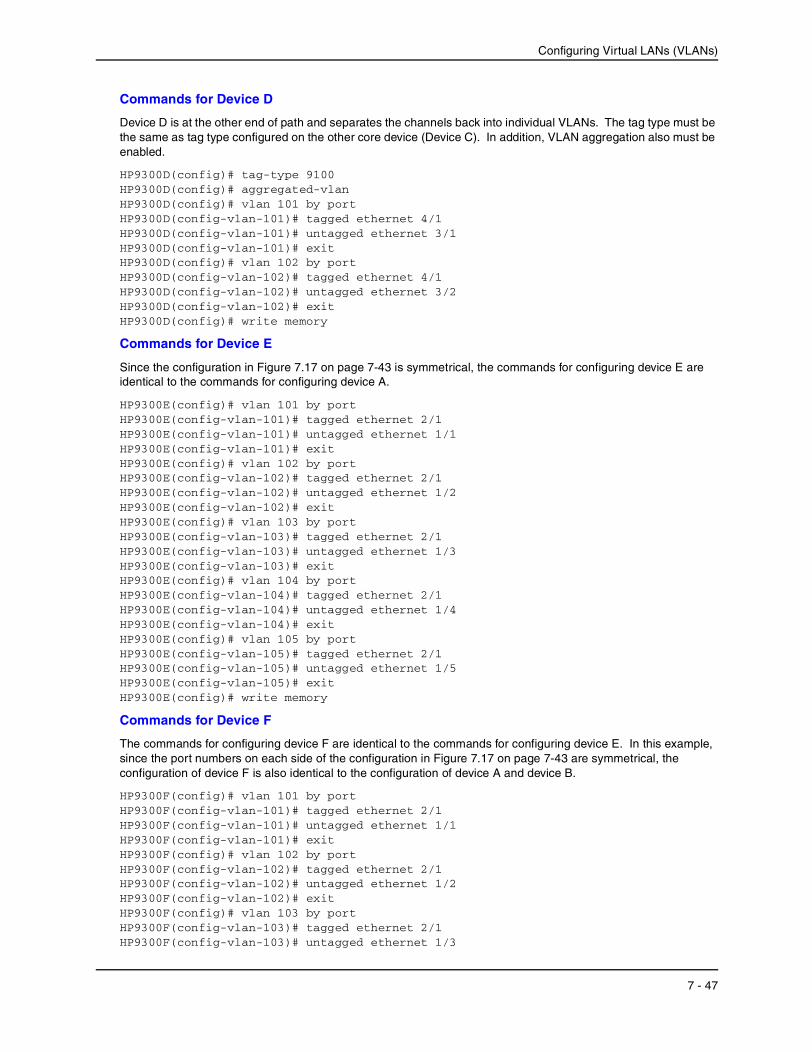
Configuring Virtual LANs (VLANs)
Commands for Device D
Device D is at the other end of path and separates the channels back into individual VLANs. The tag type must be the same as tag type configured on the other core device (Device C). In addition, VLAN aggregation also must be enabled.
HP9300D(config)# tag-type 9100HP9300D(config)# aggregated-vlanHP9300D(config)# vlan 101 by portHP9300D(config-vlan-101)# tagged ethernet 4/1HP9300D(config-vlan-101)# untagged ethernet 3/1HP9300D(config-vlan-101)# exitHP9300D(config)# vlan 102 by portHP9300D(config-vlan-102)# tagged ethernet 4/1HP9300D(config-vlan-102)# untagged ethernet 3/2HP9300D(config-vlan-102)# exitHP9300D(config)# write memory
Commands for Device E
Since the configuration in Figure 7.17 on page 7-43 is symmetrical, the commands for configuring device E are identical to the commands for configuring device A.
HP9300E(config)# vlan 101 by portHP9300E(config-vlan-101)# tagged ethernet 2/1HP9300E(config-vlan-101)# untagged ethernet 1/1HP9300E(config-vlan-101)# exitHP9300E(config)# vlan 102 by portHP9300E(config-vlan-102)# tagged ethernet 2/1HP9300E(config-vlan-102)# untagged ethernet 1/2HP9300E(config-vlan-102)# exitHP9300E(config)# vlan 103 by portHP9300E(config-vlan-103)# tagged ethernet 2/1HP9300E(config-vlan-103)# untagged ethernet 1/3HP9300E(config-vlan-103)# exitHP9300E(config)# vlan 104 by portHP9300E(config-vlan-104)# tagged ethernet 2/1HP9300E(config-vlan-104)# untagged ethernet 1/4HP9300E(config-vlan-104)# exitHP9300E(config)# vlan 105 by portHP9300E(config-vlan-105)# tagged ethernet 2/1HP9300E(config-vlan-105)# untagged ethernet 1/5HP9300E(config-vlan-105)# exitHP9300E(config)# write memory
Commands for Device F
The commands for configuring device F are identical to the commands for configuring device E. In this example, since the port numbers on each side of the configuration in Figure 7.17 on page 7-43 are symmetrical, the configuration of device F is also identical to the configuration of device A and device B.
HP9300F(config)# vlan 101 by portHP9300F(config-vlan-101)# tagged ethernet 2/1HP9300F(config-vlan-101)# untagged ethernet 1/1HP9300F(config-vlan-101)# exitHP9300F(config)# vlan 102 by portHP9300F(config-vlan-102)# tagged ethernet 2/1HP9300F(config-vlan-102)# untagged ethernet 1/2HP9300F(config-vlan-102)# exitHP9300F(config)# vlan 103 by portHP9300F(config-vlan-103)# tagged ethernet 2/1HP9300F(config-vlan-103)# untagged ethernet 1/3
7 - 47
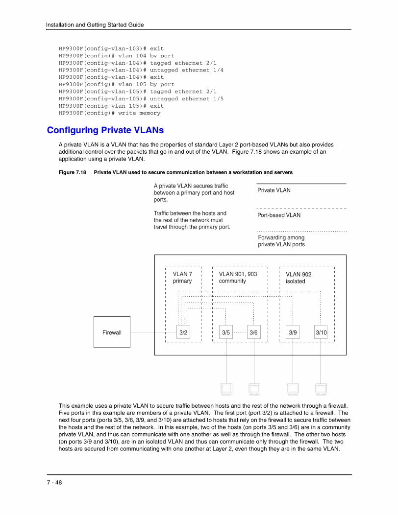
Installation and Getting Started Guide
HP9300F(config-vlan-103)# exitHP9300F(config)# vlan 104 by portHP9300F(config-vlan-104)# tagged ethernet 2/1HP9300F(config-vlan-104)# untagged ethernet 1/4HP9300F(config-vlan-104)# exitHP9300F(config)# vlan 105 by portHP9300F(config-vlan-105)# tagged ethernet 2/1HP9300F(config-vlan-105)# untagged ethernet 1/5HP9300F(config-vlan-105)# exitHP9300F(config)# write memory
Configuring Private VLANsA private VLAN is a VLAN that has the properties of standard Layer 2 port-based VLANs but also provides additional control over the packets that go in and out of the VLAN. Figure 7.18 shows an example of an application using a private VLAN.
Figure 7.18 Private VLAN used to secure communication between a workstation and servers
This example uses a private VLAN to secure traffic between hosts and the rest of the network through a firewall. Five ports in this example are members of a private VLAN. The first port (port 3/2) is attached to a firewall. The next four ports (ports 3/5, 3/6, 3/9, and 3/10) are attached to hosts that rely on the firewall to secure traffic between the hosts and the rest of the network. In this example, two of the hosts (on ports 3/5 and 3/6) are in a community private VLAN, and thus can communicate with one another as well as through the firewall. The other two hosts (on ports 3/9 and 3/10), are in an isolated VLAN and thus can communicate only through the firewall. The two hosts are secured from communicating with one another at Layer 2, even though they are in the same VLAN.
Private VLAN
Forwarding amongprivate VLAN ports
VLAN 7primary
3/9 3/10
VLAN 902isolated
VLAN 901, 903community
3/2
A private VLAN secures trafficbetween a primary port and hostports.
Traffic between the hosts andthe rest of the network musttravel through the primary port.
Port-based VLAN
3/5 3/6Firewall
7 - 48
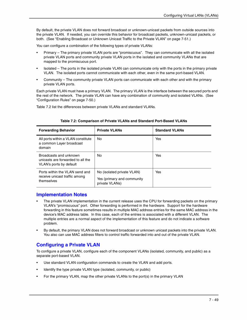
Configuring Virtual LANs (VLANs)
By default, the private VLAN does not forward broadcast or unknown-unicast packets from outside sources into the private VLAN. If needed, you can override this behavior for broadcast packets, unknown-unicast packets, or both. (See “Enabling Broadcast or Unknown Unicast Traffic to the Private VLAN” on page 7-51.)
You can configure a combination of the following types of private VLANs:
• Primary – The primary private VLAN ports are “promiscuous”. They can communicate with all the isolated private VLAN ports and community private VLAN ports in the isolated and community VLANs that are mapped to the promiscuous port.
• Isolated – The ports in the isolated private VLAN can communicate only with the ports in the primary private VLAN. The isolated ports cannot communicate with each other, even in the same port-based VLAN.
• Community – The community private VLAN ports can communicate with each other and with the primary private VLAN ports.
Each private VLAN must have a primary VLAN. The primary VLAN is the interface between the secured ports and the rest of the network. The private VLAN can have any combination of community and isolated VLANs. (See “Configuration Rules” on page 7-50.)
Table 7.2 list the differences between private VLANs and standard VLANs.
Implementation Notes• The private VLAN implementation in the current release uses the CPU for forwarding packets on the primary
VLAN’s “promiscuous” port. Other forwarding is performed in the hardware. Support for the hardware forwarding in this feature sometimes results in multiple MAC address entries for the same MAC address in the device’s MAC address table. In this case, each of the entries is associated with a different VLAN. The multiple entries are a normal aspect of the implementation of this feature and do not indicate a software problem.
• By default, the primary VLAN does not forward broadcast or unknown unicast packets into the private VLAN. You also can use MAC address filters to control traffic forwarded into and out of the private VLAN.
Configuring a Private VLANTo configure a private VLAN, configure each of the component VLANs (isolated, community, and public) as a separate port-based VLAN.
• Use standard VLAN configuration commands to create the VLAN and add ports.
• Identify the type private VLAN type (isolated, community, or public)
• For the primary VLAN, map the other private VLANs to the port(s) in the primary VLAN
Table 7.2: Comparison of Private VLANs and Standard Port-Based VLANs
Forwarding Behavior Private VLANs Standard VLANs
All ports within a VLAN constitute a common Layer broadcast domain
No Yes
Broadcasts and unknown unicasts are forwarded to all the VLAN’s ports by default
No Yes
Ports within the VLAN send and receive unicast traffic among themselves
No (isolated private VLAN)
Yes (primary and community private VLANs)
Yes
7 - 49
Installation and Getting Started Guide
Configuration Rules
• You can use 10/100 and Gigabit Ethernet ports in a private VLAN.
• You cannot configure any of the ports in a private VLAN to be members of a trunk group.
• You cannot share a port between a private VLAN and a standard port-based VLAN or protocol VLAN. You can configure private VLANs and standard port-based VLANs and protocol VLANs on the same device, but a port cannot be a member of both a private VLAN and a port-based VLAN or protocol VLAN.
NOTE: Although a private VLAN resides within a port-based VLAN, the VLAN is considered to be exclusively a private VLAN, not a port-based VLAN.
• You cannot use the private VLAN feature and the dual-mode VLAN port feature on the same device.
• The Spanning Tree Protocol (STP) is independent of this feature, and can be enabled or disabled in the individual port-based VLANs. However, private VLANs are not supported with single-instance STP (“single span”).
• You can configure only one private VLAN within a given port-based VLAN. Thus, you must configure a separate port-based VLAN for each private VLAN.
• Each private VLAN can have only one primary VLAN.
• Each private VLAN can have multiple isolated or community VLANs. You can use any combination of isolated or community VLANs with the primary VLAN. You do not need to use both isolated and community VLANs in the private VLAN.
• You can configure the primary VLAN before or after you configure the community or isolated VLANs. You are not required to configure a specific type of private VLAN before you can configure the other types.
• The ports in all three types of private VLANs can be tagged or untagged.
NOTE: If the port in the primary VLAN is tagged, you must add the port as a tagged port to each of the isolated and community VLANs. If the port in the primary VLAN is untagged, you do not need to add the port to the isolated and community VLANs.
• The primary VLAN has only one active port. The primary VLAN can have more than one port, but only the lowest-numbered available port is active. The other ports provide redundancy.
• You cannot configure the default VLAN (VLAN 1) as a private VLAN.
Configuring an Isolated or Community Private VLAN
To configure an isolated or a community private VLAN, use the following CLI methods.
USING THE CLI
To configure a community private VLAN, enter commands such as the following:
HP9300(config)# vlan 901HP9300(config-vlan-901)# tagged ethernet 3/5 to 3/6HP9300(config-vlan-901)# pvlan type community
These commands create port-based VLAN 901, add ports 3/5 and 3/6 to the VLAN as tagged ports, then specify that the VLAN is a community private VLAN.
Syntax: tagged ethernet <portnum> [to <portnum> | ethernet <portnum>]
Syntax: [no] pvlan type community | isolated | primary
The tagged or untagged command adds the ports to the VLAN. For syntax information and more examples, see the “Configuring Virtual LANs (VLANs)” chapter of the Installation and Getting Started Guide.
The pvlan type command specifies that this port-based VLAN is a private VLAN.
• community – specifies that the VLAN is a community private VLAN. The ports can communicate with the
7 - 50
Configuring Virtual LANs (VLANs)
active port in the primary VLAN and with each other.
• isolated – specifies that the VLAN is a community private VLAN. The ports can communicate only with the active port in the primary VLAN. They cannot communicate with one another or with any other ports.
• primary – specifies that the VLAN is a primary private VLAN. See “Configuring the Primary VLAN” .
Configuring the Primary VLAN
Use the following CLI method to configure the primary VLAN.
NOTE: The primary private VLAN has only one active port. If you configure the VLAN to have more than one port, the lowest-numbered port is the active one. The additional ports provide redundancy. If the active port becomes unavailable, the lowest-numbered available port becomes the active port for the VLAN.
USING THE CLI
To configure a primary private VLAN, enter commands such as the following:
HP9300(config)# vlan 7HP9300(config-vlan-7)# untagged ethernet 3/2HP9300(config-vlan-7)# pvlan type primaryHP9300(config-vlan-7)# pvlan mapping 901 ethernet 3/2
These commands create port-based VLAN 7, add port 3/2 as an untagged port, identify the VLAN as the primary VLAN in a private VLAN, and map the other private VLANs to the port(s) in this VLAN.
Syntax: untagged ethernet <portnum> [to <portnum> | ethernet <portnum>]
Syntax: [no] pvlan type community | isolated | primary
Syntax: [no] pvlan mapping <vlan-id> ethernet <portnum>
The tagged or untagged command adds the port(s) to the VLAN. For syntax information and more examples, see the “Configuring Virtual LANs (VLANs)” chapter of the Installation and Getting Started Guide.
NOTE: You can add the port as a tagged port if needed. If you add the port as a tagged port, you must also add the port as a tagged port to the isolated and community VLANs. See “CLI Example for Figure 7.18” on page 7-52.
The pvlan type command specifies that this port-based VLAN is a private VLAN. Specify primary as the type.
The pvlan mapping command identifies the other private VLANs for which this VLAN is the primary. The command also specifies the primary VLAN ports to which you are mapping the other private VLANs.
• The <vlan-id> parameter specifies another private VLAN. The other private VLAN you want to specify must already be configured.
• The ethernet <portnum> parameter specifies the primary VLAN port to which you are mapping all the ports in the other private VLAN (the one specified by <vlan-id>).
Enabling Broadcast or Unknown Unicast Traffic to the Private VLANTo enhance private VLAN security, the primary private VLAN does not forward broadcast or unknown unicast packets to its community and isolated VLANs. For example, if port 3/2 in Figure 7.18 on page 7-48 receives a broadcast packet from the firewall, the port does not forward the packet to the other private VLAN ports (3/5, 3/6, 3/9, and 3/10).
This forwarding restriction does not apply to traffic from the private VLAN. The primary port does forward broadcast and unknown unicast packets that are received from the isolated and community VLANs. For example, if the host on port 3/9 sends an unknown unicast packet, port 3/2 forwards the packet to the firewall.
If you want to remove the forwarding restriction, you can enable the primary port to forward broadcast or unknown unicast traffic, if desired, using the following CLI method. You can enable or disable forwarding of broadcast or unknown unicast packets separately.
7 - 51
Installation and Getting Started Guide
NOTE: You also can use MAC address filters to control the traffic forwarded into and out of the private VLAN.
USING THE CLI
To configure the ports in the primary VLAN to forward broadcast or unknown unicast traffic received from sources outside the private VLAN, enter the following commands at the global CONFIG level of the CLI:
HP9300(config)# pvlan-preference broadcast floodHP9300(config)# pvlan-preference unknown-unicast flood
These commands enable forwarding of broadcast and unknown-unicast packets to ports within the private VLAN. To again disable forwarding, enter a command such as the following:
HP9300(config)# no pvlan-preference broadcast flood
This command disables forwarding of broadcast packets within the private VLAN.
Syntax: [no] pvlan-preference broadcast | unknown-unicast flood
CLI Example for Figure 7.18To configure the private VLANs shown in Figure 7.18 on page 7-48, enter the following commands:
HP9300(config)# vlan 901HP9300(config-vlan-901)# tagged ethernet 3/5 to 3/6HP9300(config-vlan-901)# pvlan type communityHP9300(config-vlan-901)# exitHP9300(config)# vlan 902HP9300(config-vlan-902)# tagged ethernet 3/9 to 3/10HP9300(config-vlan-902)# pvlan type isolatedHP9300(config-vlan-902)# exitHP9300(config)# vlan 903HP9300(config-vlan-903)# tagged ethernet 3/5 to 3/6HP9300(config-vlan-903)# pvlan type communityHP9300(config-vlan-903)# exitHP9300(config)# vlan 7HP9300(config-vlan-7)# untagged ethernet 3/2HP9300(config-vlan-7)# pvlan type primaryHP9300(config-vlan-7)# pvlan mapping 901 ethernet 3/2HP9300(config-vlan-7)# pvlan mapping 902 ethernet 3/2HP9300(config-vlan-7)# pvlan mapping 903 ethernet 3/2
This example assumes that the port in the primary private VLAN is untagged. If the port in the primary VLAN is tagged, you must add the port as a tagged port to the isolated and community VLANs, as in the following example:
HP9300(config)# vlan 901HP9300(config-vlan-901)# tagged ethernet 3/5 to 3/6HP9300(config-vlan-901)# tagged ethernet 3/2HP9300(config-vlan-901)# pvlan type communityHP9300(config-vlan-901)# exitHP9300(config)# vlan 902HP9300(config-vlan-902)# tagged ethernet 3/9 to 3/10HP9300(config-vlan-902)# tagged ethernet 3/2HP9300(config-vlan-902)# pvlan type isolatedHP9300(config-vlan-902)# exitHP9300(config)# vlan 903HP9300(config-vlan-903)# tagged ethernet 3/5 to 3/6HP9300(config-vlan-903)# tagged ethernet 3/2HP9300(config-vlan-903)# pvlan type communityHP9300(config-vlan-903)# exitHP9300(config)# vlan 7HP9300(config-vlan-7)# tagged ethernet 3/2
7 - 52
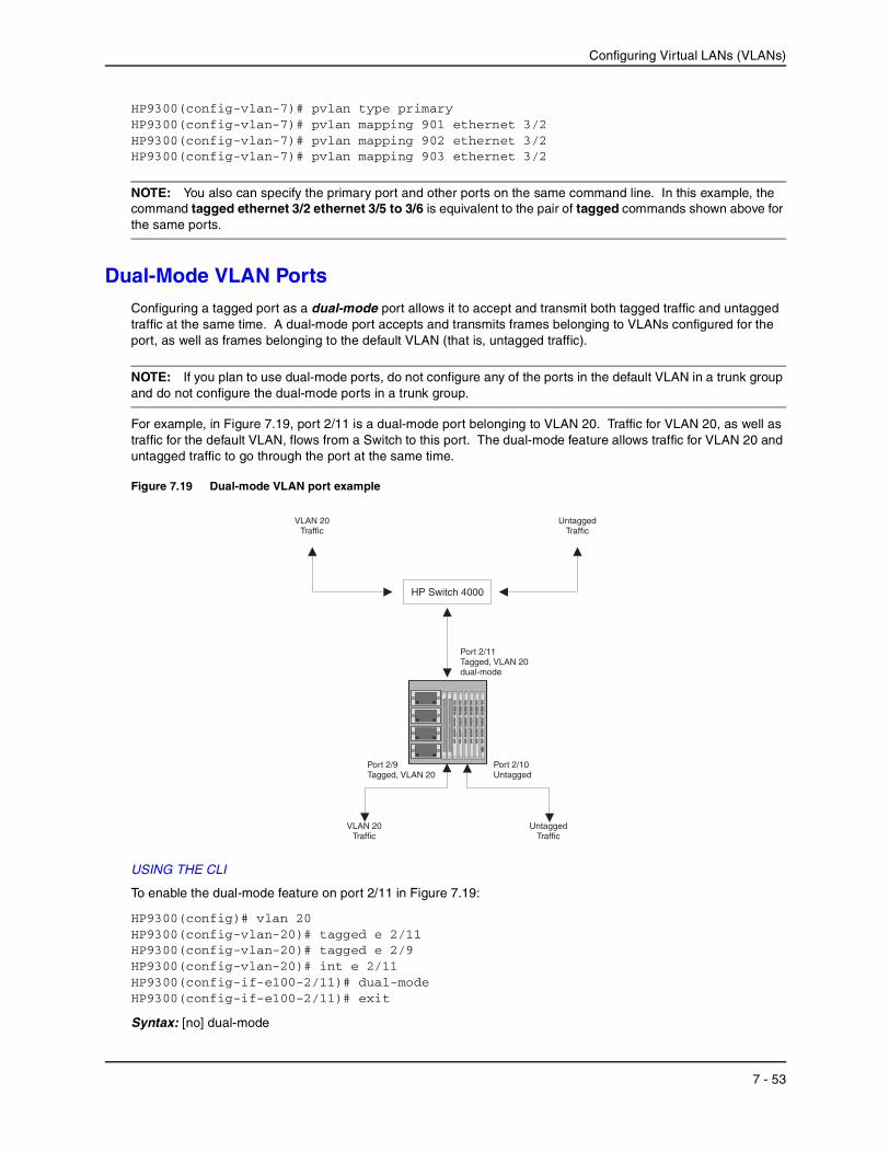
Configuring Virtual LANs (VLANs)
HP9300(config-vlan-7)# pvlan type primaryHP9300(config-vlan-7)# pvlan mapping 901 ethernet 3/2HP9300(config-vlan-7)# pvlan mapping 902 ethernet 3/2HP9300(config-vlan-7)# pvlan mapping 903 ethernet 3/2
NOTE: You also can specify the primary port and other ports on the same command line. In this example, the command tagged ethernet 3/2 ethernet 3/5 to 3/6 is equivalent to the pair of tagged commands shown above for the same ports.
Dual-Mode VLAN PortsConfiguring a tagged port as a dual-mode port allows it to accept and transmit both tagged traffic and untagged traffic at the same time. A dual-mode port accepts and transmits frames belonging to VLANs configured for the port, as well as frames belonging to the default VLAN (that is, untagged traffic).
NOTE: If you plan to use dual-mode ports, do not configure any of the ports in the default VLAN in a trunk group and do not configure the dual-mode ports in a trunk group.
For example, in Figure 7.19, port 2/11 is a dual-mode port belonging to VLAN 20. Traffic for VLAN 20, as well as traffic for the default VLAN, flows from a Switch to this port. The dual-mode feature allows traffic for VLAN 20 and untagged traffic to go through the port at the same time.
Figure 7.19 Dual-mode VLAN port example
USING THE CLI
To enable the dual-mode feature on port 2/11 in Figure 7.19:
HP9300(config)# vlan 20HP9300(config-vlan-20)# tagged e 2/11HP9300(config-vlan-20)# tagged e 2/9HP9300(config-vlan-20)# int e 2/11HP9300(config-if-e100-2/11)# dual-modeHP9300(config-if-e100-2/11)# exit
Syntax: [no] dual-mode
HP Switch 4000
Port 2/11Tagged, VLAN 20dual-mode
Port 2/9Tagged, VLAN 20
Port 2/10Untagged
UntaggedTraffic
VLAN 20Traffic
UntaggedTraffic
VLAN 20Traffic
7 - 53
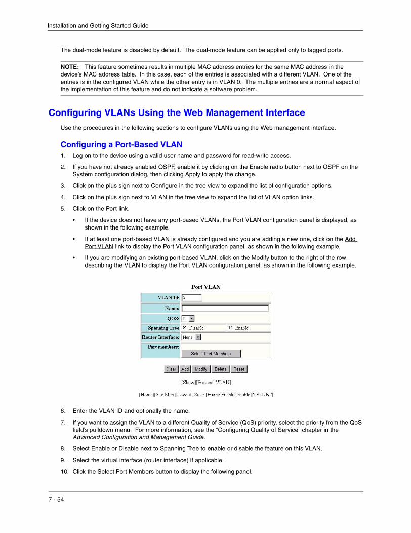
Installation and Getting Started Guide
The dual-mode feature is disabled by default. The dual-mode feature can be applied only to tagged ports.
NOTE: This feature sometimes results in multiple MAC address entries for the same MAC address in the device’s MAC address table. In this case, each of the entries is associated with a different VLAN. One of the entries is in the configured VLAN while the other entry is in VLAN 0. The multiple entries are a normal aspect of the implementation of this feature and do not indicate a software problem.
Configuring VLANs Using the Web Management InterfaceUse the procedures in the following sections to configure VLANs using the Web management interface.
Configuring a Port-Based VLAN1. Log on to the device using a valid user name and password for read-write access.
2. If you have not already enabled OSPF, enable it by clicking on the Enable radio button next to OSPF on the System configuration dialog, then clicking Apply to apply the change.
3. Click on the plus sign next to Configure in the tree view to expand the list of configuration options.
4. Click on the plus sign next to VLAN in the tree view to expand the list of VLAN option links.
5. Click on the Port link.
• If the device does not have any port-based VLANs, the Port VLAN configuration panel is displayed, as shown in the following example.
• If at least one port-based VLAN is already configured and you are adding a new one, click on the Add Port VLAN link to display the Port VLAN configuration panel, as shown in the following example.
• If you are modifying an existing port-based VLAN, click on the Modify button to the right of the row describing the VLAN to display the Port VLAN configuration panel, as shown in the following example.
6. Enter the VLAN ID and optionally the name.
7. If you want to assign the VLAN to a different Quality of Service (QoS) priority, select the priority from the QoS field’s pulldown menu. For more information, see the “Configuring Quality of Service” chapter in the Advanced Configuration and Management Guide.
8. Select Enable or Disable next to Spanning Tree to enable or disable the feature on this VLAN.
9. Select the virtual interface (router interface) if applicable.
10. Click the Select Port Members button to display the following panel.
7 - 54

Configuring Virtual LANs (VLANs)
11. Select the ports you are placing in the VLAN. To select a row, click on the checkbox next to the row number, then click on the Select Row button.
NOTE: Ports highlighted in grey are members of a trunk group. The port right before the grey ports is the master port for that trunk group.
12. When you finish selecting the ports, click on the Continue button to return to the Port VLAN configuration dialog.
13. Click the Add button (to add a new VLAN) or the Modify button (if you are modifying an existing VLAN) to save the change to the device’s running-config file.
14. Select the Save link at the bottom of the dialog, then select Yes when prompted to save the configuration change to the startup-config file on the device’s flash memory.
Configuring a Protocol-Based VLANThis procedure describes how to configure a protocol-based VLAN. To configure an IP sub-net VLAN, IPX network VLAN, or AppleTalk cable VLAN, se the sections following this one.
1. Log on to the device using a valid user name and password for read-write access.
2. Click on the plus sign next to Configure in the tree view to expand the list of configuration options.
3. Click on the plus sign next to VLAN in the tree view to expand the list of VLAN option links.
4. Click on the Protocol link.
• If the device does not have any protocol VLANs, the Protocol VLAN configuration panel is displayed, as shown in the following example.
• If at least one protocol VLAN is already configured and you are adding a new one, click on the Protocol link to display the Protocol VLAN configuration panel.
• If you are modifying an existing protocol VLAN, click on the Modify button to the right of the row describing the VLAN to display the configuration panel for the type of VLAN you are modifying. The following example shows the Protocol VLAN configuration dialog, used for configuring a protocol VLAN (not an IP sub-net, IPX network, or AppleTalk cable VLAN).
7 - 55

Installation and Getting Started Guide
5. Enter the VLAN ID that will contain the protocol VLAN in the VLAN ID field.
6. Enter a name for the VLAN in the Protocol_VLAN_Name field.
7. Select the virtual interface from the Router_Interface pulldown list if you configured a virtual interface for routing into and out of the VLAN.
8. Select the protocol type.
9. Specify the port that are members for the VLAN:
• Select Dynamic Port if you want the port membership to be dynamic. For information, see “Dynamic Ports” on page 7-9.
• Click the Change Static Members button if you want to configure static ports. For information, see “Static Ports” on page 7-10.
• Click the Change Exclude Members button if you want to explicitly exclude some ports. For information, see “Excluded Ports” on page 7-10.
NOTE: All the ports must be members of the port-based VLAN that contains this IP sub-net VLAN. See “Layer 3 Protocol-Based VLANs” on page 7-3.
10. Click the Add button (if you are adding a new VLAN) or the Modify button (if you are modifying an existing VLAN) to save the change to the device’s running-config file.
11. Select the Save link at the bottom of the dialog. Select Yes when prompted to save the configuration change to the startup-config file on the device’s flash memory.
Configuring an IP Sub-Net VLAN1. Log on to the device using a valid user name and password for read-write access.
2. Click on the plus sign next to Configure in the tree view to expand the list of configuration options.
3. Click on the plus sign next to VLAN in the tree view to expand the list of VLAN option links.
4. Click on the Protocol link.
• If the device does not have any protocol VLANs, the Protocol VLAN configuration panel is displayed, as shown in the following example.
7 - 56

Configuring Virtual LANs (VLANs)
• If at least one protocol VLAN is already configured and you are adding a new one, click on the IP Subnet link to display the IP Sub-net Protocol VLAN configuration panel.
• If you are modifying an existing protocol VLAN, click on the Modify button to the right of the row describing the VLAN to display the configuration panel for the type of VLAN you are modifying. The following example shows the IP Sub-net Protocol VLAN configuration dialog, used for configuring an IP sub-net protocol VLAN (not a protocol, IPX network, or AppleTalk cable VLAN).
5. Enter the VLAN ID that will contain the IP sub-net VLAN in the VLAN ID field.
6. Enter a name for the VLAN in the Protocol_VLAN_Name field.
7. Select the virtual interface from the Router_Interface pulldown list if you configured a virtual interface for routing into and out of the VLAN.
8. Enter the IP address of the VLAN in the IP_Address field.
9. Enter the network mask in the Mask field.
10. Specify the port that are members for the VLAN:
• Select Dynamic Port if you want the port membership to be dynamic. For information, see “Dynamic Ports” on page 7-9.
• Click the Change Static Members button if you want to configure static ports. For information, see “Static Ports” on page 7-10.
• Click the Change Exclude Members button if you want to explicitly exclude some ports. For information, see “Excluded Ports” on page 7-10.
NOTE: All the ports must be members of the port-based VLAN that contains this IP sub-net VLAN. See “Layer 3 Protocol-Based VLANs” on page 7-3.
11. Click the Add button (if you are adding a new VLAN) or the Modify button (if you are modifying an existing VLAN) to save the change to the device’s running-config file.
12. Select the Save link at the bottom of the dialog. Select Yes when prompted to save the configuration change to the startup-config file on the device’s flash memory.
7 - 57

Installation and Getting Started Guide
Configuring an IPX Network VLAN1. Log on to the device using a valid user name and password for read-write access.
2. Click on the plus sign next to Configure in the tree view to expand the list of configuration options.
3. Click on the plus sign next to VLAN in the tree view to expand the list of VLAN option links.
4. Click on the Protocol link.
• If the device does not have any protocol VLANs, the Protocol VLAN configuration panel is displayed, as shown in the following example.
• If at least one protocol VLAN is already configured and you are adding a new one, click on the IPX Network link to display the IP Sub-net Protocol VLAN configuration panel.
• If you are modifying an existing protocol VLAN, click on the Modify button to the right of the row describing the VLAN to display the configuration panel for the type of VLAN you are modifying. The following example shows the IPX Network Protocol VLAN configuration dialog, used for configuring an IPX network protocol VLAN (not a protocol, IP sub-net, or AppleTalk cable VLAN).
5. Enter the VLAN ID that will contain the IPX network VLAN in the VLAN ID field.
6. Enter a name for the VLAN in the Protocol_VLAN_Name field.
7. Select the virtual interface from the Router_Interface pulldown list if you configured a virtual interface for routing into and out of the VLAN.
8. Select the encapsulation type from the Frame_Type field’s pulldown list.
9. Enter the IPX network address of the VLAN in the Network field.
10. Specify the port that are members for the VLAN:
• Select Dynamic Port if you want the port membership to be dynamic. For information, see “Dynamic Ports” on page 7-9.
• Click the Change Static Members button if you want to configure static ports. For information, see “Static Ports” on page 7-10.
• Click the Change Exclude Members button if you want to explicitly exclude some ports. For information, see “Excluded Ports” on page 7-10.
7 - 58

Configuring Virtual LANs (VLANs)
NOTE: All the ports must be members of the port-based VLAN that contains this IPX network VLAN. See “Layer 3 Protocol-Based VLANs” on page 7-3.
11. Click the Add button (if you are adding a new VLAN) or the Modify button (if you are modifying an existing VLAN) to save the change to the device’s running-config file.
12. Select the Save link at the bottom of the dialog. Select Yes when prompted to save the configuration change to the startup-config file on the device’s flash memory.
Configuring an AppleTalk Cable VLAN1. Log on to the device using a valid user name and password for read-write access.
2. Click on the plus sign next to Configure in the tree view to expand the list of configuration options.
3. Click on the plus sign next to VLAN in the tree view to expand the list of VLAN option links.
4. Click on the Protocol link.
• If the device does not have any protocol VLANs, the Protocol VLAN configuration panel is displayed, as shown in the following example.
• If at least one protocol VLAN is already configured and you are adding a new one, click on the AppleTalk Cable link to display the AppleTalk Cable VLAN configuration panel.
• If you are modifying an existing protocol VLAN, click on the Modify button to the right of the row describing the VLAN to display the configuration panel for the type of VLAN you are modifying. The following example shows the AppleTalk Cable VLAN configuration dialog, used for configuring an AppleTalk cable VLAN (not a protocol, IP sub-net, or IPX network VLAN).
5. Enter the VLAN ID that will contain the AppleTalk cable VLAN in the VLAN ID field.
6. Enter a name for the VLAN in the Protocol_VLAN_Name field.
7. Select the virtual interface from the Router_Interface pulldown list if you configured a virtual interface for routing into and out of the VLAN.
8. Select the AppleTalk cable ID from the AppleTalk Cable field’s pulldown list.
7 - 59

Installation and Getting Started Guide
9. Specify the port that are members for the VLAN:
• Select Dynamic Port if you want the port membership to be dynamic. For information, see “Dynamic Ports” on page 7-9.
• Click the Change Static Members button if you want to configure static ports. For information, see “Static Ports” on page 7-10.
• Click the Change Exclude Members button if you want to explicitly exclude some ports. For information, see “Excluded Ports” on page 7-10.
NOTE: All the ports must be members of the port-based VLAN that contains this AppleTalk cable VLAN. See “Layer 3 Protocol-Based VLANs” on page 7-3.
10. Click the Add button (if you are adding a new VLAN) or the Modify button (if you are modifying an existing VLAN) to save the change to the device’s running-config file.
11. Select the Save link at the bottom of the dialog. Select Yes when prompted to save the configuration change to the startup-config file on the device’s flash memory.
Displaying VLAN Information
After you configure the VLANs, you can verify the configuration using the following methods.
NOTE: If a VLAN name begins with “GVRP_VLAN_“, the VLAN was created by the GARP VLAN Registration Protocol (GVRP). If a VLAN name begins with “STATIC_VLAN_“, the VLAN was created by GVRP and then was converted into a statically configured VLAN.
Displaying System-Wide VLAN InformationUse one of the following methods to display VLAN information for all the VLANs configured on the device.
7 - 60
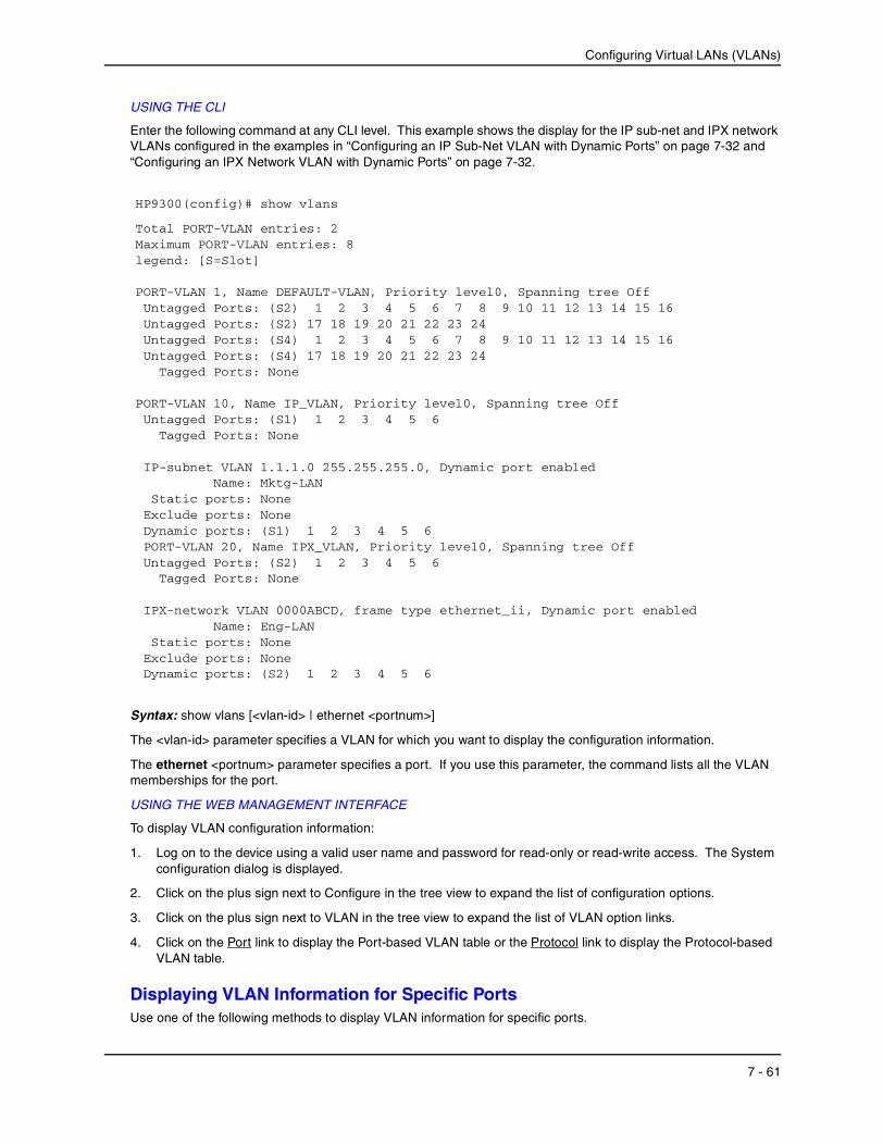
Configuring Virtual LANs (VLANs)
USING THE CLI
Enter the following command at any CLI level. This example shows the display for the IP sub-net and IPX network VLANs configured in the examples in “Configuring an IP Sub-Net VLAN with Dynamic Ports” on page 7-32 and “Configuring an IPX Network VLAN with Dynamic Ports” on page 7-32.
Syntax: show vlans [<vlan-id> | ethernet <portnum>]
The <vlan-id> parameter specifies a VLAN for which you want to display the configuration information.
The ethernet <portnum> parameter specifies a port. If you use this parameter, the command lists all the VLAN memberships for the port.
USING THE WEB MANAGEMENT INTERFACE
To display VLAN configuration information:
1. Log on to the device using a valid user name and password for read-only or read-write access. The System configuration dialog is displayed.
2. Click on the plus sign next to Configure in the tree view to expand the list of configuration options.
3. Click on the plus sign next to VLAN in the tree view to expand the list of VLAN option links.
4. Click on the Port link to display the Port-based VLAN table or the Protocol link to display the Protocol-based VLAN table.
Displaying VLAN Information for Specific PortsUse one of the following methods to display VLAN information for specific ports.
HP9300(config)# show vlans
Total PORT-VLAN entries: 2Maximum PORT-VLAN entries: 8legend: [S=Slot]
PORT-VLAN 1, Name DEFAULT-VLAN, Priority level0, Spanning tree Off Untagged Ports: (S2) 1 2 3 4 5 6 7 8 9 10 11 12 13 14 15 16 Untagged Ports: (S2) 17 18 19 20 21 22 23 24 Untagged Ports: (S4) 1 2 3 4 5 6 7 8 9 10 11 12 13 14 15 16 Untagged Ports: (S4) 17 18 19 20 21 22 23 24 Tagged Ports: None
PORT-VLAN 10, Name IP_VLAN, Priority level0, Spanning tree Off Untagged Ports: (S1) 1 2 3 4 5 6 Tagged Ports: None
IP-subnet VLAN 1.1.1.0 255.255.255.0, Dynamic port enabled Name: Mktg-LAN Static ports: None Exclude ports: None Dynamic ports: (S1) 1 2 3 4 5 6 PORT-VLAN 20, Name IPX_VLAN, Priority level0, Spanning tree Off Untagged Ports: (S2) 1 2 3 4 5 6 Tagged Ports: None
IPX-network VLAN 0000ABCD, frame type ethernet_ii, Dynamic port enabled Name: Eng-LAN Static ports: None Exclude ports: None Dynamic ports: (S2) 1 2 3 4 5 6
7 - 61

Installation and Getting Started Guide
USING THE CLI
To display VLAN information for all the VLANs of which port 7/1 is a member, enter the following command:
Syntax: show vlans [<vlan-id> | ethernet <portnum>]
The <vlan-id> parameter specifies a VLAN for which you want to display the configuration information.
The ethernet <portnum> parameter specifies a port. If you use this parameter, the command lists all the VLAN memberships for the port.
USING THE WEB MANAGEMENT INTERFACE
You cannot display port-specific VLAN information using the Web management interface.
HP9300(config)# show vlans e 7/1
Total PORT-VLAN entries: 3Maximum PORT-VLAN entries: 8
legend: [S=Slot]
PORT-VLAN 100, Name [None], Priority level0, Spanning tree Off Untagged Ports: (S7) 1 2 3 4 Tagged Ports: None
IP-subnet VLAN 207.95.11.0 255.255.255.0, Dynamic port disabled Static ports: (S7) 1 2 Exclude ports: None Dynamic ports: None
7 - 62