chapter 7 bee3143:power system analysis- review of...
TRANSCRIPT

CHAPTER 7
BEE3143:POWER SYSTEM ANALYSIS- Review of Balanced Fault
Expected Outcomes Able to solve balanced fault analysis

Review on Balanced Fault
A fault in a circuit is any failure which interferes with normal flow currents Examples of fault in a circuit: i)Over-load in distribution system network ii)Faults on electrical equipment iii)Transmission lines faults
Over-load faults are caused by the unexpected increasing of loads. Faults on electrical equipment are caused by: - lightning, insulator breakage, product design which is out of specification, improper installations of equipment Transmission and distribution overhead lines faults are caused by: lightning, storm, fallen trees, snow

Fault Analysis
• Analysis types • Power flow: evaluate normal operating conditions
• Fault analysis: evaluate abnormal operating conditions
• Fault types • Balanced faults
• Three-phase
• Unbalanced faults • Single-line to ground
• Double-line to ground
• Line-to-line
• Results used for: • Specifying ratings of circuit breakers and fuses
• Protective relay settings
• Specifying the impedance of transformers and generators

...Fault Analysis
• Magnitude of fault currents depend on: • The impedance of the network • The internal impedances of the generators • The resistance of the fault (arc resistance)
• Network impedance are governed by: • Transmission line impedances • Transformer connections and impedances • Grounding connections and resistances

Fault Representation
• A fault represents a structural network change
• Equivalent to the addition of an impedance at the place of the fault
• If the fault impedance is zero, the fault is referred as a bolted fault or solid fault
• First order method • The faulted network can be solved conveniently by
Thevenin’s method • Network resistances are neglected • Generators are modeled as an emf behind the sub-transient
or transient reactance • Shunt capacitances are neglected & system is considered as
having no-load

Balanced Three-phase Fault This type of fault is defined as the simultaneous short circuit across all three phases Occurs not so frequently, but it is the most severe type of fault encountered

Example A balanced 3 phase fault occurs at point A of the system in figure below. The generator of G1 has sub-transient reactance of 15% and G2 has sub transient reactance of 10%. The transformer has sub-transient reactance of 5%. Assume base MVA is 30MVA and transmission line voltage base is 33kV, find the fault current.

Solution

…Solution Convert to pu system
Simplified network
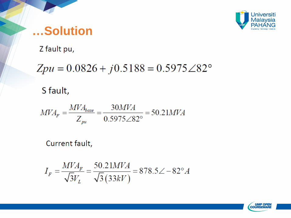
…Solution

…Solution
