chapter 6 selection of desirable route for the feasibility...
TRANSCRIPT
CHAPTER 6
SELECTION OF DESIRABLE ROUTE
FOR THE FEASIBILITY STUDY
Preparatory Survey on Eastern Corridor Development Project in the Republic of Ghana Draft Final Report
Chapter 6 Selection of Desirable Route for the Feasibility Study
6 - 1
Chapter 6 Selection of Desirable Route for the Feasibility Study
6.1 Strategies for Development of the Road Network in the Study Area
6.1.1 Future Road Network Configuration in the Study Area
(1) Present and Future Road Network in the Study Area
The trunk roads were reclassified by the MRH based on their functional importance in 1998.
The new system reclassified the roads into National, Inter-Regional and Regional Roads,
reflecting their national and socio-economic importance and tying in with the present regional
and district administrative structures of the country. Beside the trunk road network, there are
urban roads managed by the DUR, and feeder roads managed by the DFR both under the MRH.
According to the GHA, the proposed new route of the Eastern Corridor between Asutsuare
Jct. and Asikuma Jct. will be classified as a National Road after construction of the new route.
Moreover, the international traffic and major logistic corridor functions of the existing N2
between Asutsuare Jct. and Asikuma Jct. via the existing Adomi Bridge will be expected to shift
to a proposed new route with a new bridge crossing the Volta River, when the whole section of
N2 between Tema and the border with Burkina Faso will be improved.
(2) Proposed Future Road Network Configuration in the Study Area
Figure 6-1 illustrates the present road hierarchy in the Study Area. There are four national
roads (N1, N2, N3 and N5), five regional roads (R18, R23, R24 (only a short length), R28 and
R95), and various feeder roads. Considering the functional hierarchy of the road network and
regional development trend, the north-south axis and the east-axis on both the left and right
sides of the Volta River are weak.
In order to accelerate the regional development, particularly agricultural development, the
Study Team proposes the future road network configuration in the Study Area as shown in
Figure 6-2.
Under this proposed road network configuration, the new proposed route between Asutsuare
Jct. and Asikuma Jct. will be classified as a national trunk road with a function as an
international corridor between Tema and the border with Burkina Faso, while the road section
between Asutsuare and Aveyime will be a part of the inter-regional road connecting N2 and N1
via the green-belt area of Ghana, where major rice production is expected.
6.1.2 Design Standards Applied for the Study Roads and Bridges
(1) Design Speed
The design speed for the proposed roads are determined by the Road Design Guide of Ghana
and the following facts:
• The upgrading works of a part of Lot 2 of N2 between Asikuma Jct. and Have (48 km), just
after the section of proposed route (N2) in the Study, has already started with GoG fund.
The design speed for the section between Asikuma and the 37 km point from Asikuma Jct.
is 100 km/h because of flat terrain.

Preparatory Survey on Eastern Corridor Development Project in the Republic of Ghana Draft Final Report
Chapter 6 Selection of Desirable Route for the Feasibility Study
6 - 2
Source: Study Team
Figure 6-1 Present Road Hierarchy in the Study Area
Source: Study Team
Figure 6-2 Proposed Road Network Configuration in the Study Area
To consider uniformity of the design speed on the same type of terrain, design speed for the
new road section between Asutsuare Jct. and Asikuma Jct. is proposed 100 km/h based on the
Road Design Guide of Ghana.
Table 6-1 Design Speed for National Road
Road Type ClassificationDesign Speed
(km/h)
Absolute Values
(km/h)
National
Flat 100 80
Hilly 80 60
Mountainous 60 40
Source: Road Design Guide in Ghana
(2) Design Radius
In order to accommodate international logistics freight vehicles, mainly large trailers, to
secure traffic safety, and to harmonise with the natural and topographical conditions, the radius
of curves is designed to be gentle. Although the minimum design radius is 700 m for the design
speed of 100 km/h, it is desirable to use a radius of more than 2,000 m or at least 1,400 m
corresponding to two or three times the minimum design standard.
(3) Typical Cross Section
a) Lane Width
The main traffic function of the proposed road is to create a national trunk road network to
link economic and administrative centres as well as ensure efficient international logistic flows.
Preparatory Survey on Eastern Corridor Development Project in the Republic of Ghana Draft Final Report
Chapter 6 Selection of Desirable Route for the Feasibility Study
6 - 3
A lane width of 3.65 m defined in the Road Design Guide of GHA is proposed for the following
reasons:
• A lane width of 3.65 m is adopted for the section between Asikuma Jct. and Have on N2
currently being upgraded.
• A lane width of 3.65 m is also adopted for ongoing national road projects such as the N8
upgrading project.
• According to AASHTO Geometric Design of Highways and Streets (2004), the lane width
of roads classified as national highways is recommended as 3.65 m (12 feet).
Thus, a lane width of 3.65 m is proposed for the road sections between Asutsuare Jct. and
Asikuma Jct., and Asutsuare and Aveyime according to the Road Design Manual of Ghana.
b) Shoulder Width
The main function of shoulders on national roads is not only to provide space for stopping
vehicles, including broken-down vehicles, but also walking space for pedestrians. A shoulder
width of 2.50 m defined in the Road Design Guide of GHA is proposed for the following
reasons:
• A shoulder width of 2.50 m is adopted for the section between Asikuma Jct. and have on N2
currently being upgraded.
• A shoulder width of 2.00 m is adopted for the ongoing national trunk road project (N8
upgrading project). In this case, even though a consultant proposed 2.50 m to follow the
Road Design Guide of GHA, the existing shoulder width was 2.00 m following the previous
guide, and the GHA finally decided to adopt 2.00 m to comply with the existing shoulder
width.
• According to the AASHTO standard, heavily travelled, high-speed highways and highways
carrying large numbers of trucks should have usable shoulders of at least 3.0 m (10 feet).
• The Japanese standard, defines, a shoulder width of 2.50 m, and 3.25 m is preferable for
national expressways.
Thus, a shoulder width of 2.50 m is proposed for the road section between Asutsuare Jct. and
Asikuma Jct., while a shoulder width of 2.00 m is proposed for the Asutsuare and Aveyime road
which will be changed to an inter-regional road after the completion of upgrading works.
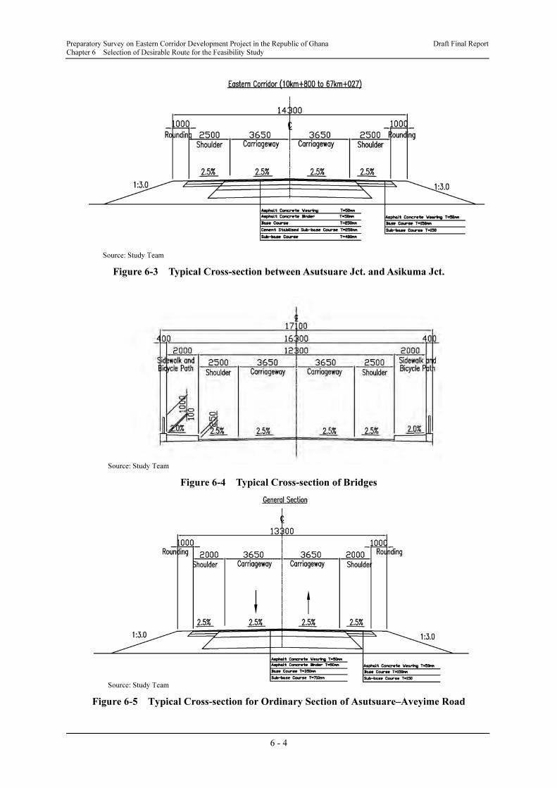
Figures 6-3 and 6-4 show typical cross-sections used for the preliminary design of ordinary
road sections and bridges, including new bridge across the Volta River, on the Eastern Corridor.
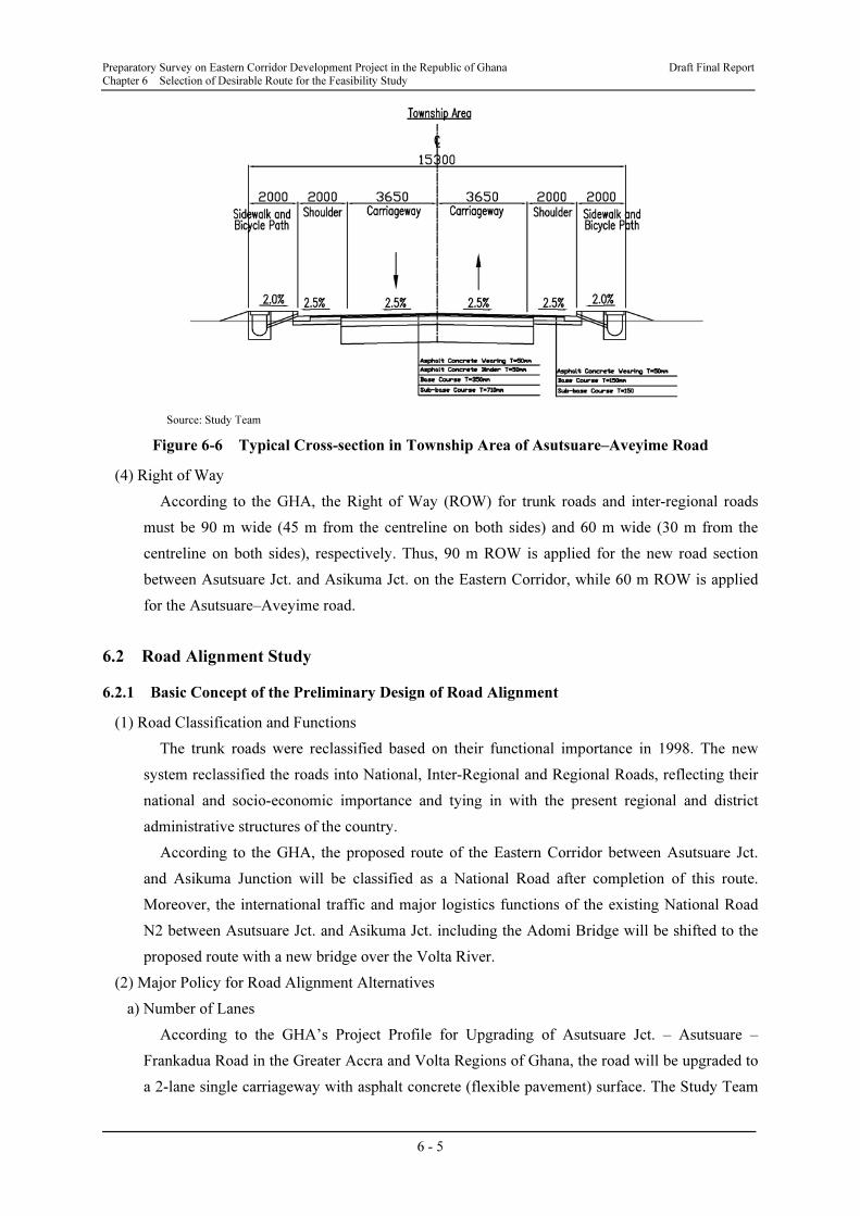
Figures 6-5 and 6-6 show typical cross-sections used for the preliminary design of ordinary road
sections and roads in townships along the Asutsuare – Aveyime road. Mount-up sidewalks on
both sides of the carriageway are proposed in order to secure the safety of both pedestrians and
bicycles for bridges and in township areas. The Study Team proposed several alternative cross
sections at the Working Group Meetings (WGM) with GHA officials, and both sides agreed to
adopt the cross-sections shown in these figures.
Preparatory Survey on Eastern Corridor Development Project in the Republic of Ghana Draft Final Report
Chapter 6 Selection of Desirable Route for the Feasibility Study
6 - 4
Source: Study Team
Figure 6-3 Typical Cross-section between Asutsuare Jct. and Asikuma Jct.
Source: Study Team
Figure 6-4 Typical Cross-section of Bridges
Source: Study Team
Figure 6-5 Typical Cross-section for Ordinary Section of Asutsuare–Aveyime Road
Preparatory Survey on Eastern Corridor Development Project in the Republic of Ghana Draft Final Report
Chapter 6 Selection of Desirable Route for the Feasibility Study
6 - 5
Source: Study Team
Figure 6-6 Typical Cross-section in Township Area of Asutsuare–Aveyime Road
(4) Right of Way
According to the GHA, the Right of Way (ROW) for trunk roads and inter-regional roads
must be 90 m wide (45 m from the centreline on both sides) and 60 m wide (30 m from the
centreline on both sides), respectively. Thus, 90 m ROW is applied for the new road section
between Asutsuare Jct. and Asikuma Jct. on the Eastern Corridor, while 60 m ROW is applied
for the Asutsuare–Aveyime road.
6.2 Road Alignment Study
6.2.1 Basic Concept of the Preliminary Design of Road Alignment
(1) Road Classification and Functions
The trunk roads were reclassified based on their functional importance in 1998. The new
system reclassified the roads into National, Inter-Regional and Regional Roads, reflecting their
national and socio-economic importance and tying in with the present regional and district
administrative structures of the country.
According to the GHA, the proposed route of the Eastern Corridor between Asutsuare Jct.
and Asikuma Junction will be classified as a National Road after completion of this route.
Moreover, the international traffic and major logistics functions of the existing National Road
N2 between Asutsuare Jct. and Asikuma Jct. including the Adomi Bridge will be shifted to the
proposed route with a new bridge over the Volta River.
(2) Major Policy for Road Alignment Alternatives
a) Number of Lanes
According to the GHA’s Project Profile for Upgrading of Asutsuare Jct. – Asutsuare –
Frankadua Road in the Greater Accra and Volta Regions of Ghana, the road will be upgraded to
a 2-lane single carriageway with asphalt concrete (flexible pavement) surface. The Study Team
Preparatory Survey on Eastern Corridor Development Project in the Republic of Ghana Draft Final Report
Chapter 6 Selection of Desirable Route for the Feasibility Study
6 - 6
has confirmed the required number of lanes for the proposed road based on the future traffic
demand forecast with the target year of 2036.
b) Considerations to Determine Road Alignment
The major considerations when determining alternative road alignments were as follows:
• To minimise the resettlement of homes and other commercial buildings
• To avoid passing through paddy fields or irrigation schemes in view of the importance of
rice cultivation, particularly on the southern side of the Volta River which is defined as the
Southern Greenbelt of Ghana with large potential for agricultural activities
• To minimise the effects on existing, on-going and planned agricultural development
schemes.
• To set the road alignment perpendicular to the Volta River and to select a location where the
river is narrow to reduce bridge construction costs.
• To minimise the number of crossings of rivers, watercourses and irrigation canals in view of
road conservation and maintenance works. Even if culverts need to be installed at
appropriate locations, water flows may change in the future due to the flat terrain in the
Study Area.
• To clearly identify locations of possible deposits of black cotton soil, where either soil
replacement or soil stabilisation works will be required.
• To consider a gentle longitudinal profile where alternative routes run alongside the
mountains near Asutsuare township. If alternative routes have a longitudinal gradient of 4%
for more than 700 m, an additional lane (climbing lane) would be considered in order to
secure the smooth flow of traffic without being affected by slow-moving heavy vehicles.
6.2.2 Road Alignment Study between Asutsuare Jct. and the Volta River
(1) Possible Alternative Routes
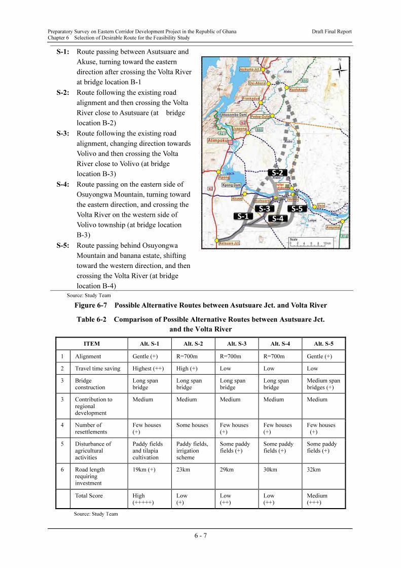
The Study Team prepared five possible alternative routes between Asutsuare Jct. and the
Volta River, as shown in Figure 6-7, in the southern part of the Study Area (S-1, S-2, S-3, S-4
and S-5), which was presented at the First Working Group Meeting (WGM) held on 18th April,
2012 for the first screening of alternative routes.
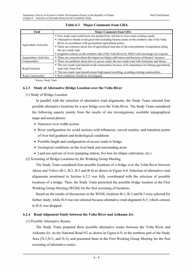
(2) Comparison of Possible Alternative Routes
Results of the initial comparison of possible alternative routes by the Study Team are
summarised in Table 6-2.
(3) Discussions in the WGM
Comments from GHA officials at the WGM are summarised in Table 6-3.
(4) Screening of Alternative Road Alignments
Based on the results of discussions in the WGM, alternative road alignments S-1, S-2, S-3
and S-4 were selected for the further study. Alternative road alignment S-5 was not selected
because it could encroach on the area where Golden Exotic Ltd. plans to expand its banana
estate.
Preparatory Survey on Eastern Corridor Development Project in the Republic of Ghana Draft Final Report
Chapter 6 Selection of Desirable Route for the Feasibility Study
6 - 7
Source: Study Team
Figure 6-7 Possible Alternative Routes between Asutsuare Jct. and Volta River
Table 6-2 Comparison of Possible Alternative Routes between Asutsuare Jct.
and the Volta River
ITEM Alt. S-1 Alt. S-2 Alt. S-3 Alt. S-4 Alt. S-5
1 Alignment Gentle (+) R=700m R=700m R=700m Gentle (+)
2 Travel time saving Highest (++) High (+) Low Low Low
3 Bridge construction
Long span bridge
Long span bridge
Long span bridge
Long span bridge
Medium span bridges (+)
3 Contribution to regional development
Medium Medium Medium Medium Medium
4 Number of resettlements
Few houses (+)
Some houses Few houses (+)
Few houses (+)
Few houses (+)
5 Disturbance of agricultural activities
Paddy fields and tilapia cultivation
Paddy fields, irrigation scheme
Some paddy fields (+)
Some paddy fields (+)
Some paddy fields (+)
6 Road length requiring investment
19km (+) 23km 29km 30km 32km
Total Score High (+++++)
Low(+)
Low(++)
Low(++)
Medium (+++)
Source: Study Team
S-1: Route passing between Asutsuare and
Akuse, turning toward the eastern
direction after crossing the Volta River
at bridge location B-1
S-2: Route following the existing road
alignment and then crossing the Volta
River close to Asutsuare (at bridge
location B-2)
S-3: Route following the existing road
alignment, changing direction towards
Volivo and then crossing the Volta
River close to Volivo (at bridge
location B-3)
S-4: Route passing on the eastern side of
Osuyongwa Mountain, turning toward
the eastern direction, and crossing the
Volta River on the western side of
Volivo township (at bridge location
B-3)
S-5: Route passing behind Osuyongwa
Mountain and banana estate, shifting
toward the western direction, and then
crossing the Volta River (at bridge
location B-4)
Preparatory Survey on Eastern Corridor Development Project in the Republic of Ghana Draft Final Report
Chapter 6 Selection of Desirable Route for the Feasibility Study
6 - 8
Table 6-3 Major Comments from GHA
Field Major Comments from GHA
Agriculture Activities
� New trunk road could boost rice productivity, but has to cross some existing canals.
� Alternatives should avoid green belt including banana estate on the southern side of the Volta
River, in accordance with government agricultural policy.
� There are concerns about loss of agricultural land due to the concentration of population along
the new trunk road.
� Irrigation scheme on the northern side of the Volta River by MiDA will encourage rice exports.
Aquaculture Activities � There are concerns about the impact on tilapia cultivation and decrease of farmers’ incomes.
Communities � There are problems about how to access safely the new trunk road with Asutsuare and Akuse.
Road Function
� The new trunk road should avoid communities because of its importance for linking agricultural
land with Tema Port.
� The new trunk road should secure high-speed travelling, avoiding existing communities.
Road Construction � Soil conditions should be investigated.
Source: Study Team
6.2.3 Study of Alternative Bridge Location over the Volta River
(1) Study of Bridge Location
In parallel with the selection of alternative road alignments, the Study Team selected four
possible alternative locations for a new bridge over the Volta River. The Study Team considered
the following aspects mainly from the results of site investigations, available topographical
maps and aerial photos:
• Narrower river width section
• River configuration (to avoid sections with tributaries, curved reaches, and transition points
of river bed gradient) and hydrological conditions
• Possible length and configuration of access roads to bridge
• Geological conditions on the river bank and surrounding areas
• Land use and use of river (pumping station, live box for tilapia cultivation, etc.)
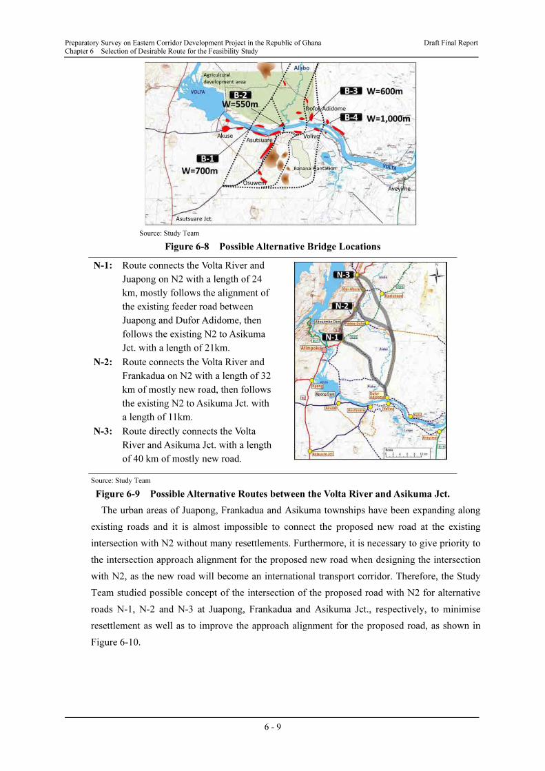
(2) Screening of Bridge Locations by the Working Group Meeting
The Study Team considered four possible locations of a bridge over the Volta River between
Akuse and Volivo (B-1, B-2, B-3 and B-4) as shown in Figure 6-8. Selection of alternative road
alignments mentioned in Section 6.2.2 was fully coordinated with the selection of possible
locations of a bridge. Then, the Study Team presented the possible bridge location at the First
Working Group Meeting (WGM) for the first screening of locations.
Based on the results of discussions in the WGM, locations B-1, B-2 and B-3 were selected for
further study, while B-4 was not selected because alternative road alignment S-5, which connect
to B-4, was dropped.
6.2.4 Road Alignment Study between the Volta River and Asikuma Jct.
(1) Possible Alternative Routes
The Study Team prepared three possible alternative routes between the Volta River and
Asikuma Jct. on the National Road N2 as shown in Figure 6-9, in the northern part of the Study
Area (N-1,N-2, and N-3), and presented them in the First Working Group Meeting for the first
screening of alternative routes.
Preparatory Survey on Eastern Corridor Development Project in the Republic of Ghana Draft Final Report
Chapter 6 Selection of Desirable Route for the Feasibility Study
6 - 9
Source: Study Team
Figure 6-8 Possible Alternative Bridge Locations
Source: Study Team
Figure 6-9 Possible Alternative Routes between the Volta River and Asikuma Jct.
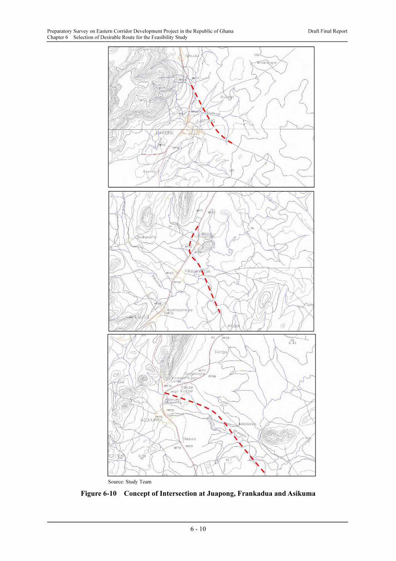
The urban areas of Juapong, Frankadua and Asikuma townships have been expanding along
existing roads and it is almost impossible to connect the proposed new road at the existing
intersection with N2 without many resettlements. Furthermore, it is necessary to give priority to
the intersection approach alignment for the proposed new road when designing the intersection
with N2, as the new road will become an international transport corridor. Therefore, the Study
Team studied possible concept of the intersection of the proposed road with N2 for alternative
roads N-1, N-2 and N-3 at Juapong, Frankadua and Asikuma Jct., respectively, to minimise
resettlement as well as to improve the approach alignment for the proposed road, as shown in
Figure 6-10.
N-1: Route connects the Volta River and
Juapong on N2 with a length of 24
km, mostly follows the alignment of
the existing feeder road between
Juapong and Dufor Adidome, then
follows the existing N2 to Asikuma
Jct. with a length of 21km.
N-2: Route connects the Volta River and
Frankadua on N2 with a length of 32
km of mostly new road, then follows
the existing N2 to Asikuma Jct. with
a length of 11km.
N-3: Route directly connects the Volta
River and Asikuma Jct. with a length
of 40 km of mostly new road.
Preparatory Survey on Eastern Corridor Development Project in the Republic of Ghana Draft Final Report
Chapter 6 Selection of Desirable Route for the Feasibility Study
6 - 10
Source: Study Team
Figure 6-10 Concept of Intersection at Juapong, Frankadua and Asikuma
Preparatory Survey on Eastern Corridor Development Project in the Republic of Ghana Draft Final Report
Chapter 6 Selection of Desirable Route for the Feasibility Study
6 - 11
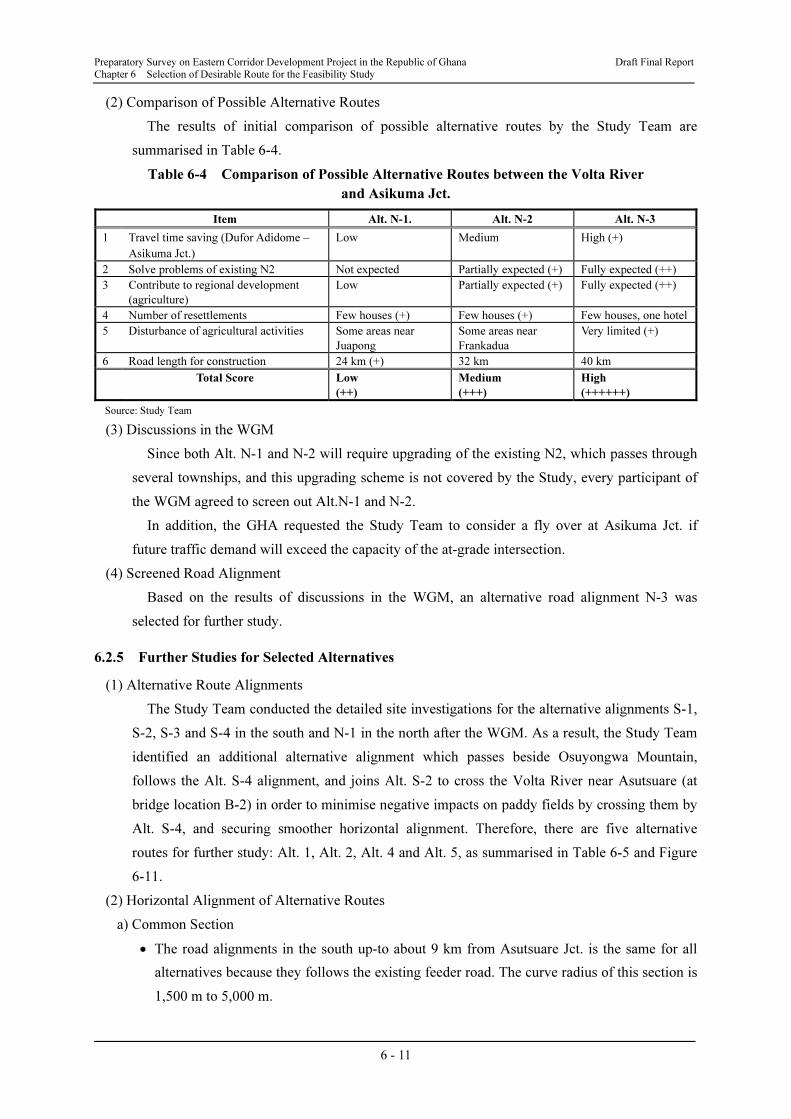
(2) Comparison of Possible Alternative Routes
The results of initial comparison of possible alternative routes by the Study Team are
summarised in Table 6-4.
Table 6-4 Comparison of Possible Alternative Routes between the Volta River
and Asikuma Jct.
Item Alt. N-1. Alt. N-2 Alt. N-3
1 Travel time saving (Dufor Adidome –
Asikuma Jct.)
Low Medium High (+)
2 Solve problems of existing N2 Not expected Partially expected (+) Fully expected (++)
3 Contribute to regional development
(agriculture)
Low Partially expected (+) Fully expected (++)
4 Number of resettlements Few houses (+) Few houses (+) Few houses, one hotel
5 Disturbance of agricultural activities Some areas near
Juapong
Some areas near
Frankadua
Very limited (+)
6 Road length for construction 24 km (+) 32 km 40 km
Total Score Low
(++)
Medium
(+++)
High
(++++++)
Source: Study Team
(3) Discussions in the WGM
Since both Alt. N-1 and N-2 will require upgrading of the existing N2, which passes through
several townships, and this upgrading scheme is not covered by the Study, every participant of
the WGM agreed to screen out Alt.N-1 and N-2.
In addition, the GHA requested the Study Team to consider a fly over at Asikuma Jct. if
future traffic demand will exceed the capacity of the at-grade intersection.
(4) Screened Road Alignment
Based on the results of discussions in the WGM, an alternative road alignment N-3 was
selected for further study.
6.2.5 Further Studies for Selected Alternatives
(1) Alternative Route Alignments
The Study Team conducted the detailed site investigations for the alternative alignments S-1,
S-2, S-3 and S-4 in the south and N-1 in the north after the WGM. As a result, the Study Team
identified an additional alternative alignment which passes beside Osuyongwa Mountain,
follows the Alt. S-4 alignment, and joins Alt. S-2 to cross the Volta River near Asutsuare (at
bridge location B-2) in order to minimise negative impacts on paddy fields by crossing them by
Alt. S-4, and securing smoother horizontal alignment. Therefore, there are five alternative
routes for further study: Alt. 1, Alt. 2, Alt. 4 and Alt. 5, as summarised in Table 6-5 and Figure
6-11.
(2) Horizontal Alignment of Alternative Routes
a) Common Section
• The road alignments in the south up-to about 9 km from Asutsuare Jct. is the same for all
alternatives because they follows the existing feeder road. The curve radius of this section is
1,500 m to 5,000 m.
Preparatory Survey on Eastern Corridor Development Project in the Republic of Ghana Draft Final Report
Chapter 6 Selection of Desirable Route for the Feasibility Study
6 - 12
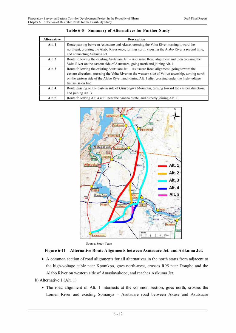
Table 6-5 Summary of Alternatives for Further Study
Alternative Description
Alt. 1 Route passing between Asutsuare and Akuse, crossing the Volta River, turning toward the
northeast, crossing the Alabo River once, turning north, crossing the Alabo River a second time,
and connecting Asikuma Jct.
Alt. 2 Route following the existing Asutsuare Jct. – Asutsuare Road alignment and then crossing the
Volta River on the eastern side of Asutsuare, going north and joining Alt. 1.
Alt. 3 Route following the existing Asutsuare Jct. – Asutsuare Road alignment, going toward the
eastern direction., crossing the Volta River on the western side of Volivo township, turning north
on the eastern side of the Alabo River, and joining Alt. 1 after crossing under the high-voltage
transmission line.
Alt. 4 Route passing on the eastern side of Osuyongwa Mountain, turning toward the eastern direction,
and joining Alt. 3.
Alt. 5 Route following Alt. 4 until near the banana estate, and directly joining Alt. 2.
Source: Study Team
Figure 6-11 Alternative Route Alignments between Asutsuare Jct. and Asikuma Jct.
• A common section of road alignments for all alternatives in the north starts from adjacent to
the high-voltage cable near Kpomkpo, goes north-west, crosses R95 near Dongbe and the
Alabo River on western side of Amasiayakope, and reaches Asikuma Jct.
b) Alternative 1 (Alt. 1)
• The road alignment of Alt. 1 intersects at the common section, goes north, crosses the
Lomen River and existing Somanya – Asutsuare road between Akuse and Asutsuare
Preparatory Survey on Eastern Corridor Development Project in the Republic of Ghana Draft Final Report
Chapter 6 Selection of Desirable Route for the Feasibility Study
6 - 13
adjacent to the Volta River, and reaches the alternative bridge location B-1 of the new Volta
River Bridge.
• After crossing the Volta River, the proposed road crosses two small rivers (Gblo River and
Nyifla River), goes north-west, crosses the existing feeder road Juapong – Adidome and the
Alabo River, and joins the common section in the north mentioned above.
c) Alternative 2 (Alt. 2)
• The road alignment of Alt. 2 mainly follows the existing feeder road Asutsuare Jct. –
Asutsuare up to 21 km point from Asutsuare Jct. near Asutsuare township, crosses the
existing feeder road Asutsuare – Aveyime, and reaches the alternative bridge location B-2
near the pumping station.
• After crossing the Volta River, the proposed road crosses the centre of the agricultural
development scheme carried out by PE-AVIV company, and join Alt. 1.
d) Alternative 3 (Alt. 3)
• The road alignment of Alt. 3 intersects from Alt. 2 near Asutsuare, runs along the existing
feeder road Asutsuare – Aveyime, and reaches the alternative bridge location B-3 near
Volivo township.
• After crossing the Volta River, the proposed road runs north on the eastern side of the Alabo
River, and joins the common section in the north.
e) Alternative 4 (Alt. 4)
• The road alignment of Alt. 4 intersects Asutsuare Jct. – Asutsuare road at the 11 km point
from Asutsuare Jct., runs east until near Asuwem township and changes direction to the
north to cross the hilly area on the east of Osuyongwa Mountain, passes the western side of
the Golden Exotics banana estate, changes direction to the east to minimise its impact on
paddy fields, and joins Alt. 3.
f) Alternative 5 (Alt. 5)
• The road alignment of Alt. 5 follows the alignment of Alt. 4 up to the eastern side of the
Golden Exotics banana estate and from the intersection with Alt. 4, goes north to join Alt. 2.
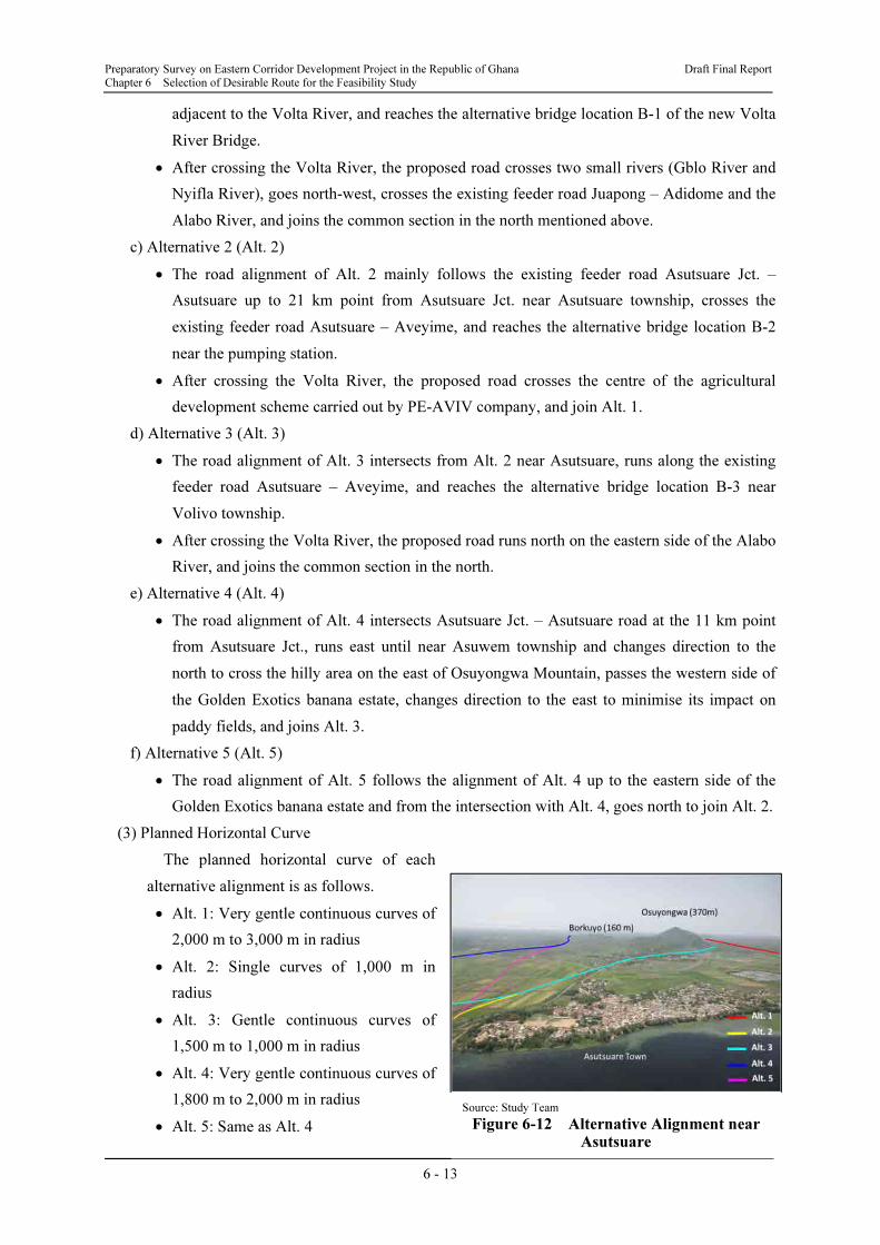
(3) Planned Horizontal Curve
The planned horizontal curve of each
alternative alignment is as follows.
• Alt. 1: Very gentle continuous curves of
2,000 m to 3,000 m in radius
• Alt. 2: Single curves of 1,000 m in
radius
• Alt. 3: Gentle continuous curves of
1,500 m to 1,000 m in radius
• Alt. 4: Very gentle continuous curves of
1,800 m to 2,000 m in radius
• Alt. 5: Same as Alt. 4
Source: Study Team
Figure 6-12 Alternative Alignment near Asutsuare
Preparatory Survey on Eastern Corridor Development Project in the Republic of Ghana Draft Final Report
Chapter 6 Selection of Desirable Route for the Feasibility Study
6 - 14
(4) Longitudinal Profile
There is basically no problem of longitudinal profile because the Study Area is mostly on flat
terrain. However, there is an exception where Alt. 4 and Alt. 5 pass on the eastern side of
Osuyongwa Mountain. The slope gradient at this section is between 2% and 3.2% (for a 500 m
section). Regarding this hilly section, however, the Study Team considers that it is not necessary
to construct an additional lane (climbing lane), because the gradient can be reduced to less than
3% by civil works.
(5) Crossing Roads
a) Section between Asutsuare Jct. and the Volta River
• Alt. 1 crosses the existing Somanya – Asutsuare road adjacent to the Volta River.
• Alt. 2, Alt. 3, Alt. 4 and Alt. 5 cross the existing feeder road Asutsuare – Aveyime,
however, this road is planned to be upgraded to an inter-regional road and an improvement
plan will be prepared in the Study.
b) Section between the Volta River and Asikuma Jct.
• Alt. 1, Alt. 2, and Alt. 5 cross the existing feeder road Juapong – Adidome on the western
side of the Alabo River.
• Alt. 3 and Alt. 4 cross the existing feeder road Juapong – Adidome on the eastern side of the
Alabo River.
• The common section of the proposed road crosses R95 between Dangbe village and
Kpalukope township,
• The common section of the proposed road is the existing feeder road Osi-Abura –
Kpakukope on the western side of Amasiayakope township.
(6) Crossing Rivers other than the Volta River
a) Section between Asutsuare Jct. and the Volta River
• Other than the Volta River and an irrigation canal of the KIS, only Alt. 1 crosses the Romen
River.
b) Section between the Volta River and Asikuma Jct.
• Alt. 1 crosses the Gblo River, Nyifla River, Honi River and Alabo River before joining the
common section of the proposed route.
• Alt. 2 and Alt. 5 cross the Honi River and Alabo River after joining Alt. 1.
• Alt. 3 and Alt. 4 do not cross a river other than small streams before joining the common
section.
• The common section crosses the Alabo River on the western side of Amasiayakope
township.
(7) Soil Condition
a) Soil Testing
From the initial site survey, the Study Team found that there is a high possibility of black
Preparatory Survey on Eastern Corridor Development Project in the Republic of Ghana Draft Final Report
Chapter 6 Selection of Desirable Route for the Feasibility Study
6 - 15
cotton soil21
deposit based on the FAO Soil Classification Map of the Study Area shown in
Figure 2-15.
In order to identify possible areas of black cotton soil deposit along the proposed alternative
road alignments, the Study Team conducted a soil investigation focusing on black cotton soil
deposits in May 2012, with cooperation from the Material Division of the GHA by collecting
samples and laboratory tests.
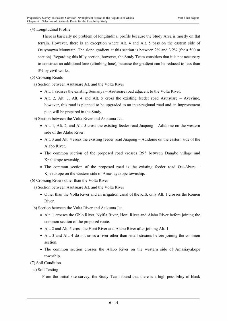
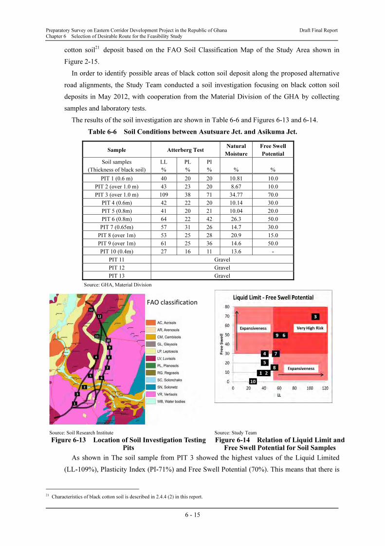
The results of the soil investigation are shown in Table 6-6 and Figures 6-13 and 6-14.
Table 6-6 Soil Conditions between Asutsuare Jct. and Asikuma Jct.
Sample Atterberg Test Natural
Moisture
Free Swell
Potential
Soil samples LL PL PI
(Thickness of black soil) % % % % %
PIT 1 (0.6 m) 40 20 20 10.81 10.0
PIT 2 (over 1.0 m) 43 23 20 8.67 10.0
PIT 3 (over 1.0 m) 109 38 71 34.77 70.0
PIT 4 (0.6m) 42 22 20 10.14 30.0
PIT 5 (0.8m) 41 20 21 10.04 20.0
PIT 6 (0.8m) 64 22 42 26.3 50.0
PIT 7 (0.65m) 57 31 26 14.7 30.0
PIT 8 (over 1m) 53 25 28 20.9 15.0
PIT 9 (over 1m) 61 25 36 14.6 50.0
PIT 10 (0.4m) 27 16 11 13.6 -
PIT 11 Gravel
PIT 12 Gravel
PIT 13 Gravel
Source: GHA, Material Division
Source: Soil Research Institute
Figure 6-13 Location of Soil Investigation Testing Pits
Source: Study Team
Figure 6-14 Relation of Liquid Limit and Free Swell Potential for Soil Samples
As shown in The soil sample from PIT 3 showed the highest values of the Liquid Limited
(LL-109%), Plasticity Index (PI-71%) and Free Swell Potential (70%). This means that there is
21 Characteristics of black cotton soil is described in 2.4.4 (2) in this report.
FAO classification
Preparatory Survey on Eastern Corridor Development Project in the Republic of Ghana Draft Final Report
Chapter 6 Selection of Desirable Route for the Feasibility Study
6 - 16
the highest risk of extensive black cotton soil in the area around PIT 3. Other than PIT 3, LL
values exceeding 50% were found for samples from PITs 6, 7, 8 and 9, while Free Swell
Potential values of more than 30% were found for samples from PITs 6, 7 and 9. These results
also means a higher risk of extensive black cotton soils in these areas as well.
b) Countermeasures
There are several countermeasures for the black cotton layer, such as replacing the black
cotton layer or using lime-stone stabilisation, in order to stabilise the subgrade and prevent
shrinking and swelling of black cotton soil, etc. This Study proposes replacement of the black
cotton layer because the lime stone stabilisation method would be more expensive in Ghana.
6.2.6 Bridge and Drainage Structure Study
This section describes bridge and drainage structural study other than for the Volta River.
(1) Structure Type to Cross Rivers and Irrigation Canal
Construction of a bridge is proposed for a location where the alternative route cross the
following rivers. While the Study Team proposes that drainage structures over small streams
(less than 30 m of width) and an irrigation canal are planned to be concrete culverts (either box
culver or pipe culvert).
• Alt. 1: Lomen River (100 m), Gblo River (30 m), Alabo River (55 m)
• Alt. 2: Lomen River (50 m), Alabo River (55 m)
• Alt. 3: Lomen River (50 m)
• Alt. 5: Alabo River (55 m)
• Common section in the north: Alabo River (50m)
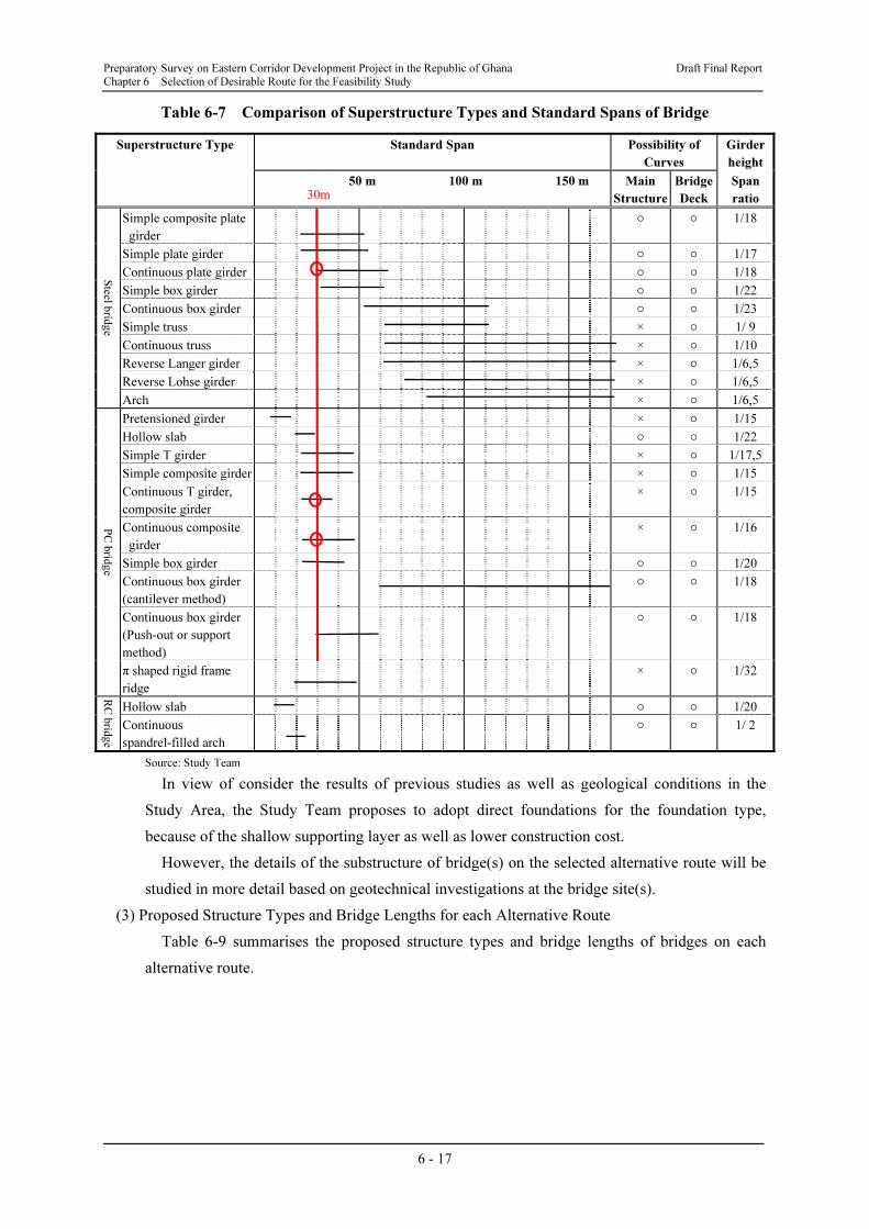
(2) Bridge Type
a) Selection of Superstructure Type
With reference to Table 6-7, a continuous T-girder bridge is selected for the following
reasons:
• Continuous structures, which are more resistant to earthquakes, are mainly compared.
• Concrete bridges are maintenance-free and economical.
• These types of bridges are commonly used in Ghana.
• As PC continuous composite girder bridge is unfavourable in terms of ease of construction
and quality control compared with a PC continuous T-girder bridge, and offers no
advantage.
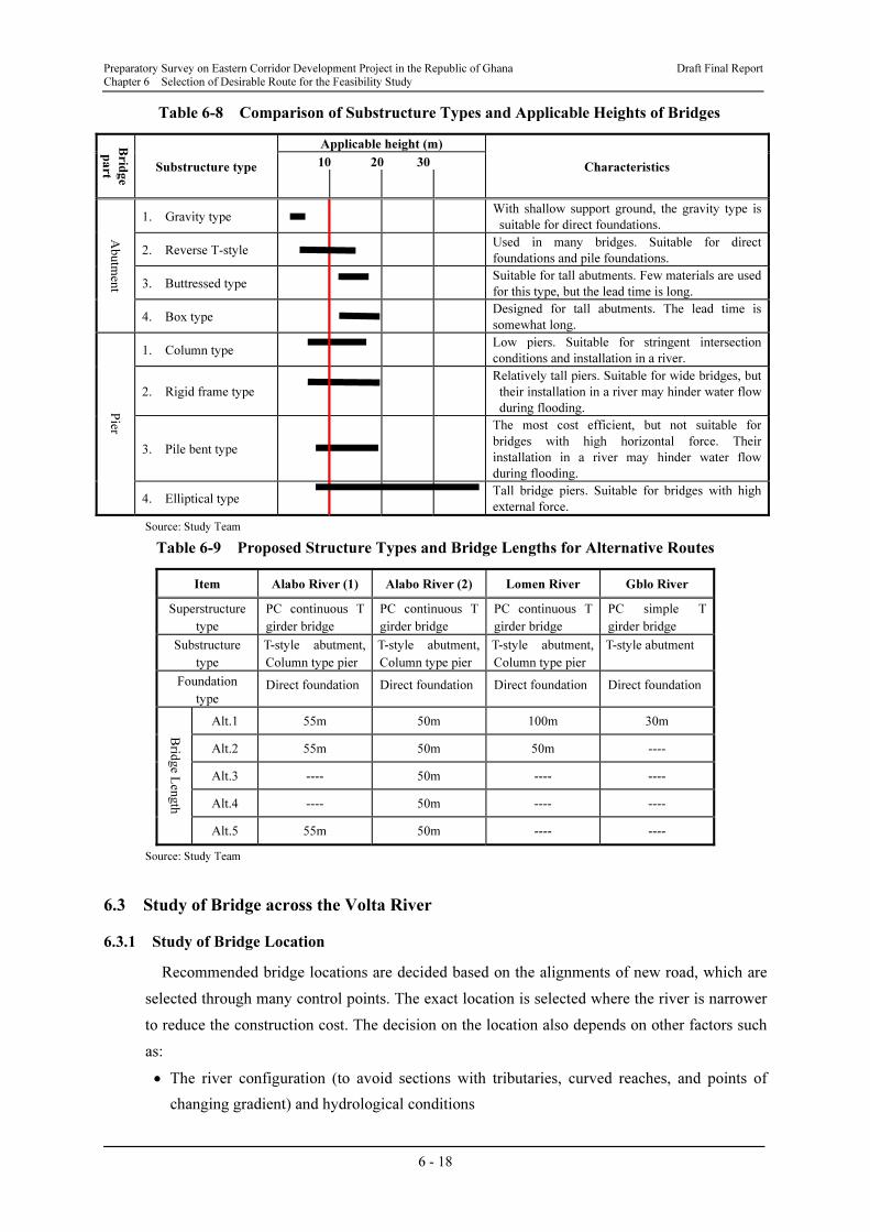
b) Selection of Substructure Type
Table 6-8 compares the applicable bridge substructure type and standard bridge height. Since
a substructure height of about 10 m is required for every bridge according to site investigations,
the Study Team proposes the reverse T-style abutment for all bridges. In the case of bridge piers,
the Study Team proposes column piers for every bridge in order to minimise negative impacts
on the river flow and better workability.
Preparatory Survey on Eastern Corridor Development Project in the Republic of Ghana Draft Final Report
Chapter 6 Selection of Desirable Route for the Feasibility Study
6 - 17
Table 6-7 Comparison of Superstructure Types and Standard Spans of Bridge
Superstructure Type Standard Span Possibility of
Curves
Girder
height
50 m 100 m 150 m Main
Structure
Bridge
Deck
Span
ratio
Steel b
ridg
e
Simple composite plate
girder
○ ○ 1/18
Simple plate girder ○ ○ 1/17
Continuous plate girder ○ ○ 1/18
Simple box girder ○ ○ 1/22
Continuous box girder ○ ○ 1/23
Simple truss × ○ 1/ 9
Continuous truss × ○ 1/10
Reverse Langer girder × ○ 1/6,5
Reverse Lohse girder × ○ 1/6,5
Arch × ○ 1/6,5
PC
brid
ge
Pretensioned girder × ○ 1/15
Hollow slab ○ ○ 1/22
Simple T girder × ○ 1/17,5
Simple composite girder × ○ 1/15
Continuous T girder,
composite girder
× ○ 1/15
Continuous composite
girder
× ○ 1/16
Simple box girder ○ ○ 1/20
Continuous box girder
(cantilever method)
○ ○ 1/18
Continuous box girder
(Push-out or support
method)
○ ○ 1/18
π shaped rigid frame
ridge
× ○ 1/32
RC
brid
ge
Hollow slab ○ ○ 1/20
Continuous
spandrel-filled arch
○ ○ 1/ 2
Source: Study Team
In view of consider the results of previous studies as well as geological conditions in the
Study Area, the Study Team proposes to adopt direct foundations for the foundation type,
because of the shallow supporting layer as well as lower construction cost.
However, the details of the substructure of bridge(s) on the selected alternative route will be
studied in more detail based on geotechnical investigations at the bridge site(s).
(3) Proposed Structure Types and Bridge Lengths for each Alternative Route
Table 6-9 summarises the proposed structure types and bridge lengths of bridges on each
alternative route.
30m
Preparatory Survey on Eastern Corridor Development Project in the Republic of Ghana Draft Final Report
Chapter 6 Selection of Desirable Route for the Feasibility Study
6 - 18
Table 6-8 Comparison of Substructure Types and Applicable Heights of Bridges
Brid
ge
part
Substructure type
Applicable height (m)
Characteristics 10 20 30
Abutm
ent
1. Gravity type With shallow support ground, the gravity type is
suitable for direct foundations.
2. Reverse T-style Used in many bridges. Suitable for direct
foundations and pile foundations.
3. Buttressed type Suitable for tall abutments. Few materials are used
for this type, but the lead time is long.
4. Box type Designed for tall abutments. The lead time is
somewhat long.
Pier
1. Column type Low piers. Suitable for stringent intersection
conditions and installation in a river.
2. Rigid frame type
Relatively tall piers. Suitable for wide bridges, but
their installation in a river may hinder water flow
during flooding.
3. Pile bent type
The most cost efficient, but not suitable for
bridges with high horizontal force. Their
installation in a river may hinder water flow
during flooding.
4. Elliptical type Tall bridge piers. Suitable for bridges with high
external force.
Source: Study Team
Table 6-9 Proposed Structure Types and Bridge Lengths for Alternative Routes
Item Alabo River (1) Alabo River (2) Lomen River Gblo River
Superstructure
type
PC continuous T
girder bridge
PC continuous T
girder bridge
PC continuous T
girder bridge
PC simple T
girder bridge
Substructure
type
T-style abutment,
Column type pier
T-style abutment,
Column type pier
T-style abutment,
Column type pier
T-style abutment
Foundation
type Direct foundation Direct foundation Direct foundation Direct foundation
Brid
ge L
ength
Alt.1 55m 50m 100m 30m
Alt.2 55m 50m 50m ----
Alt.3 ---- 50m ---- ----
Alt.4 ---- 50m ---- ----
Alt.5 55m 50m ---- ----
Source: Study Team
6.3 Study of Bridge across the Volta River
6.3.1 Study of Bridge Location
Recommended bridge locations are decided based on the alignments of new road, which are
selected through many control points. The exact location is selected where the river is narrower
to reduce the construction cost. The decision on the location also depends on other factors such
as:
• The river configuration (to avoid sections with tributaries, curved reaches, and points of
changing gradient) and hydrological conditions
Preparatory Survey on Eastern Corridor Development Project in the Republic of Ghana Draft Final Report
Chapter 6 Selection of Desirable Route for the Feasibility Study
6 - 19
• Length and configuration of access road
• Geological conditions at the river and surrounding areas
• The state of usage of the river and surrounding areas (to consider temporary uses for
construction)
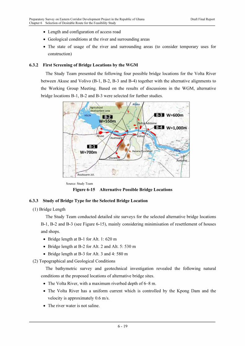
6.3.2 First Screening of Bridge Locations by the WGM
The Study Team presented the following four possible bridge locations for the Volta River
between Akuse and Volivo (B-1, B-2, B-3 and B-4) together with the alternative alignments to
the Working Group Meeting. Based on the results of discussions in the WGM, alternative
bridge locations B-1, B-2 and B-3 were selected for further studies.
Source: Study Team
Figure 6-15 Alternative Possible Bridge Locations
6.3.3 Study of Bridge Type for the Selected Bridge Location
(1) Bridge Length
The Study Team conducted detailed site surveys for the selected alternative bridge locations
B-1, B-2 and B-3 (see Figure 6-15), mainly considering minimisation of resettlement of houses
and shops.
• Bridge length at B-1 for Alt. 1: 620 m
• Bridge length at B-2 for Alt. 2 and Alt. 5: 530 m
• Bridge length at B-3 for Alt. 3 and 4: 580 m
(2) Topographical and Geological Conditions
The bathymetric survey and geotechnical investigation revealed the following natural
conditions at the proposed locations of alternative bridge sites.
• The Volta River, with a maximum riverbed depth of 6–8 m.
• The Volta River has a uniform current which is controlled by the Kpong Dam and the
velocity is approximately 0.6 m/s.
• The river water is not saline.

Preparatory Survey on Eastern Corridor Development Project in the Republic of Ghana Draft Final Report
Chapter 6 Selection of Desirable Route for the Feasibility Study
6 - 20
Source: Study Team
Figure 6-16 Locations of Selected Alternative Bridges
• The support layer is very near to the river bed, with a minimum depth of 3–6 m from the
river bed.
• The support layer is a very hard rock layer with an N-value of more than 300.
(3) Seismic Load
a) Seismic Resistance Design Standard
The Study Team used the Japanese standard when considering the seismic design of the new
bridge for the Volta River because Japan has experienced several big earthquakes and structures
have been upgraded to withstand the seismic forces. The Japanese standard considers two types
earthquakes. One is the probable earthquake during the service life of the structure and is called
the “Level I” earthquake. The other is a rare but very big earthquake called the “level II”
earthquake. Each earthquake level requires performance (see Table 6-10). Therefore, the
Japanese standard is designed to give bridges seismic resistance against either weak or strong
earthquakes.
Table 6-10 Design Seismic Resistance and Required Performance
Earthquake Type Required Performance
Level I earthquake After an earthquake, bridge structures will not be broken.
Level II earthquake After an earthquake, damage will be limited to allow a part and functions of
the bridge to be quickly restored.
Source: Study Team
b) Level I Earthquake
The maximum response acceleration is estimated by considering past earthquakes in and
around the Study Area, formula for distance damping and difference between response
acceleration and ground level acceleration. The design return period is 75 years as the probable
earthquake during the service life of structures. The size of earthquake in this period is
estimated by using the revised epicentre distance (see Table 6-11).
Alt.1 Alt.3 Alt.2
Alt.4 Alt.5
B-1 B-2
B-3
Preparatory Survey on Eastern Corridor Development Project in the Republic of Ghana Draft Final Report
Chapter 6 Selection of Desirable Route for the Feasibility Study
6 - 21
Table 6-11 Past Earthquakes and Level I Maximum Response Acceleration
Year Magnitude
Epicentre
Distance
(km)
Historic Return Period
(year)
Revise
Epicentre
Distance (km)
Ground Level
Acceleration
(gal)
Max Response
Acceleration
(gal)
1636 5.7 290.0 ---- ---- ---- ---- ----
1862 6.5 99.4 (2012-1862)/2= 75 121.7 55.2 108
1872 4.9 98.9 (2012-1862)/4= 37.5 85.6 34.7 68
1906 5.0 101.0 (2012-1862)/4= 37.5 87.5 35.8 70
1939 6.4 114.0 (2012-1862)/2= 75 139.6 45.9 90
Design maximum response acceleration = 110 gal
Source: Study Team
• Revise epicentre distance = epicentre distance × (historical return period)0.5
/ (design return
period)0.5
• Ground level acceleration = 987.4×100.216
M×(Δ+30)-1.218
M: Magnitude Δ: Epicentre distance
• Max response acceleration = (ratio between response acceleration and ground level
acceleration in Japanese standard = 200/102.24) × ground level acceleration
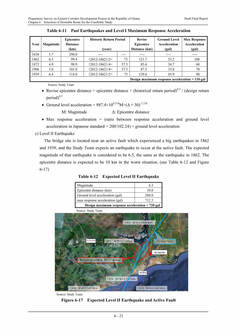
c) Level II Earthquake
The bridge site is located near an active fault which experienced a big earthquakes in 1862
and 1939, and the Study Team expects an earthquake to occur at the active fault. The expected
magnitude of that earthquake is considered to be 6.5, the same as the earthquake in 1862. The
epicentre distance is expected to be 10 km in the worst situation. (see Table 6-12 and Figure
6-17)
Table 6-12 Expected Level II Earthquake
Magnitude 6.5
Epicentre distance (km) 10.0
Ground level acceleration (gal) 280.0
max response acceleration (gal) 712.5
Design maximum response acceleration = 720 gal
Source: Study Team
Source: Study Team
Figure 6-17 Expected Level II Earthquake and Active Fault

Preparatory Survey on Eastern Corridor Development Project in the Republic of Ghana Draft Final Report
Chapter 6 Selection of Desirable Route for the Feasibility Study
6 - 22
• Ground level acceleration = 987.4×100.216
M×(Δ+30)-1.218
M: Magnitude Δ: Epicentre distance
• Max response acceleration = (ratio between response acceleration and ground level
acceleration in Japanese standard = 2000/786) × ground level acceleration
6.3.4 Preliminary Study of the Bridge across the Volta River
(1) First-Step Comparison of Superstructures
a) Selection of Alternatives Superstructure Types for the First-Step Comparison
With reference to Table 6-13, possible combinations of bridge types and span allocations for
this bridge, were selected and seven alternatives steel bridges and six alternative PC bridges
were chosen for the comparison, mainly considering the following points:
• A simple girder type was not selected for the comparison, because this type of bridge could
fall off a pier and has less seismic resistance.
• Steel Langar girder, steel Lohse girder and steel arch types were not selected because they
are suitable for only short-span bridges.
• The pretensioned girder type was not selected because there is no girder manufacturing
workshop in Ghana.
• A PC π shaped rigid frame bridge was not selected, because this type is basically used for
flyover bridges and there is no example of its use for a river bridge.
• PC Hollow slab, RC Hollow slab and RC continuous spandrel-filled arch types were not
selected because their applicable span length was too short for this bridge.
• The steel continuous box girder type was not selected because the production and
transportation of the steel girder are expensive, advanced technology and equipment are
required for erection of girders, and there is no merit compared with the truss girder type for
the same bridge span.
• The PC continuous composite girder type was not selected, because it is unfavourable in
terms of ease of construction and quality control compared with the PC T-girder type.
• The PC continuous box girder (push-out or support method) is less economical for a 40 m
span length compared with the PC T-girder type and almost the same economical level for a
60 m span length compared with the PC T-girder type using the cantilever method. This
type, however, would become one of the longest girder lengths if applied in this bridge.
Thus, this type was not selected because of difficulty of construction, because advanced
technology would be required for construction with the push-out method.
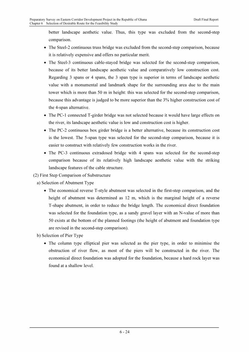
• b) Selection of Alternatives Superstructure Types for the Second Step Comparison
• For the 13 alternative superstructure types for the first-step comparison, a second-step
comparison was made, considering the effects on the river flow, landscape aesthetic value,
ease of maintenance and construction cost, as shown in Table 6-14. Based on this
comparison, the following three alternative superstructure types were selected for the
following reasons:

Preparatory Survey on Eastern Corridor Development Project in the Republic of Ghana Draft Final Report
Chapter 6 Selection of Desirable Route for the Feasibility Study
6 - 23
Table 6-13 Comparison of Superstructure Types and Standard Spans of Bridge
Superstructure Type Standard Span Evaluation Judgment
50 m 100 m 150 m
Steel b
ridg
e
Simple composite plate
girder
Not applicable No
Simple plate girder Less seismic
resistance
No
Continuous plate girder Applicable Yes
Simple box girder Less seismic
resistance
No
Continuous box girder Less
economical
than truss
No
Simple truss Less seismic
resistance
Yes
Continuous truss Applicable Yes
Reverse Langer girder Not applicable No
Reverse Lohse girder Not applicable No
Arch Not applicable No
Continuous cable-stayed
bridge
Applicable Yes
PC
brid
ge
Pretensioned girder Not applicable No
Hollow slab Applicable span
is too short
No
Simple T girder Less seismic
resistance
No
Simple composite girder Less seismic
resistance
No
Continuous T girder, Applicable Yes
Continuous composite
girder
Less
economical
than T-girder
No
Simple box girder Less seismic
resistance
No
Continuous box girder
(cantilever method)
Applicable Yes
Continuous box girder
(Push-out or support
method)
Less
economical
than T-girder
No
π shaped rigid frame
bridge
Not applicable No
Continuous extradosed
bridge
Applicable Yes
RC
brid
ge
Hollow slab Applicable span
is too short
No
Continuous
spandrel-filled arch
Applicable span
is too short
No
Source: Study Team
Alternative 1: Steel-3 – Continuous cable-stayed bridge (Span: 117.5 + 265.0 + 117.5)
Alternative 2: PC-2 – Continuous box girder bridge (Span: 70 + 3@120 ; 70)
Alternative 3: PC-3 – Continuous extradosed bridge (Span: 95 + 2@155 + 95)
• Even though the Steel-1 Continuous plate girder type is relatively cheaper with a span of 60
m, it is difficult to construct due to many construction works in the river and it offers no
Preparatory Survey on Eastern Corridor Development Project in the Republic of Ghana Draft Final Report
Chapter 6 Selection of Desirable Route for the Feasibility Study
6 - 24
better landscape aesthetic value. Thus, this type was excluded from the second-step
comparison.
• The Steel-2 continuous truss bridge was excluded from the second-step comparison, because
it is relatively expensive and offers no particular merit.
• The Steel-3 continuous cable-stayed bridge was selected for the second-step comparison,
because of its better landscape aesthetic value and comparatively low construction cost.
Regarding 3 spans or 4 spans, the 3 span type is superior in terms of landscape aesthetic
value with a monumental and landmark shape for the surrounding area due to the main
tower which is more than 50 m in height: this was selected for the second-step comparison,
because this advantage is judged to be more superior than the 3% higher construction cost of
the 4-span alternative.
• The PC-1 connected T-girder bridge was not selected because it would have large effects on
the river, its landscape aesthetic value is low and construction cost is higher.
• The PC-2 continuous box girder bridge is a better alternative, because its construction cost
is the lowest. The 5-span type was selected for the second-step comparison, because it is
easier to construct with relatively few construction works in the river.
• The PC-3 continuous extradosed bridge with 4 spans was selected for the second-step
comparison because of its relatively high landscape aesthetic value with the striking
landscape features of the cable structure.
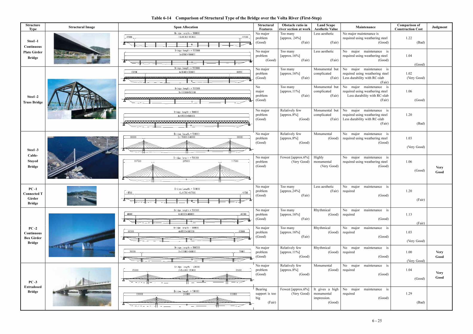
(2) First Step Comparison of Substructure
a) Selection of Abutment Type
• The economical reverse T-style abutment was selected in the first-step comparison, and the
height of abutment was determined as 12 m, which is the marginal height of a reverse
T-shape abutment, in order to reduce the bridge length. The economical direct foundation
was selected for the foundation type, as a sandy gravel layer with an N-value of more than
50 exists at the bottom of the planned footings (the height of abutment and foundation type
are revised in the second-step comparison).
b) Selection of Pier Type
• The column type elliptical pier was selected as the pier type, in order to minimise the
obstruction of river flow, as most of the piers will be constructed in the river. The
economical direct foundation was adopted for the foundation, because a hard rock layer was
found at a shallow level.
6 - 25
Table 6-14 Comparison of Structural Type of the Bridge over the Volta River (First-Step)
Structure Type
Structural Image Span Allocation Structural Features
Obstacle ratio in river section at work
Land Scape Aesthetic Value
Maintenance Comparison of
Construction CostJudgment
Steel -1
Continuous
Plate Girder
Bridge
No major
problem
(Good)
Too many
[approx. 24%]
(Fair)
Less aesthetic
(Fair)
No major maintenance is
required using weathering steel
(Good)
1.22
(Bad)
No major
problem
(Good)
Too many
[approx.16%]
(Fair)
Less aesthetic
(Fair)
No major maintenance is
required using weathering steel
(Good)
1.04
(Good)
Steel -2
Truss Bridge
No major
problem
(Good)
Too many
[approx.16%]
(Fair)
Monumental but
complicated
(Fair)
No major maintenance is
required using weathering steel
Less durability with RC-slab
(Fair)
1.02
(Very Good)
No
major
problem
(Good)
Too many
[approx.11%]
(Fair)
Monumental but
complicated
(Fair)
No major maintenance is
required using weathering steel
Less durability with RC-slab
(Fair)
1.06
(Good)
No major
problem
(Good)
Relatively few
[approx.8%]
(Good)
Monumental but
complicated
(Fair)
No major maintenance is
required using weathering steel
Less durability with RC-slab
(Fair)
1.20
(Bad)
Steel -3
Cable-
Stayed
Bridge
No major
problem
(Good)
Relatively few
[approx.8%]
(Good)
Monumental
(Good)
No major maintenance is
required using weathering steel
(Good)
1.03
(Very Good)
No major
problem
(Good)
Fewest [approx.6%]
(Very Good)
Highly
monumental
(Very Good)
No major maintenance is
required using weathering steel
(Good)
1.06
(Good)Very
Good
PC -1
Connected T
Girder
Bridge
No major
problem
(Good)
Too many
[approx.24%]
(Fair)
Less aesthetic
(Fair)
No major maintenance is
required
(Good)
1.20
(Fair)
PC -2
Continuous
Box Girder
Bridge
No major
problem
(Good)
Too many
[approx.16%]
(Fair)
Rhythmical
(Good)
No major maintenance is
required
(Good)
1.13
(Fair)
No major
problem
(Good)
Too many
[approx.16%]
(Fair)
Rhythmical
(Good)
No major maintenance is
required
(Good)
1.03
(Very Good)
No major
problem
(Good)
Relatively few
[approx.11%]
(Good)
Rhythmical
(Good)
No major maintenance is
required
(Good)
1.00
(Very Good)
Very
Good
PC -3
Extradosed
Bridge
No major
problem
(Good)
Relatively few
[approx.8%]
(Good)
Monumental
(Good)
No major maintenance is
required
(Good)
1.04
(Good)
Very
Good
Bearing
support is too
big
(Fair)
Fewest [approx.6%]
(Very Good)
It gives a high
monumental
impression.
(Good)
No major maintenance is
required
(Good)
1.29
(Bad)
Preparatory Survey on Eastern Corridor Development Project in the Republic of Ghana Draft Final Report Chapter 6 Selection of Desirable Route for the Feasibility Study
6 - 26
Table 6-15 Comparison of Substructure Types and Applicable Heights of Bridges
Brid
ge
part Substructure type
Applicable height (m)
Characteristics 10 20 30
Abutm
ent
1. Gravity type With shallow support ground, the gravity type is
suitable for direct foundations.
2. Reverse T-style Used in many bridges. Suitable for direct
foundations and pile foundations.
3. Buttressed type Suitable for tall abutments. Few materials are used
for this type, but the lead time is long.
4. Box type Designed for tall abutments. The lead time is
somewhat long.
Pier
1. Column type Low piers. Suitable for stringent intersection
conditions and installation in a river.
2. Rigid frame type
Relatively tall piers. Suitable for wide bridges, but
their installation in a river may hinder water flow
during flooding.
3. Pile bent type
The most cost efficient, but not suitable for
bridges with high horizontal force. Their
installation in a river may hinder water flow
during flooding.
4. Elliptical type Tall bridge piers. Suitable for bridges with high
external force.
Source: Study Team
6.4 Road Alignment Study between Asutsuare and Aveyime
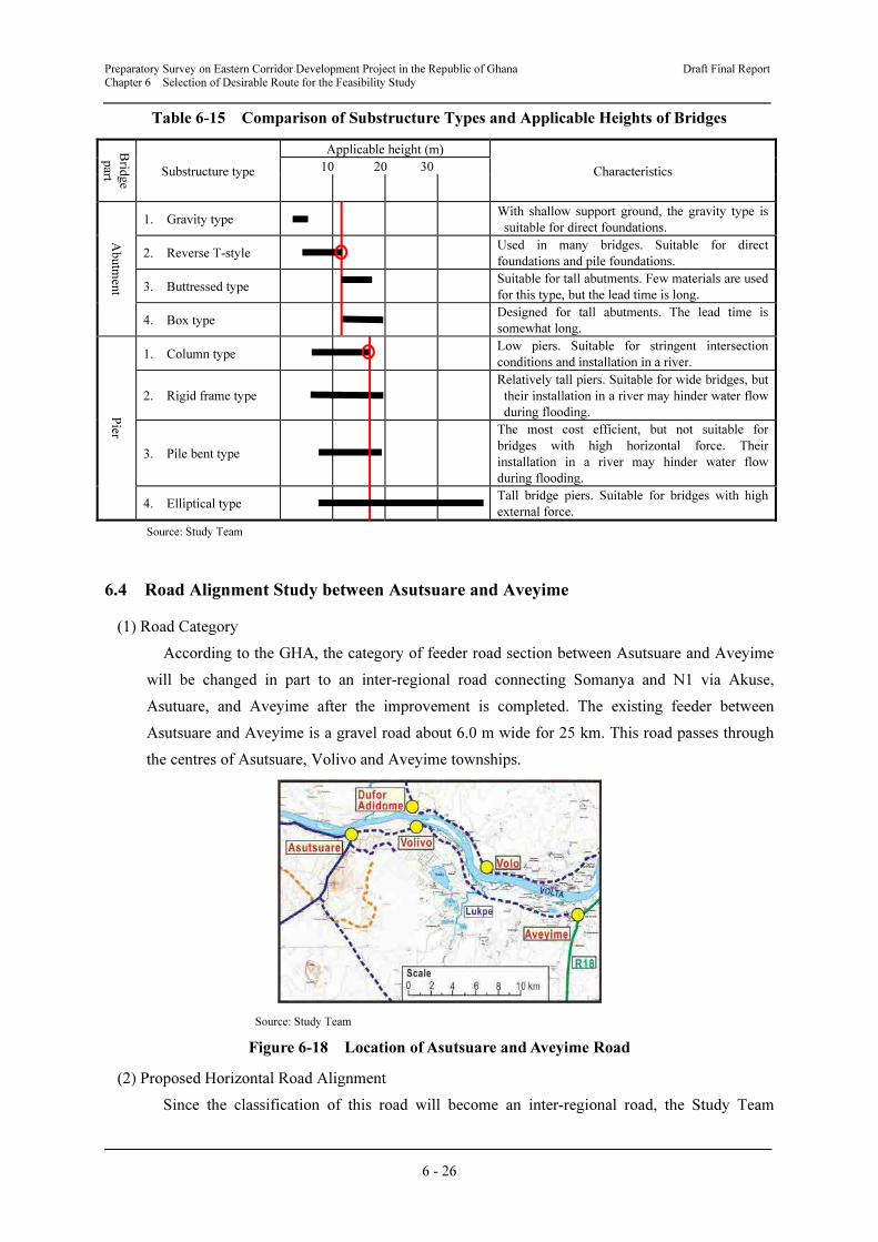
(1) Road Category
According to the GHA, the category of feeder road section between Asutsuare and Aveyime
will be changed in part to an inter-regional road connecting Somanya and N1 via Akuse,
Asutuare, and Aveyime after the improvement is completed. The existing feeder between
Asutsuare and Aveyime is a gravel road about 6.0 m wide for 25 km. This road passes through
the centres of Asutsuare, Volivo and Aveyime townships.
Source: Study Team
Figure 6-18 Location of Asutsuare and Aveyime Road
(2) Proposed Horizontal Road Alignment
Since the classification of this road will become an inter-regional road, the Study Team
Preparatory Survey on Eastern Corridor Development Project in the Republic of Ghana Draft Final Report Chapter 6 Selection of Desirable Route for the Feasibility Study
6 - 27
proposes that the horizontal alignment of this road section should basically follow the existing
road alignment, except at sections on the east of Asutsuare township, where the existing road
crosses two irrigation canals: in Volivo township, where the present alignment will not satisfy
the minimum curve radius: and in Aveyime township, where some houses are encroaching on
the road and there is a T-shape intersection adjacent to the Aveyime roundabout.
The preliminary design of this road section will be carried out in the next stage of the Study,
when topographical maps will be created based on topographical surveys.
(3) Proposed Longitudinal Profile
Since the topography along this road is totally flat on the Accra Plain along the Volta River,
there are no problems of longitudinal profile for the proposed improvement.
(4) Crossing Road
There is no classified cross road other than minor gravel feeder roads.
(5) Crossing Rivers and Streams
There is only one river, the Lupe River, which is located around 15 km from Asutsuare and
there is one double box-culvert at present. Since the Norboyita Dam is planned on the upper
reaches of the Lupe River, the water discharge volume and current velocity are expected to be
controlled by this dam.
6.5 Rough Cost Estimation
6.5.1 Study of Unit Construction Cost
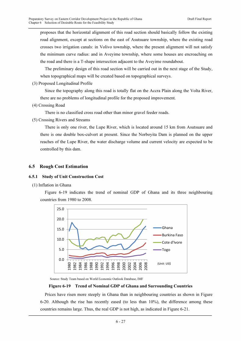
(1) Inflation in Ghana
Figure 6-19 indicates the trend of nominal GDP of Ghana and its three neighbouring
countries from 1980 to 2008.
Source: Study Team based on World Economic Outlook Database, IMF
Figure 6-19 Trend of Nominal GDP of Ghana and Surrounding Countries
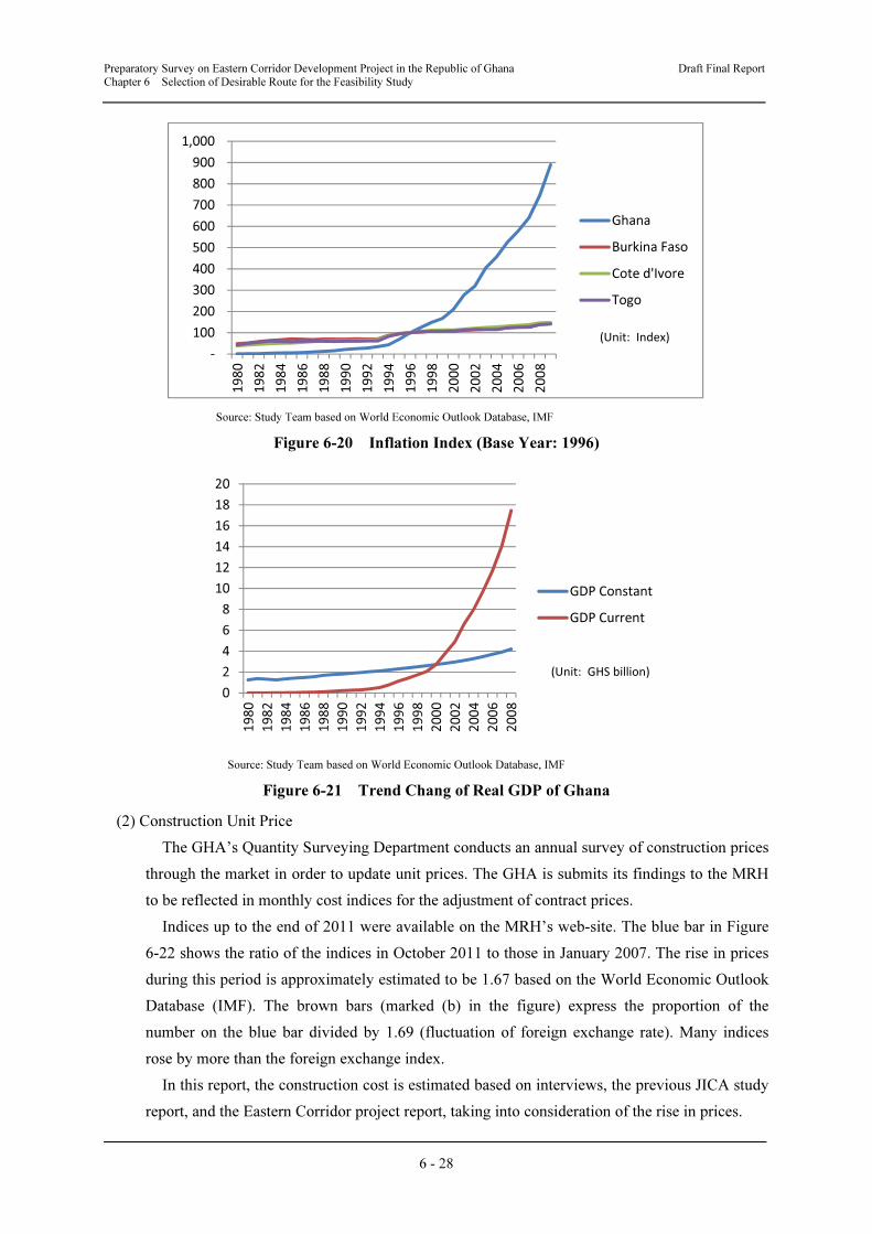
Prices have risen more steeply in Ghana than in neighbouring countries as shown in Figure
6-20. Although the rise has recently eased (to less than 10%), the difference among these
countries remains large. Thus, the real GDP is not high, as indicated in Figure 6-21.
0.0
5.0
10.0
15.0
20.0
25.0
1980
1982
1984
1986
1988
1990
1992
1994
1996
1998
2000
2002
2004
2006
2008
Ghana
Burkina Faso
Cote d'Ivore
Togo
(Unit: US$
Preparatory Survey on Eastern Corridor Development Project in the Republic of Ghana Draft Final Report Chapter 6 Selection of Desirable Route for the Feasibility Study
6 - 28
Source: Study Team based on World Economic Outlook Database, IMF
Figure 6-20 Inflation Index (Base Year: 1996)
Source: Study Team based on World Economic Outlook Database, IMF
Figure 6-21 Trend Chang of Real GDP of Ghana
(2) Construction Unit Price
The GHA’s Quantity Surveying Department conducts an annual survey of construction prices
through the market in order to update unit prices. The GHA is submits its findings to the MRH
to be reflected in monthly cost indices for the adjustment of contract prices.
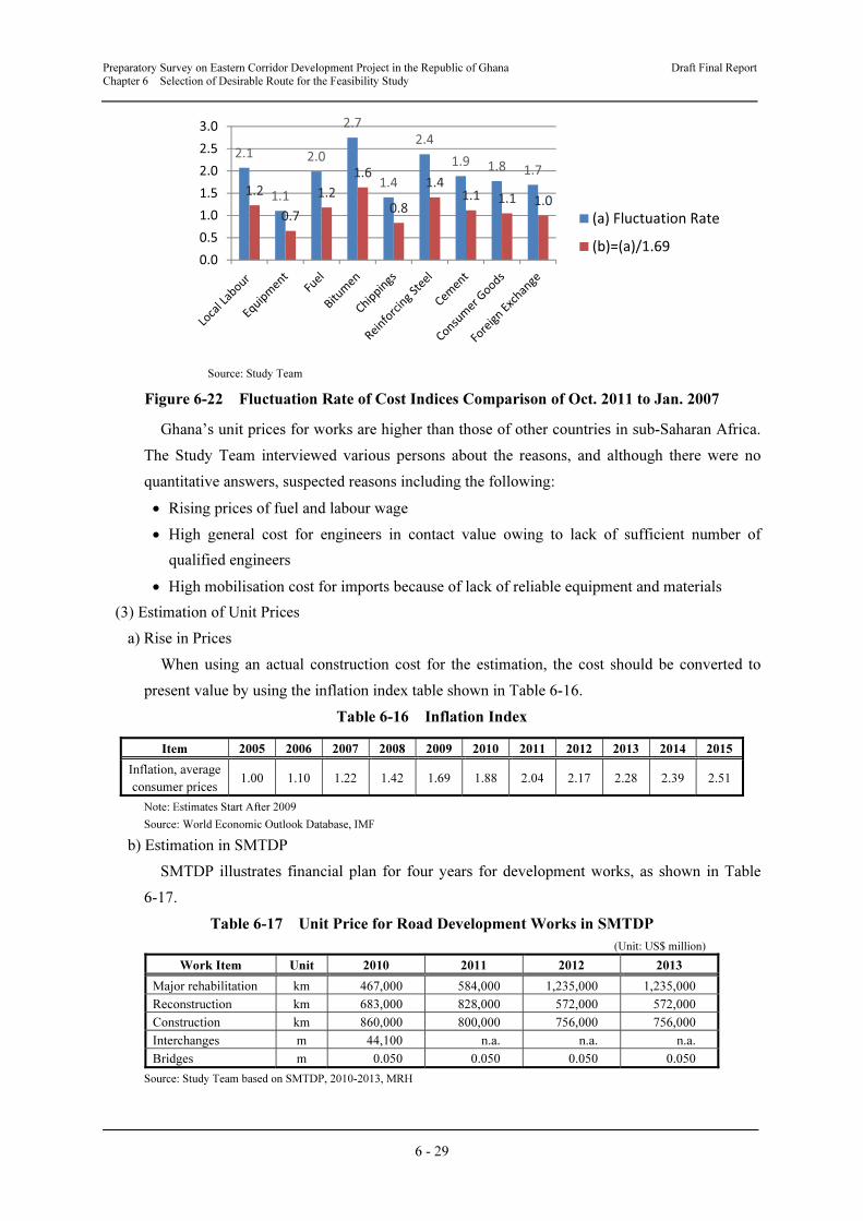
Indices up to the end of 2011 were available on the MRH’s web-site. The blue bar in Figure
6-22 shows the ratio of the indices in October 2011 to those in January 2007. The rise in prices
during this period is approximately estimated to be 1.67 based on the World Economic Outlook
Database (IMF). The brown bars (marked (b) in the figure) express the proportion of the
number on the blue bar divided by 1.69 (fluctuation of foreign exchange rate). Many indices
rose by more than the foreign exchange index.
In this report, the construction cost is estimated based on interviews, the previous JICA study
report, and the Eastern Corridor project report, taking into consideration of the rise in prices.
-
100
200
300
400
500
600
700
800
900
1,000
1980
1982
1984
1986
1988
1990
1992
1994
1996
1998
2000
2002
2004
2006
2008
Ghana
Burkina Faso
Cote d'Ivore
Togo
(Unit: Index)
0
2
4
6
8
10
12
14
16
18
20
1980
1982
1984
1986
1988
1990
1992
1994
1996
1998
2000
2002
2004
2006
2008
GDP Constant
GDP Current
(Unit: GHS billion)
Preparatory Survey on Eastern Corridor Development Project in the Republic of Ghana Draft Final Report Chapter 6 Selection of Desirable Route for the Feasibility Study
6 - 29
Source: Study Team
Figure 6-22 Fluctuation Rate of Cost Indices Comparison of Oct. 2011 to Jan. 2007
Ghana’s unit prices for works are higher than those of other countries in sub-Saharan Africa.
The Study Team interviewed various persons about the reasons, and although there were no
quantitative answers, suspected reasons including the following:
• Rising prices of fuel and labour wage
• High general cost for engineers in contact value owing to lack of sufficient number of
qualified engineers
• High mobilisation cost for imports because of lack of reliable equipment and materials
(3) Estimation of Unit Prices
a) Rise in Prices
When using an actual construction cost for the estimation, the cost should be converted to
present value by using the inflation index table shown in Table 6-16.
Table 6-16 Inflation Index
Item 2005 2006 2007 2008 2009 2010 2011 2012 2013 2014 2015
Inflation, average
consumer prices 1.00 1.10 1.22 1.42 1.69 1.88 2.04 2.17 2.28 2.39 2.51
Note: Estimates Start After 2009
Source: World Economic Outlook Database, IMF
b) Estimation in SMTDP
SMTDP illustrates financial plan for four years for development works, as shown in Table
6-17.
Table 6-17 Unit Price for Road Development Works in SMTDP
(Unit: US$ million)
Work Item Unit 2010 2011 2012 2013
Major rehabilitation km 467,000 584,000 1,235,000 1,235,000
Reconstruction km 683,000 828,000 572,000 572,000
Construction km 860,000 800,000 756,000 756,000
Interchanges m 44,100 n.a. n.a. n.a.
Bridges m 0.050 0.050 0.050 0.050
Source: Study Team based on SMTDP, 2010-2013, MRH
2.1
1.1
2.0
2.7
1.4
2.4
1.9 1.8 1.7
1.2
0.7
1.2
1.6
0.8
1.41.1 1.1 1.0
0.0
0.5
1.0
1.5
2.0
2.5
3.0
(a) Fluctuation Rate
(b)=(a)/1.69
Preparatory Survey on Eastern Corridor Development Project in the Republic of Ghana Draft Final Report Chapter 6 Selection of Desirable Route for the Feasibility Study
6 - 30
c) Road Construction Cost
1) Construction
Table 6-18 shows the construction unit price for each surface type under the GHA. The
revised unit price is that converted to the value as of 2012 using the inflation index shown in
Table 6-16. The construction unit price shown in Table 6-17 is less than the paved road
construction cost in Table 6-18, and is assumed to be the average price for all surface types.
Table 6-18 Unit Price for Road Construction
(Unit: US$ million)
Work Item Unit
Unit Price Revised Unit Price
Source 1 Source 2 Source 1 Source 2
as of 2005 as of 2008-2009 as of 2012 as of 2012
Gravel construction km 200,000 359,500 434,000 502,000
Paved construction with A/C km 500,000 1,250,000 1,090,000 1,740,000
Paved construction DBST km 300,000 785,000 651,000 1,095,000
Source-1: Statistical and Analytical Report (2000-2009), October 2011, MRH, MoT, and GSS
Source-2: Eastern Corridor Programme Preparatory Survey, 2010, JICA
The construction cost for the Eastern Corridor (N2) is estimated by the GHA for each lot as
shown in Table 6-19. The section of the Study (Asutsuare Jct. – Asikuma Jct.) is part of Lot 1,
but a 2-lane road is planned in this section, and so Lot 1’s unit price should not be used without
modification.
Table 6-19 Construction Cost of N2
Section Length
(km)
Cost
(US$ million)
Cost/Length
(US$ million)Remarks
Lot 1 Tema Jct. – Asikuma Jct. 91.0 145 1.70 Including 6- lane section (20 km) and
4-lane section (5 km)
Lot 2 Asikuma Jct. – Pose Cement 147.2 230 1.56 2 lanes (undecided)
Lot 3 Pose Cement – Nkwata 78.2 77 0.98 2 lanes upgrade to BST from gravel
Lot 4 Nkwata – Damanko 70.0 120 1.71 2 lanes upgrade to BST from gravel
Lot 5 Damanko – Yendi 86.0 165 1.92 2 lanes upgrade to BST from gravel
Lot 6 Yendi – Nakpanduri 123.2 245 1.99 2 lanes (undecided)
Lot 7 Nakpanduri – Kukungugu 100.0 200 2.00 2 lanes (undecided)
Note: Cost of lot is after reduction of cost of flyover, interchange and Adomi Bridge.
Source: Eastern Corridor Programme Preparatory Survey, 2010, JICA
2) Upgrade and Reconstruction
Table 6-20 shows unit prices for upgrade and reconstruction. These works are frequently
implemented, and the data are considered to be valid for actual activities. However, if large-
scale embankment works are required to raise the road level on a sag section, these data are not
suitable, as some drainage structures have inadequate capacity and need to be replaced. The
reconstruction including elevation of sag section and replacement of drainages is estimated
referring to the N8 Rehabilitation Plan22 (US$1.25 million/km, as of 2008).
According to the GHA, road reconstruction/construction project (75 km of asphalt concrete
pavement for 2-lanes road) between Kumasi and Techiman on the Central Corridor was
completed in 2011 founded by EU, and the total contracted amount was EUR 47.29 million
(US$ 946,000/km).
22 N8 Rehabilitation Plan Basic Survey Report, Dec 2008, JICA
Preparatory Survey on Eastern Corridor Development Project in the Republic of Ghana Draft Final Report Chapter 6 Selection of Desirable Route for the Feasibility Study
6 - 31
Table 6-20 Unit Price of Upgrade and Reconstruction
(Unit: US$/km)
Work Item Year GHA DFR
Upgrading to bituminous surface treatment 2012 217,300 220,000
Asphalt overlay 2012 281,800 -
Reconstruction 2012 572,000 350,000
Source: GHA, DFR
3) Replacement of Black Cotton Soil
Black cotton soil is thought to be distributed in the Study Area. This black cotton soil is not
suitable for road sub-bases because its volume is greatly affected by water, thus damaging the
road surface. If the road must be aligned over black cotton soil, the soil will need to be replaced
by a suitable material. The cost of replacement is estimated based on the GHA’s works rate with
the material price accounting for the majority. In the second stage of the Study, the plan for
procuring material will be carefully examined.
Table 6-21 Unit Price of Replacing Black Cotton Soil23
(Unit: GHS)
Work Item Unit Quantity Unit Cost Cost
Excavate unsuitable material m3 1.0 7.81 7.81
Filling and compact material from
borrow pits (sand)
m3 1.0 24.73 24.73
Total 32.54
Note: Referring to the unit price of the material for spot maintenance in DFR.
Source: Survey Team
4) Summary
The unit price used for estimation in the first stage of the Study is summarised in Table 6-22.
i) Construction
Comparing the prices of N2 Lot2 and prices of A/C paved road in Table 6-18, the
construction price is between US$0.76 million and US$1.80 million/km (2012 price). The
project site is easily accessible from Accra and Tema, and there are some quarry sites nearby.
Thus, the construction unit price is estimated to be US$1.4 million/km considering lower
haulage and availability of cheaper aggregates.
ii) Upgrade and Reconstruction
The unit price for reconstruction of ordinary road section is estimated to be US$572,000/km
(GHA’s unit price 2012). There is a possibility to raise unit price in case of relatively larger
scale works than the above mentioned reconstruction of ordinary road sections, referring to unit
price of the Kumasi and Techiman road project.
iii) Replacement of Black Cotton Soil
As shown in Table 6-22, the cost is estimated to be US$17/m324.
23 Works rate includes profit and margin, but does not include the cost of General Item and Contingency. 24 Exchange rate: GHS 1 = US$0.535 as of 1st May 2012.
Preparatory Survey on Eastern Corridor Development Project in the Republic of Ghana Draft Final Report Chapter 6 Selection of Desirable Route for the Feasibility Study
6 - 32
Table 6-22 Calculation of Unit Price for Estimation
Item Unit
Unit Price
(US$)
Inflation rate
Revised
Unit Price
(US$)
Adoption
(US$)
1. Construction cost km - - - 1,400,000
SMTDP 2012 756,000 1.00 756,000
GHA's unit price 2005 500,000 2.17 1,090,000
GHA's unit price 2008-09 1,250,000 1.40 1,740,000
N2 report 2010 1,560,000 1.15 1,800,000
2. Upgrade/reconstruction km - - - 572,000
GHA's unit price 2012 572,000 1.00 572,000
Kumasi-Techiman Project 2011 1,002,000 1.06 1,060,000
3. Black cotton soil replacement m3 - - - 17
Source: Survey Team
d) Bridge Construction
1) Bridge across Volta River
The bridge across the Volta River is unique in Ghana because of its long length (over 600 m)
and span (over 60 m), and useful local information is not available. There seems to be no
contractor in Ghana with the capability to construct such a bridge, or a factory for making the
superstructure.
The Study Team estimated the construction cost to choose among alternatives considering
estimations in Japan and the cost of other bridges with type in Ghana during the first stage of
the Study, and will survey and estimate detailed costs for the selected option in the second stage
of the Study.
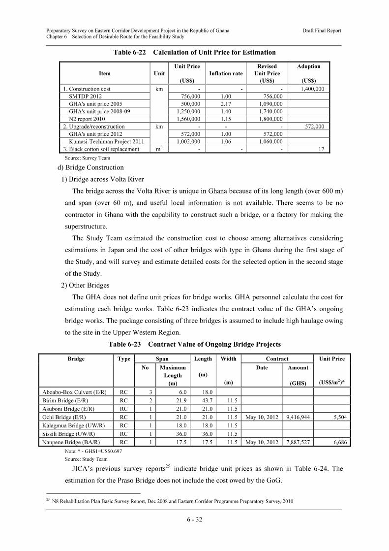
2) Other Bridges
The GHA does not define unit prices for bridge works. GHA personnel calculate the cost for
estimating each bridge works. Table 6-23 indicates the contract value of the GHA’s ongoing
bridge works. The package consisting of three bridges is assumed to include high haulage owing
to the site in the Upper Western Region.
Table 6-23 Contract Value of Ongoing Bridge Projects
Bridge Type Span Length
(m)
Width
(m)
Contract Unit Price
(US$/m2)*
No Maximum
Length
(m)
Date Amount
(GHS)
Aboabo-Box Culvert (E/R) RC 3 6.0 18.0
Birim Bridge (E/R) RC 2 21.9 43.7 11.5
Asuboni Bridge (E/R) RC 1 21.0 21.0 11.5
Ochi Bridge (E/R) RC 1 21.0 21.0 11.5 May 10, 2012 9,416,944 5,504
Kalagmua Bridge (UW/R) RC 1 18.0 18.0 11.5
Sissili Bridge (UW/R) RC 1 36.0 36.0 11.5
Nanpene Bridge (BA/R) RC 1 17.5 17.5 11.5 May 10, 2012 7,887,527 6,686
Note: * - GHS1=US$0.697
Source: Study Team
JICA’s previous survey reports25 indicate bridge unit prices as shown in Table 6-24. The
estimation for the Praso Bridge does not include the cost owed by the GoG.
25 N8 Rehabilitation Plan Basic Survey Report, Dec 2008 and Eastern Corridor Programme Preparatory Survey, 2010
Preparatory Survey on Eastern Corridor Development Project in the Republic of Ghana Draft Final Report Chapter 6 Selection of Desirable Route for the Feasibility Study
6 - 33
Table 6-24 Estimation for Bridge Works in JICA’s Reports
Bridge Type Span Length
(m)
Width
(m)
Estimation Unit
Price
(US$/m2)
Remark
No. Length
(m)
Month/
year
Total
(US$)
Praso Bridge PC 3 48.0 98.0 12.0 May 2008 3,723,256 3,166 Under
construction
New Abay Bridge
(Ethiopia)
PC 3 145.0 303.0 10.2 June 2005 21,564,413 6,984 Japanese
Grant Aid
Source: Study Team
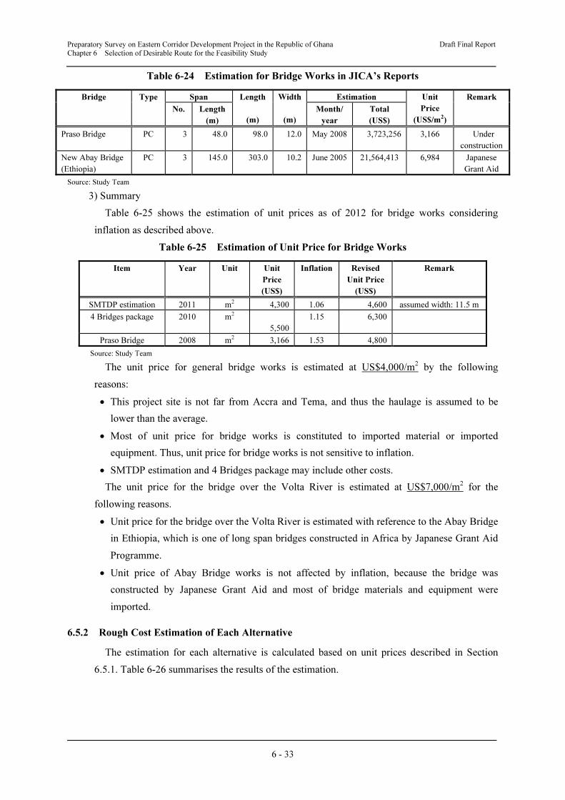
3) Summary
Table 6-25 shows the estimation of unit prices as of 2012 for bridge works considering
inflation as described above.
Table 6-25 Estimation of Unit Price for Bridge Works
Item Year Unit Unit
Price
(US$)
Inflation Revised
Unit Price
(US$)
Remark
SMTDP estimation 2011 m2 4,300 1.06 4,600 assumed width: 11.5 m
4 Bridges package 2010 m2
5,500
1.15 6,300
Praso Bridge 2008 m2 3,166 1.53 4,800
Source: Study Team
The unit price for general bridge works is estimated at US$4,000/m2 by the following
reasons:
• This project site is not far from Accra and Tema, and thus the haulage is assumed to be
lower than the average.
• Most of unit price for bridge works is constituted to imported material or imported
equipment. Thus, unit price for bridge works is not sensitive to inflation.
• SMTDP estimation and 4 Bridges package may include other costs.
The unit price for the bridge over the Volta River is estimated at US$7,000/m2 for the
following reasons.
• Unit price for the bridge over the Volta River is estimated with reference to the Abay Bridge
in Ethiopia, which is one of long span bridges constructed in Africa by Japanese Grant Aid
Programme.
• Unit price of Abay Bridge works is not affected by inflation, because the bridge was
constructed by Japanese Grant Aid and most of bridge materials and equipment were
imported.
6.5.2 Rough Cost Estimation of Each Alternative
The estimation for each alternative is calculated based on unit prices described in Section
6.5.1. Table 6-26 summarises the results of the estimation.
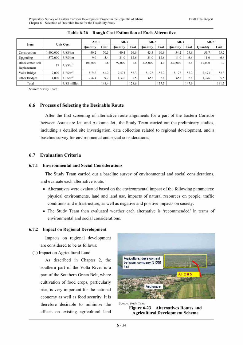
Preparatory Survey on Eastern Corridor Development Project in the Republic of Ghana Draft Final Report Chapter 6 Selection of Desirable Route for the Feasibility Study
6 - 34
Table 6-26 Rough Cost Estimation of Each Alternative
Item Unit Cost Alt. 1 Alt. 2 Alt. 3 Alt. 4 Alt. 5
Quantity Cost Quantity Cost Quantity Cost Quantity Cost Quantity Cost
Construction 1,400,000 US$/km 50.2 70.3 40.4 56.6 43.5 60.9 54.2 75.9 53.7 75.2
Upgrading 572,000 US$/km 9.0 5.4 21.0 12.6 21.0 12.6 11.0 6.6 11.0 6.6
Black cotton soil
Replacement 17 US$/m3
103,000 1.8 92,000 1.6 235,000 4.0 330,000 5.6 112,000 1.9
Volta Bridge 7,000 US$/m2 8,742 61.2 7,473 52.3 8,178 57.2 8,178 57.2 7,473 52.3
Other Bridges 4,000 US$/m2 2,424 9.7 1,376 5.5 655 2.6 655 2.6 1,376 5.5
Total US$ million 148.4 128.6 137.3 147.9 141.5
Source: Survey Team
6.6 Process of Selecting the Desirable Route
After the first screening of alternative route alignments for a part of the Eastern Corridor
between Asutsuare Jct. and Asikuma Jct., the Study Team carried out the preliminary studies,
including a detailed site investigation, data collection related to regional development, and a
baseline survey for environmental and social considerations.
6.7 Evaluation Criteria
6.7.1 Environmental and Social Considerations
The Study Team carried out a baseline survey of environmental and social considerations,
and evaluate each alternative route.
• Alternatives were evaluated based on the environmental impact of the following parameters:
physical environments, land and land use, impacts of natural resources on people, traffic
conditions and infrastructure, as well as negative and positive impacts on society.
• The Study Team then evaluated weather each alternative is ‘recommended’ in terms of
environmental and social considerations.
6.7.2 Impact on Regional Development
Impacts on regional development
are considered to be as follows:
(1) Impact on Agricultural Land
As described in Chapter 2, the
southern part of the Volta River is a
part of the Southern Green Belt, where
cultivation of food crops, particularly
rice, is very important for the national
economy as well as food security. It is
therefore desirable to minimise the
effects on existing agricultural land
Source: Study Team
Figure 6-23 Alternatives Routes and Agricultural Development Scheme
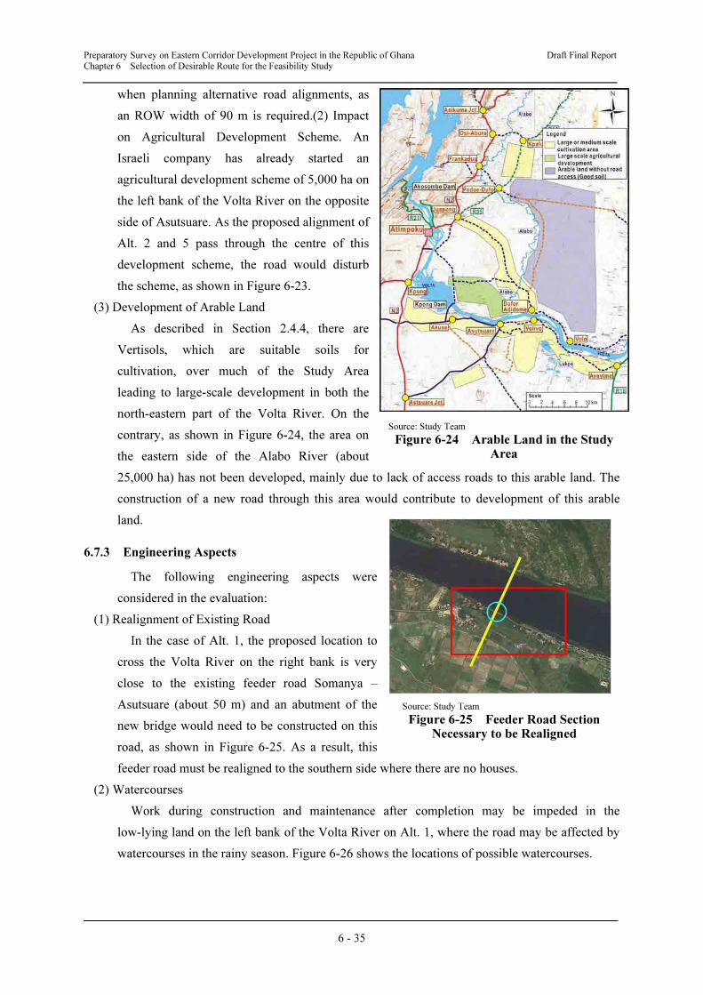
Preparatory Survey on Eastern Corridor Development Project in the Republic of Ghana Draft Final Report Chapter 6 Selection of Desirable Route for the Feasibility Study
6 - 35
when planning alternative road alignments, as
an ROW width of 90 m is required.(2) Impact
on Agricultural Development Scheme. An
Israeli company has already started an
agricultural development scheme of 5,000 ha on
the left bank of the Volta River on the opposite
side of Asutsuare. As the proposed alignment of
Alt. 2 and 5 pass through the centre of this
development scheme, the road would disturb
the scheme, as shown in Figure 6-23.
(3) Development of Arable Land
As described in Section 2.4.4, there are
Vertisols, which are suitable soils for
cultivation, over much of the Study Area
leading to large-scale development in both the
north-eastern part of the Volta River. On the
contrary, as shown in Figure 6-24, the area on
the eastern side of the Alabo River (about
25,000 ha) has not been developed, mainly due to lack of access roads to this arable land. The
construction of a new road through this area would contribute to development of this arable
land.
6.7.3 Engineering Aspects
The following engineering aspects were
considered in the evaluation:
(1) Realignment of Existing Road
In the case of Alt. 1, the proposed location to
cross the Volta River on the right bank is very
close to the existing feeder road Somanya –
Asutsuare (about 50 m) and an abutment of the
new bridge would need to be constructed on this
road, as shown in Figure 6-25. As a result, this
feeder road must be realigned to the southern side where there are no houses.
(2) Watercourses
Work during construction and maintenance after completion may be impeded in the
low-lying land on the left bank of the Volta River on Alt. 1, where the road may be affected by
watercourses in the rainy season. Figure 6-26 shows the locations of possible watercourses.
Source: Study Team
Figure 6-24 Arable Land in the Study Area
Source: Study Team
Figure 6-25 Feeder Road Section Necessary to be Realigned
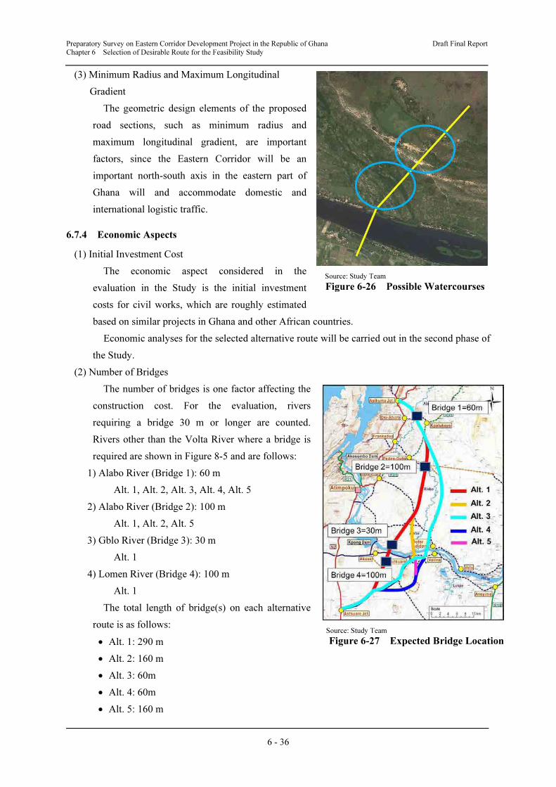
Preparatory Survey on Eastern Corridor Development Project in the Republic of Ghana Draft Final Report Chapter 6 Selection of Desirable Route for the Feasibility Study
6 - 36
(3) Minimum Radius and Maximum Longitudinal
Gradient
The geometric design elements of the proposed
road sections, such as minimum radius and
maximum longitudinal gradient, are important
factors, since the Eastern Corridor will be an
important north-south axis in the eastern part of
Ghana will and accommodate domestic and
international logistic traffic.
6.7.4 Economic Aspects
(1) Initial Investment Cost
The economic aspect considered in the
evaluation in the Study is the initial investment
costs for civil works, which are roughly estimated
based on similar projects in Ghana and other African countries.
Economic analyses for the selected alternative route will be carried out in the second phase of
the Study.
(2) Number of Bridges
The number of bridges is one factor affecting the
construction cost. For the evaluation, rivers
requiring a bridge 30 m or longer are counted.
Rivers other than the Volta River where a bridge is
required are shown in Figure 8-5 and are follows:
1) Alabo River (Bridge 1): 60 m
Alt. 1, Alt. 2, Alt. 3, Alt. 4, Alt. 5
2) Alabo River (Bridge 2): 100 m
Alt. 1, Alt. 2, Alt. 5
3) Gblo River (Bridge 3): 30 m
Alt. 1
4) Lomen River (Bridge 4): 100 m
Alt. 1
The total length of bridge(s) on each alternative
route is as follows:
• Alt. 1: 290 m
• Alt. 2: 160 m
• Alt. 3: 60m
• Alt. 4: 60m
• Alt. 5: 160 m
Source: Study Team
Figure 6-27 Expected Bridge Location
Source: Study Team
Figure 6-26 Possible Watercourses
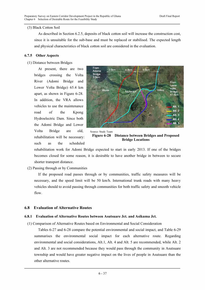
Preparatory Survey on Eastern Corridor Development Project in the Republic of Ghana Draft Final Report Chapter 6 Selection of Desirable Route for the Feasibility Study
6 - 37
(3) Black Cotton Soil
As described in Section 6.2.5, deposits of black cotton soil will increase the construction cost,
since it is unsuitable for the sub-base and must be replaced or stabilised. The expected length
and physical characteristics of black cotton soil are considered in the evaluation.
6.7.5 Other Aspects
(1) Distance between Bridges
At present, there are two
bridges crossing the Volta
River (Adomi Bridge and
Lower Volta Bridge) 65.4 km
apart, as shown in Figure 6-28.
In addition, the VRA allows
vehicles to use the maintenance
road of the Kpong
Hydroelectric Dam. Since both
the Adomi Bridge and Lower
Volta Bridge are old,
rehabilitation will be necessary:
such as the scheduled
rehabilitation work for Adomi Bridge expected to start in early 2013. If one of the bridges
becomes closed for some reason, it is desirable to have another bridge in between to secure
shorter transport distance.
(2) Passing through or by Communities
If the proposed road passes through or by communities, traffic safety measures will be
necessary, and the speed limit will be 50 km/h. International trunk roads with many heavy
vehicles should to avoid passing through communities for both traffic safety and smooth vehicle
flow.
6.8 Evaluation of Alternative Routes
6.8.1 Evaluation of Alternative Routes between Asutsuare Jct. and Asikuma Jct.
(1) Comparison of Alternative Routes based on Environmental and Social Consideration
Tables 6-27 and 6-28 compare the potential environmental and social impact, and Table 6-29
summarises the environmental social impact for each alternative route. Regarding
environmental and social considerations, Alt.1, Alt. 4 and Alt. 5 are recommended, while Alt. 2
and Alt. 3 are not recommended because they would pass through the community in Asutsuare
township and would have greater negative impact on the lives of people in Asutsuare than the
other alternative routes.
Source: Study Team
Figure 6-28 Distance between Bridges and Proposed Bridge Locations
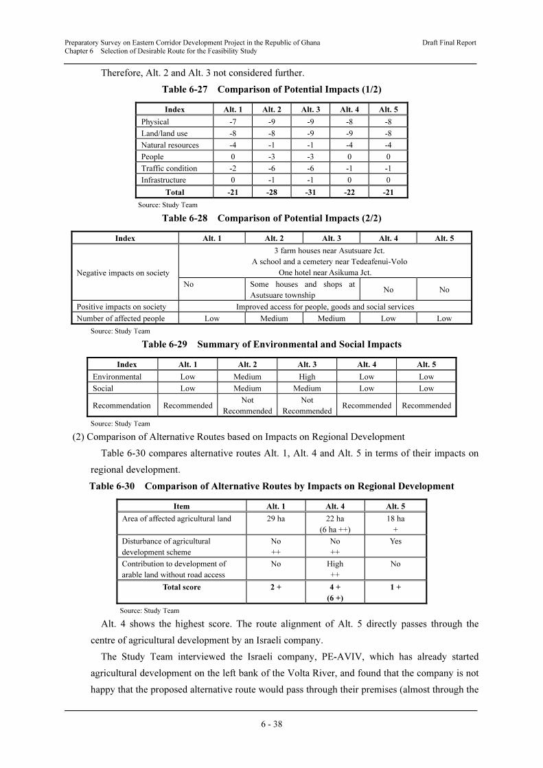
Preparatory Survey on Eastern Corridor Development Project in the Republic of Ghana Draft Final Report Chapter 6 Selection of Desirable Route for the Feasibility Study
6 - 38
Therefore, Alt. 2 and Alt. 3 not considered further.
Table 6-27 Comparison of Potential Impacts (1/2)
Index Alt. 1 Alt. 2 Alt. 3 Alt. 4 Alt. 5
Physical -7 -9 -9 -8 -8
Land/land use -8 -8 -9 -9 -8
Natural resources -4 -1 -1 -4 -4
People 0 -3 -3 0 0
Traffic condition -2 -6 -6 -1 -1
Infrastructure 0 -1 -1 0 0
Total -21 -28 -31 -22 -21
Source: Study Team
Table 6-28 Comparison of Potential Impacts (2/2)
Index Alt. 1 Alt. 2 Alt. 3 Alt. 4 Alt. 5
Negative impacts on society
3 farm houses near Asutsuare Jct.
A school and a cemetery near Tedeafenui-Volo
One hotel near Asikuma Jct.
No Some houses and shops at
Asutsuare township No No
Positive impacts on society Improved access for people, goods and social services
Number of affected people Low Medium Medium Low Low
Source: Study Team
Table 6-29 Summary of Environmental and Social Impacts
Index Alt. 1 Alt. 2 Alt. 3 Alt. 4 Alt. 5
Environmental Low Medium High Low Low
Social Low Medium Medium Low Low
Recommendation Recommended Not
Recommended
Not
RecommendedRecommended Recommended
Source: Study Team
(2) Comparison of Alternative Routes based on Impacts on Regional Development
Table 6-30 compares alternative routes Alt. 1, Alt. 4 and Alt. 5 in terms of their impacts on
regional development.
Table 6-30 Comparison of Alternative Routes by Impacts on Regional Development
Item Alt. 1 Alt. 4 Alt. 5
Area of affected agricultural land 29 ha 22 ha
(6 ha ++)
18 ha
+
Disturbance of agricultural
development scheme
No
++
No
++
Yes
Contribution to development of
arable land without road access
No High
++
No
Total score 2 + 4 +
(6 +)
1 +
Source: Study Team
Alt. 4 shows the highest score. The route alignment of Alt. 5 directly passes through the
centre of agricultural development by an Israeli company.
The Study Team interviewed the Israeli company, PE-AVIV, which has already started
agricultural development on the left bank of the Volta River, and found that the company is not
happy that the proposed alternative route would pass through their premises (almost through the
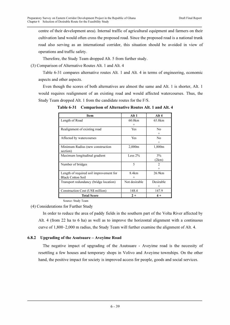
Preparatory Survey on Eastern Corridor Development Project in the Republic of Ghana Draft Final Report Chapter 6 Selection of Desirable Route for the Feasibility Study
6 - 39
centre of their development area). Internal traffic of agricultural equipment and farmers on their
cultivation land would often cross the proposed road. Since the proposed road is a national trunk
road also serving as an international corridor, this situation should be avoided in view of
operations and traffic safety.
Therefore, the Study Team dropped Alt. 5 from further study.
(3) Comparison of Alternative Routes Alt. 1 and Alt. 4
Table 6-31 compares alternative routes Alt. 1 and Alt. 4 in terms of engineering, economic
aspects and other aspects.
Even though the scores of both alternatives are almost the same and Alt. 1 is shorter, Alt. 1
would requires realignment of an existing road and would affected watercourses. Thus, the
Study Team dropped Alt. 1 from the candidate routes for the F/S.
Table 6-31 Comparison of Alternative Routes Alt. 1 and Alt. 4
Item Alt 1 Alt 4
Length of Road 60.0km
+
65.8km
Realignment of existing road Yes No
+
Affected by watercourses Yes No
+
Minimum Radius (new construction
section)
2,000m
1,800m
Maximum longitudinal gradient Less 2% 3%
(2km)
Number of bridges 5 2
+
Length of required soil improvement for
Black Cotton Soil
8.4km
+
26.9km
Transport redundancy (bridge location) Not desirable
Desirable
+
Construction Cost (US$ million) 148.4 147.9
Total Score 2 + 4 +
Source: Study Team
(4) Considerations for Further Study
In order to reduce the area of paddy fields in the southern part of the Volta River affected by
Alt. 4 (from 22 ha to 6 ha) as well as to improve the horizontal alignment with a continuous
curve of 1,800–2,000 m radius, the Study Team will further examine the alignment of Alt. 4.
6.8.2 Upgrading of the Asutsuare – Aveyime Road
The negative impact of upgrading of the Asutsuare - Aveyime road is the necessity of
resettling a few houses and temporary shops in Volivo and Aveyime townships. On the other
hand, the positive impact for society is improved access for people, goods and social services.
Preparatory Survey on Eastern Corridor Development Project in the Republic of Ghana Draft Final Report Chapter 6 Selection of Desirable Route for the Feasibility Study
6 - 40
6.9 Results of Evaluation and Proposed Alternative for the Feasibility Study
6.9.1 Road Section between Asutsuare Jct. and Asikuma Jct.
(1) The First Workshop
The first Workshop was held on 18th May 2012, inviting various stakeholders listed below,
to discuss the priorities of alternative routes for selecting the highest priority route for carrying
out the feasibility study in the second stage of the Study. However, the workshop was unable to
select a particular alternative for the feasibility.
List of Participating Organisations
• Ministry of Roads and Highways
• GHA
• Department of Feeder Roads (DFR)
• JICA Ghana Office
• Ministry of Finance and Economic Planning (MoFEP)
• Ministry of Transport (MoTr)
• European Union (EU)
• Millennium Development Authority (MiDA)
• Motor Transport Unit (MTU) of Ghana Police Service
• Regional Coordinating Council, Eastern Region
• National Planning Development Commission (NPDC)
• National Road Safety Commission (NRSC)
• JICA Study Team
• Local consultant (Associated Consultant)
(2) Further Discussions with GHA
Since a particular alternative for the feasibility study could not be selected in the First
Workshop, the Study Team and the GHA held further discussions. At the meeting held on 1st
June, 2012, the GHA finally agreed to select Alt. 4 for the F/S.
6.9.2 Road Section between Asutsuare and Aveyime
Based on the discussion, the GHA agreed with the idea of the Study Team to mainly follow
the present alignment for the improved road section between Asutsuare and Aveyime, but a
typical cross section with the inter-regional road should be adopted even in townships.
CHAPTER 7
PRELIMINARY DESIGN FOR
CONSTRUCTION OF ROAD
BETWEEN ASUTSUARE JCT.
AND ASIKUMA JCT.
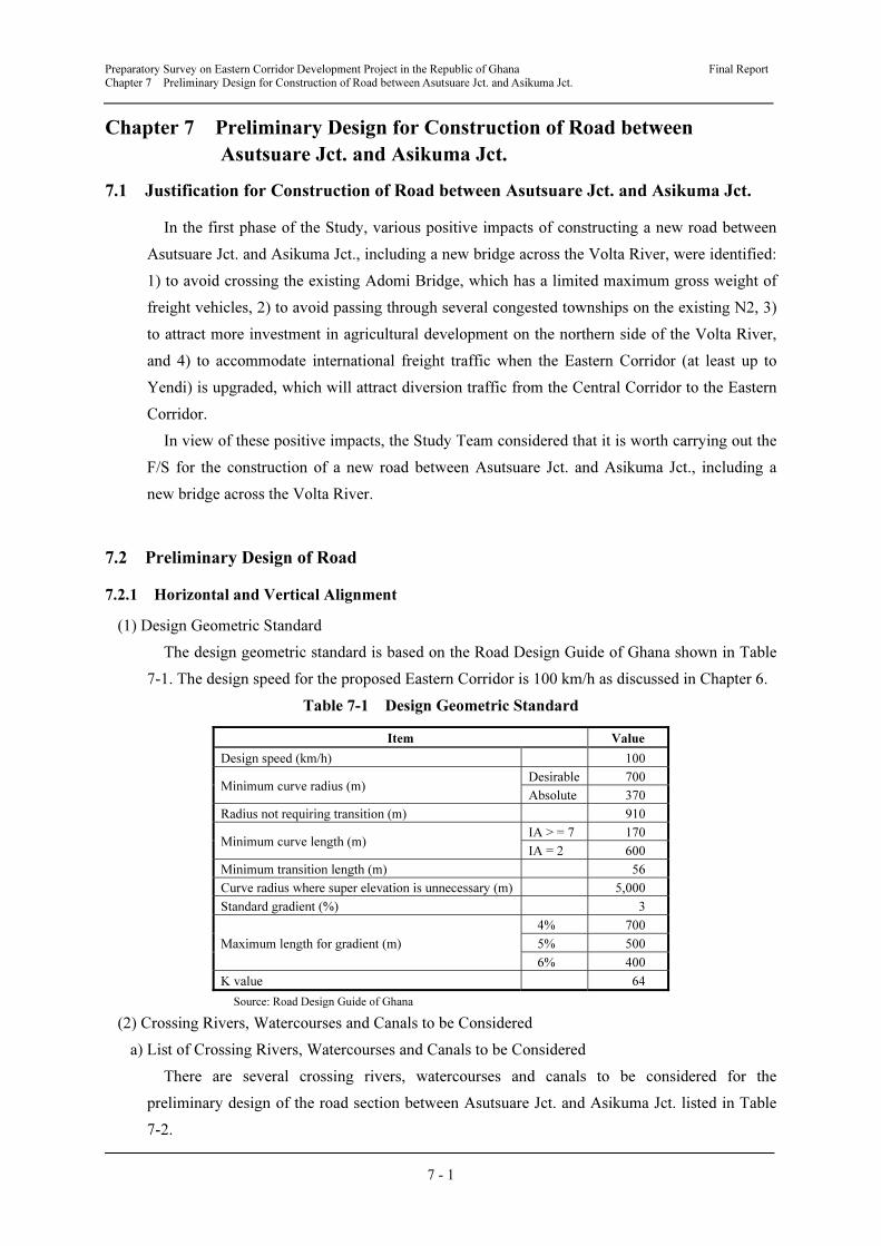
Preparatory Survey on Eastern Corridor Development Project in the Republic of Ghana Final Report
Chapter 7 Preliminary Design for Construction of Road between Asutsuare Jct. and Asikuma Jct.
7 - 1
Chapter 7 Preliminary Design for Construction of Road between
Asutsuare Jct. and Asikuma Jct.
7.1 Justification for Construction of Road between Asutsuare Jct. and Asikuma Jct.
In the first phase of the Study, various positive impacts of constructing a new road between
Asutsuare Jct. and Asikuma Jct., including a new bridge across the Volta River, were identified:
1) to avoid crossing the existing Adomi Bridge, which has a limited maximum gross weight of
freight vehicles, 2) to avoid passing through several congested townships on the existing N2, 3)
to attract more investment in agricultural development on the northern side of the Volta River,
and 4) to accommodate international freight traffic when the Eastern Corridor (at least up to
Yendi) is upgraded, which will attract diversion traffic from the Central Corridor to the Eastern
Corridor.
In view of these positive impacts, the Study Team considered that it is worth carrying out the
F/S for the construction of a new road between Asutsuare Jct. and Asikuma Jct., including a
new bridge across the Volta River.
7.2 Preliminary Design of Road
7.2.1 Horizontal and Vertical Alignment
(1) Design Geometric Standard
The design geometric standard is based on the Road Design Guide of Ghana shown in Table
7-1. The design speed for the proposed Eastern Corridor is 100 km/h as discussed in Chapter 6.
Table 7-1 Design Geometric Standard
Item Value
Design speed (km/h) 100
Minimum curve radius (m) Desirable 700
Absolute 370
Radius not requiring transition (m) 910
Minimum curve length (m) IA > = 7 170
IA = 2 600
Minimum transition length (m) 56
Curve radius where super elevation is unnecessary (m) 5,000
Standard gradient (%) 3
Maximum length for gradient (m)
4% 700
5% 500
6% 400
K value 64
Source: Road Design Guide of Ghana
(2) Crossing Rivers, Watercourses and Canals to be Considered
a) List of Crossing Rivers, Watercourses and Canals to be Considered
There are several crossing rivers, watercourses and canals to be considered for the
preliminary design of the road section between Asutsuare Jct. and Asikuma Jct. listed in Table
7-2.
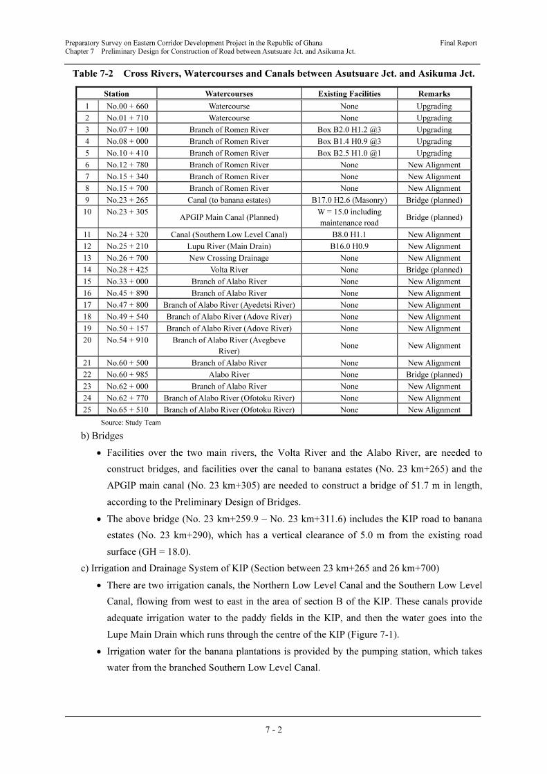
Preparatory Survey on Eastern Corridor Development Project in the Republic of Ghana Final Report
Chapter 7 Preliminary Design for Construction of Road between Asutsuare Jct. and Asikuma Jct.
7 - 2
Table 7-2 Cross Rivers, Watercourses and Canals between Asutsuare Jct. and Asikuma Jct.
Station Watercourses Existing Facilities Remarks
1 No.00 + 660 Watercourse None Upgrading
2 No.01 + 710 Watercourse None Upgrading
3 No.07 + 100 Branch of Romen River Box B2.0 H1.2 @3 Upgrading
4 No.08 + 000 Branch of Romen River Box B1.4 H0.9 @3 Upgrading
5 No.10 + 410 Branch of Romen River Box B2.5 H1.0 @1 Upgrading
6 No.12 + 780 Branch of Romen River None New Alignment
7 No.15 + 340 Branch of Romen River None New Alignment
8 No.15 + 700 Branch of Romen River None New Alignment
9 No.23 + 265 Canal (to banana estates) B17.0 H2.6 (Masonry) Bridge (planned)
10 No.23 + 305 APGIP Main Canal (Planned)
W = 15.0 including
maintenance road Bridge (planned)
11 No.24 + 320 Canal (Southern Low Level Canal) B8.0 H1.1 New Alignment
12 No.25 + 210 Lupu River (Main Drain) B16.0 H0.9 New Alignment
13 No.26 + 700 New Crossing Drainage None New Alignment
14 No.28 + 425 Volta River None Bridge (planned)
15 No.33 + 000 Branch of Alabo River None New Alignment
16 No.45 + 890 Branch of Alabo River None New Alignment
17 No.47 + 800 Branch of Alabo River (Ayedetsi River) None New Alignment
18 No.49 + 540 Branch of Alabo River (Adove River) None New Alignment
19 No.50 + 157 Branch of Alabo River (Adove River) None New Alignment
20 No.54 + 910 Branch of Alabo River (Avegbeve
River) None New Alignment
21 No.60 + 500 Branch of Alabo River None New Alignment
22 No.60 + 985 Alabo River None Bridge (planned)
23 No.62 + 000 Branch of Alabo River None New Alignment
24 No.62 + 770 Branch of Alabo River (Ofotoku River) None New Alignment
25 No.65 + 510 Branch of Alabo River (Ofotoku River) None New Alignment
Source: Study Team
b) Bridges
• Facilities over the two main rivers, the Volta River and the Alabo River, are needed to
construct bridges, and facilities over the canal to banana estates (No. 23 km+265) and the
APGIP main canal (No. 23 km+305) are needed to construct a bridge of 51.7 m in length,
according to the Preliminary Design of Bridges.
• The above bridge (No. 23 km+259.9 – No. 23 km+311.6) includes the KIP road to banana
estates (No. 23 km+290), which has a vertical clearance of 5.0 m from the existing road
surface (GH = 18.0).
c) Irrigation and Drainage System of KIP (Section between 23 km+265 and 26 km+700)
• There are two irrigation canals, the Northern Low Level Canal and the Southern Low Level
Canal, flowing from west to east in the area of section B of the KIP. These canals provide
adequate irrigation water to the paddy fields in the KIP, and then the water goes into the
Lupe Main Drain which runs through the centre of the KIP (Figure 7-1).
• Irrigation water for the banana plantations is provided by the pumping station, which takes
water from the branched Southern Low Level Canal.
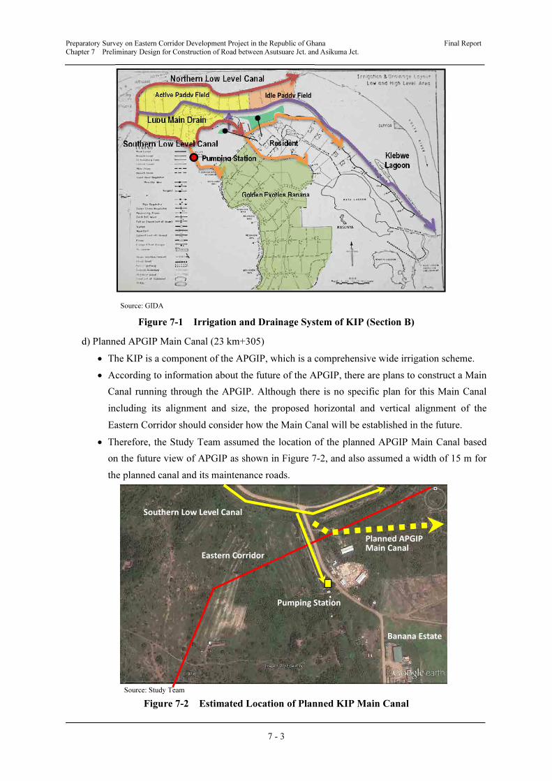
Preparatory Survey on Eastern Corridor Development Project in the Republic of Ghana Final Report
Chapter 7 Preliminary Design for Construction of Road between Asutsuare Jct. and Asikuma Jct.
7 - 3
Source: GIDA
Figure 7-1 Irrigation and Drainage System of KIP (Section B)
d) Planned APGIP Main Canal (23 km+305)
• The KIP is a component of the APGIP, which is a comprehensive wide irrigation scheme.
• According to information about the future of the APGIP, there are plans to construct a Main
Canal running through the APGIP. Although there is no specific plan for this Main Canal
including its alignment and size, the proposed horizontal and vertical alignment of the
Eastern Corridor should consider how the Main Canal will be established in the future.
• Therefore, the Study Team assumed the location of the planned APGIP Main Canal based
on the future view of APGIP as shown in Figure 7-2, and also assumed a width of 15 m for
the planned canal and its maintenance roads.
Source: Study Team
Figure 7-2 Estimated Location of Planned KIP Main Canal
Northern Low Level Canal
Klebwe Lagoon
Golden Exotics Banana
Pumping Station
Resident
Lupu Main Drain
Active Paddy Field
Southern Low Level Canal
Idle Paddy Field
Pumping Station
Eastern Corridor
Planned APGIP Main Canal
Southern Low Level Canal
Banana Estate
Preparatory Survey on Eastern Corridor Development Project in the Republic of Ghana Final Report
Chapter 7 Preliminary Design for Construction of Road between Asutsuare Jct. and Asikuma Jct.
7 - 4
(3) Crossing Roads to be Considered
a) List of Crossing Roads to be Considered
Crossing roads to be considered for the preliminary design of the road section between
Asutsuare Jct. and Asikuma Jct. are listed in Table 7-3.
Table 7-3 Crossing Roads between Asutsuare Jct. and Asikuma Jct.
Station Road Existing Facilities Remarks
1 No.00 + 000 National Road - 2 (N2) Intersection (A/C) Upgrading
2 No.11 + 050 Feeder Road W = 8.0 (Gravel) New Alignment
3 No.16 + 970 Feeder Road W = 6.0 (Gravel) New Alignment
4 No.23 + 290 KIP Road (to Banana Estates) W = 8.0 (Gravel) New Alignment
5 No.24 + 210 KIP Road W = 7.0 (Gravel) New Alignment
6 No.25 + 270 KIP Road W = 6.0 (Gravel) New Alignment
8 No. 27 + 534 2) Inter-regional Road (planned) 2) W = 11.3 (A/C) New Alignment
9 No.29 + 060 Feeder Road W = 6.5 (Gravel) New Alignment
10 No.48 + 600 Feeder Road W = 4.0 (Gravel) New Alignment
11 No.58 + 150 Regional Road - 95 (R95) W = 9.0 (Gravel) New Alignment
12 No.67 + 027 National Road - 2 (N2)
National Road - 5 (N5)
Intersection (Ac) New Alignment
Source: Study Team
b) KIP Road to Banana Estates
The location of the KIP road to the Golden Exotics Banana Estates is shown in Figure 7-2.
(4) Comparison of Horizontal Alignment
From the results of the topographic survey and the detailed site investigation after the first
Workshop held on 18th May 2012, the proposed horizontal alignment of the Eastern Corridor
was set based on the route of Alternative 4 (Alt. 4) as discussed in Chapter 6.
a) Section between KIP Paddy Fields and Northern Part of Volta River
The Study Team compared the original alignment, for which a desirable route was selected
by the first Workshop, and an alternative alignment in order to reduce the impact on the paddy
fields of the KIP in the southern part of the Volta River. The alternative alignment is
advantageous in terms of construction cost and traffic safety for agricultural traffic in the KIP.
The original alignment and alternative alignment are compared in Table 7-4 and Figure 7-3.
As a result, the location of the Volta River Bridge is set according to the alternative
alignment.
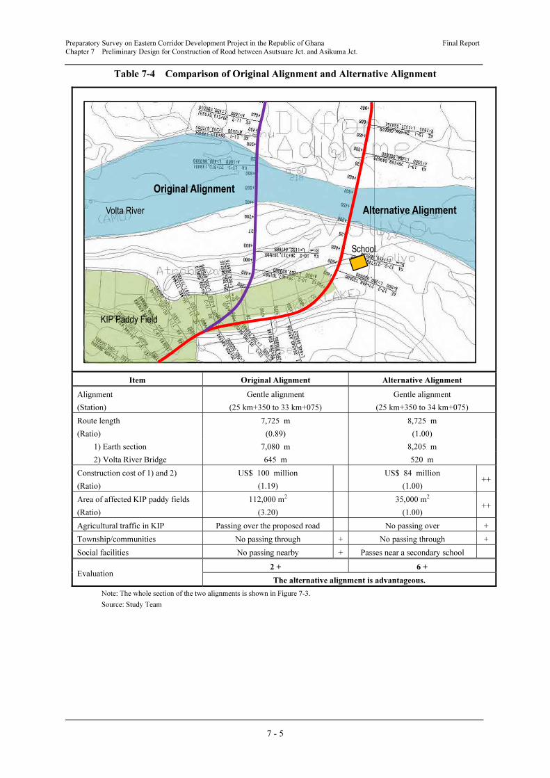
Preparatory Survey on Eastern Corridor Development Project in the Republic of Ghana Final Report
Chapter 7 Preliminary Design for Construction of Road between Asutsuare Jct. and Asikuma Jct.
7 - 5
Table 7-4 Comparison of Original Alignment and Alternative Alignment
Item Original Alignment Alternative Alignment
Alignment
(Station)
Gentle alignment
(25 km+350 to 33 km+075)
Gentle alignment
(25 km+350 to 34 km+075)
Route length
(Ratio)
7,725 m
(0.89)
8,725 m
(1.00)
1) Earth section 7,080 m 8,205 m
2) Volta River Bridge 645 m 520 m
Construction cost of 1) and 2)
(Ratio)
US$ 100 million
(1.19)
US$ 84 million
(1.00) ++
Area of affected KIP paddy fields
(Ratio)
112,000 m2
(3.20)
35,000 m2
(1.00) ++
Agricultural traffic in KIP Passing over the proposed road No passing over +
Township/communities No passing through + No passing through +
Social facilities No passing nearby + Passes near a secondary school
Evaluation 2 + 6 +
The alternative alignment is advantageous.
Note: The whole section of the two alignments is shown in Figure 7-3.
Source: Study Team
KIP Paddy Field
Volta River
School
Original Alignment
Alternative Alignment
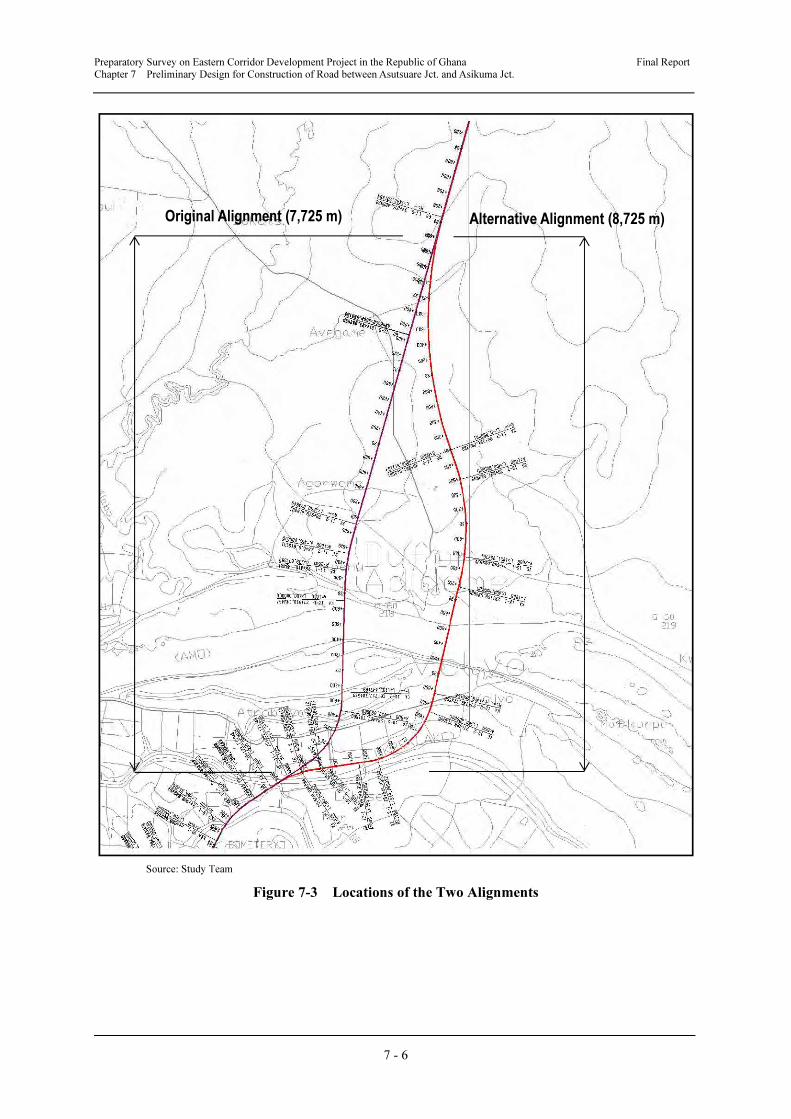
Preparatory Survey on Eastern Corridor Development Project in the Republic of Ghana Final Report
Chapter 7 Preliminary Design for Construction of Road between Asutsuare Jct. and Asikuma Jct.
7 - 6
Source: Study Team
Figure 7-3 Locations of the Two Alignments
Alternative Alignment (8,725 m) Original Alignment (7,725 m)
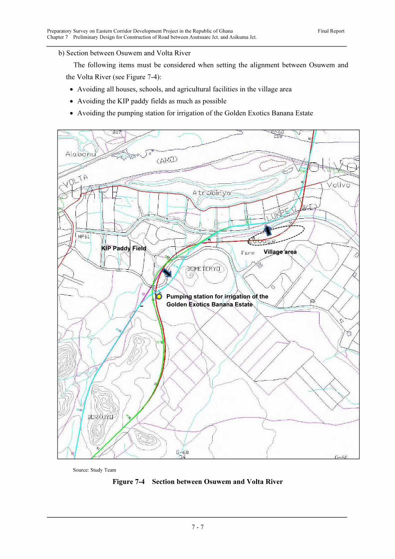
Preparatory Survey on Eastern Corridor Development Project in the Republic of Ghana Final Report
Chapter 7 Preliminary Design for Construction of Road between Asutsuare Jct. and Asikuma Jct.
7 - 7
b) Section between Osuwem and Volta River
The following items must be considered when setting the alignment between Osuwem and
the Volta River (see Figure 7-4):
• Avoiding all houses, schools, and agricultural facilities in the village area
• Avoiding the KIP paddy fields as much as possible
• Avoiding the pumping station for irrigation of the Golden Exotics Banana Estate
Source: Study Team
Figure 7-4 Section between Osuwem and Volta River
Pumping station for irrigation of the
Golden Exotics Banana Estate
Village area KIP Paddy Field
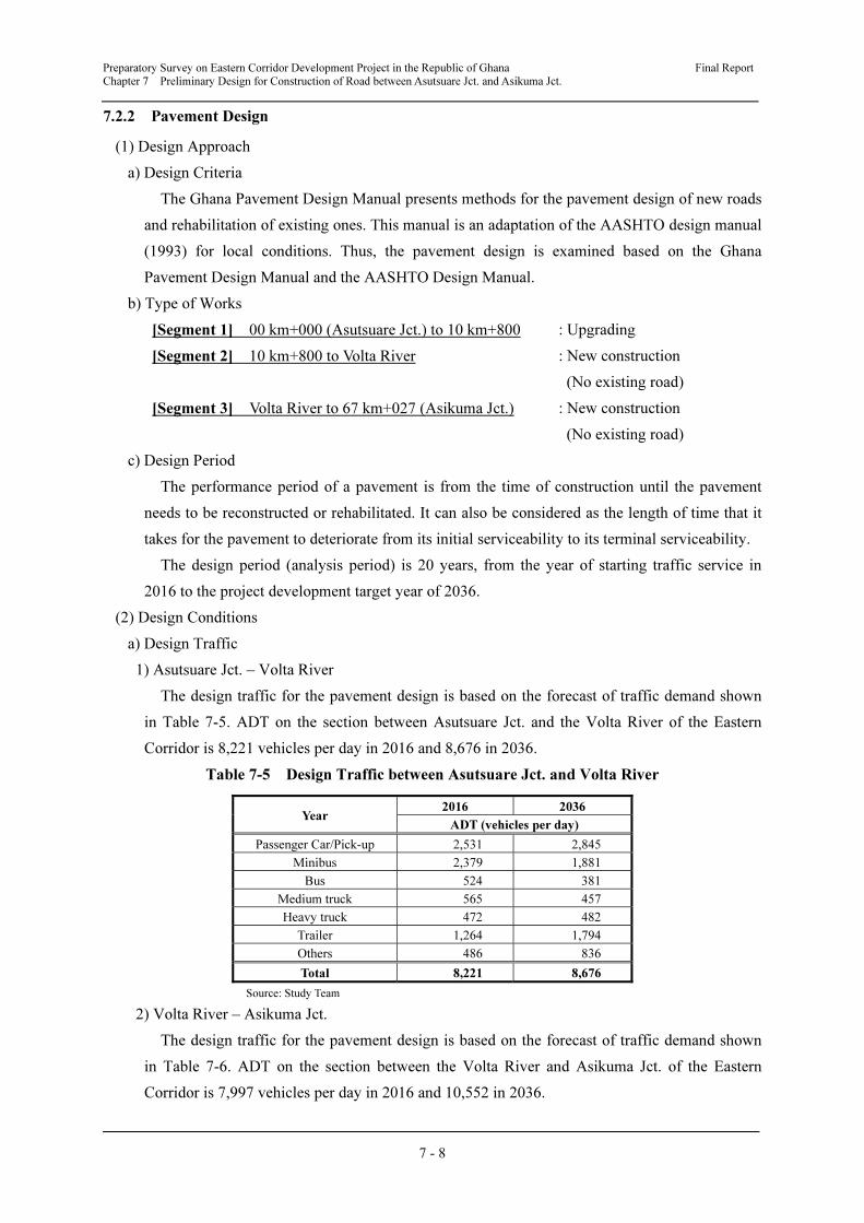
Preparatory Survey on Eastern Corridor Development Project in the Republic of Ghana Final Report
Chapter 7 Preliminary Design for Construction of Road between Asutsuare Jct. and Asikuma Jct.
7 - 8
7.2.2 Pavement Design
(1) Design Approach
a) Design Criteria
The Ghana Pavement Design Manual presents methods for the pavement design of new roads
and rehabilitation of existing ones. This manual is an adaptation of the AASHTO design manual
(1993) for local conditions. Thus, the pavement design is examined based on the Ghana
Pavement Design Manual and the AASHTO Design Manual.
b) Type of Works
[Segment 1] 00 km+000 (Asutsuare Jct.) to 10 km+800 : Upgrading
[Segment 2] 10 km+800 to Volta River : New construction
(No existing road)
[Segment 3] Volta River to 67 km+027 (Asikuma Jct.) : New construction
(No existing road)
c) Design Period
The performance period of a pavement is from the time of construction until the pavement
needs to be reconstructed or rehabilitated. It can also be considered as the length of time that it
takes for the pavement to deteriorate from its initial serviceability to its terminal serviceability.
The design period (analysis period) is 20 years, from the year of starting traffic service in
2016 to the project development target year of 2036.
(2) Design Conditions
a) Design Traffic
1) Asutsuare Jct. – Volta River
The design traffic for the pavement design is based on the forecast of traffic demand shown
in Table 7-5. ADT on the section between Asutsuare Jct. and the Volta River of the Eastern
Corridor is 8,221 vehicles per day in 2016 and 8,676 in 2036.
Table 7-5 Design Traffic between Asutsuare Jct. and Volta River
Year 2016 2036
ADT (vehicles per day)
Passenger Car/Pick-up 2,531 2,845
Minibus 2,379 1,881
Bus 524 381
Medium truck 565 457
Heavy truck 472 482
Trailer 1,264 1,794
Others 486 836
Total 8,221 8,676
Source: Study Team
2) Volta River – Asikuma Jct.
The design traffic for the pavement design is based on the forecast of traffic demand shown
in Table 7-6. ADT on the section between the Volta River and Asikuma Jct. of the Eastern
Corridor is 7,997 vehicles per day in 2016 and 10,552 in 2036.
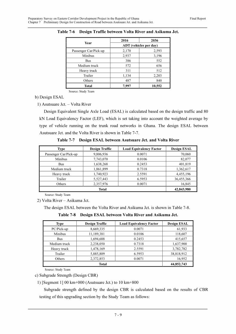
Preparatory Survey on Eastern Corridor Development Project in the Republic of Ghana Final Report
Chapter 7 Preliminary Design for Construction of Road between Asutsuare Jct. and Asikuma Jct.
7 - 9
Table 7-6 Design Traffic between Volta River and Asikuma Jct.
Year 2016 2036
ADT (vehicles per day)
Passenger Car/Pick-up 2,170 2,593
Minibus 2,937 3,196
Bus 386 552
Medium truck 572 656
Heavy truck 311 512
Trailer 1,134 2,203
Others 487 840
Total 7,997 10,552
Source: Study Team
b) Design ESAL
1) Asutsuare Jct. – Volta River
Design Equivalent Single Axle Load (ESAL) is calculated based on the design traffic and 80
kN Load Equivalency Factor (LEF), which is set taking into account the weighted average by
type of vehicle running on the trunk road networks in Ghana. The design ESAL between
Asutsuare Jct. and the Volta River is shown in Table 7-7.
Table 7-7 Design ESAL between Asutsuare Jct. and Volta River
Type Design Traffic Load Equivalency Factor Design ESAL
Passenger Car/Pick-up 9,806,936 0.0071 70,060
Minibus 7,743,070 0.0106 82,077
Bus 1,638,268 0.2453 401,819
Medium truck 1,861,899 0.7318 1,362,617
Heavy truck 1,740,923 2.5591 4,455,196
Trailer 5,527,443 6.5953 36,455,366
Others 2,357,976 0.0071 16,845
Total 42,843,980
Source: Study Team
2) Volta River – Asikuma Jct.
The design ESAL between the Volta River and Asikuma Jct. is shown in Table 7-8.
Table 7-8 Design ESAL between Volta River and Asikuma Jct.
Type Design Traffic Load Equivalency Factor Design ESAL
PC/Pick-up 8,669,335 0.0071 61,933
Minibus 11,189,381 0.0106 118,607
Bus 1,694,688 0.2453 415,657
Medium truck 2,238,050 0.7318 1,637,900
Heavy truck 1,478,169 2.5591 3,782,782
Trailer 5,885,809 6.5953 38,818,912
Others 2,372,853 0.0071 16,952
Total 44,852,743
Source: Study Team
c) Subgrade Strength (Design CBR)
1) [Segment 1] 00 km+000 (Asutsuare Jct.) to 10 km+800
Subgrade strength defined by the design CBR is calculated based on the results of CBR
testing of this upgrading section by the Study Team as follows:
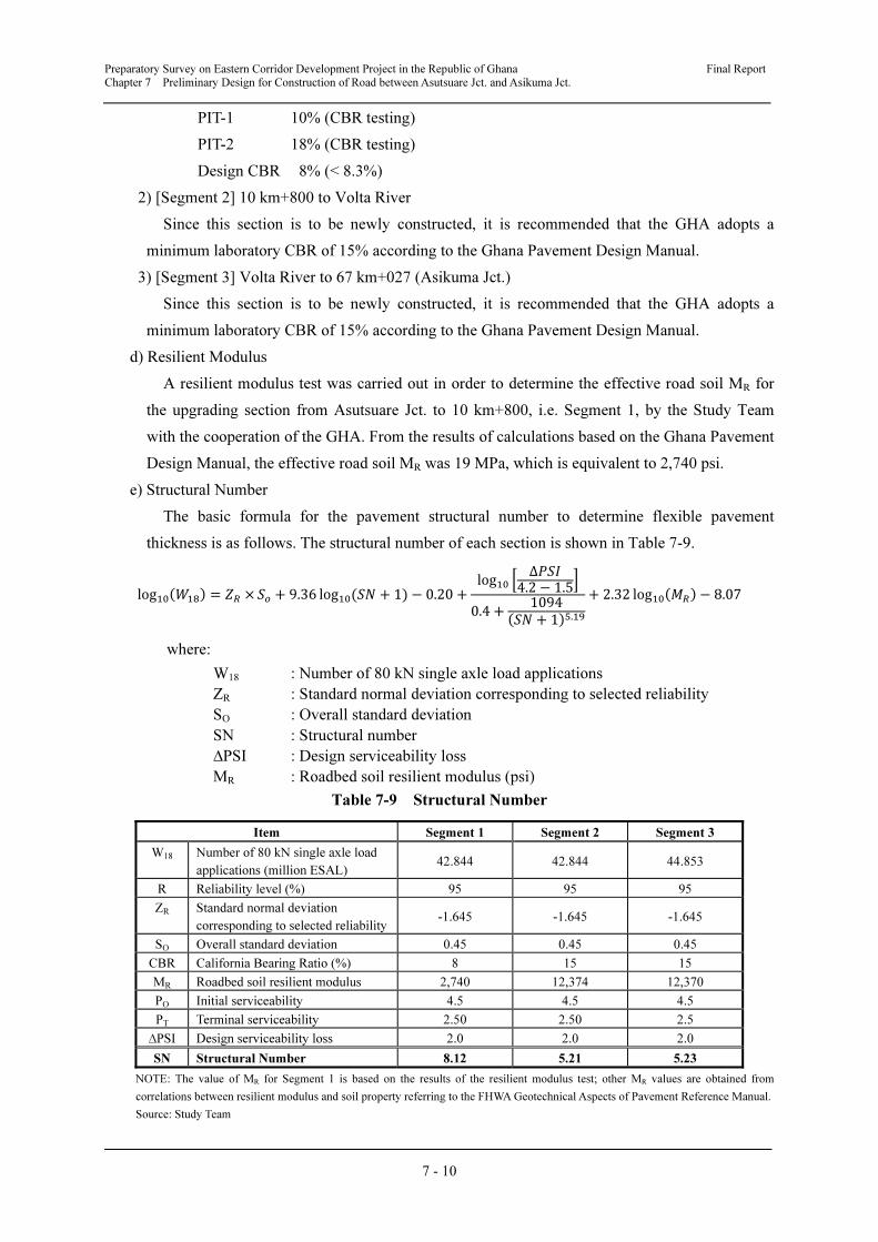
Preparatory Survey on Eastern Corridor Development Project in the Republic of Ghana Final Report
Chapter 7 Preliminary Design for Construction of Road between Asutsuare Jct. and Asikuma Jct.
7 - 10
PIT-1 10% (CBR testing)
PIT-2 18% (CBR testing)
Design CBR 8% (< 8.3%)
2) [Segment 2] 10 km+800 to Volta River
Since this section is to be newly constructed, it is recommended that the GHA adopts a
minimum laboratory CBR of 15% according to the Ghana Pavement Design Manual.
3) [Segment 3] Volta River to 67 km+027 (Asikuma Jct.)
Since this section is to be newly constructed, it is recommended that the GHA adopts a
minimum laboratory CBR of 15% according to the Ghana Pavement Design Manual.
d) Resilient Modulus
A resilient modulus test was carried out in order to determine the effective road soil MR for
the upgrading section from Asutsuare Jct. to 10 km+800, i.e. Segment 1, by the Study Team
with the cooperation of the GHA. From the results of calculations based on the Ghana Pavement
Design Manual, the effective road soil MR was 19 MPa, which is equivalent to 2,740 psi.
e) Structural Number
The basic formula for the pavement structural number to determine flexible pavement
thickness is as follows. The structural number of each section is shown in Table 7-9.
log������� = �� × �� + 9.36 log��(�� + 1) − 0.20 +
log�� � ∆�4.2 − 1.5
�
0.4 +1094
��� + 1��.��+ 2.32 log�����
�− 8.07
where:
W18 : Number of 80 kN single axle load applications
ZR : Standard normal deviation corresponding to selected reliability
SO : Overall standard deviation
SN : Structural number
∆PSI : Design serviceability loss
MR : Roadbed soil resilient modulus (psi)
Table 7-9 Structural Number
Item Segment 1 Segment 2 Segment 3
W18 Number of 80 kN single axle load
applications (million ESAL) 42.844 42.844 44.853
R Reliability level (%) 95 95 95
ZR Standard normal deviation
corresponding to selected reliability-1.645 -1.645 -1.645
SO Overall standard deviation 0.45 0.45 0.45
CBR California Bearing Ratio (%) 8 15 15
MR Roadbed soil resilient modulus 2,740 12,374 12,370
PO Initial serviceability 4.5 4.5 4.5
PT Terminal serviceability 2.50 2.50 2.5
∆PSI Design serviceability loss 2.0 2.0 2.0
SN Structural Number 8.12 5.21 5.23
NOTE: The value of MR for Segment 1 is based on the results of the resilient modulus test; other MR values are obtained from
correlations between resilient modulus and soil property referring to the FHWA Geotechnical Aspects of Pavement Reference Manual.
Source: Study Team
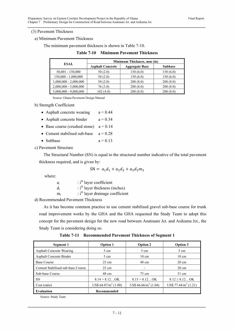
Preparatory Survey on Eastern Corridor Development Project in the Republic of Ghana Final Report
Chapter 7 Preliminary Design for Construction of Road between Asutsuare Jct. and Asikuma Jct.
7 - 11
(3) Pavement Thickness
a) Minimum Pavement Thickness
The minimum pavement thickness is shown in Table 7-10.
Table 7-10 Minimum Pavement Thickness
ESAL Minimum Thickness, mm (in)
Asphalt Concrete Aggregate Base Subbase
50,001 - 150,000 50 (2.0) 150 (6.0) 150 (6.0)
150,000 - 1,000,000 50 (2.0) 150 (6.0) 150 (6.0)
1,000,000 - 2,000,000 50 (2.0) 200 (8.0) 200 (8.0)
2,000,000 - 5,000,000 76 (3.0) 200 (8.0) 200 (8.0)
5,000,000 - 9,000,000 102 (4.0) 200 (8.0) 200 (8.0)
Source: Ghana Pavement Design Manual
b) Strength Coefficient
• Asphalt concrete wearing a = 0.44
• Asphalt concrete binder a = 0.34
• Base course (crushed stone) a = 0.14
• Cement stabilised sub-base a = 0.28
• Subbase a = 0.13
c) Pavement Structure
The Structural Number (SN) is equal to the structural number indicative of the total pavement
thickness required, and is given by:
SN = ���� + ���� + ������
where:
ai : ith layer coefficient
di : ith layer thickness (inches)
mi : ith layer drainage coefficient
d) Recommended Pavement Thickness
As it has become common practice to use cement stabilised gravel sub-base course for trunk
road improvement works by the GHA and the GHA requested the Study Team to adopt this
concept for the pavement design for the new road between Asutsuare Jct. and Asikuma Jct., the
Study Team is considering doing so.
Table 7-11 Recommended Pavement Thickness of Segment 1
Segment 1 Option 1 Option 2 Option 3
Asphalt Concrete Wearing 5 cm 5 cm 5 cm
Asphalt Concrete Binder 5 cm 10 cm 10 cm
Base Course 25 cm 40 cm 20 cm
Cement Stabilised sub-base Course 25 cm - 20 cm
Sub-base Course 48 cm 73 cm 51 cm
SN 8.14 > 8.12…OK 8.15 > 8.12…OK 8.12 ≥ 8.12…OK
Cost (ratio) US$ 64.07/m2 (1.00) US$ 66.66/m2 (1.04) US$ 77.44/m2 (1.21)
Evaluation Recommended
Source: Study Team
Preparatory Survey on Eastern Corridor Development Project in the Republic of Ghana Final Report
Chapter 7 Preliminary Design for Construction of Road between Asutsuare Jct. and Asikuma Jct.
7 - 12
Option 1 is recommended for the pavement thickness of Segment 1 for economic reasons as
well as greater durability against the weather thanks to its higher impermeability and strength of
sub-base course.
Table 7-12 Recommended Pavement Thickness of Segment 2
Segment 2 Option 1 Option 2 Option 3
Asphalt Concrete Wearing 5 cm 5 cm 5 cm
Asphalt Concrete Binder 5 cm 10 cm 10 cm
Base Course 20 cm 25 cm 20 cm
Cement Stabilised sub-base Course 24 cm - 20 cm
Sub-base Course - 35 cm -
SN 5.29 > 5.21…OK 5.38 > 5.21…OK 5.51 > 5.21…OK
Cost (ratio) US$ 57.29 /m2
(1.00) US$ 60.14 /m2 (1.05) US$ 71.93 /m2 (1.26)
Evaluation Recommended
Source: Study Team
Option 1 is recommended for the pavement thickness of Segment 2 for economic reasons as
well as greater durability against the weather thanks to its higher impermeability and strength of
sub-base course.
Table 7-13 Recommended Pavement Thickness of Segment 3
Segment 3 Option 1 Option 2 Option 3
Asphalt Concrete Wearing 5 cm 5 cm 5 cm
Asphalt Concrete Binder 5 cm 10 cm 10 cm
Base Course 20 cm 25 cm 20 cm
Cement Stabilised sub-base Course 24cm - 20 cm
Sub-base Course - 35 cm -
SN 5.29 > 5.23…OK 5.38 > 5.23…OK 5.51 > 5.23…OK
Cost (ratio) US$ 57.29 /m2
(1.00) US$ 60.14 /m2 (1.05) US$ 71.93 /m2 (1.26)
Evaluation Recommended
Source: Study Team
Option 1 is recommended for the pavement thickness of Segment 3 for economic reasons as
well as greater durability against the weather thanks to its higher impermeability and strength of
sub-base course.
7.2.3 Road Drainage
a) Maximum Discharge
The catchment area is obtained from 1/50,000 scale topographic maps, and the frequency of
occurrence for road culverts crossing the proposed road between Asutsuare Jct. and Asikuma Jct.
such as watercourses, branches of the Romen River and branches of the Alabo River is
determined as 10 years based on the Ghana Road Design Guide as shown in Table 7-14.
Preparatory Survey on Eastern Corridor Development Project in the Republic of Ghana Final Report
Chapter 7 Preliminary Design for Construction of Road between Asutsuare Jct. and Asikuma Jct.
7 - 13
Table 7-14 Frequency of Occurrence
Frequency of Occurrence (years) Application
5 General road drainage structures such as gutters, street gullies, etc.
10 Important drainage structures such as road crossing drainage
Source: Ghana Road Design Guide
Time of concentration (minutes) is calculated using the following Bransby-Williams formula
and the factor of this equation has been confirmed by the GHA:
�� =58.5 × �
��.� × ��.�
where:
L : Main stream length (km)
A : Catchment area (km2)
Se : Slope of main stream (m/km)
The maximum discharge (m3/sec) is calculated using the rational equation (run-off coefficient
is 0.2), and hence the minimum required inner size of road culverts is obtained as shown in
Table 7-15.
Table 7-15 Minimum Requirements for Road Culverts
Station Catchment
Area
Catchment
Length
Slope of
Main
Stream
Concentration
Time
Rainfall
Intensity
Maximum
Discharge
Minimum
Requirement
A (km2) L (km) Se (m/km) t (min) I10 (mm/hr) Q (m
3/sec) (m)
No.00 + 660 2.05 2.436 9.14 101.81 5.08 0.58 B0.9 H0.7 @1
No.01 + 710 4.59 3.320 9.14 136.19 4.06 1.04 B1.2 H0.9 @1
No.07 + 100 24.47 2.417 7.62 81.63 5.59 7.6 B1.8 H1.8 @2
No.08 + 000 3.78 2.492 7.62 102.06 5.08 1.07 B1.2 H0.9 @1
No.10 + 410 13.67 5.254 15.24 191.23 1.25 0.95 B1.2 H1.2 @1
No.12 + 780 2.84 2.360 7.62 98.38 2 0.32 B0.9 H0.7 @1
No.15 + 340 12.83 5.700 15.24 212.21 1.15 0.82 B1.2 H0.9 @1
No.15 + 700 10.16 4.892 7.62 207.7 1.15 0.65 B1.2 H0.9 @1
No.33 + 000 7.11 3.819 7.62 159.93 1.4 0.55 B1.2 H0.9 @1
No.45 + 890 2.00 2.037 6.00 89.58 2.1 0.23 B0.9 H0.7 @1
No.47 + 800 4.89 4.812 0.30 418.86 0.66 0.18 B0.9 H0.7 @1
No.49 + 540 24.21 7.962 15.24 297.43 0.87 1.17 B1.8 H1.25 @1
No.50 + 157 4.23 5.038 15.24 204.47 1.2 0.28 B0.9 H0.7 @1
No.54 + 910 4.94 4.062 7.62 178.6 3.3 0.91 B1.2 H1.2 @1
No.60 + 500 1.04 1.169 7.62 46.82 1.9 0.11 B0.9 H0.7 @1
No.62 + 000 13.28 4.397 30.50 134.82 4.06 3 B1.8 H1.25 @1
No.62 + 770 41.77 12.569 91.44 340.41 0.8 1.86 B1.8 H1.25 @1
No.65 + 510 1.02 1.582 7.62 67.44 2.6 0.15 B0.9 H0.7 @1
Source: Study Team
b) Planned Facilities
The inner sizes of planned facilities such as road culverts are determined taking into account
the following:
• Compare the inner sizes of existing facilities with the calculated minimum requirement of
facilities, and then adopt the planned facilities as shown in Table 7-16.
• Secure an inner size of planned box culverts of at least B1.0 H1.0 and planned pipe culverts
of at least D900 considering efficiency of maintenance works.
Preparatory Survey on Eastern Corridor Development Project in the Republic of Ghana Final Report
Chapter 7 Preliminary Design for Construction of Road between Asutsuare Jct. and Asikuma Jct.
7 - 14
• Secure an inner size of planned box culverts for canals and drains in the KIP considering the
size of existing facilities or at least B1.0 H1.0.
Table 7-16 Planned Culverts between Asutsuare Jct. and Asikuma Jct.
Station Existing
Facilities
Minimum
Requirement
Planned
Facilities
Remarks
1 No.00 + 660 None Box B0.9 H0.7 @1 Box B1.0 H1.0 @1 Drainage
2 No.01 + 710 None Box B1.2 H0.9 @1 Box B1.2 H1.0 @1 Drainage
3 No.07 + 100 Box B2.0 H1.2 @3 Box B1.8 H1.8 @2 Box B2.0 H1.2 @3 Drainage
(Replacement)
4 No.08 + 000 Box B1.4 H0.9 @3 Box B1.2 H0.9 @1 Box B1.4 H1.0 @3 Drainage
(Replacement)
5 No.10 + 410 Box B2.5 H1.0 @1 Box B1.2 H1.2 @1 Box B2.5 H1.0 @1 Drainage
(Replacement)
6 No.12 + 780 None Box B0.9 H0.7 @1 Box B1.0 H1.0 @1 Drainage
7 No.15 + 340 None Box B1.2 H0.9 @1 Box B1.2 H1.0 @1 Drainage
8 No.15 + 700 None Box B1.2 H0.9 @1 Box B1.2 H1.0 @1 Drainage
9 No.24 + 320 B8.0 H1.1
(H: water depth)
Box B4.0 H2.6
(existing gate)
Box B4.0 H2.6 @1 Canal
10 No.25 + 210 B16.0 H0.9
(H: water depth)
Box B7.0 H1.2 @2
(existing culvert)
Box B5.0 H2.0 @3 KIP Main Drain
11 No.26 + 700 None Box B1.0 H1.0 @1 Box B1.0 H1.0 @1 KIP Drain
12 No.33 + 000 None Box B1.2 H0.9 @1 Box B1.2 H1.0 @1 Drainage
13 No.45 + 890 None Box B0.9 H0.7 @1 Box B1.0 H1.0 @1 Drainage
14 No.47 + 800 None Box B0.9 H0.7 @1 Box B1.0 H1.0 @1 Drainage
15 No.49 + 540 None Box B1.8 H1.25 @1 Box B1.8 H1.3 @1 Drainage
16 No.50 + 157 None Box B0.9 H0.7 @1 Box B1.0 H1.0 @1 Drainage
17 No.54 + 910 None Box B1.2 H1.2 @1 Box B1.2 H1.2 @1 Drainage
18 No.60 + 500 None Box B0.9 H0.7 @1 Box B1.0 H1.0 @1 Drainage
19 No.62 + 000 None Box B1.8 H1.25 @1 Box B1.8 H1.3 @1 Drainage
20 No.62 + 770 None Box B1.8 H1.25 @1 Box B1.8 H1.3 @1 Drainage
21 No.65 + 510 None Box B0.9 H0.7 @1 Box B1.0 H1.0 @1 Drainage
Source: Study Team
7.2.4 Intersection Design
(1) Intersections to be Considered
There are three intersections where two or more trunk roads join or cross to be considered in
the Study Area as a result of newly constructing the road between Asutsuare Jct. and Asikuma
Jct.
a) Asutsuare Jct.
• The existing Asutsuare Jct. is an at-grade intersection with three arms where the Feeder
Road between Asutsuare Jct. and Asutsuare Township joins with N2.
• The future Asutsuare Jct. will be an intersection with three arms where the Eastern Corridor,
which will be reconstructed partially improving the existing Feeder Road, and N2 cross.
b) Volivo Intersection
• Volivo Intersection is a new intersection with four arms where the Eastern Corridor and the
planned Inter-regional Road between Asutsuare Township and Aveyime Township cross,
which will be upgraded by the GHA after reconstructing the existing Feeder Road between
Asutsuare Township and Aveyime Township.
• The new Volivo Intersection will be opened to traffic in 2016.
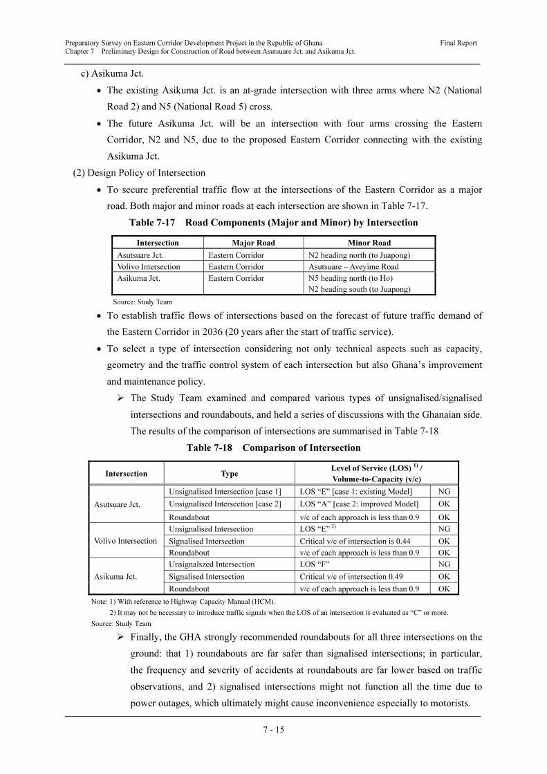
Preparatory Survey on Eastern Corridor Development Project in the Republic of Ghana Final Report
Chapter 7 Preliminary Design for Construction of Road between Asutsuare Jct. and Asikuma Jct.
7 - 15
c) Asikuma Jct.
• The existing Asikuma Jct. is an at-grade intersection with three arms where N2 (National
Road 2) and N5 (National Road 5) cross.
• The future Asikuma Jct. will be an intersection with four arms crossing the Eastern
Corridor, N2 and N5, due to the proposed Eastern Corridor connecting with the existing
Asikuma Jct.
(2) Design Policy of Intersection
• To secure preferential traffic flow at the intersections of the Eastern Corridor as a major
road. Both major and minor roads at each intersection are shown in Table 7-17.
Table 7-17 Road Components (Major and Minor) by Intersection
Intersection Major Road Minor Road
Asutsuare Jct. Eastern Corridor N2 heading north (to Juapong)
Volivo Intersection Eastern Corridor Asutsuare – Aveyime Road
Asikuma Jct. Eastern Corridor N5 heading north (to Ho)
N2 heading south (to Juapong)
Source: Study Team
• To establish traffic flows of intersections based on the forecast of future traffic demand of
the Eastern Corridor in 2036 (20 years after the start of traffic service).
• To select a type of intersection considering not only technical aspects such as capacity,
geometry and the traffic control system of each intersection but also Ghana’s improvement
and maintenance policy.
� The Study Team examined and compared various types of unsignalised/signalised
intersections and roundabouts, and held a series of discussions with the Ghanaian side.
The results of the comparison of intersections are summarised in Table 7-18
Table 7-18 Comparison of Intersection
Intersection Type Level of Service (LOS)
1) /
Volume-to-Capacity (v/c)
Asutsuare Jct.
Unsignalised Intersection [case 1] LOS “E” [case 1: existing Model] NG
Unsignalised Intersection [case 2] LOS “A” [case 2: improved Model] OK
Roundabout v/c of each approach is less than 0.9 OK
Volivo Intersection
Unsignalised Intersection LOS “E” 2) NG
Signalised Intersection Critical v/c of intersection is 0.44 OK
Roundabout v/c of each approach is less than 0.9 OK
Asikuma Jct.
Unsignalszed Intersection LOS “F” NG
Signalised Intersection Critical v/c of intersection 0.49 OK
Roundabout v/c of each approach is less than 0.9 OK
Note: 1) With reference to Highway Capacity Manual (HCM).
2) It may not be necessary to introduce traffic signals when the LOS of an intersection is evaluated as “C” or more.
Source: Study Team
� Finally, the GHA strongly recommended roundabouts for all three intersections on the
ground: that 1) roundabouts are far safer than signalised intersections; in particular,
the frequency and severity of accidents at roundabouts are far lower based on traffic
observations, and 2) signalised intersections might not function all the time due to
power outages, which ultimately might cause inconvenience especially to motorists.
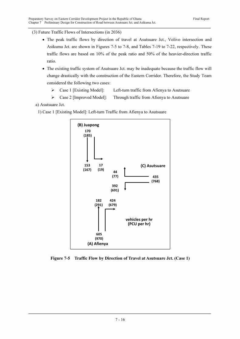
Preparatory Survey on Eastern Corridor Development Project in the Republic of Ghana Final Report
Chapter 7 Preliminary Design for Construction of Road between Asutsuare Jct. and Asikuma Jct.
7 - 16
(3) Future Traffic Flows of Intersections (in 2036)
• The peak traffic flows by direction of travel at Asutsuare Jct., Volivo intersection and
Asikuma Jct. are shown in Figures 7-5 to 7-8, and Tables 7-19 to 7-22, respectively. These
traffic flows are based on 10% of the peak ratio and 50% of the heavier-direction traffic
ratio.
• The existing traffic system of Asutsuare Jct. may be inadequate because the traffic flow will
change drastically with the construction of the Eastern Corridor. Therefore, the Study Team
considered the following two cases:
� Case 1 [Existing Model]: Left-turn traffic from Afienya to Asutsuare
� Case 2 [Improved Model]: Through traffic from Afienya to Asutsuare
a) Asutsuare Jct.
1) Case 1 [Existing Model]: Left-turn Traffic from Afienya to Asutsuare
Figure 7-5 Traffic Flow by Direction of Travel at Asutsuare Jct. (Case 1)
(B) Juapong
(C) Asutsuare
(A) Afienya
44
(77)
392
(691)
435
(768)
153
(167)
17
(19)
170
(185)
vehicles per hr(PCU per hr)
424
(679)
182
(291)
605
(970)

Preparatory Survey on Eastern Corridor Development Project in the Republic of Ghana Final Report
Chapter 7 Preliminary Design for Construction of Road between Asutsuare Jct. and Asikuma Jct.
7 - 17
Table 7-19 Traffic Flow by Direction of Travel at Asutsuare Jct. (Case 1)
Approach Vehicles/hr Commercial
Vehicle RatioDirection Ratio Vehicles/hr PCU/hr
(A) Afienya 605 31.8%
Left - - -
Through 30% 182 291
Right 70% 424 679
(B) Juapong 170 4.7%
Left 10% 17 19
Through 90% 153 167
Right - -
(C) Asutsuare 435 40.3%
Left 90% 392 691
Through 10% 44 77
Right - -
Source: Study Team
2) Case 2 [Improved Model]: Through Traffic from Afienya to Asutsuare
Figure 7-6 Traffic Flow by Direction of Travel at Asutsuare Jct. (Case 2)
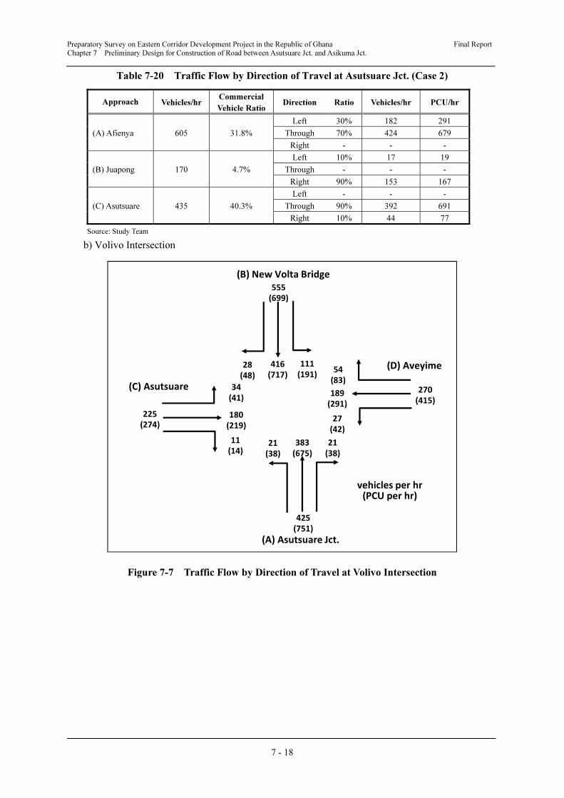
Preparatory Survey on Eastern Corridor Development Project in the Republic of Ghana Final Report
Chapter 7 Preliminary Design for Construction of Road between Asutsuare Jct. and Asikuma Jct.
7 - 18
Table 7-20 Traffic Flow by Direction of Travel at Asutsuare Jct. (Case 2)
Approach Vehicles/hr Commercial
Vehicle RatioDirection Ratio Vehicles/hr PCU/hr
(A) Afienya 605 31.8%
Left 30% 182 291
Through 70% 424 679
Right - - -
(B) Juapong 170 4.7%
Left 10% 17 19
Through - - -
Right 90% 153 167
(C) Asutsuare 435 40.3%
Left - - -
Through 90% 392 691
Right 10% 44 77
Source: Study Team
b) Volivo Intersection
Figure 7-7 Traffic Flow by Direction of Travel at Volivo Intersection
(B) New Volta Bridge
(D) Aveyime
(A) Asutsuare Jct.
(C) Asutsuare
54
(83)
189
(291)
27
(42)
270
(415)
28
(48)
416
(717)
111
(191)
555
(699)
11
(14)
180
(219)
34
(41)
225
(274)
vehicles per hr(PCU per hr)
21
(38)
383
(675)
21
(38)
425
(751)
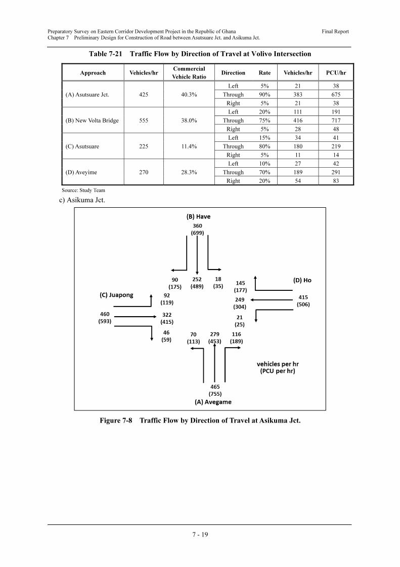
Preparatory Survey on Eastern Corridor Development Project in the Republic of Ghana Final Report
Chapter 7 Preliminary Design for Construction of Road between Asutsuare Jct. and Asikuma Jct.
7 - 19
Table 7-21 Traffic Flow by Direction of Travel at Volivo Intersection
Approach Vehicles/hr Commercial
Vehicle Ratio Direction Rate Vehicles/hr PCU/hr
(A) Asutsuare Jct. 425 40.3%
Left 5% 21 38
Through 90% 383 675
Right 5% 21 38
(B) New Volta Bridge 555 38.0%
Left 20% 111 191
Through 75% 416 717
Right 5% 28 48
(C) Asutsuare 225 11.4%
Left 15% 34 41
Through 80% 180 219
Right 5% 11 14
(D) Aveyime 270 28.3%
Left 10% 27 42
Through 70% 189 291
Right 20% 54 83
Source: Study Team
c) Asikuma Jct.
Figure 7-8 Traffic Flow by Direction of Travel at Asikuma Jct.
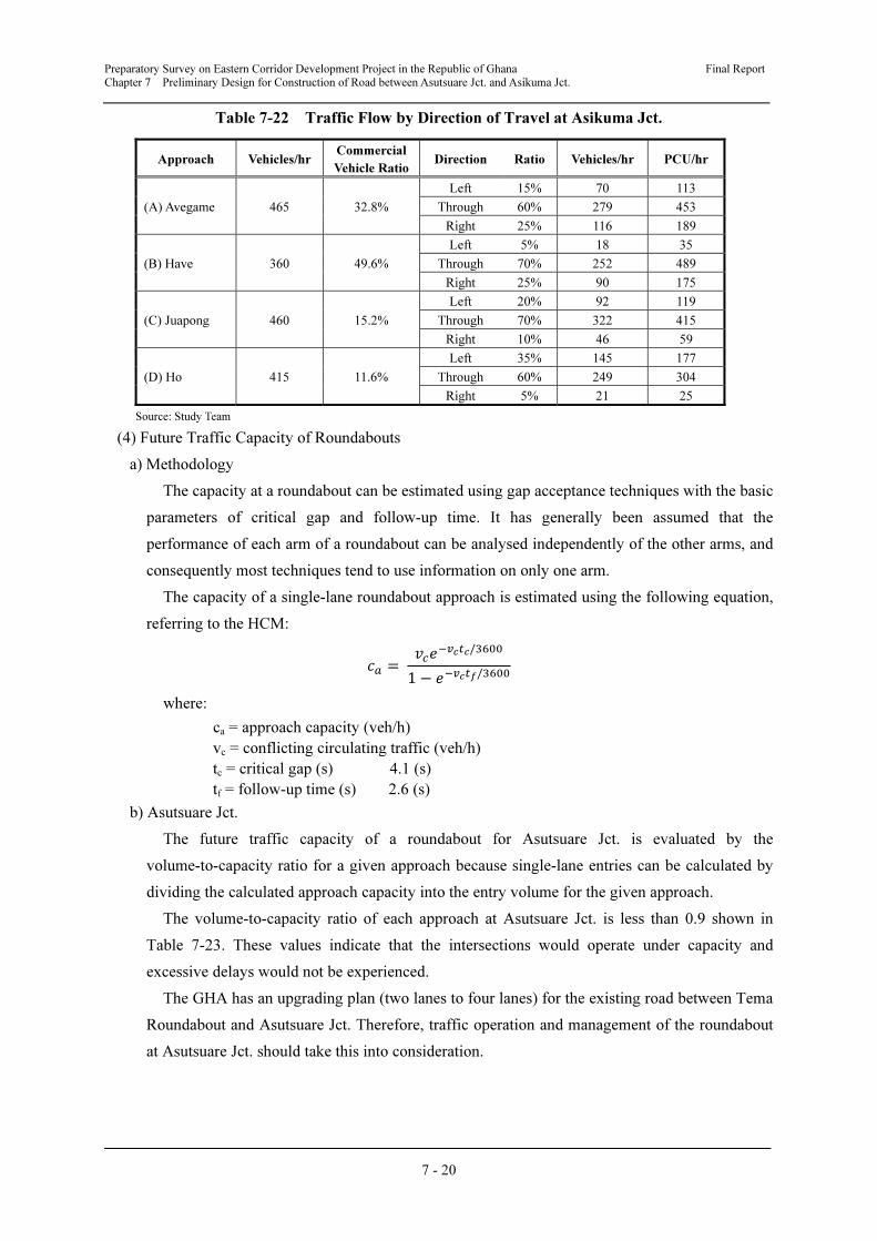
Preparatory Survey on Eastern Corridor Development Project in the Republic of Ghana Final Report
Chapter 7 Preliminary Design for Construction of Road between Asutsuare Jct. and Asikuma Jct.
7 - 20
Table 7-22 Traffic Flow by Direction of Travel at Asikuma Jct.
Approach Vehicles/hr Commercial
Vehicle RatioDirection Ratio Vehicles/hr PCU/hr
(A) Avegame 465 32.8%
Left 15% 70 113
Through 60% 279 453
Right 25% 116 189
(B) Have 360 49.6%
Left 5% 18 35
Through 70% 252 489
Right 25% 90 175
(C) Juapong 460 15.2%
Left 20% 92 119
Through 70% 322 415
Right 10% 46 59
(D) Ho 415 11.6%
Left 35% 145 177
Through 60% 249 304
Right 5% 21 25
Source: Study Team
(4) Future Traffic Capacity of Roundabouts
a) Methodology
The capacity at a roundabout can be estimated using gap acceptance techniques with the basic
parameters of critical gap and follow-up time. It has generally been assumed that the
performance of each arm of a roundabout can be analysed independently of the other arms, and
consequently most techniques tend to use information on only one arm.
The capacity of a single-lane roundabout approach is estimated using the following equation,
referring to the HCM:
� = ���
���/����
1 − ����/����
where:
ca = approach capacity (veh/h)
vc = conflicting circulating traffic (veh/h)
tc = critical gap (s) 4.1 (s)
tf = follow-up time (s) 2.6 (s)
b) Asutsuare Jct.
The future traffic capacity of a roundabout for Asutsuare Jct. is evaluated by the
volume-to-capacity ratio for a given approach because single-lane entries can be calculated by
dividing the calculated approach capacity into the entry volume for the given approach.
The volume-to-capacity ratio of each approach at Asutsuare Jct. is less than 0.9 shown in
Table 7-23. These values indicate that the intersections would operate under capacity and
excessive delays would not be experienced.
The GHA has an upgrading plan (two lanes to four lanes) for the existing road between Tema
Roundabout and Asutsuare Jct. Therefore, traffic operation and management of the roundabout
at Asutsuare Jct. should take this into consideration.
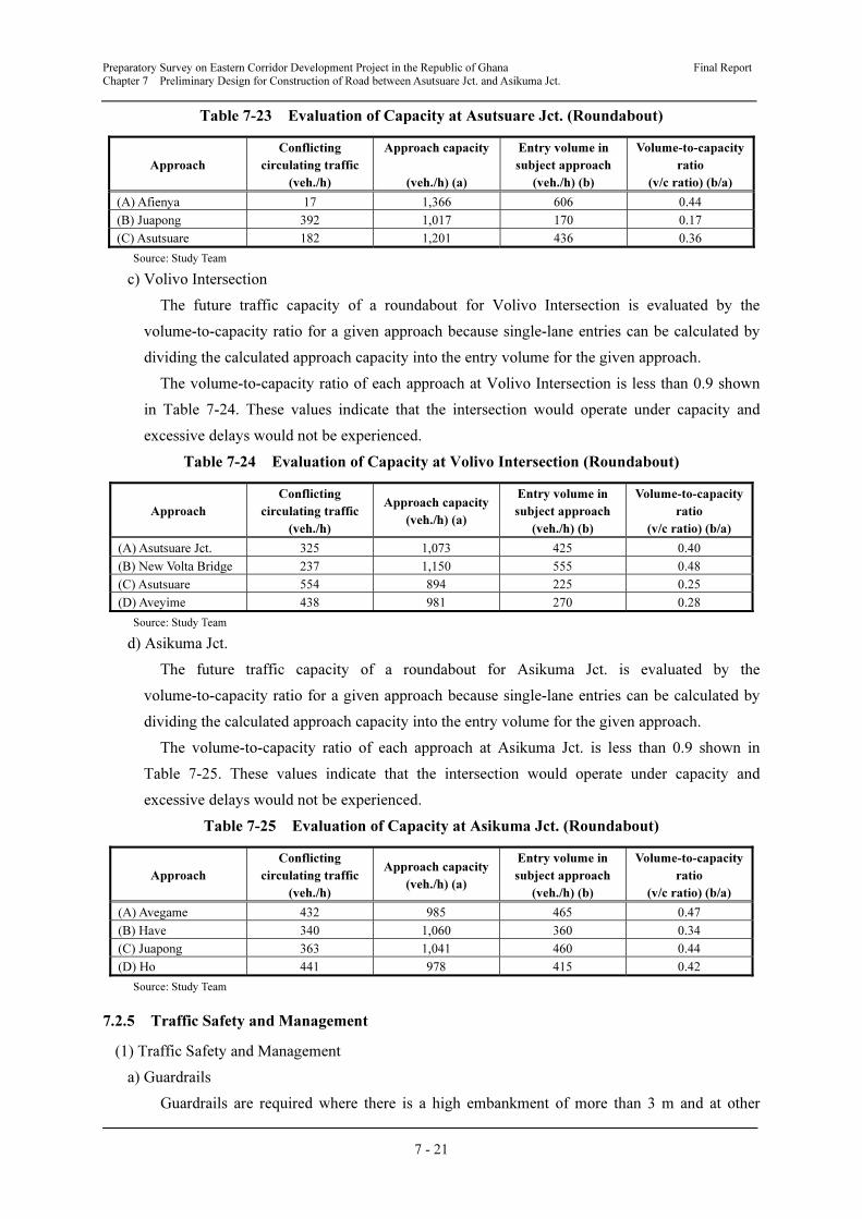
Preparatory Survey on Eastern Corridor Development Project in the Republic of Ghana Final Report
Chapter 7 Preliminary Design for Construction of Road between Asutsuare Jct. and Asikuma Jct.
7 - 21
Table 7-23 Evaluation of Capacity at Asutsuare Jct. (Roundabout)
Approach
Conflicting
circulating traffic
(veh./h)
Approach capacity
(veh./h) (a)
Entry volume in
subject approach
(veh./h) (b)
Volume-to-capacity
ratio
(v/c ratio) (b/a)
(A) Afienya 17 1,366 606 0.44
(B) Juapong 392 1,017 170 0.17
(C) Asutsuare 182 1,201 436 0.36
Source: Study Team
c) Volivo Intersection
The future traffic capacity of a roundabout for Volivo Intersection is evaluated by the
volume-to-capacity ratio for a given approach because single-lane entries can be calculated by
dividing the calculated approach capacity into the entry volume for the given approach.
The volume-to-capacity ratio of each approach at Volivo Intersection is less than 0.9 shown
in Table 7-24. These values indicate that the intersection would operate under capacity and
excessive delays would not be experienced.
Table 7-24 Evaluation of Capacity at Volivo Intersection (Roundabout)
Approach
Conflicting
circulating traffic
(veh./h)
Approach capacity
(veh./h) (a)
Entry volume in
subject approach
(veh./h) (b)
Volume-to-capacity
ratio
(v/c ratio) (b/a)
(A) Asutsuare Jct. 325 1,073 425 0.40
(B) New Volta Bridge 237 1,150 555 0.48
(C) Asutsuare 554 894 225 0.25
(D) Aveyime 438 981 270 0.28
Source: Study Team
d) Asikuma Jct.
The future traffic capacity of a roundabout for Asikuma Jct. is evaluated by the
volume-to-capacity ratio for a given approach because single-lane entries can be calculated by
dividing the calculated approach capacity into the entry volume for the given approach.
The volume-to-capacity ratio of each approach at Asikuma Jct. is less than 0.9 shown in
Table 7-25. These values indicate that the intersection would operate under capacity and
excessive delays would not be experienced.
Table 7-25 Evaluation of Capacity at Asikuma Jct. (Roundabout)
Approach
Conflicting
circulating traffic
(veh./h)
Approach capacity
(veh./h) (a)
Entry volume in
subject approach
(veh./h) (b)
Volume-to-capacity
ratio
(v/c ratio) (b/a)
(A) Avegame 432 985 465 0.47
(B) Have 340 1,060 360 0.34
(C) Juapong 363 1,041 460 0.44
(D) Ho 441 978 415 0.42
Source: Study Team
7.2.5 Traffic Safety and Management
(1) Traffic Safety and Management
a) Guardrails
Guardrails are required where there is a high embankment of more than 3 m and at other
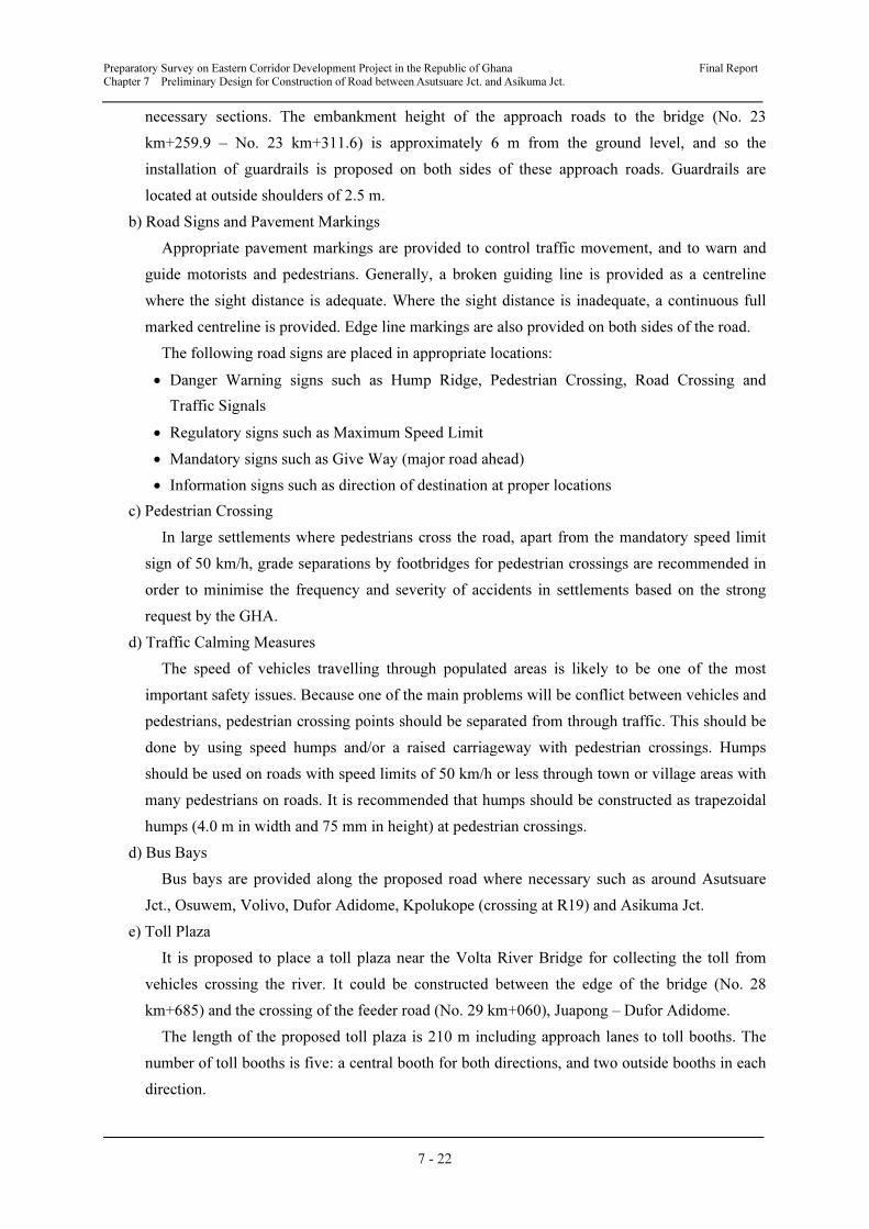
Preparatory Survey on Eastern Corridor Development Project in the Republic of Ghana Final Report
Chapter 7 Preliminary Design for Construction of Road between Asutsuare Jct. and Asikuma Jct.
7 - 22
necessary sections. The embankment height of the approach roads to the bridge (No. 23
km+259.9 – No. 23 km+311.6) is approximately 6 m from the ground level, and so the
installation of guardrails is proposed on both sides of these approach roads. Guardrails are
located at outside shoulders of 2.5 m.
b) Road Signs and Pavement Markings
Appropriate pavement markings are provided to control traffic movement, and to warn and
guide motorists and pedestrians. Generally, a broken guiding line is provided as a centreline
where the sight distance is adequate. Where the sight distance is inadequate, a continuous full
marked centreline is provided. Edge line markings are also provided on both sides of the road.
The following road signs are placed in appropriate locations:
• Danger Warning signs such as Hump Ridge, Pedestrian Crossing, Road Crossing and
Traffic Signals
• Regulatory signs such as Maximum Speed Limit
• Mandatory signs such as Give Way (major road ahead)
• Information signs such as direction of destination at proper locations
c) Pedestrian Crossing
In large settlements where pedestrians cross the road, apart from the mandatory speed limit
sign of 50 km/h, grade separations by footbridges for pedestrian crossings are recommended in
order to minimise the frequency and severity of accidents in settlements based on the strong
request by the GHA.
d) Traffic Calming Measures
The speed of vehicles travelling through populated areas is likely to be one of the most
important safety issues. Because one of the main problems will be conflict between vehicles and
pedestrians, pedestrian crossing points should be separated from through traffic. This should be
done by using speed humps and/or a raised carriageway with pedestrian crossings. Humps
should be used on roads with speed limits of 50 km/h or less through town or village areas with
many pedestrians on roads. It is recommended that humps should be constructed as trapezoidal
humps (4.0 m in width and 75 mm in height) at pedestrian crossings.
d) Bus Bays
Bus bays are provided along the proposed road where necessary such as around Asutsuare
Jct., Osuwem, Volivo, Dufor Adidome, Kpolukope (crossing at R19) and Asikuma Jct.
e) Toll Plaza
It is proposed to place a toll plaza near the Volta River Bridge for collecting the toll from
vehicles crossing the river. It could be constructed between the edge of the bridge (No. 28
km+685) and the crossing of the feeder road (No. 29 km+060), Juapong – Dufor Adidome.
The length of the proposed toll plaza is 210 m including approach lanes to toll booths. The
number of toll booths is five: a central booth for both directions, and two outside booths in each
direction.
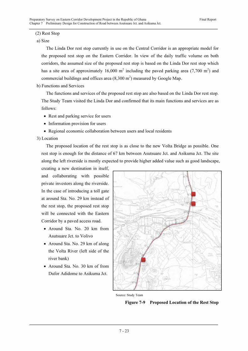
Preparatory Survey on Eastern Corridor Development Project in the Republic of Ghana Final Report
Chapter 7 Preliminary Design for Construction of Road between Asutsuare Jct. and Asikuma Jct.
7 - 23
(2) Rest Stop
a) Size
The Linda Dor rest stop currently in use on the Central Corridor is an appropriate model for
the proposed rest stop on the Eastern Corridor. In view of the daily traffic volume on both
corridors, the assumed size of the proposed rest stop is based on the Linda Dor rest stop which
has a site area of approximately 16,000 m2 including the paved parking area (7,700 m
2) and
commercial buildings and offices area (8,300 m2) measured by Google Map.
b) Functions and Services
The functions and services of the proposed rest stop are also based on the Linda Dor rest stop.
The Study Team visited the Linda Dor and confirmed that its main functions and services are as
follows:
• Rest and parking service for users
• Information provision for users
• Regional economic collaboration between users and local residents
3) Location
The proposed location of the rest stop is as close to the new Volta Bridge as possible. One
rest stop is enough for the distance of 67 km between Asutsuare Jct. and Asikuma Jct. The site
along the left riverside is mostly expected to provide higher added value such as good landscape,
creating a new destination in itself,
and collaborating with possible
private investors along the riverside.
In the case of introducing a toll gate
at around Sta. No. 29 km instead of
the rest stop, the proposed rest stop
will be connected with the Eastern
Corridor by a paved access road.
• Around Sta. No. 20 km from
Asutsuare Jct. to Volivo
• Around Sta. No. 29 km of along
the Volta River (left side of the
river bank)
• Around Sta. No. 30 km of from
Dufor Adidome to Asikuma Jct.
Source: Study Team
Figure 7-9 Proposed Location of the Rest Stop
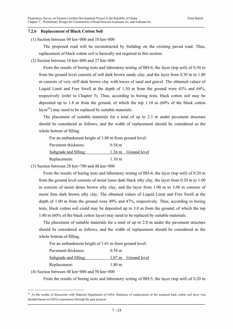
Preparatory Survey on Eastern Corridor Development Project in the Republic of Ghana Final Report
Chapter 7 Preliminary Design for Construction of Road between Asutsuare Jct. and Asikuma Jct.
7 - 24
7.2.6 Replacement of Black Cotton Soil
(1) Section between 00 km+000 and 10 km+800
The proposed road will be reconstructed by building on the existing paved road. Thus,
replacement of black cotton soil is basically not required in this section.
(2) Section between 10 km+800 and 27 km+600
From the results of boring tests and laboratory testing of BH-6, the layer (top soil) of 0.30 m
from the ground level consists of soft dark brown sandy clay, and the layer from 0.30 m to 1.80
m consists of very stiff dark brown clay with traces of sand and gravel. The obtained values of
Liquid Limit and Free Swell at the depth of 1.50 m from the ground were 43% and 64%,
respectively (refer to Chapter 5). Thus, according to boring tests, black cotton soil may be
deposited up to 1.8 m from the ground, of which the top 1.10 m (60% of the black cotton
layer26) may need to be replaced by suitable materials.
The placement of suitable materials for a total of up to 2.3 m under pavement structure
should be considered as follows, and the width of replacement should be considered as the
whole bottom of filling.
For an embankment height of 1.80 m from ground level:
Pavement thickness: 0.54 m
Subgrade and filling: 1.26 m Ground level
Replacement: 1.10 m
(3) Section between 28 km+700 and 48 km+000
From the results of boring tests and laboratory testing of BH-4, the layer (top soil) of 0.20 m
from the ground level consists of moist loose dark black silty clay, the layer from 0.20 m to 1.00
m consists of moist dense brown silty clay, and the layer from 1.00 m to 3.00 m consists of
moist firm dark brown silty clay. The obtained values of Liquid Limit and Free Swell at the
depth of 1.00 m from the ground were 49% and 47%, respectively. Thus, according to boring
tests, black cotton soil could may be deposited up to 3.0 m from the ground, of which the top
1.80 m (60% of the black cotton layer) may need to be replaced by suitable materials.
The placement of suitable materials for a total of up to 2.8 m under the pavement structure
should be considered as follows, and the width of replacement should be considered as the
whole bottom of filling.
For an embankment height of 1.61 m from ground level:
Pavement thickness: 0.54 m
Subgrade and filling: 1.07 m Ground level
Replacement: 1.80 m
(4) Section between 48 km+000 and 50 km+000
From the results of boring tests and laboratory testing of BH-5, the layer (top soil) of 0.20 m
26 As the results of discussion with Material Department of GHA, thickness of replacement of the assumed back cotton soil layer was
decided based on GHA’s experiences through the past projects.
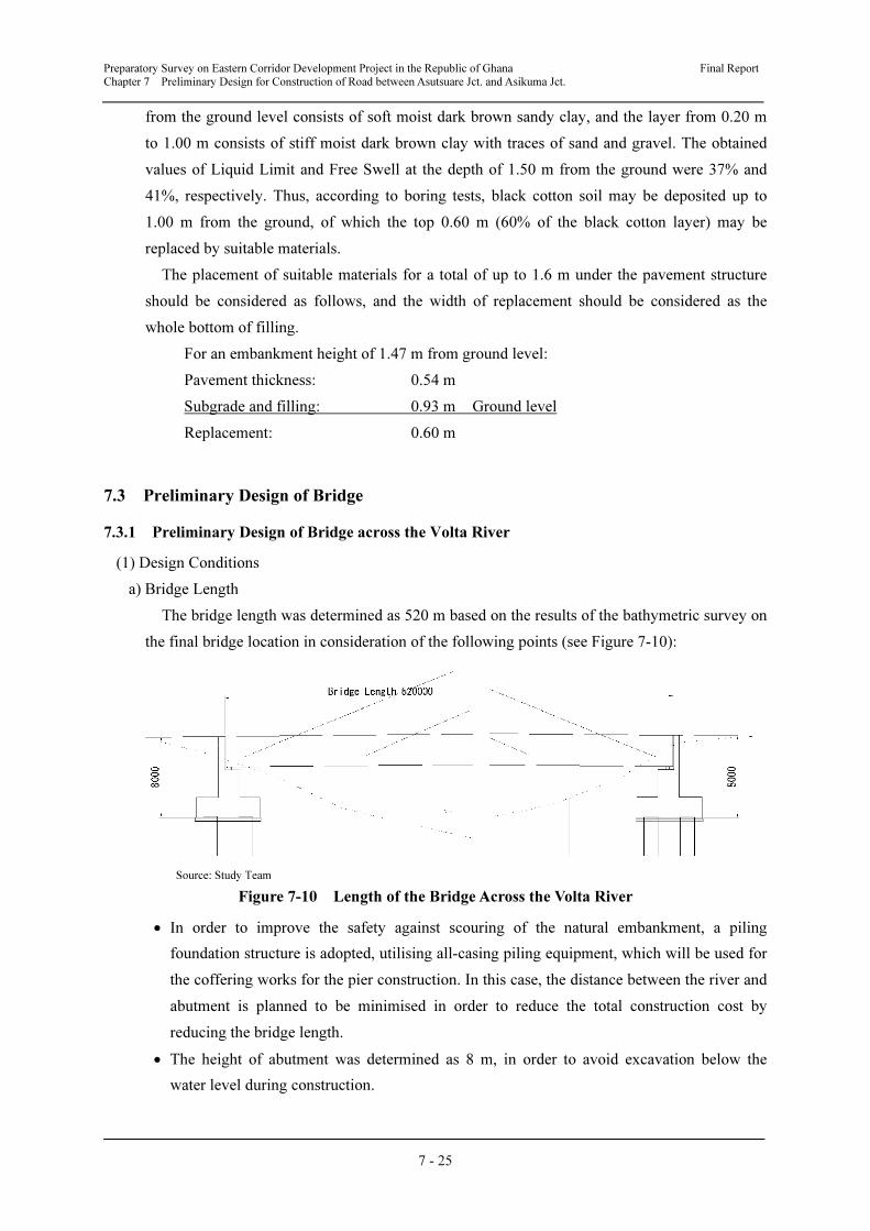
Preparatory Survey on Eastern Corridor Development Project in the Republic of Ghana Final Report
Chapter 7 Preliminary Design for Construction of Road between Asutsuare Jct. and Asikuma Jct.
7 - 25
from the ground level consists of soft moist dark brown sandy clay, and the layer from 0.20 m
to 1.00 m consists of stiff moist dark brown clay with traces of sand and gravel. The obtained
values of Liquid Limit and Free Swell at the depth of 1.50 m from the ground were 37% and
41%, respectively. Thus, according to boring tests, black cotton soil may be deposited up to
1.00 m from the ground, of which the top 0.60 m (60% of the black cotton layer) may be
replaced by suitable materials.
The placement of suitable materials for a total of up to 1.6 m under the pavement structure
should be considered as follows, and the width of replacement should be considered as the
whole bottom of filling.
For an embankment height of 1.47 m from ground level:
Pavement thickness: 0.54 m
Subgrade and filling: 0.93 m Ground level
Replacement: 0.60 m
7.3 Preliminary Design of Bridge
7.3.1 Preliminary Design of Bridge across the Volta River
(1) Design Conditions
a) Bridge Length
The bridge length was determined as 520 m based on the results of the bathymetric survey on
the final bridge location in consideration of the following points (see Figure 7-10):
Source: Study Team
Figure 7-10 Length of the Bridge Across the Volta River
• In order to improve the safety against scouring of the natural embankment, a piling
foundation structure is adopted, utilising all-casing piling equipment, which will be used for
the coffering works for the pier construction. In this case, the distance between the river and
abutment is planned to be minimised in order to reduce the total construction cost by
reducing the bridge length.
• The height of abutment was determined as 8 m, in order to avoid excavation below the
water level during construction.
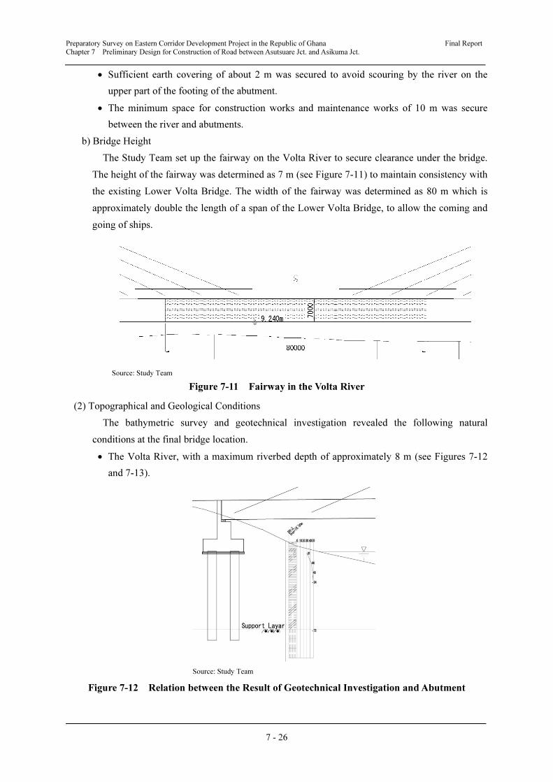
Preparatory Survey on Eastern Corridor Development Project in the Republic of Ghana Final Report
Chapter 7 Preliminary Design for Construction of Road between Asutsuare Jct. and Asikuma Jct.
7 - 26
• Sufficient earth covering of about 2 m was secured to avoid scouring by the river on the
upper part of the footing of the abutment.
• The minimum space for construction works and maintenance works of 10 m was secure
between the river and abutments.
b) Bridge Height
The Study Team set up the fairway on the Volta River to secure clearance under the bridge.
The height of the fairway was determined as 7 m (see Figure 7-11) to maintain consistency with
the existing Lower Volta Bridge. The width of the fairway was determined as 80 m which is
approximately double the length of a span of the Lower Volta Bridge, to allow the coming and
going of ships.
Source: Study Team
Figure 7-11 Fairway in the Volta River
(2) Topographical and Geological Conditions
The bathymetric survey and geotechnical investigation revealed the following natural
conditions at the final bridge location.
• The Volta River, with a maximum riverbed depth of approximately 8 m (see Figures 7-12
and 7-13).
Source: Study Team
Figure 7-12 Relation between the Result of Geotechnical Investigation and Abutment
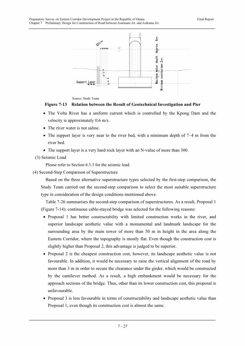
Preparatory Survey on Eastern Corridor Development Project in the Republic of Ghana Final Report
Chapter 7 Preliminary Design for Construction of Road between Asutsuare Jct. and Asikuma Jct.
7 - 27
Source: Study Team
Figure 7-13 Relation between the Result of Geotechnical Investigation and Pier
• The Volta River has a uniform current which is controlled by the Kpong Dam and the
velocity is approximately 0.6 m/s.
• The river water is not saline.
• The support layer is very near to the river bed, with a minimum depth of 7–4 m from the
river bed.
• The support layer is a very hard rock layer with an N-value of more than 300.
(3) Seismic Load
Please refer to Section 6.3.3 for the seismic load.
(4) Second-Step Comparison of Superstructure
Based on the three alternative superstructure types selected by the first-step comparison, the
Study Team carried out the second-step comparison to select the most suitable superstructure
type in consideration of the design conditions mentioned above.
Table 7-26 summarises the second-step comparison of superstructures. As a result, Proposal 1
(Figure 7-14): continuous cable-stayed bridge was selected for the following reasons:
• Proposal 1 has better constructability with limited construction works in the river, and
superior landscape aesthetic value with a monumental and landmark landscape for the
surrounding area by the main tower of more than 50 m in height in the area along the
Eastern Corridor, where the topography is mostly flat. Even though the construction cost is
slightly higher than Proposal 2, this advantage is judged to be superior.
• Proposal 2 is the cheapest construction cost, however, its landscape aesthetic value is not
favourable. In addition, it would be necessary to raise the vertical alignment of the road by
more than 3 m in order to secure the clearance under the girder, which would be constructed
by the cantilever method. As a result, a high embankment would be necessary for the
approach sections of the bridge. Thus, other than its lower construction cost, this proposal is
unfavourable.
• Proposal 3 is less favourable in terms of constructability and landscape aesthetic value than
Proposal 1, even though its construction cost is almost the same.

7 - 28
Table 7-26 Comparison of Bridge Structures over the Volta River (Second-Step)
Side-view Drawing, Main Girder Cross-section, and Concept Image Midpoint bridge
pier cross-section Structural features Constructability
Aesthetic value and impact on surrounding
environment
Cost
performance Judgment
Proposal 1
Continuous
cable-stayed
bridge
Main girders:
steel-floor box
girder
Main towers:
reinforced
concrete
Foundation:
spread footing
(steel pipe sheet
pile cofferdam)
•Large spans exceeding 200
m with a relatively large
number of past examples.
•There is no problem in the
fatigue durability of the steel
floor plate, as highly-durable
steel floor plate that has
passed a two-million cycle
fatigue test is planned.
•Using a box-girder structure
with high torsional rigidity as
a base, sufficient wind
resistance is possible if
wind-tunnel testing is
conducted.
(Good)
•Since many parts
can be fabricated in
highly-controlled
factories, the quality
can be secured.
•With the least
volume of in-river
work, the safety and
precision of
construction can be
secured.
(Very Good)
•The main towers and
cables have a
monumental presence to
effectively function as
an area landmark.
•The balance between
the scale of the bridge
(length/width, etc.), the
height of the towers,
and the number of
cables is good, giving it
aesthetically pleasing
proportions.
(Very Good)
Ratio: 1.06
(Good)
Very Good
Proposal 2
Precast
Concrete
Box-girder
Bridge
(cantilever
method)
Main girders:
concrete
Piers:
reinforced
concrete
(rubber bearing
support)
Foundation:
spread footing
(steel pipe sheet
pile cofferdam)
•Spans of approximately 100
m with a very large number of
past examples.
•Piers are short compared to
the length of the bridge,
making thermal stress relief
difficult. Therefore, a reaction
force dispersion structure
using rubber bearings must be
used. (Due to this, this
structure type does not have
sufficient cost advantages.)
(Good)
•Since many parts are
constructed at the
site, quality control is
not easy.
• Since there are
many in-river works,
the safety and
precision of
construction are
lower.
(Fair)
• The unique rhythmical
appearance of a
non-uniform cross
section is an
aesthetically pleasing
type of structure.
However, for this
bridge, there are almost
no vantage points
offering this view,
giving it less
landscaping value.
•The increased beam
height makes the bridge
4 m higher than the
road, which worsens the
approach to the road at
the ends of the bridge.
(Fair)
Ratio: 1.00
(Very Good)
Fair
Proposal 3
Precast
Concrete
Extradosed
Bridge
Main girders:
concrete
Piers: RC piers
(rubber bearing
support)
Foundation:
spread footing
(steel pipe sheet
pile cofferdam)
•Bridges with 150-250 m
spans have rapidly increased
in recent years.
•Bridge piers are short
compared to the length of the
bridge, making thermal stress
relief difficult. Therefore, a
reaction force dispersion
structure using rubber
bearings must be used. (Due
to this, this structure type
does not have sufficient cost
advantages.)
(Good)
•Since many parts are
constructed at the
site, quality control is
not easy.
• Since there are
many in-river works,
the safety and
precision of
construction are
lower.
(Fair)
•The towers and cables
on the bridge surface
give a monumental
presence, but with its
small scale, it lacks
effectiveness as a
landmark.
•Towers are short
compared to the bridge
width, giving it poor
aesthetic balance.
(Good)
Ratio: 1.07
(Good)
Good
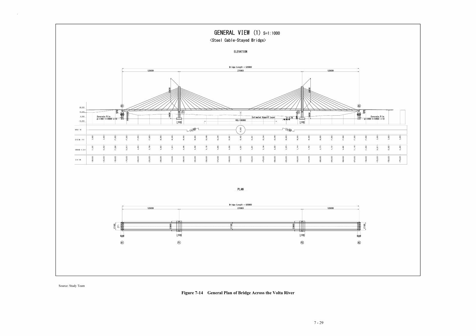
.
7 - 29
Source: Study Team
Figure 7-14 General Plan of Bridge Across the Volta River
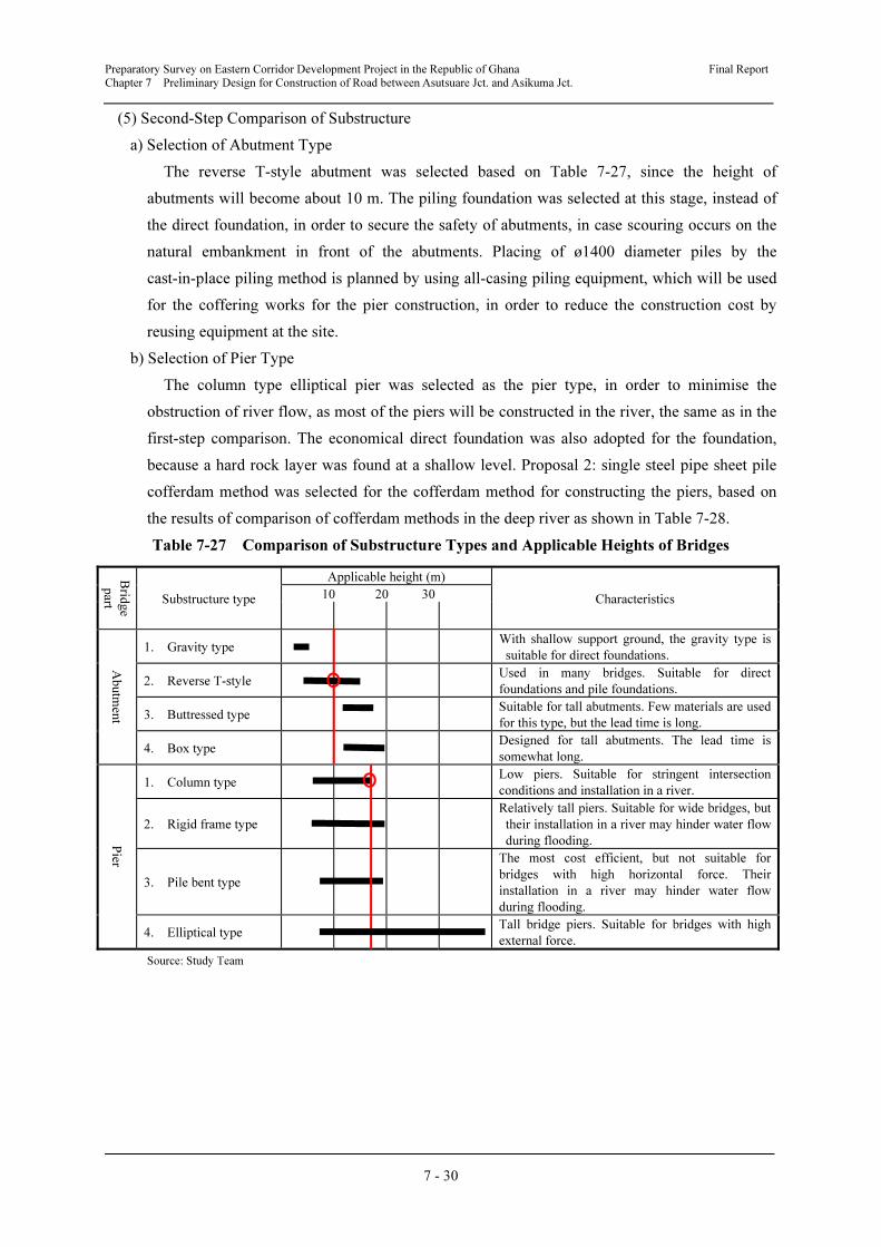
Preparatory Survey on Eastern Corridor Development Project in the Republic of Ghana Final Report
Chapter 7 Preliminary Design for Construction of Road between Asutsuare Jct. and Asikuma Jct.
7 - 30
(5) Second-Step Comparison of Substructure
a) Selection of Abutment Type
The reverse T-style abutment was selected based on Table 7-27, since the height of
abutments will become about 10 m. The piling foundation was selected at this stage, instead of
the direct foundation, in order to secure the safety of abutments, in case scouring occurs on the
natural embankment in front of the abutments. Placing of ø1400 diameter piles by the
cast-in-place piling method is planned by using all-casing piling equipment, which will be used
for the coffering works for the pier construction, in order to reduce the construction cost by
reusing equipment at the site.
b) Selection of Pier Type
The column type elliptical pier was selected as the pier type, in order to minimise the
obstruction of river flow, as most of the piers will be constructed in the river, the same as in the
first-step comparison. The economical direct foundation was also adopted for the foundation,
because a hard rock layer was found at a shallow level. Proposal 2: single steel pipe sheet pile
cofferdam method was selected for the cofferdam method for constructing the piers, based on
the results of comparison of cofferdam methods in the deep river as shown in Table 7-28.
Table 7-27 Comparison of Substructure Types and Applicable Heights of Bridges
Brid
ge
part Substructure type
Applicable height (m)
Characteristics 10 20 30
Abutm
ent
1. Gravity type With shallow support ground, the gravity type is
suitable for direct foundations.
2. Reverse T-style Used in many bridges. Suitable for direct
foundations and pile foundations.
3. Buttressed type Suitable for tall abutments. Few materials are used
for this type, but the lead time is long.
4. Box type Designed for tall abutments. The lead time is
somewhat long. P
ier
1. Column type Low piers. Suitable for stringent intersection
conditions and installation in a river.
2. Rigid frame type
Relatively tall piers. Suitable for wide bridges, but
their installation in a river may hinder water flow
during flooding.
3. Pile bent type
The most cost efficient, but not suitable for
bridges with high horizontal force. Their
installation in a river may hinder water flow
during flooding.
4. Elliptical type Tall bridge piers. Suitable for bridges with high
external force.
Source: Study Team

Preparatory Survey on Eastern Corridor Development Project in the Republic of Ghana Final Report
Chapter 7 Preliminary Design for Construction of Road between Asutsuare Jct. and Asikuma Jct.
7 - 31
Table 7-28 Comparison of Cofferdam Methods for Pier Construction
Item Proposal 1
Double Sheet Pile Cofferdam
Proposal 2
Single Steel Pipe Sheet Pile Cofferdam
Cross Section
Outline of
Structure
The capability of preventing water leaks and
stability is improved, by placing two double sheet
piles with soil/sand placed in between. Sheet piles
are fixed by tie-rods. Special rock excavation
equipment, such as a Down Hole Hammer, is
required for penetrating the sheet piles into the
rock layer.
A high capability of
preventing water
leaks is secured by
steel pipes with
high stiffness and
joints between pipes, as shown below. Large scale
rock excavation equipment, such as all casing
piling equipment, is required for penetrating the
steel piles into the rock layer.
Constructability
Excavation of rock layer with ø500 diameter under
the water level by wrapping sheet piles is
considered to be technically difficult. In addition,
placing and removing of soil/sand between sheet
piles are also complicated works. (Fair)
Excavation of rock layer with ø1400 diameter
under the water level by wrapping steel pipes is
easier, because the tolerance is larger. Also, works
to prevent water leaks are easier.
(Good)
Construction
Cost
Ratio: 1.13
(Fair)
Ratio: 1.00
(Good)
Judgment Fair Good
Source: Study Team
7.3.2 Preliminary Design of Bridge across the Alabo River
(1) Design Condition
a) Bridge Placing Plan
• The Study Team adopted the H.W.L. of 67.155 m, which was used for the design of the
M11 Bridge, located about 300 m downstream of the planned bridge location, in the
“Construction of Medium and Small Scale Bridges in the Republic of Ghana” under the
donation programme of the Government of Japan.
• The bridge length should be longer than the M11 Bridge (46.940m).
b) Geotechnical Conditions
• According to the results of geotechnical investigation near the planned bridge site, a clay
layer with an N-value of more than 50 (see Figure 7-15) was found at about GL-5 m and a
rock layer was found at GL-6 m. Since the river channel has often changed, the foundation
should be placed on a stable layer. Thus, the rock layer from GL-6 m was considered as the
bearing layer of the substructure.

Preparatory Survey on Eastern Corridor Development Project in the Republic of Ghana Final Report
Chapter 7 Preliminary Design for Construction of Road between Asutsuare Jct. and Asikuma Jct.
7 - 32
Source: Study Team
Figure 7-15 Relation between Result of Geotechnical Investigation, and Location of Abutments
and Pier
(2) Bridge Planning
The bridge length was determined as 50 m = 2@25 m, considering the length of more than
46.940 m shown in Figure 7-16, as well as to be the same length as the Bridge across the
planned APGIP Main Canal, described below, in order to reduce the cost by reusing materials
such as formworks.
(3) Selection of Superstructure Type
The continuous T-girder type was selected based on Table 7-29 for the following reasons:
• The continuous girder type was mainly compared because of its seismic resistance.
• Concrete bridges require less maintenance and are economical.
• The continuous composite girder type has problems such as difficulty of construction and
quality control
• This type of bridges is commonly used in Ghana.
(4) Selection of Substructure Type
a) Selection of Abutment Type
The reverse T-style abutment was selected based on Table 7-27, since the height of the
abutment will be 10 m. The economical direct foundation was selected for the foundation type,
as a rock layer with an N-Value of more than exists at the bottom of planned footings.
b) Selection of Pier Type
The column type elliptical pier was selected as the pier type, in order to minimise obstruction
of river flow, as the piers will be constructed in the river. The economical direct foundation was
adopted for the foundation, because a hard rock layer was found at a very shallow level.
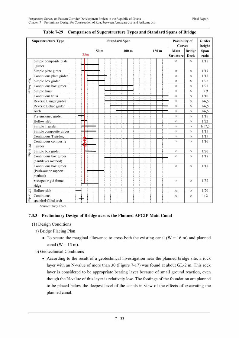
Preparatory Survey on Eastern Corridor Development Project in the Republic of Ghana Final Report
Chapter 7 Preliminary Design for Construction of Road between Asutsuare Jct. and Asikuma Jct.
7 - 33
Table 7-29 Comparison of Superstructure Types and Standard Spans of Bridge
Superstructure Type Standard Span Possibility of
Curves
Girder
height
50 m 100 m 150 m Main
Structure
Bridge
Deck
Span
ratio
Steel b
ridg
e
Simple composite plate
girder
○ ○ 1/18
Simple plate girder ○ ○ 1/17
Continuous plate girder ○ ○ 1/18
Simple box girder ○ ○ 1/22
Continuous box girder ○ ○ 1/23
Simple truss × ○ 1/ 9
Continuous truss × ○ 1/10
Reverse Langer girder × ○ 1/6,5
Reverse Lohse girder × ○ 1/6,5
Arch × ○ 1/6,5
PC
brid
ge
Pretensioned girder × ○ 1/15
Hollow slab ○ ○ 1/22
Simple T girder × ○ 1/17,5
Simple composite girder × ○ 1/15
Continuous T girder, × ○ 1/15
Continuous composite
girder
× ○ 1/16
Simple box girder ○ ○ 1/20
Continuous box girder
(cantilever method)
○ ○ 1/18
Continuous box girder
(Push-out or support
method)
○ ○ 1/18
π shaped rigid frame
ridge
× ○ 1/32
RC
brid
ge
Hollow slab ○ ○ 1/20
Continuous
spandrel-filled arch
○ ○ 1/ 2
Source: Study Team
7.3.3 Preliminary Design of Bridge across the Planned APGIP Main Canal
(1) Design Conditions
a) Bridge Placing Plan
• To secure the marginal allowance to cross both the existing canal (W = 16 m) and planned
canal (W = 15 m).
b) Geotechnical Conditions
• According to the result of a geotechnical investigation near the planned bridge site, a rock
layer with an N-value of more than 30 (Figure 7-17) was found at about GL-2 m. This rock
layer is considered to be appropriate bearing layer because of small ground reaction, even
though the N-value of this layer is relatively low. The footings of the foundation are planned
to be placed below the deepest level of the canals in view of the effects of excavating the
planned canal.
25m
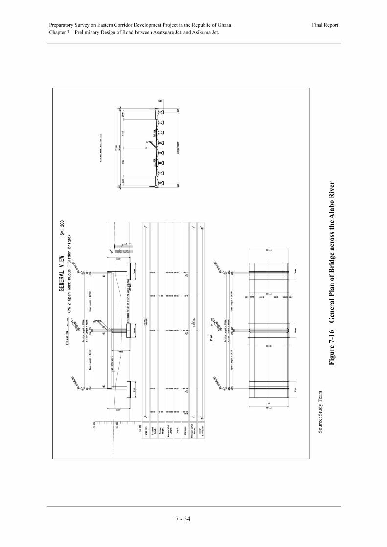
Preparatory Survey on Eastern Corridor Development Project in the Republic of Ghana
Final Report
Chapter 7 Preliminary Design of Road between Asutsuare Jct. and Asikuma Jct.
7 - 34
S
ou
rce:
Stu
dy
Tea
m
Fig
ure
7-1
6 G
enera
l P
lan
of
Bri
dg
e a
cro
ss t
he
Ala
bo
Riv
er
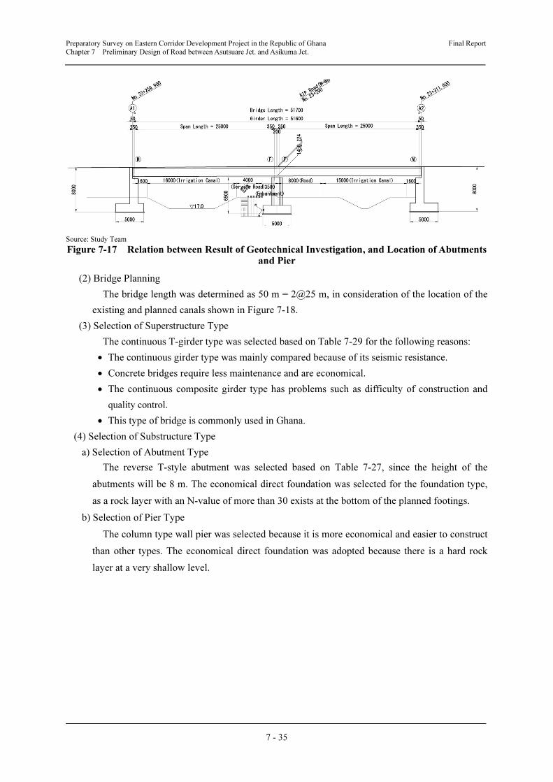
Preparatory Survey on Eastern Corridor Development Project in the Republic of Ghana Final Report
Chapter 7 Preliminary Design of Road between Asutsuare Jct. and Asikuma Jct.
7 - 35
Source: Study Team
Figure 7-17 Relation between Result of Geotechnical Investigation, and Location of Abutments and Pier
(2) Bridge Planning
The bridge length was determined as 50 m = 2@25 m, in consideration of the location of the
existing and planned canals shown in Figure 7-18.
(3) Selection of Superstructure Type
The continuous T-girder type was selected based on Table 7-29 for the following reasons:
• The continuous girder type was mainly compared because of its seismic resistance.
• Concrete bridges require less maintenance and are economical.
• The continuous composite girder type has problems such as difficulty of construction and
quality control.
• This type of bridge is commonly used in Ghana.
(4) Selection of Substructure Type
a) Selection of Abutment Type
The reverse T-style abutment was selected based on Table 7-27, since the height of the
abutments will be 8 m. The economical direct foundation was selected for the foundation type,
as a rock layer with an N-value of more than 30 exists at the bottom of the planned footings.
b) Selection of Pier Type
The column type wall pier was selected because it is more economical and easier to construct
than other types. The economical direct foundation was adopted because there is a hard rock
layer at a very shallow level.
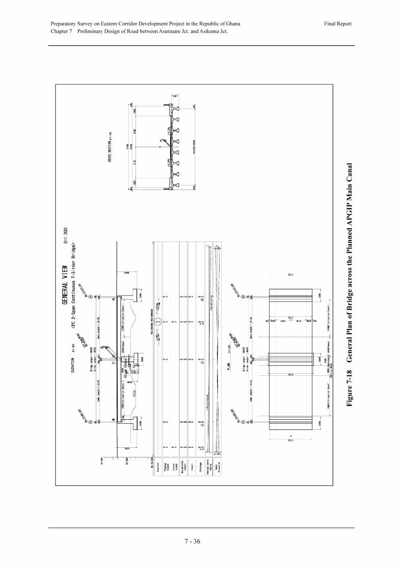
Preparatory Survey on Eastern Corridor Development Project in the Republic of Ghana
Final Report
Chapter 7 Preliminary Design of Road between Asutsuare Jct. and Asikuma Jct.
7 - 36
Fig
ure
7-1
8 G
enera
l P
lan
of
Bri
dg
e a
cro
ss t
he
Pla
nn
ed A
PG
IP M
ain
Ca
na
l
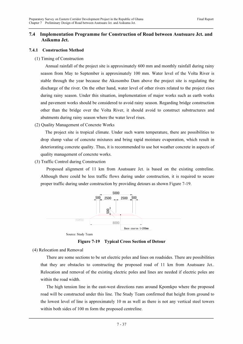
Preparatory Survey on Eastern Corridor Development Project in the Republic of Ghana Final Report
Chapter 7 Preliminary Design of Road between Asutsuare Jct. and Asikuma Jct.
7 - 37
7.4 Implementation Programme for Construction of Road between Asutsuare Jct. and
Asikuma Jct.
7.4.1 Construction Method
(1) Timing of Construction
Annual rainfall of the project site is approximately 600 mm and monthly rainfall during rainy
season from May to September is approximately 100 mm. Water level of the Volta River is
stable through the year because the Akosombo Dam above the project site is regulating the
discharge of the river. On the other hand, water level of other rivers related to the project rises
during rainy season. Under this situation, implementation of major works such as earth works
and pavement works should be considered to avoid rainy season. Regarding bridge construction
other than the bridge over the Volta River, it should avoid to construct substructures and
abutments during rainy season where the water level rises.
(2) Quality Management of Concrete Works
The project site is tropical climate. Under such warm temperature, there are possibilities to
drop slump value of concrete mixtures and bring rapid moisture evaporation, which result in
deteriorating concrete quality. Thus, it is recommended to use hot weather concrete in aspects of
quality management of concrete works.
(3) Traffic Control during Construction
Proposed alignment of 11 km from Asutsuare Jct. is based on the existing centreline.
Although there could be less traffic flows during under construction, it is required to secure
proper traffic during under construction by providing detours as shown Figure 7-19.
Source: Study Team
Figure 7-19 Typical Cross Section of Detour
(4) Relocation and Removal
There are some sections to be set electric poles and lines on roadsides. There are possibilities
that they are obstacles to constructing the proposed road of 11 km from Asutsuare Jct..
Relocation and removal of the existing electric poles and lines are needed if electric poles are
within the road width.
The high tension line in the east-west directions runs around Kpomkpo where the proposed
road will be constructed under this line. The Study Team confirmed that height from ground to
the lowest level of line is approximately 10 m as well as there is not any vertical steel towers
within both sides of 100 m form the proposed centreline.
2500 5002500500
5000
500
Base course t=200mm
8000

Preparatory Survey on Eastern Corridor Development Project in the Republic of Ghana Final Report
Chapter 7 Preliminary Design of Road between Asutsuare Jct. and Asikuma Jct.
7 - 38
7.4.2 Material and Equipment Procurement
(1) Construction Material Procurement
The situations of major construction procurement in Ghana are as follows.
• Since quarry sites for procurement of aggregate are dotted around the project site, aggregate
could be available relatively easily. However, it should be examined procurement in detailed
at the construction stage considering stable supply qualitatively and quantitatively.
• There are some cement production companies in Ghana. It should be examined procurement
in detailed at the construction stage considering stable supply qualitatively and
quantitatively.
• Bitumen materials will be procured from foreign countries because local procurement is not
possible for the entire amount.
• Bridge construction materials such as PC steel materials, steel pipes, cables, bearing and
expansion devices will be procured from foreign countries because local procurement is not
possible completely.
• It is desirable that filling materials will be procured from near the project site for
workability and economic reasons. The Study Team carried out surveys for two borrow pits
located as shown in Figure 7-20 and results of survey are shown in Table 7-30.
(2) Procurement of Construction Equipment
• General construction equipment such as backhoe and 50 ton crane are available for local
procurement. However, equipment such as crane more than 100 tonne and benoto boring
equipment will be procured form foreign countries because local procurement is not
possible completely.
Source: Study Team
Figure 7-20 Location of Borrow Pits Sites
No.1
No.2
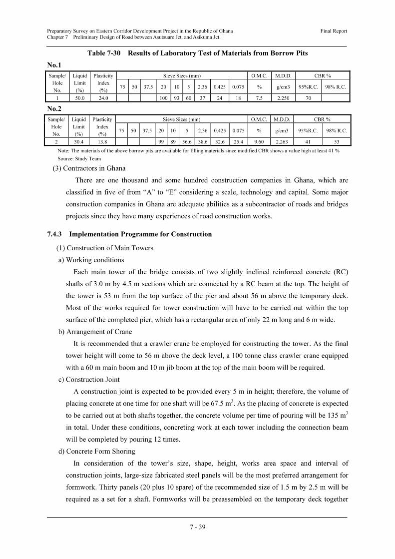
Preparatory Survey on Eastern Corridor Development Project in the Republic of Ghana Final Report
Chapter 7 Preliminary Design of Road between Asutsuare Jct. and Asikuma Jct.
7 - 39
Table 7-30 Results of Laboratory Test of Materials from Borrow Pits
No.1
Sample/
Hole
No.
Liquid
Limit
(%)
Plasticity
Index
(%)
Sieve Sizes (mm) O.M.C. M.D.D. CBR %
75 50 37.5 20 10 5 2.36 0.425 0.075 % g/cm3 95%R.C. 98% R.C.
1 50.0 24.0 100 93 60 37 24 18 7.5 2.250 70
No.2
Sample/
Hole
No.
Liquid
Limit
(%)
Plasticity
Index
(%)
Sieve Sizes (mm) O.M.C. M.D.D. CBR %
75 50 37.5 20 10 5 2.36 0.425 0.075 % g/cm3 95%R.C. 98% R.C.
2 30.4 13.8 99 89 56.6 38.6 32.6 25.4 9.60 2.263 41 53
Note: The materials of the above borrow pits are available for filling materials since modified CBR shows a value high at least 41 %
Source: Study Team
(3) Contractors in Ghana
There are one thousand and some hundred construction companies in Ghana, which are
classified in five of from “A” to “E” considering a scale, technology and capital. Some major
construction companies in Ghana are adequate abilities as a subcontractor of roads and bridges
projects since they have many experiences of road construction works.
7.4.3 Implementation Programme for Construction
(1) Construction of Main Towers
a) Working conditions
Each main tower of the bridge consists of two slightly inclined reinforced concrete (RC)
shafts of 3.0 m by 4.5 m sections which are connected by a RC beam at the top. The height of
the tower is 53 m from the top surface of the pier and about 56 m above the temporary deck.
Most of the works required for tower construction will have to be carried out within the top
surface of the completed pier, which has a rectangular area of only 22 m long and 6 m wide.
b) Arrangement of Crane
It is recommended that a crawler crane be employed for constructing the tower. As the final
tower height will come to 56 m above the deck level, a 100 tonne class crawler crane equipped
with a 60 m main boom and 10 m jib boom at the top of the main boom will be required.
c) Construction Joint
A construction joint is expected to be provided every 5 m in height; therefore, the volume of
placing concrete at one time for one shaft will be 67.5 m3. As the placing of concrete is expected
to be carried out at both shafts together, the concrete volume per time of pouring will be 135 m3
in total. Under these conditions, concreting work at each tower including the connection beam
will be completed by pouring 12 times.
d) Concrete Form Shoring
In consideration of the tower’s size, shape, height, works area space and interval of
construction joints, large-size fabricated steel panels will be the most preferred arrangement for
formwork. Thirty panels (20 plus 10 spare) of the recommended size of 1.5 m by 2.5 m will be
required as a set for a shaft. Formworks will be preassembled on the temporary deck together
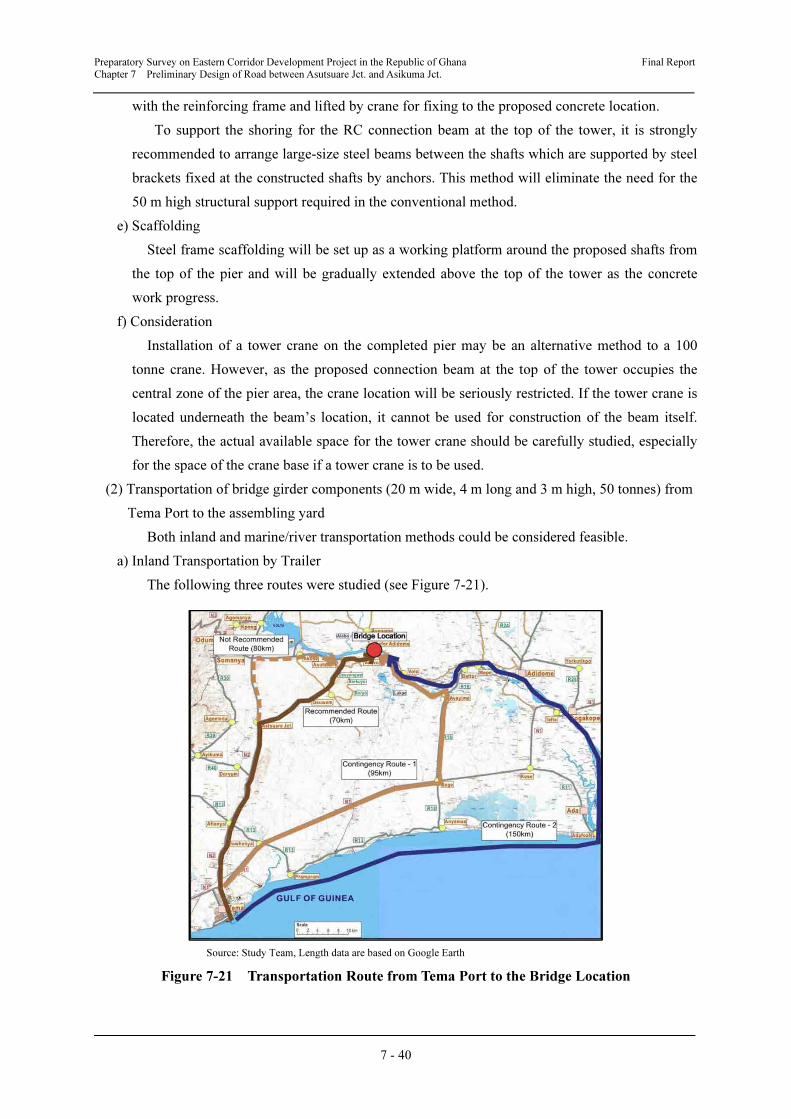
Preparatory Survey on Eastern Corridor Development Project in the Republic of Ghana Final Report
Chapter 7 Preliminary Design of Road between Asutsuare Jct. and Asikuma Jct.
7 - 40
with the reinforcing frame and lifted by crane for fixing to the proposed concrete location.
To support the shoring for the RC connection beam at the top of the tower, it is strongly
recommended to arrange large-size steel beams between the shafts which are supported by steel
brackets fixed at the constructed shafts by anchors. This method will eliminate the need for the
50 m high structural support required in the conventional method.
e) Scaffolding
Steel frame scaffolding will be set up as a working platform around the proposed shafts from
the top of the pier and will be gradually extended above the top of the tower as the concrete
work progress.
f) Consideration
Installation of a tower crane on the completed pier may be an alternative method to a 100
tonne crane. However, as the proposed connection beam at the top of the tower occupies the
central zone of the pier area, the crane location will be seriously restricted. If the tower crane is
located underneath the beam’s location, it cannot be used for construction of the beam itself.
Therefore, the actual available space for the tower crane should be carefully studied, especially
for the space of the crane base if a tower crane is to be used.
(2) Transportation of bridge girder components (20 m wide, 4 m long and 3 m high, 50 tonnes) from
Tema Port to the assembling yard
Both inland and marine/river transportation methods could be considered feasible.
a) Inland Transportation by Trailer
The following three routes were studied (see Figure 7-21).
Source: Study Team, Length data are based on Google Earth
Figure 7-21 Transportation Route from Tema Port to the Bridge Location
Preparatory Survey on Eastern Corridor Development Project in the Republic of Ghana Final Report
Chapter 7 Preliminary Design of Road between Asutsuare Jct. and Asikuma Jct.
7 - 41
1) Route-1 (70 km) - Feasible and Recommended
Tema Port - N2 - Asutsuare Junction - Asutsuare - Volivo (assembling yard)
This route is the best route. It is preferable that the proposed road improvement work between
Asutsuare Junction – Asutsuare – Volivo is completed before transportation is commenced. If
the improvement work is not completed, the following additional measures have to be taken:
• Repair and maintain the partially damaged Double Bituminous Surface Treatment (DBST)
roads between Asutsuare Junction and Asutsuare.
• Carry out regular maintenance on earth roads between Asutsuare and Volivo
2) Route -2 (80 km) - Not Feasible
• Tema Port - N2 – Akuse Junction - Akuse - Asutsuare - Volivo (assembling yard)
• It was found by investigation on site that the existing Bailey Bridge near Akuse is clearly
not strong enough to bear the load of a trailer with 50-tonne girder. Reinforcement of the
bridge is not realistic structurally in the view of its length (58m).
3) Route-3 (95km) - Feasible, Contingency route -1
Tema Port - N1 – Sege – Aveyime - Volivo (assembling yard)
This route is about 25 km longer than Route-1. Due to the current busy traffic conditions
caused by heavy transport vehicles between Sege and Aveyime, the road is expected to be
damaged and frequent repair work will become necessary. The overall road condition is
observed to be similar to that of Route-1, so its longer distance will be a disadvantage. However,
this route is contingency plan for Route 1.
b) Marine + River Transportation by Barge (150km) feasible–Contingency plan-2
In this option, imported girders from the manufacturing country should be temporarily
stocked at the port and loaded onto barges (flat pontoons) by means of port facilities. The barges
carrying the girders will be towed by tug boat up the Volta River to the assembling yard. A 200
tonne crane is required to unload them at the yard.
Due to towing against the river stream and the considerably longer transportation distance,
one trip, including loading and unloading time, may take two days. However, it is a valuable
contingency route in case the land routes become difficult due to unforeseen incidents. The
following potential hazards should be taken into consideration if it becomes necessary to use
this route.
• There is space restriction underneath the Lower Volta Bridge (horizontally 28 m and
vertically 7m)
• There may be shallow spots of less than 2 m water depth within the intended course in the
river.
• Schedule management for usage of the facility is required, as the unloading facility at the
assembling yard will also be used for loading of assembled girders and construction
materials for the pier on the opposite side.
It is concluded that land transportation will be more economical and faster even though some
additional cost is required for repair and maintenance of roads.
Preparatory Survey on Eastern Corridor Development Project in the Republic of Ghana Final Report
Chapter 7 Preliminary Design of Road between Asutsuare Jct. and Asikuma Jct.
7 - 42
(3) Consideration on Construction Plants
a) Cost Estimates for Construction Plants
The cost estimation for the main construction plants should be based on the assumption of
importation from other countries including Japan because there are no plant manufacturers in
Ghana. The leasing cost of such plants is therefore extremely high.
b) Concrete Batching Plant
The quantity of concrete required for the proposed new bridge across the Volta River will be
around 8,000– 9,000 m3 in total including both side abutments. It will not be economical to
establish batching plants for this quantity. However, for the assurance of quality and timely
supply of concrete, it is recommended to establish one batching plant somewhere on both sides
of the river. These batching plants can also be used for the construction of other concrete
structures such as small bridges, middle bridges, box culverts and so on for the project.
7.4.4 Temporary Work for Construction of Bridge across the Volta River
In comparison with the road construction sections, construction of a long bridge across the
Volta River will require a greater variety and larger scale of temporary works, which will
consequently account for a considerable share of the total cost of bridge construction. Some
examples of temporary works are introduced below, and are used as assumptions for estimating
the cost of temporary works in the Study.
(1) Steel-pipe Pile Cofferdam for Footing and Pier Construction
The proposed main piers are located in the river about 120 m away from both riverbanks. The
foundation of the reinforced concrete piers is designed as a spread footing, which is placed
directly on the rock bed underneath the riverbed. As all of the construction activities related to
such structures have to be carried out in the river, a cofferdam must be provided so that the
works can be carried out in dry conditions.
In order to carry out piling work effectively to overcome the existing rock bed and to
completely exclude the river water, a steel pipe pile cofferdam is considered to be the most
suitable method.
a) Shape and Size of Cofferdam
Considering the size of the inner structure, the horizontal area of the cofferdam is required to
be about 32 m by 15 m. 1,000 mm diameter steel pipe piles will be used (see Figure 7-22).
b) Method of Piling
Piling will be performed on the temporary deck as described below. The piles must be
penetrated into the rock through the riverbed to ensure that no water penetrates 1,400 mm
diameter holes will be drilled 3 m deep into the rock bed by a rock boring machine for installing
the 1,000 mm diameter steel pipe piles with connection accessories. Upon completion of piling
work and completely closing the cofferdam, the gaps around the piles and pile connections will
be thoroughly filled with cement mortar by grouting to protect the cofferdam from water ingress.
The pile heads will be cut off at the same level as the temporary deck surface.
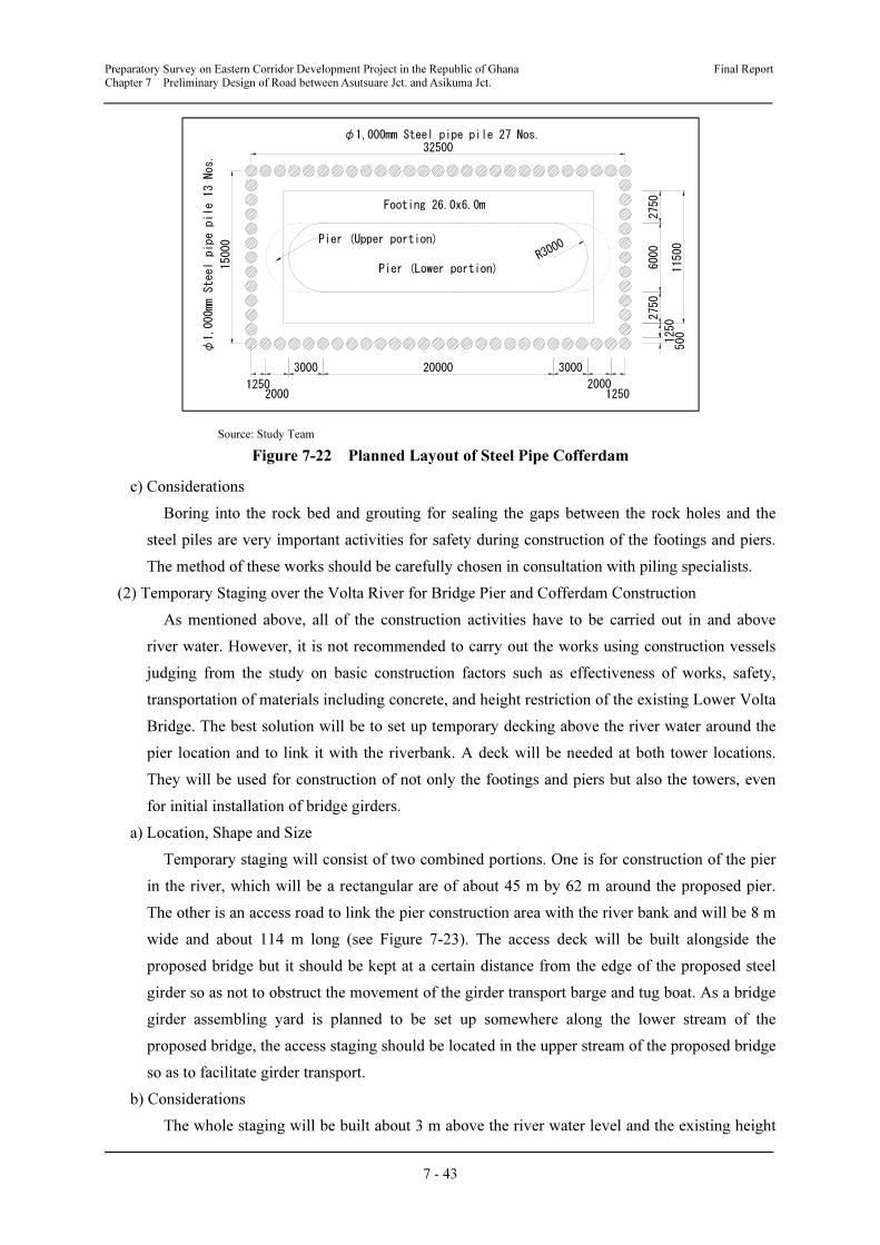
Preparatory Survey on Eastern Corridor Development Project in the Republic of Ghana Final Report
Chapter 7 Preliminary Design of Road between Asutsuare Jct. and Asikuma Jct.
7 - 43
Source: Study Team
Figure 7-22 Planned Layout of Steel Pipe Cofferdam
c) Considerations
Boring into the rock bed and grouting for sealing the gaps between the rock holes and the
steel piles are very important activities for safety during construction of the footings and piers.
The method of these works should be carefully chosen in consultation with piling specialists.
(2) Temporary Staging over the Volta River for Bridge Pier and Cofferdam Construction
As mentioned above, all of the construction activities have to be carried out in and above
river water. However, it is not recommended to carry out the works using construction vessels
judging from the study on basic construction factors such as effectiveness of works, safety,
transportation of materials including concrete, and height restriction of the existing Lower Volta
Bridge. The best solution will be to set up temporary decking above the river water around the
pier location and to link it with the riverbank. A deck will be needed at both tower locations.
They will be used for construction of not only the footings and piers but also the towers, even
for initial installation of bridge girders.
a) Location, Shape and Size
Temporary staging will consist of two combined portions. One is for construction of the pier
in the river, which will be a rectangular are of about 45 m by 62 m around the proposed pier.
The other is an access road to link the pier construction area with the river bank and will be 8 m
wide and about 114 m long (see Figure 7-23). The access deck will be built alongside the
proposed bridge but it should be kept at a certain distance from the edge of the proposed steel
girder so as not to obstruct the movement of the girder transport barge and tug boat. As a bridge
girder assembling yard is planned to be set up somewhere along the lower stream of the
proposed bridge, the access staging should be located in the upper stream of the proposed bridge
so as to facilitate girder transport.
b) Considerations
The whole staging will be built about 3 m above the river water level and the existing height
R3000
15000
φ1,000mm Steel pipe pile 27 Nos.
φ1,000mm Steel pipe pile 13 Nos.
Pier (Lower portion)
Pier (Upper portion)
2750
6000
2750
1250
500
11500
3000 20000 3000
200012502000
Footing 26.0x6.0m
32500
1250
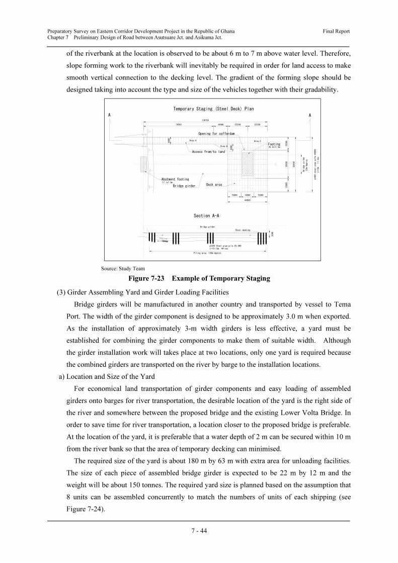
Preparatory Survey on Eastern Corridor Development Project in the Republic of Ghana Final Report
Chapter 7 Preliminary Design of Road between Asutsuare Jct. and Asikuma Jct.
7 - 44
of the riverbank at the location is observed to be about 6 m to 7 m above water level. Therefore,
slope forming work to the riverbank will inevitably be required in order for land access to make
smooth vertical connection to the decking level. The gradient of the forming slope should be
designed taking into account the type and size of the vehicles together with their gradability.
Source: Study Team
Figure 7-23 Example of Temporary Staging
(3) Girder Assembling Yard and Girder Loading Facilities
Bridge girders will be manufactured in another country and transported by vessel to Tema
Port. The width of the girder component is designed to be approximately 3.0 m when exported.
As the installation of approximately 3-m width girders is less effective, a yard must be
established for combining the girder components to make them of suitable width. Although
the girder installation work will takes place at two locations, only one yard is required because
the combined girders are transported on the river by barge to the installation locations.
a) Location and Size of the Yard
For economical land transportation of girder components and easy loading of assembled
girders onto barges for river transportation, the desirable location of the yard is the right side of
the river and somewhere between the proposed bridge and the existing Lower Volta Bridge. In
order to save time for river transportation, a location closer to the proposed bridge is preferable.
At the location of the yard, it is preferable that a water depth of 2 m can be secured within 10 m
from the river bank so that the area of temporary decking can minimised.
The required size of the yard is about 180 m by 63 m with extra area for unloading facilities.
The size of each piece of assembled bridge girder is expected to be 22 m by 12 m and the
weight will be about 150 tonnes. The required yard size is planned based on the assumption that
8 units can be assembled concurrently to match the numbers of units of each shipping (see
Figure 7-24).
Opening for cofferdam
Footing26.0x11.5m
Deck area
Access from/to land
Bridge girder
79250 16000 22250 22250
8000
8000
139750
Abutment footing17.1x7.0m
15000 14500 15000
44500
Area A
Area B
Area C
15000
32000
15000
62000
Bridge girder
22m Approx.
φ600 steel pipe pile @6000
L=13m 11 nos.
Bridge girder
Piling area: 130m Approx.
φ600 Steel pipe pile @3,000
L=10-13m, 44 nos.
Rock bed
River bed
Steel decking
3000
A A
Temporary Staging (Steel Deck) Plan
Section A-A
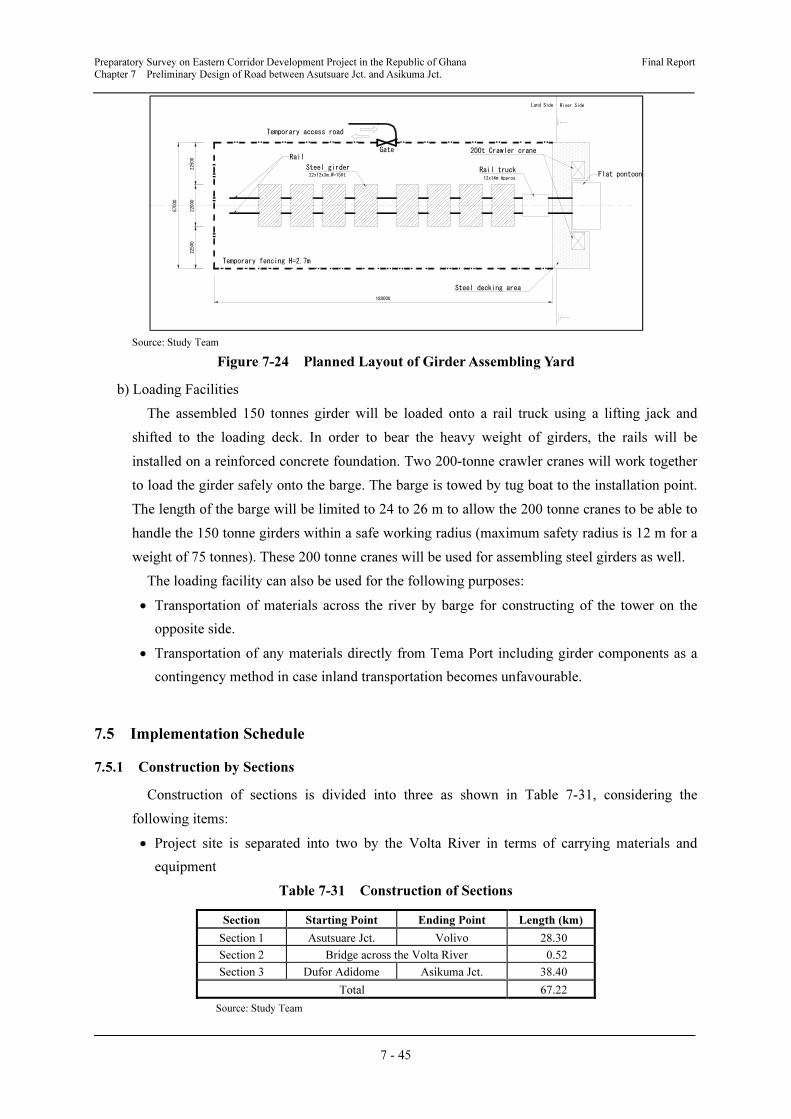
Preparatory Survey on Eastern Corridor Development Project in the Republic of Ghana Final Report
Chapter 7 Preliminary Design of Road between Asutsuare Jct. and Asikuma Jct.
7 - 45
Source: Study Team
Figure 7-24 Planned Layout of Girder Assembling Yard
b) Loading Facilities
The assembled 150 tonnes girder will be loaded onto a rail truck using a lifting jack and
shifted to the loading deck. In order to bear the heavy weight of girders, the rails will be
installed on a reinforced concrete foundation. Two 200-tonne crawler cranes will work together
to load the girder safely onto the barge. The barge is towed by tug boat to the installation point.
The length of the barge will be limited to 24 to 26 m to allow the 200 tonne cranes to be able to
handle the 150 tonne girders within a safe working radius (maximum safety radius is 12 m for a
weight of 75 tonnes). These 200 tonne cranes will be used for assembling steel girders as well.
The loading facility can also be used for the following purposes:
• Transportation of materials across the river by barge for constructing of the tower on the
opposite side.
• Transportation of any materials directly from Tema Port including girder components as a
contingency method in case inland transportation becomes unfavourable.
7.5 Implementation Schedule
7.5.1 Construction by Sections
Construction of sections is divided into three as shown in Table 7-31, considering the
following items:
• Project site is separated into two by the Volta River in terms of carrying materials and
equipment
Table 7-31 Construction of Sections
Section Starting Point Ending Point Length (km)
Section 1 Asutsuare Jct. Volivo 28.30
Section 2 Bridge across the Volta River 0.52
Section 3 Dufor Adidome Asikuma Jct. 38.40
Total 67.22
Source: Study Team
Steel girder22x12x3m,W=150t
Rail truck12x14m Approx.
200t Crawler craneRail
Land Side River Side
Flat pontoon
Temporary access road
Steel decking area
Temporary fencing H=2.7m
67000
22500
22000
22500
Gate
180000
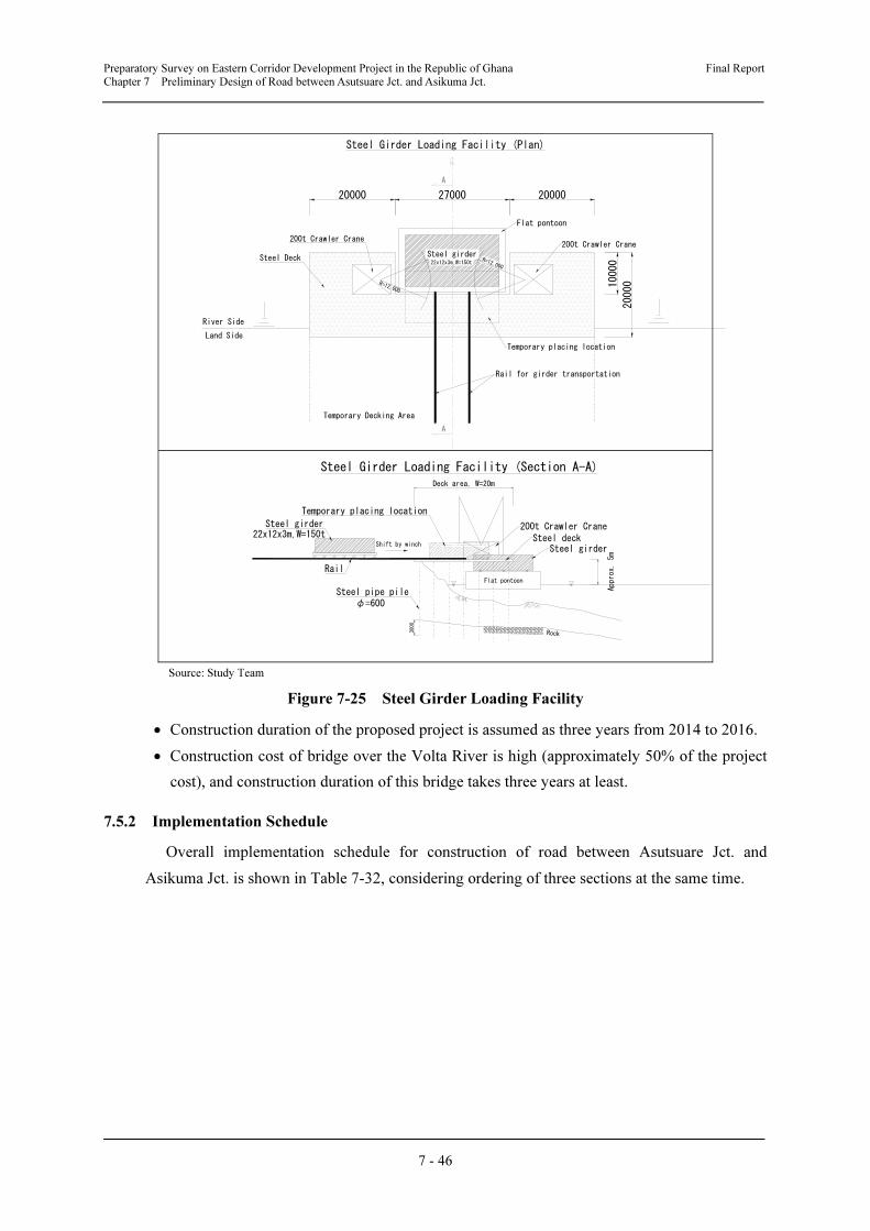
Preparatory Survey on Eastern Corridor Development Project in the Republic of Ghana Final Report
Chapter 7 Preliminary Design of Road between Asutsuare Jct. and Asikuma Jct.
7 - 46
Source: Study Team
Figure 7-25 Steel Girder Loading Facility
• Construction duration of the proposed project is assumed as three years from 2014 to 2016.
• Construction cost of bridge over the Volta River is high (approximately 50% of the project
cost), and construction duration of this bridge takes three years at least.
7.5.2 Implementation Schedule
Overall implementation schedule for construction of road between Asutsuare Jct. and
Asikuma Jct. is shown in Table 7-32, considering ordering of three sections at the same time.
Steel girder
River Side
Land Side
22x12x3m,W=150t
R=12,000
R=12,000
200t Crawler Crane200t Crawler Crane
Steel Deck
Temporary placing location
Rail for girder transportation
Temporary Decking Area
20000
Flat pontoon
27000 20000
10000
20000
Steel Girder Loading Facility (Plan)
A
A
Steel girder22x12x3m,W=150t
Rock
Flat pontoon
Steel girder
200t Crawler Crane
Steel Girder Loading Facility (Section A-A)
Temporary placing location
Rail
Shift by winchSteel deck
Steel pipe pile
φ=600
Deck area, W=20m
3000
Approx. 5m
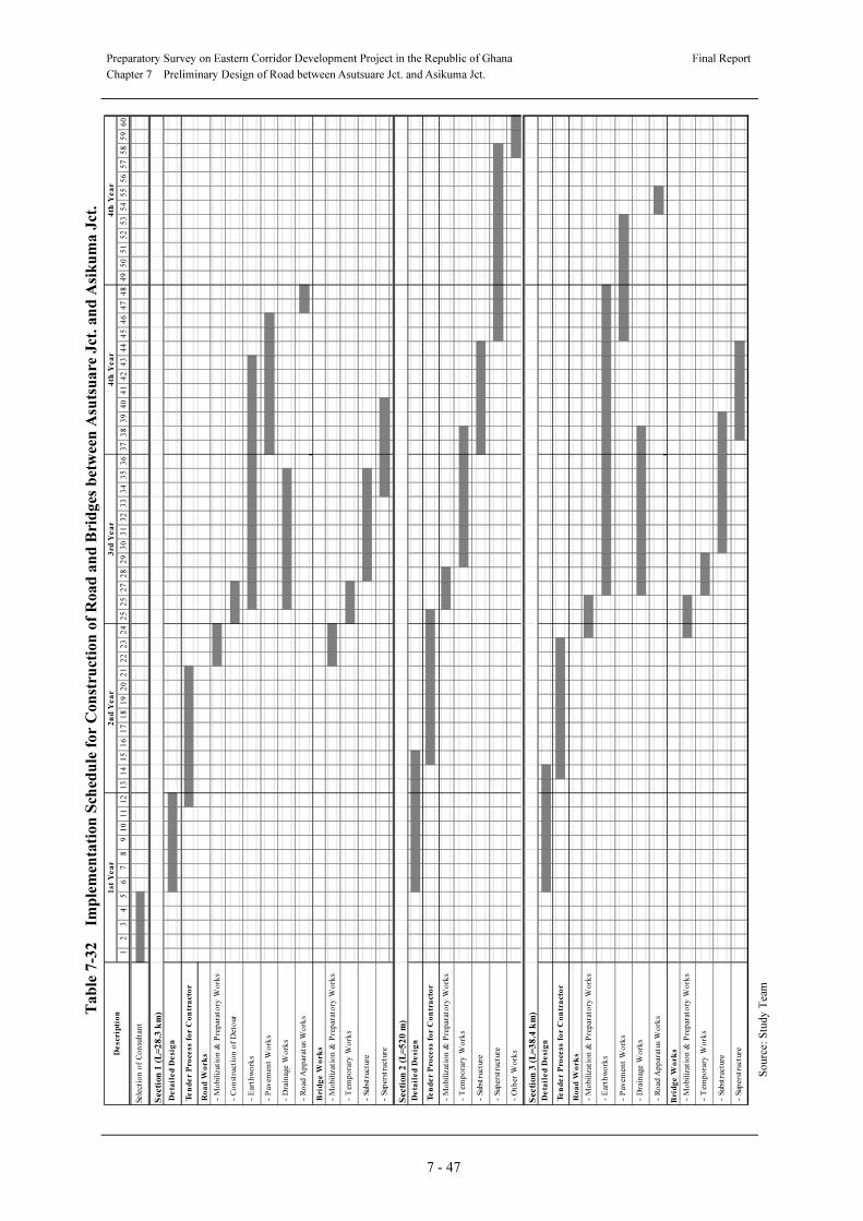
Preparatory Survey on Eastern Corridor Development Project in the Republic of Ghana
Final Report
Chapter 7 Preliminary Design of Road between Asutsuare Jct. and Asikuma Jct.
7 - 47
Ta
ble
7-3
2 Im
ple
men
tati
on
Sch
edu
le f
or
Co
nst
ruct
ion
of
Ro
ad
an
d B
rid
ges
bet
ween
Asu
tsu
are
Jct
. a
nd
Asi
ku
ma
Jct
.
So
urc
e: S
tud
y T
eam
12
34
56
78
91
01
11
21
31
41
51
61
71
81
92
02
12
22
32
42
52
52
72
82
93
03
13
23
33
43
53
63
73
83
94
04
14
24
34
44
54
64
74
84
95
05
15
25
35
45
55
65
75
85
96
0
Secti
on
1 (
L=
28
.3 k
m)
Ro
ad
Wo
rk
s
Bri
dg
e W
ork
s
Secti
on
2 (
L=
52
0 m
)
Secti
on
3 (
L=
38
.4 k
m)
Ro
ad
Wo
rk
s
Brid
ge
Wo
rk
s
- S
upers
truc
ture
- P
avem
en
t W
ork
s
- D
rain
age W
ork
s
- R
oad
Ap
para
tus
Wo
rks
- M
obi
lizat
ion
& P
rep
arat
ory
Wo
rks
- T
emp
ora
ry W
ork
s
- S
ubst
ruct
ure
- S
upers
truc
ture
- O
ther
Wo
rks
De
tail
ed
De
sig
n
Te
nd
er
Pro
cess f
or
Co
ntr
act
or
- M
obi
lizat
ion
& P
rep
arat
ory
Wo
rks
- E
arth
wo
rks
- S
upers
truc
ture
De
tail
ed
De
sig
n
Te
nd
er
Pro
cess f
or
Co
ntr
act
or
- M
obi
lizat
ion
& P
rep
arat
ory
Wo
rks
- T
emp
ora
ry W
ork
s
- S
ubst
ruct
ure
- P
avem
en
t W
ork
s
- D
rain
age W
ork
s
- R
oad
Ap
para
tus
Wo
rks
- M
obi
lizat
ion
& P
rep
arat
ory
Wo
rks
- T
emp
ora
ry W
ork
s
- S
ubst
ruct
ure
Sele
cti
on
of
Co
nsu
ltan
t
De
tail
ed
De
sig
n
Te
nd
er
Pro
cess f
or
Co
ntr
act
or
- M
obi
lizat
ion
& P
rep
arat
ory
Wo
rks
- C
on
stru
ctio
n o
f D
eto
ur
- E
arth
wo
rks
De
scr
ipti
on
1st
Ye
ar
2n
d Y
ea
r3
rd Y
ea
r4
th Y
ea
r4
th Y
ea
r