chapter 6 qc test for fluoroscopic equipment · pdf filechapter 6 qc test for fluoroscopic...
TRANSCRIPT
CHAPTER 6QC Test For Fluoroscopic Equipment
Prepared by:-Kamarul Amin bin Abdullah @ Abu Bakar
School of Medical ImagingKLMUC

Lesson Outcomes
• Describe the objectives of each QC test done.
• Identify QC tools and equipments involved in each QC test.
• Discuss the analysis of result of QC.
Contents of QC Fluoroscopic
A. Exposure rate
B. Beam alignment
C. Source-to-skin distance limits
D. Intensifier viewing system high contrast
E. Intensifier viewing system low contrast
F. TV monitors and recorders
G. Automatic brightness control
EXPOSURE RATE
Objective and Equipments
• To determine the variation in reproducibility over a number of exposures at the same generator setting.
• To determine the variation in average kV over a number of exposures at the same generator setting.
• To evaluate the linearity of generator for commonly used exposure settings.
• Phantom, dosimeter, stopwatch, digital kV meter, energized fluoroscopic unit
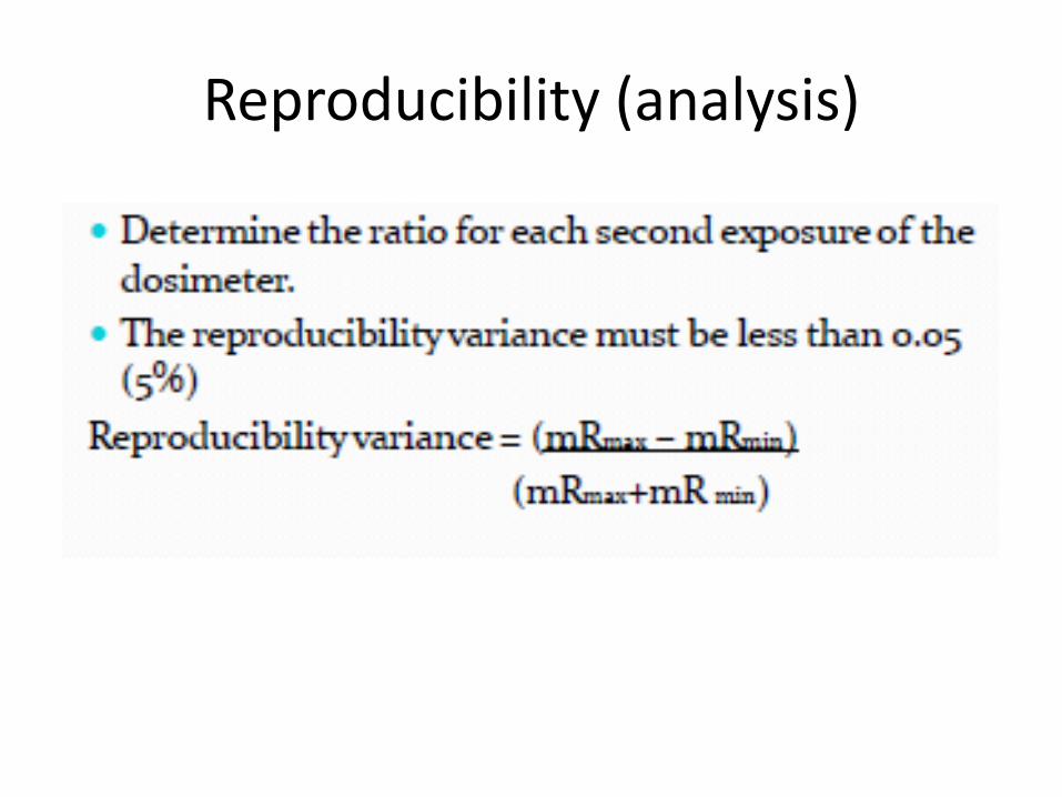
Reproducibility (analysis)
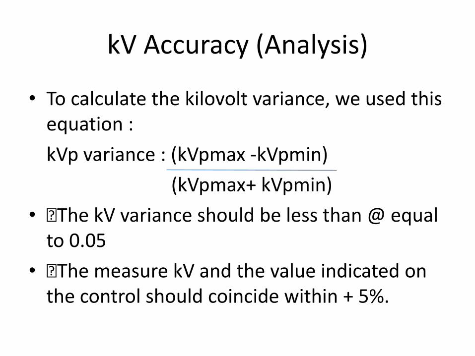
kV Accuracy (Analysis)
• To calculate the kilovolt variance, we used this equation :
kVp variance : (kVpmax -kVpmin)
(kVpmax+ kVpmin)
• The kV variance should be less than @ equal to 0.05
• The measure kV and the value indicated on the control should coincide within + 5%.
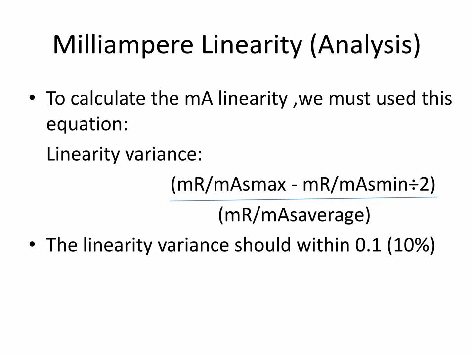
Milliampere Linearity (Analysis)
• To calculate the mA linearity ,we must used this equation:
Linearity variance:
(mR/mAsmax - mR/mAsmin÷2)
(mR/mAsaverage)
• The linearity variance should within 0.1 (10%)

BEAM ALIGNMENT
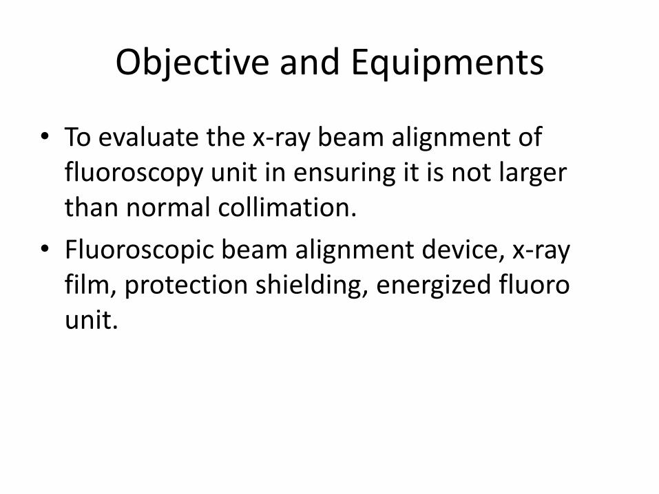
Objective and Equipments
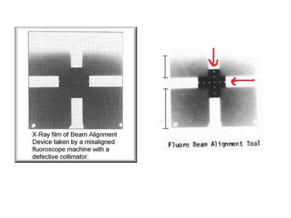
• To evaluate the x-ray beam alignment of fluoroscopy unit in ensuring it is not larger than normal collimation.
• Fluoroscopic beam alignment device, x-ray film, protection shielding, energized fluorounit.

Analysis
• Theedgesofthebeamfieldarenotinalign,thereforebeamfieldandimagereceptoraremisaligned.
• The center of the field is indicated by the central dot and any misalignment of the beam can be checked by counting the number of dots visible in each channel.
• Supposedly, the dot at the intersection of the two lines should be at the center of the image
• There should be an equal number of dots visible on each of the channels when counted from the centre.

SOURCE TO SKIN DISTANCE
Objective and Equipments
• To reduce the skin exposure to the patient as much as possible while still assuring that sufficient x-ray output is obtainable to perform the diagnostic procedure.
• Energized fluoro unit, measuring tape.

Analysis
Standard result:
• the source to skin distance must be not less than 15 inches (38cm) for stationary fluoroscopy
• for mobile fluoroscopy must be not less than 12 inches (30cm)
INTENSIFIER VIEWING SYSTEM HIGH CONTRAST
Objective and Equipments
Analysis
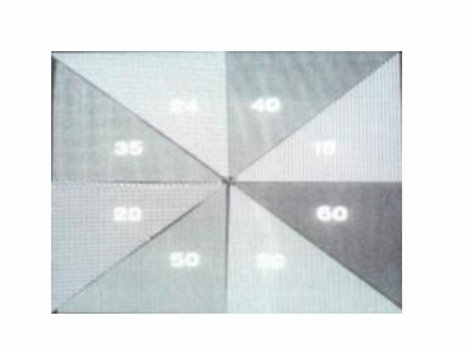
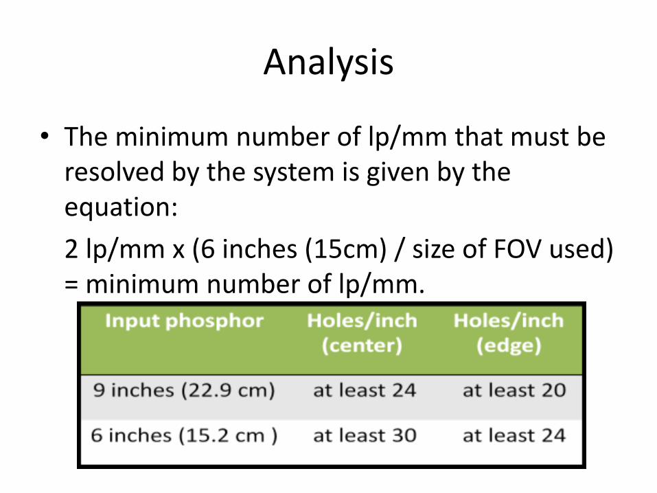
• The minimum number of lp/mm that must be resolved by the system is given by the equation:
2 lp/mm x (6 inches (15cm) / size of FOV used) = minimum number of lp/mm.
INTENSIFIER VIEWING SYSTEM LOW CONTRAST
Objective and Equipments
• To resolve relatively large objects that differ slightly in radiolucency from the surrounding area.
• Energized fluoroscopic unit, low contrast resolution test tool
Analysis
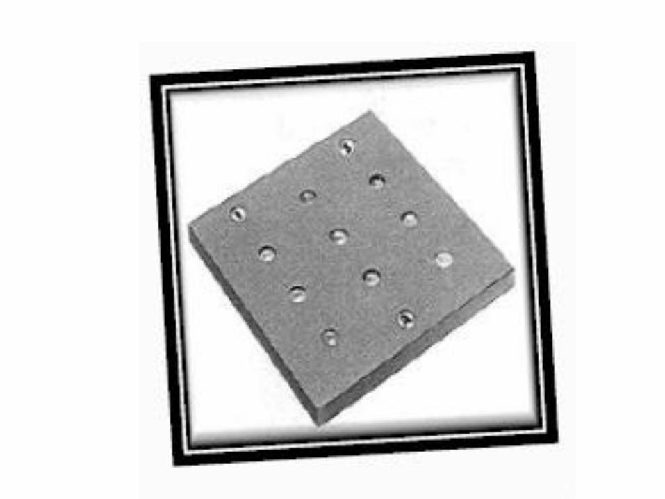
• When the plates are sandwiched together and imaged on a fluoroscopic system, low contrast evaluation can be made based on the shallowest visible hole.
• With the low contrast resolution test tool, the contrast between the holes and the surrounding area is 2%.
• with CDRH phantom, the two deepest holes should be visible clearly.
• Better system are able to visualize the smaller holes on the test tools or the shallower holes on the CDRH phantom.
TV MONITORS AND RECORDERS
Objective and Equipments
• To assure that the TV monitor and recorder are functioning properly.
• Energized fluoro unit, phantom , test tool
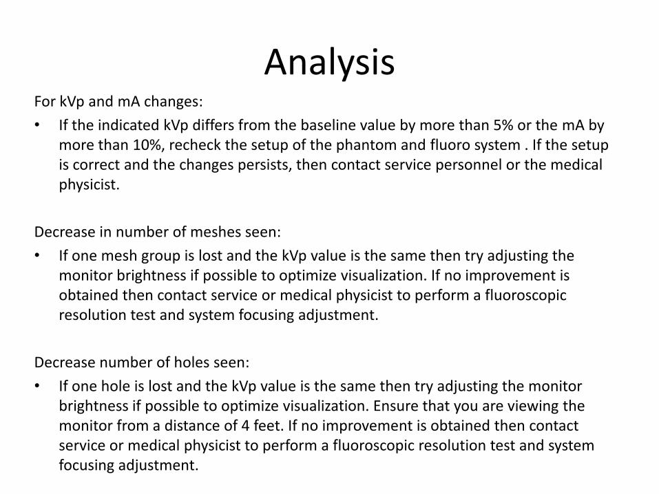
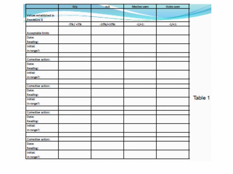
AnalysisFor kVp and mA changes:
• If the indicated kVp differs from the baseline value by more than 5% or the mA by more than 10%, recheck the setup of the phantom and fluoro system . If the setup is correct and the changes persists, then contact service personnel or the medical physicist.
Decrease in number of meshes seen:
• If one mesh group is lost and the kVp value is the same then try adjusting the monitor brightness if possible to optimize visualization. If no improvement is obtained then contact service or medical physicist to perform a fluoroscopic resolution test and system focusing adjustment.
Decrease number of holes seen:
• If one hole is lost and the kVp value is the same then try adjusting the monitor brightness if possible to optimize visualization. Ensure that you are viewing the monitor from a distance of 4 feet. If no improvement is obtained then contact service or medical physicist to perform a fluoroscopic resolution test and system focusing adjustment.
TEST TOOL
AUTOMATIC BRIGHTNESS CONTROL
Objective and Equipments
• To assure that the automatic brightness control are functioning properly.
• Energized fluoro unit, lead apron, phantom
Analysis
• As the thickness of structure increases, the brightness or contrast remain the same.
• ABC adjusts the contrast automatically.
• Allows the fluoroscopic unit to automatically maintain the brightness level of the image (variations of thickness and attenuation)