chapter 6: design guidelines - city of graham
TRANSCRIPT

6-� NOVEMBER 2006
GRAHAM PEDESTRIAN TRANSPORTATION PLAN DESIGN GUIDELINES
DESIGN GUIDELINES
T
Figure 6(a):Well designed residential sidewalk�.
Chapter 6
6.1 Overview
hese guidelines originate from and adhere to national design standards as defined by the American Association of State Highway Transportation Officials (AASHTO), the Americans with Disabilities Act (ADA), the Federal Highway Administration (FHWA) Pedestrian Facilities Users Guide, the Manual on Uniform Traffic Control Devices (MUTCD), and the NCDOT. Should the national standards be revised in the future and result in discrepancies with this chapter, the national standards should prevail for all design decisions. Likewise, all cost information provided is relevant only at or around the date of this report (September 2006). A qualified engineer or landscape architect should be consulted for the most up to date and accurate cost estimates. The sections below serve as an inventory of pedestrian design elements/treatments and provide guidelines for their development. These treatments and design guidelines are important because they represent minimum standards for creating a pedestrian-friendly, safe, accessible community, and have been tailored to meet the specific facility development needs of Graham’s pedestrian system. The guidelines are not, however, a substitute for a more thorough evaluation by a landscape architect or engineer upon implementation of facility improvements. Some improvements may also require cooperation with the NCDOT for specific design solutions.
6.2 Pedestrian Facility Elements
6.2.1 Sidewalks and WalkwaysSidewalks and walkways are extremely important public right-of-way components often times adjacent to, but separate from automobile traffic. In many ways, they act as the seam between private residences, stores, businesses, and the street. They are spaces where children play, neighbors meet and talk, shoppers meander casually, parents push strollers, and commuters walk to transit stops or directly to work. Because of the social importance of these spaces, great attention should be paid to retrofit and renovate areas with disconnected, dangerous, or otherwise malfunctioning walkways.
From a European style promenade to, in the case of a more rural environment, a simple asphalt or crushed stone path next to a secondary road, walkway form and topography

6-2 NOVEMBER 2006
GRAHAM PEDESTRIAN TRANSPORTATION PLANDESIGN GUIDELINES
can vary greatly. In general, sidewalks are constructed of concrete although there are some successful examples where other materials such as asphalt, crushed stone, or other slip resistant material have been used. The width of the walkways should correspond to the conditions present in any given location (i.e. level of pedestrian traffic, building setbacks, or other important natural or cultural features). FHWA (Federal Highway Administration) and the Institute of Transportation Engineers both suggest five feet as the minimum width for a sidewalk. This is considered ample room for two people to walk abreast or for two pedestrians to pass each other. Often downtown areas, near schools, transit stops, or other areas of high pedestrian activity call for much wider sidewalks.
Sidewalks are typically built in curb and gutter sections. They need to be kept completely free of obstructions such as utility poles. A four to eight foot buffer zone parallel to the sidewalk or walkway is recommended to separate pedestrian traffic from automobile traffic and to keep the sidewalk free of light pole obstructions. Much like the sidewalk and walkway itself, the form and topography of this buffer will vary greatly. Native street tree plantings have historically proven to work successfully within these buffer zones. They regulate micro-climate, create a desirable sense of enclosure, promote a local ecological identity and connection to place, and can act as a pleasant integration of nature into an urban environment. In the event that vegetation is not possible, a row of parked cars, bike lane, or street furniture can be used to create this buffer.
Guidelines3+9: • Concrete is preferred surface, providing the longest service life and requiring the least maintenance.• Sidewalks should be built as flat as possible to accommodate all pedestrians; they should have a running grade of five percent or less; with a two percent maximum cross-slope.• Concrete sidewalks should be built to minimum depth of four inches; six inches at driveways.• Sidewalks should be a minimum of five feet wide; eight to ten feet wide within Downtown; ten feet can also be considered in other areas of heavy pedestrian traffic. When sidewalk abuts storefronts, an additional two feet of space from walls is recommended.• Buffer zone of two to four feet in local or collector streets; five to six feet in arterial or major streets and up to eight feet in busy streets and Downtown to provide space for light poles and other street furniture.• Motor vehicle access points should be kept to minimum.
Figure 6(b):Sidewalk with a vegetative buffer zone. Notice the sense of enclosure created by the large canopy street trees�.
6-� NOVEMBER 2006
GRAHAM PEDESTRIAN TRANSPORTATION PLAN DESIGN GUIDELINES
Cost1 : Concrete curbing: $10-$15/linear foot Walkways: $3/square foot Asphalt walkways are much less expensive in terms of construction cost but more difficult to traverse and more expensive to maintain.
6.2.2 Greenway Trails
A greenway is defined as a linear corridor of land that can be either natural, such as rivers and streams, or manmade, such as abandoned railroad beds and utility corridors. Most greenways contain trails. Greenway trails can be paved or unpaved, and can be designed to accommodate a variety of trail users, including bicyclists, walkers, hikers, joggers, skaters, horseback riders, and those confined to wheelchairs.
Multi-use trails are the most common trail type in the nation. These trails vary in width and can accommodate a wide variety of users. The minimum width for two-directional trails is 10’, however 12’-14’ widths are preferred where heavy traffic is expected.
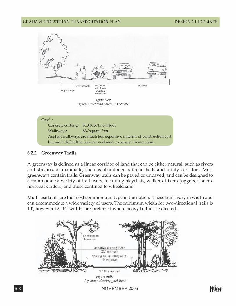
roadway5’-10’ sidewalk
5’-8’ grass edge
5’-8’ median with 3’ max height na-tive shrubs
Figure 6(c):Typical street with adjacent sidewalk
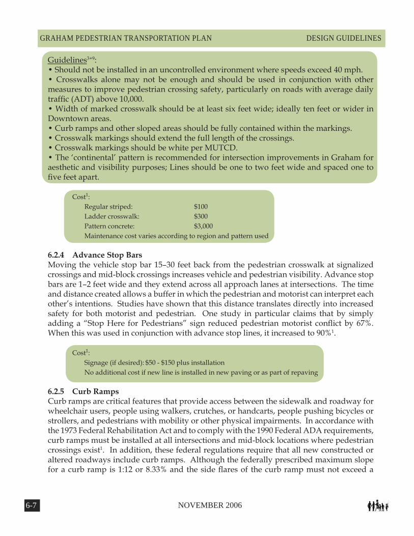
Figure 6(d):Vegetation clearing guidelines

6-� NOVEMBER 2006
GRAHAM PEDESTRIAN TRANSPORTATION PLANDESIGN GUIDELINES
Centerline stripes should be considered for paths that generate substantial amounts of pedestrian traffic. Possible conflicts between user groups must be considered during the design phase, as cyclists often travel at a faster speed than other users. Radii minimums should also be considered depending on the different user groups.
While the vegetative clearing needed for these trails varies with the width of the trail. The minimum width for clearing and grubbing a 14’ wide trail is 18' (two feet on each side). Selective thinning increases sight lines and distances and enhances the safety of the trail user. This practice includes removal of underbrush and limbs to create open pockets within a forest canopy, but does not include the removal of the forest canopy itself.
Typical pavement design for a paved, off-road, multi-use trail should be based upon the specific
Figure 6(e):Typical greenway trail approach to a roadway
Figure 6(f):Asphalt pavement construction detail

6-� NOVEMBER 2006
GRAHAM PEDESTRIAN TRANSPORTATION PLAN DESIGN GUIDELINES
loading and soil conditions for each project. These asphalt or concrete trails should be designed to withstand the loading requirements of occasional maintenance and emergency vehicles.
Concrete: In areas prone to frequent flooding, it is recommended that concrete be used because of its excellent durability. Concrete surfaces are capable of withstanding the most powerful environmental forces. They hold up well against the erosive action of water, root intrusion and subgrade deficiencies such as soft soils. Most often, concrete is used for intensive urban applications. Of all surface types, it is the strongest and has the lowest maintenance requirement, if it is properly installed.
Asphalt: Asphalt is a flexible pavement and can be installed on virtually any slope. One important concern for asphalt trails is the deterioration of trail edges. Installation of a geotextile fabric beneath a layer of aggregate base course (ABC) can help to maintain the edge of a trail. It is important to provide a 2’ wide graded shoulder to prevent trail edges from crumbling.
Trail and Roadway Intersections: The images below present detailed specifications for the layout of intersections between trail corridors and roadways. Signage rules for these sorts of intersections are available in the MUTCD as well. For further trail design, including design for roadway intersections, please see Trails for the Twenty-First Century: Planning Design, and Management Manual for Multi-use Trails.

6-6 NOVEMBER 2006
GRAHAM PEDESTRIAN TRANSPORTATION PLANDESIGN GUIDELINES
6.2.3 Marked CrosswalksA marked crosswalk designates a pedestrian right-of-way across a street. It is often installed at controlled intersections or at key locations along the street (a.k.a. mid-block crossings) and in this Plan are prescribed for the Downtown, school areas, and key residential and commercial areas where pedestrian activity is greatest. Although marked crosswalks provide strong visual clues to motorists that pedestrians are present, it is important to consider the use of these elements in conjunction with other traffic calming devices to fully recognize low traffic speeds and enhance pedestrian safety. In general, “marked crosswalks should not be installed in an uncontrolled environment where speeds exceed 40 mph”3. Every attempt should be made to install crossings in places where pedestrians are most likely to cross. A well-designed traffic calming location is not effective if pedestrians are using other unmodified and potentially dangerous locations to cross the street.
Marked pedestrian crosswalks may be used under the following conditions: 1) At locations with stop signs or traffic signals, 2) At non-signalized street crossing locations in designated school zones, and 3) At non-signalized locations where engineering judgment dictates that the use of specifically designated crosswalks are desirable9.
There is a variety of form, pattern, and materials to choose from when creating a marked crosswalk. It is important however to provide crosswalks that are not slippery, are free of tripping hazards, or are otherwise difficult to maneuver by any person including those
with physical mobility or vision impairments. Although attractive materials such as inlaid stone or certain types of brick may provide character and aesthetic value, the crosswalk can become slippery. Also, as it degrades from use or if it is improperly installed, it may become a hazard for the mobility or vision impaired.
A variety of color or texture may be used to designate crossings. These materials should be smooth, skid-resistant, and visible3. Reflective paint is inexpensive but is considered more slippery than other devices such as inlay tape or thermoplastic. A variety of patterns may be employed as detailed in Figure 6(g). In areas with a high volume of pedestrian traffic, particularly at mid-block crossings, a crosswalk can be raised to create both a physical impediment for automobiles and a reinforced visual clue to the motorist.
An engineering study may need to be performed to determine the appropriate width of a crosswalk at a given location, however marked crosswalks should not be less than six feet in width. In downtown areas or other locations of high pedestrian traffic, a width of ten feet or greater should be considered.
Figure 6(g):Illustration of all the variety of patterns possible in designating a crosswalk�.
6-� NOVEMBER 2006
GRAHAM PEDESTRIAN TRANSPORTATION PLAN DESIGN GUIDELINES
Guidelines3+9: • Should not be installed in an uncontrolled environment where speeds exceed 40 mph.• Crosswalks alone may not be enough and should be used in conjunction with other measures to improve pedestrian crossing safety, particularly on roads with average daily traffic (ADT) above 10,000.• Width of marked crosswalk should be at least six feet wide; ideally ten feet or wider in Downtown areas.• Curb ramps and other sloped areas should be fully contained within the markings.• Crosswalk markings should extend the full length of the crossings.• Crosswalk markings should be white per MUTCD. • The ‘continental’ pattern is recommended for intersection improvements in Graham for aesthetic and visibility purposes; Lines should be one to two feet wide and spaced one to five feet apart.
Cost1: Regular striped: $100 Ladder crosswalk: $300 Pattern concrete: $3,000 Maintenance cost varies according to region and pattern used
6.2.4 Advance Stop BarsMoving the vehicle stop bar 15–30 feet back from the pedestrian crosswalk at signalized crossings and mid-block crossings increases vehicle and pedestrian visibility. Advance stop bars are 1–2 feet wide and they extend across all approach lanes at intersections. The time and distance created allows a buffer in which the pedestrian and motorist can interpret each other’s intentions. Studies have shown that this distance translates directly into increased safety for both motorist and pedestrian. One study in particular claims that by simply adding a “Stop Here for Pedestrians” sign reduced pedestrian motorist conflict by 67%. When this was used in conjunction with advance stop lines, it increased to 90%1.
Cost1: Signage (if desired): $50 - $150 plus installation No additional cost if new line is installed in new paving or as part of repaving
6.2.5 Curb RampsCurb ramps are critical features that provide access between the sidewalk and roadway for wheelchair users, people using walkers, crutches, or handcarts, people pushing bicycles or strollers, and pedestrians with mobility or other physical impairments. In accordance with the 1973 Federal Rehabilitation Act and to comply with the 1990 Federal ADA requirements, curb ramps must be installed at all intersections and mid-block locations where pedestrian crossings exist1. In addition, these federal regulations require that all new constructed or altered roadways include curb ramps. Although the federally prescribed maximum slope for a curb ramp is 1:12 or 8.33% and the side flares of the curb ramp must not exceed a

6-� NOVEMBER 2006
GRAHAM PEDESTRIAN TRANSPORTATION PLANDESIGN GUIDELINES
Figure 6(h):Curb ramps shown have two separate ramps at the intersection�.
maximum slope of 1:10 or 10.0%, it is recommended that much less steep slopes be used whenever possible.
It is also recommended that two separate curb ramps be provided at each intersection (Figure 6(h)). With only one large curb ramp serving the entire corner, there is not safe connectivity for the pedestrian. Dangerous conditions exist when the single, large curb ramp inadvertently directs a pedestrian into the center of the intersection, or in front of an unsuspecting, turning
vehicle.
For additional information on curb ramps see Accessible Rights-of-Way: A Design Guide, by the U.S. Access Board and the Federal Highway Administration, and Designing Sidewalks and Trails for Access, Parts I and II, by the Federal Highway Administration. Visit: www.access-board.gov for the Access board’s right-of-way report1.
Guidelines9: • Two separate curb ramps, one for each crosswalk, should be provided at corner of an intersection.• Curb ramp should have a slope no greater than 1:12 (8.33%). Side flares should not exceed 1:10 (10%).
Cost1: Curb ramp: $800 - $1,500 per ramp (new or retrofit)
6.2.6 Raised or Lowered MediansMedians are barriers in the center portion of a street or roadway1. When used in conjunction with mid-block or intersection crossings, they can be used as a crossing island to provide a place of refuge for pedestrians. They also provide opportunities for landscaping that in turn can help to slow traffic. A center turn lane can be converted into a raised or lowered median thus increasing motorist safety.
A continuous median can present several problems when used inappropriately. If all left-turn opportunities are removed, there runs a possibility for increased traffic speeds and unsafe U-turns at intersections. Additionally, the space occupied may be taking up room that could be used for bike lanes or other treatments discussed in this chapter. An alternative to the continuous median is to create a segmented median with left turn opportunities.
Raised or lowered medians are best suited for high-volume, high-speed roads, and they should provide ample cues for people with visual impairments to identify the boundary between the crossing island and the roadway.
6-� NOVEMBER 2006
GRAHAM PEDESTRIAN TRANSPORTATION PLAN DESIGN GUIDELINES
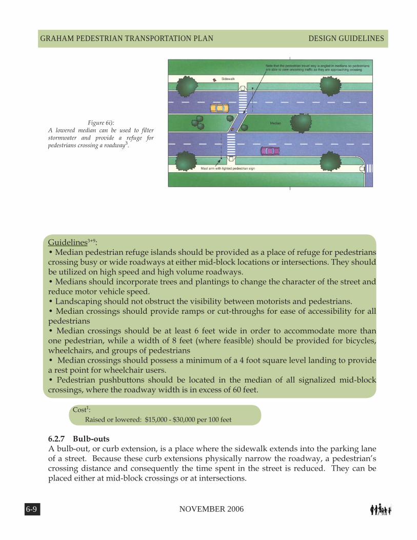
Figure 6i):A lowered median can be used to filter stormwater and provide a refuge for pedestrians crossing a roadway�.
Guidelines3+9: • Median pedestrian refuge islands should be provided as a place of refuge for pedestrians crossing busy or wide roadways at either mid-block locations or intersections. They should be utilized on high speed and high volume roadways.• Medians should incorporate trees and plantings to change the character of the street and reduce motor vehicle speed.• Landscaping should not obstruct the visibility between motorists and pedestrians.• Median crossings should provide ramps or cut-throughs for ease of accessibility for all pedestrians • Median crossings should be at least 6 feet wide in order to accommodate more than one pedestrian, while a width of 8 feet (where feasible) should be provided for bicycles, wheelchairs, and groups of pedestrians• Median crossings should possess a minimum of a 4 foot square level landing to provide a rest point for wheelchair users. • Pedestrian pushbuttons should be located in the median of all signalized mid-block crossings, where the roadway width is in excess of 60 feet. Cost1:
Raised or lowered: $15,000 - $30,000 per 100 feet
6.2.7 Bulb-outsA bulb-out, or curb extension, is a place where the sidewalk extends into the parking lane of a street. Because these curb extensions physically narrow the roadway, a pedestrian’s crossing distance and consequently the time spent in the street is reduced. They can be placed either at mid-block crossings or at intersections.

6-�0 NOVEMBER 2006
GRAHAM PEDESTRIAN TRANSPORTATION PLANDESIGN GUIDELINES
Figure 6(j):By reducing a pedestrian’s crossing distance, less time is spent in the roadway, and pedestrian vehicle conflicts are reduced.�
Sightlines and pedestrian visibility are reduced when motor vehicle parking encroaches too close to corners creating a dangerous situation for pedestrians. When placed at an intersection, bulb-outs preclude vehicle parking too close to a crosswalk. Also, bulb-outs at intersections can greatly reduce turning speed, especially if curb radii are set as tight as possible1. Finally, bulb-outs also reduce travel speeds when used in mid-block crossings because of the reduced street width.
Bulb-outs should only be used where there is an existing on-street parking lane and should never encroach into travel lanes, bike lanes, or shoulders1.
Guidelines10 :• Bulb-outs should be used on crosswalks in heavy pedestrian areas where parking may limit the driver’s view of the pedestrian.• Where used, sidewalk bulb-outs should extend into the street for the width of a parking lane (a minimum five feet) in order to provide for a shorter crossing width, increased pedestrian visibility, more space for pedestrian queuing, and a place for sidewalk amenities and planting.• Curb extensions should be used on mid-block crossing where feasible.• Curb extensions may be inappropriate for use on corners where frequent right turns are made by trucks or buses.
Cost1: Bulb-outs/Curb extensions: $2,000 - $20,000 Cost can increase depending on the amount of infrastructure that may have to be relocated.
6.2.8 Pedestrian Overpass/UnderpassPedestrian overpasses and underpasses efficiently allow for pedestrian movement across busy thoroughfares1. These types of facilities are problematic in many regards and should only be considered under suitable circumstances or where no other solution is possible.

6-�� NOVEMBER 2006
GRAHAM PEDESTRIAN TRANSPORTATION PLAN DESIGN GUIDELINES
Perhaps the best argument for using them sparingly is that research proves pedestrians will avoid using such a facility if they perceive the ability to cross at grade as taking about the same amount of time1.
The other areas of contention arise with the high cost of construction. There are also ADA requirements for stairs, ramps, and elevators that in many cases once complied with result in an enormous structure that is visually disruptive and difficult to access.
Overpasses work best when existing topography allows for smooth transitions. Underpasses as well work best with favorable topography when they are open and accessible, and exhibit a sense of safety1. Each should only be considered with rail lines, high volume traffic areas such as freeways, and other high volume arteries1.
Guidelines10 : • Over and underpasses should be considered only for crossing arterials with greater thanOver and underpasses should be considered only for crossing arterials with greater than 20,000 vehicle trips per day and speeds 35 - 40 mph and over.• Minimum widths for over and underpasses should follow the guidelines for sidewalk width.• Underpasses should have a daytime illuminace minimum of 10 fc achievable through artificial and/or natural light provided through an open gap to sky between the two sets of highway lanes, and a night time level of 4 foot-candle.• In underpasses, where vertical clearance allows, the pedestrian walkway should be separated from the roadway by more than a standard curb height.• Consider acoustics measures within underpasses to reduce noise impacts to pedestrians and bicyclists.
Cost: Varies greatly from $500,000 to $4,000,000
6.2.9 RoundaboutsA roundabout is a circular intersection that maneuvers traffic around in a counterclockwise direction so that cars make a right-hand turn onto a desired street1. Vehicles from approaching streets are generally not required to stop although approaching vehicles are required to yield to motorists in the roundabout. It is believed that this system eliminates certain types of crashes at traditional intersections.
Roundabout design can become quite problematic in dealing with pedestrian and bicycle use. Every effort must be made to prompt motorists to yield to pedestrians crossing the roundabout. A low design speed is required to improve pedestrian safety. Splitter islands and single lane approaches both lend to pedestrian safety as well as other urban design elements discussed in this chapter.
Problems also arise with the vision-impaired because there are not proper audible cues
6-�2 NOVEMBER 2006
GRAHAM PEDESTRIAN TRANSPORTATION PLANDESIGN GUIDELINES
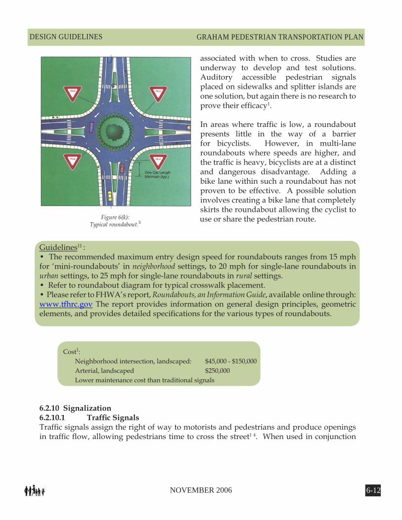
Figure 6(k):Typical roundabout.�
associated with when to cross. Studies are underway to develop and test solutions. Auditory accessible pedestrian signals placed on sidewalks and splitter islands are one solution, but again there is no research to prove their efficacy1.
In areas where traffic is low, a roundabout presents little in the way of a barrier for bicyclists. However, in multi-lane roundabouts where speeds are higher, and the traffic is heavy, bicyclists are at a distinct and dangerous disadvantage. Adding a bike lane within such a roundabout has not proven to be effective. A possible solution involves creating a bike lane that completely skirts the roundabout allowing the cyclist to use or share the pedestrian route.
Guidelines11 : • The recommended maximum entry design speed for roundabouts ranges from 15 mph for ‘mini-roundabouts’ in neighborhood settings, to 20 mph for single-lane roundabouts in urban settings, to 25 mph for single-lane roundabouts in rural settings.• Refer to roundabout diagram for typical crosswalk placement.• Please refer to FHWA’s report, Roundabouts, an Information Guide, available online through: www.tfhrc.gov The report provides information on general design principles, geometric elements, and provides detailed specifications for the various types of roundabouts.
Cost1: Neighborhood intersection, landscaped: $45,000 - $150,000 Arterial, landscaped $250,000 Lower maintenance cost than traditional signals
6.2.10 Signalization6.2.10.1 TrafficSignalsTraffic signals assign the right of way to motorists and pedestrians and produce openings in traffic flow, allowing pedestrians time to cross the street1 4. When used in conjunction
6-�� NOVEMBER 2006
GRAHAM PEDESTRIAN TRANSPORTATION PLAN DESIGN GUIDELINES
with pedestrian friendly design, proper signalization should allow for an adequate amount of time for an individual to cross the street. The suggested amount of pedestrian travel speed recommended in the Manual on Uniform Traffic Control Devices (MUTCD) is 4ft/sec however this does not address the walking speed of the elderly or children. Therefore it is suggested that a lower speed of 3.5ft/sec be used whenever there are adequate numbers of elderly and children using an area.
Engineering, as well as urban design judgment, must be used when determining the location of traffic signals and the accompanying timing intervals. Although warrants for pedestrian signal timing have been produced by the MUTCD, each site must be analyzed for factors including new facility and amenity construction (i.e. a popular new park or museum) to allow for potential future pedestrian traffic volume. In addition, creating better access to existing places may in fact generate a higher pedestrian volume1.
Fixed timed sequencing is often used in high traffic volume commercial or downtown areas to allow for a greater efficiency of traffic flow. In such instances, the pedestrian speed must be carefully checked to ensure safety.
6.2.10.2 Pedestrian SignalsThere are a host of possible traffic signal enhancement opportunities that can greatly improve the safety and flow of pedestrian traffic. Some include: international symbols for WALK and DON’T WALK, providing large traffic signals, the positioning of traffic signals so that those waiting at a red-light cannot see the opposing traffic signal and anticipate their own green-light, installing countdown signals to provide pedestrians information on how long they have remaining in the crossing interval, automatic pedestrian sensors, and selecting the proper signal timing intervals1.
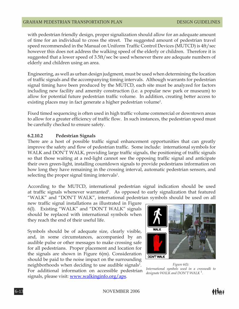
According to the MUTCD, international pedestrian signal indication should be used at traffic signals whenever warranted1. As opposed to early signalization that featured “WALK” and “DON’T WALK”, international pedestrian symbols should be used on all new traffic signal installations as illustrated in Figure 6(l). Existing “WALK” and “DON’T WALK” signals should be replaced with international symbols when they reach the end of their useful life.
Symbols should be of adequate size, clearly visible, and, in some circumstances, accompanied by an audible pulse or other messages to make crossing safe for all pedestrians. Proper placement and location for the signals are shown in Figure 6(m). Consideration should be paid to the noise impact on the surrounding neighborhoods when deciding to use audible signals1. For additional information on accessible pedestrian signals, please visit: www.walkinginfo.org/aps.
Figure 6(l):International symbols used in a crosswalk to designate WALK and DON’T WALK �.

6-�� NOVEMBER 2006
GRAHAM PEDESTRIAN TRANSPORTATION PLANDESIGN GUIDELINES
Audible cues can also be used to pulse along with a countdown signal. Countdown signals are pedestrian signals that show how many seconds the pedestrian has remaining to cross the street. The countdown can begin at the beginning of the WALK phase, perhaps flashing white or yellow, or at the beginning of the clearance, or DON’T WALK phase, flashing yellow as it counts down.
The timing of these or other pedestrian signals needs to be adapted to a given situation. There are three types of signal timing generally used: concurrent, exclusive, and leading pedestrian interval (LPI). The strengths and weaknesses of each will be discussed with an emphasis on when they are best employed.
Concurrent signal timing refers to a situation where motorists running parallel to the crosswalk are allowed to turn into and through the crosswalk, left or right, after yielding to pedestrians. This condition is not considered as safe as some of the latter options, however this type of signal crossings generally allows for more pedestrian crossing opportunities and less wait time. In addition, traffic is allowed to flow a bit more freely. Concurrent signal timing is best used where lower volume turning movements exist1.
Where there are high-volume turning situations that conflict with pedestrian movements, the exclusive pedestrian interval is the preferred solution. The exclusive pedestrian intervals stop traffic in all directions. In order to keep traffic flowing regularly, there is often a greater pedestrian wait time associated with this system. Although it has been shown that pedestrian crashes have been reduced by 50% in some commercial or downtown areas by using these intervals, the long wait times can encourage some to attempt a cross when there is a perceived lull in traffic1. These types of crossings are dangerous and may negate the use of the system. A problem is also created for those with visual impairments when the audible cues of the passing parallel traffic is eliminated. Often an audible signal will have to accompany a WALK signal1.
Figure 6(m):Location of pedestrian push-button.�
6-�� NOVEMBER 2006
GRAHAM PEDESTRIAN TRANSPORTATION PLAN DESIGN GUIDELINES
A proven enhancement that prevents many of the conflicts addressed under either of the former methods is LPI. An LPI works in conjunction with a concurrent signal timing system and simply gives the pedestrian a few seconds head start on the parallel traffic. An advance walk signal is received prior to a green light for motorists. This creates a situation where the pedestrian can better see traffic, and more importantly, the motorists can see and properly yield to pedestrians1. Long-term research has shown that this system has worked well in places like New York City (where it has been used for 20 years) at reducing motorist and pedestrian conflict1. As with the exclusive pedestrian interval, an audible cue will need to accompany the WALK signal for the visually impaired.
The use of infrared or microwave pedestrian detectors has increased in many cities worldwide. Theses devices replace the traditional push-button system. Although still experimental, they appear to be improving pedestrian signal compliance as well as reducing the number of pedestrian and vehicle conflicts1. Perhaps the best use of these devices is when they are employed to extend crossing time for slower moving pedestrians. Whether these devices are used or the traditional push-button system is employed, it is best to provide instant feedback to pedestrians regarding the length of their wait. This is thought to increase and improve pedestrian signal compliance.
Guidelines3+9: • Pedestrian signals should be placed in locations that are clearly visible to all pedestrians.• Larger pedestrian signals should be utilized on wider roadways, to ensure readability.• Pedestrian signal pushbuttons should be well-signed and visible.• Pedestrian signal pushbuttons should clearly indicate which crossing direction they control.• Pedestrian signal pushbuttons should reachable from a flat surface, at a maximum height of 3.5 feet and be located on a level landing to ensure ease of operation by pedestrians in wheelchairs. • Walk intervals should be provided during every cycle, especially in high pedestrian traffic areas.
Cost1: Traffic signals: $20,000 - $140,000 Pedestrian signals: $5,000 Adjusting signal timing requires a few hours of staff time
6.2.11 Right Turn on Red RestrictionsIntroduced in the 1970’s as a fuel saving technique, the Right Turn on Red (RTOR) law is thought to have had a detrimental effect on pedestrians1. The issue is not the law itself but rather the relaxed enforcement of certain caveats within the law such as coming to a complete stop and yielding to pedestrians. Often motorists will either nudge into a crosswalk to check for oncoming traffic without looking for pedestrians or slow, but not stop, for the red-light while making the turn.
6-�6 NOVEMBER 2006
GRAHAM PEDESTRIAN TRANSPORTATION PLANDESIGN GUIDELINES
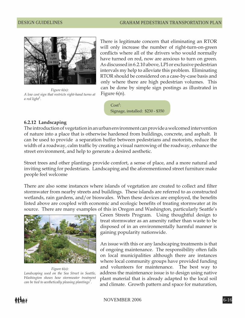
Figure 6(n):A low cost sign that restricts right-hand turns at a red light�.
Figure 6(o):Landscaping used on the Sea Street in Seattle, Washington shows how stormwater treatment can be tied to aesthetically pleasing plantings�.
There is legitimate concern that eliminating an RTOR will only increase the number of right-turn-on-green conflicts where all of the drivers who would normally have turned on red, now are anxious to turn on green. As discussed in 6.2.10 above, LPI or exclusive pedestrian intervals my help to alleviate this problem. Eliminating RTOR should be considered on a case-by-case basis and only where there are high pedestrian volumes. This can be done by simple sign postings as illustrated in Figure 6(n).
Cost1: Signage, installed: $230 - $350
6.2.12 LandscapingThe introduction of vegetation in an urban environment can provide a welcomed intervention of nature into a place that is otherwise hardened from buildings, concrete, and asphalt. It can be used to provide a separation buffer between pedestrians and motorists, reduce the width of a roadway, calm traffic by creating a visual narrowing of the roadway, enhance the street environment, and help to generate a desired aesthetic.
Street trees and other plantings provide comfort, a sense of place, and a more natural and inviting setting for pedestrians. Landscaping and the aforementioned street furniture make people feel welcome
There are also some instances where islands of vegetation are created to collect and filter stormwater from nearby streets and buildings. These islands are referred to as constructed wetlands, rain gardens, and/or bioswales. When these devices are employed, the benefits listed above are coupled with economic and ecologic benefits of treating stormwater at its source. There are many examples of this in Oregon and Washington, particularly Seattle’s
Green Streets Program. Using thoughtful design to treat stormwater as an amenity rather than waste to be disposed of in an environmentally harmful manner is gaining popularity nationwide.
An issue with this or any landscaping treatments is that of ongoing maintenance. The responsibility often falls on local municipalities although there are instances where local community groups have provided funding and volunteers for maintenance. The best way to address the maintenance issue is to design using native plant material that is already adapted to the local soil and climate. Growth pattern and space for maturation,

6-�� NOVEMBER 2006
GRAHAM PEDESTRIAN TRANSPORTATION PLAN DESIGN GUIDELINES
particularly with larger tree plantings, are important to avoid cracking sidewalks and other pedestrian obstructions.
Guidelines3: • Buffer zone plantings should be maintained at no higher than three feet to allow sight distance for motorists and pedestrians.• Trees with large canopies planted between the sidewalk and street should generally be trimmed to keep branches at least seven feet above the sidewalk. • Plants and trees should be chosen to match character of area.
Cost1: Varies greatly. May be supplemented by funds from community organizations or homeowners
associations.
6.2.13 Roadway Lighting ImprovementsProper lighting in terms of quality, placement, and sufficiency can greatly enhance a nighttime urban experience as well as create a safe environment for motorists and pedestrians. Two-thirds of all pedestrian fatalities occur during low-light conditions3. Attention should be paid to crossings so that there is sufficient ambience for motorists to see pedestrians. To be most effective, lighting should be consistent, adequately spaced, and distinguished, providing adequate light.
In most cases, roadway street lighting can be designed to illuminate the sidewalk area as well. The visibility needs of both pedestrian and motorist should be considered. In commercial or downtown areas and other areas of high pedestrian volumes, the addition of lower level, pedestrian-scale lighting to streetlights with emphasis on crossings and intersections may be employed to generate a desired ambiance. A variety of lighting choices include mercury vapor, incandescent, or less expensive high-pressure sodium lighting for pedestrian level lighting1. Roadway streetlights can range from 20-40 feet in height while pedestrian-scale lighting is typically 10-15 feet.
It is important to note that every effort should be made to address and prevent light pollution. Also known as photo pollution, light pollution is “excess or obtrusive light created by humans”4. Whenever urban improvements are made where lighting is addressed, a qualified lighting expert should be consulted early in the process. This individual should not only create a safe and attractive ambiance, but will do so with the minimum of fixtures, an awareness of the importance of minimizing photo pollution, and with a focus on minimizing future energy use. A thoughtful plan of how and where to light will reap benefits not only in potential reduced infrastructure cost, but future energy costs as well.
6-�� NOVEMBER 2006
GRAHAM PEDESTRIAN TRANSPORTATION PLANDESIGN GUIDELINES
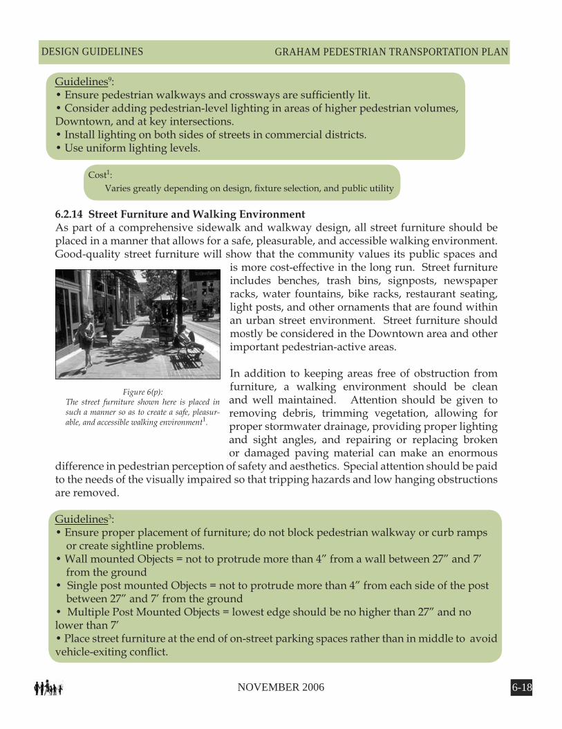
Figure 6(p):The street furniture shown here is placed in such a manner so as to create a safe, pleasur-able, and accessible walking environment�.
Guidelines9: • Ensure pedestrian walkways and crossways are sufficiently lit. • Consider adding pedestrian-level lighting in areas of higher pedestrian volumes, Downtown, and at key intersections.• Install lighting on both sides of streets in commercial districts.• Use uniform lighting levels.
Cost1: Varies greatly depending on design, fixture selection, and public utility
6.2.14 Street Furniture and Walking EnvironmentAs part of a comprehensive sidewalk and walkway design, all street furniture should be placed in a manner that allows for a safe, pleasurable, and accessible walking environment. Good-quality street furniture will show that the community values its public spaces and
is more cost-effective in the long run. Street furniture includes benches, trash bins, signposts, newspaper racks, water fountains, bike racks, restaurant seating, light posts, and other ornaments that are found within an urban street environment. Street furniture should mostly be considered in the Downtown area and other important pedestrian-active areas.
In addition to keeping areas free of obstruction from furniture, a walking environment should be clean and well maintained. Attention should be given to removing debris, trimming vegetation, allowing for proper stormwater drainage, providing proper lighting and sight angles, and repairing or replacing broken or damaged paving material can make an enormous
difference in pedestrian perception of safety and aesthetics. Special attention should be paid to the needs of the visually impaired so that tripping hazards and low hanging obstructions are removed.
Guidelines3: • Ensure proper placement of furniture; do not block pedestrian walkway or curb ramps or create sightline problems.• Wall mounted Objects = not to protrude more than 4” from a wall between 27” and 7’ from the ground• Single post mounted Objects = not to protrude more than 4” from each side of the post between 27” and 7’ from the ground• Multiple Post Mounted Objects = lowest edge should be no higher than 27” and no lower than 7’• Place street furniture at the end of on-street parking spaces rather than in middle to avoid vehicle-exiting conflict.
6-�� NOVEMBER 2006
GRAHAM PEDESTRIAN TRANSPORTATION PLAN DESIGN GUIDELINES
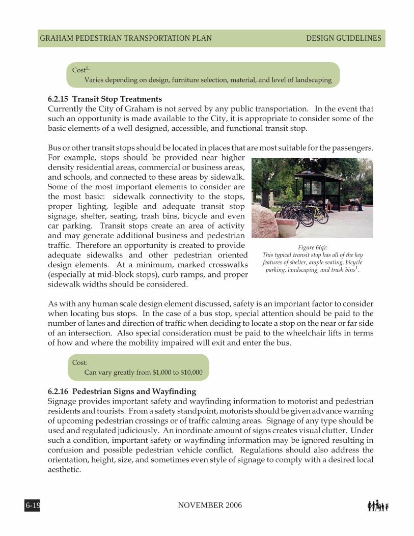
Figure 6(q):This typical transit stop has all of the key features of shelter, ample seating, bicycle parking, landscaping, and trash bins�.
Cost1: Varies depending on design, furniture selection, material, and level of landscaping
6.2.15 Transit Stop TreatmentsCurrently the City of Graham is not served by any public transportation. In the event that such an opportunity is made available to the City, it is appropriate to consider some of the basic elements of a well designed, accessible, and functional transit stop.
Bus or other transit stops should be located in places that are most suitable for the passengers. For example, stops should be provided near higher density residential areas, commercial or business areas, and schools, and connected to these areas by sidewalk. Some of the most important elements to consider are the most basic: sidewalk connectivity to the stops, proper lighting, legible and adequate transit stop signage, shelter, seating, trash bins, bicycle and even car parking. Transit stops create an area of activity and may generate additional business and pedestrian traffic. Therefore an opportunity is created to provide adequate sidewalks and other pedestrian oriented design elements. At a minimum, marked crosswalks (especially at mid-block stops), curb ramps, and proper sidewalk widths should be considered.
As with any human scale design element discussed, safety is an important factor to consider when locating bus stops. In the case of a bus stop, special attention should be paid to the number of lanes and direction of traffic when deciding to locate a stop on the near or far side of an intersection. Also special consideration must be paid to the wheelchair lifts in terms of how and where the mobility impaired will exit and enter the bus.
Cost: Can vary greatly from $1,000 to $10,000
6.2.16 PedestrianSignsandWayfindingSignage provides important safety and wayfinding information to motorist and pedestrian residents and tourists. From a safety standpoint, motorists should be given advance warning of upcoming pedestrian crossings or of traffic calming areas. Signage of any type should be used and regulated judiciously. An inordinate amount of signs creates visual clutter. Under such a condition, important safety or wayfinding information may be ignored resulting in confusion and possible pedestrian vehicle conflict. Regulations should also address the orientation, height, size, and sometimes even style of signage to comply with a desired local aesthetic.
6-20 NOVEMBER 2006
GRAHAM PEDESTRIAN TRANSPORTATION PLANDESIGN GUIDELINES
R1-5aR1-5 R9-2R9-1
R9-6R9-4
R1-6 R1-6a
W11-2S1-1 I-4
R9-4a R10-4b
R5-10b R5-10c
W15-1
R9-3a
S3-1
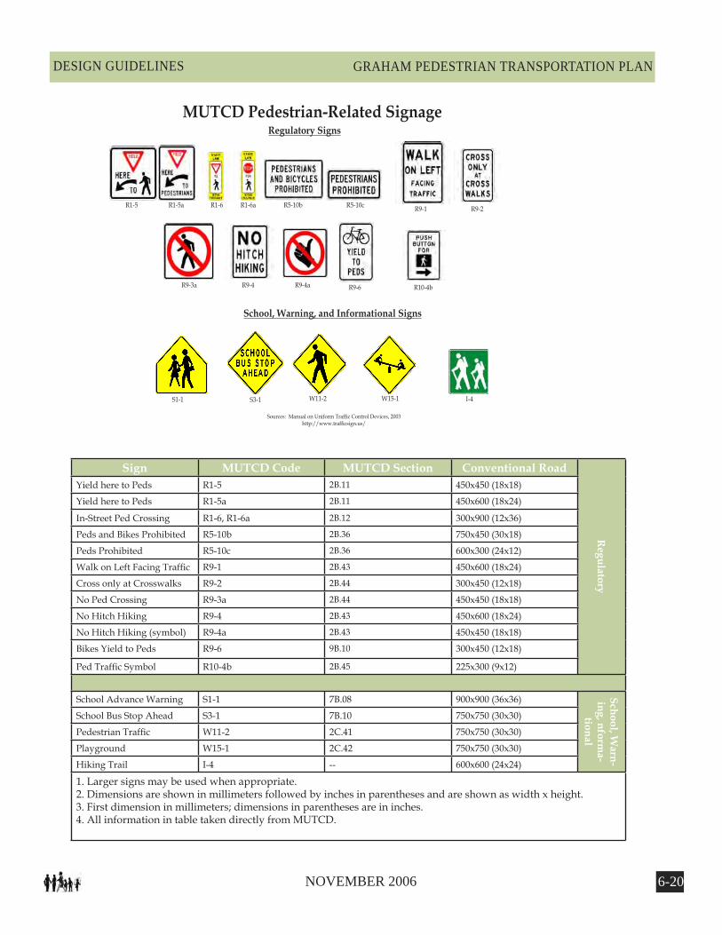
Regulatory Signs
School, Warning, and Informational Signs
MUTCD Pedestrian-Related Signage
Sources: Manual on Uniform Traffic Control Devices, 2003http://www.trafficsign.us/
Sign MUTCD Code MUTCD Section Conventional Road
Regulatory
Yield here to Peds R1-5 2B.11 450x450 (18x18)
Yield here to Peds R1-5a 2B.11 450x600 (18x24)
In-Street Ped Crossing R1-6, R1-6a 2B.12 300x900 (12x36)
Peds and Bikes Prohibited R5-10b 2B.36 750x450 (30x18)
Peds Prohibited R5-10c 2B.36 600x300 (24x12)
Walk on Left Facing Traffic R9-1 2B.43 450x600 (18x24)
Cross only at Crosswalks R9-2 2B.44 300x450 (12x18)
No Ped Crossing R9-3a 2B.44 450x450 (18x18)
No Hitch Hiking R9-4 2B.43 450x600 (18x24)
No Hitch Hiking (symbol) R9-4a 2B.43 450x450 (18x18)
Bikes Yield to Peds R9-6 9B.10 300x450 (12x18)
Ped Traffic Symbol R10-4b 2B.45 225x300 (9x12)
School Advance Warning S1-1 7B.08 900x900 (36x36) School, Warn-
ing, nforma-
tional
School Bus Stop Ahead S3-1 7B.10 750x750 (30x30)
Pedestrian Traffic W11-2 2C.41 750x750 (30x30)
Playground W15-1 2C.42 750x750 (30x30)
Hiking Trail I-4 -- 600x600 (24x24)
1. Larger signs may be used when appropriate.2. Dimensions are shown in millimeters followed by inches in parentheses and are shown as width x height.3. First dimension in millimeters; dimensions in parentheses are in inches.4. All information in table taken directly from MUTCD.
6-2� NOVEMBER 2006
GRAHAM PEDESTRIAN TRANSPORTATION PLAN DESIGN GUIDELINES
Wayfinding signage should orient and communicate in a clear, concise and functional manner. It should enhance pedestrian circulation and direct visitors and residents to important destinations. In doing so, the goal is to increase the comfort of visitors and residents while helping to convey a local identity5.
Maintenance of signage is as important as walkway maintenance. Clean, graffiti free, and relevant signage enhances guidance, recognition, and safety for pedestrians.
Cost1: Signage: $50 - $150 plus installation
6.3 BridgesProvisions should always be made to include a walking facility as a part of vehicular bridges, underpasses, or tunnels, especially if the facility is part of the Pedestrian Network. All new or replacement bridges, other than those for controlled access roadways, should accommodate pedestrians with wide sidewalks on both sides of the bridge. Even though bridge replacements do not occur regularly, it is important to consider these in longer-term pedestrian planning.
It is NCDOT bridge policy that within Urban Area boundaries, sidewalks shall be included on new bridges with curb and gutter approach roadways with no controlled access. Sidewalks should not be included on controlled access facilities. A determination on whether to provide sidewalks on one or both sides of new bridges will be made during the planning process according to the NCDOT Pedestrian Policy Guidelines. When a sidewalk is justified, it should be a minimum of five to six feet wide with a minimum handrail height of 42.”
It is also NCDOT bridge policy that bridges within the Federal-aid urban boundaries with rural-type roadway sections (shoulder approaches) may warrant special consideration. To allow for future placement of ADA acceptable sidewalks, sufficient bridge deck width should be considered on new bridges in order to accommodate the placement of sidewalks.
For more information, visit: http://www.ncdot.org/doh/construction/altern/value/manuals/RDM2001/part1/chapter6/pt1ch6.pdf&http://www.ncdot.org/doh/construction/altern/value/manuals/bpe2000.doc
Guidelines:• Sidewalks should be included on roadway bridges with no controlled access with curb and gutter approach in Urban Areas.• Sufficient bridge deck width should be considered on new bridges with rural-type shoulder approaches for future placement of sidewalks.• Sidewalk should be 5' to 6' wide.• Minimum handrail height should be 42''
6-22 NOVEMBER 2006
GRAHAM PEDESTRIAN TRANSPORTATION PLANDESIGN GUIDELINES
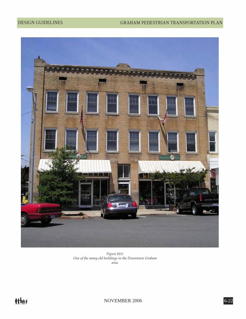
Figure 6(r):One of the many old buildings in the Downtown Graham
area.
6-2� NOVEMBER 2006
GRAHAM PEDESTRIAN TRANSPORTATION PLAN DESIGN GUIDELINES
6.4 Building Scale Cross-Sections
Context, dimension, and scale are important considerations when developing new or retrofitting existing pedestrian friendly environments. Context refers generally to the place: is it urban, rural, residential, commercial, industrial or mixed? Dimension relates to the actual size and distance of objects such as buildings. Scale relates to how both context and dimension work together within a given locality. It is often a subjective observation based on the feeling generated while occupying a space. A place that is not scaled properly will most likely feel uncomfortable, while those that are will be more pleasurable. According to the American Planning Association, some important factors within a pedestrian environment are8:
• parking configuration • building use • degree/type of non-motorist activity • truck traffic percentage • ADA requirements • location within the urban fabric • transit use
The following typical cross sections on the next four pages illustrate the interaction of these concepts:

6-2� NOVEMBER 2006
GRAHAM PEDESTRIAN TRANSPORTATION PLANDESIGN GUIDELINES
Figure 6(s):With a building ratio of 1:1, where the building heights are the same as the distance between them, a sense of enclosure is established quite easily. Depending on traffic requirements, the space can be used for tree plantings, bike lanes, wider sidewalks, or a combination of those elements�.
Figure 6(t):A building ratio of 2:1 where the building heights are half of the distance between them, requires the addition of other elements to help maintain a sense of enclosure and to reinforce the notion of human scale, and pedestrian friendly environments�.
Figure 6(u):A ratio of 3:1 approaches the maximum distance between buildings before the building edges cease to relate to each other. Any ratio larger than 4:1 starts to lose a perception of enclosure and should be avoided if at all possible�.
1:1 Ratio
2:1 Ratio
3:1 Ratio
6-2� NOVEMBER 2006
GRAHAM PEDESTRIAN TRANSPORTATION PLAN DESIGN GUIDELINES
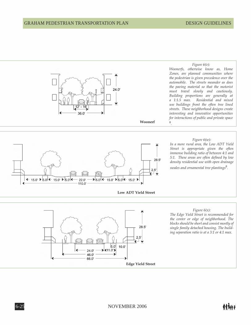
Figure 6(v):Woonerfs, otherwise know as, Home Zones, are planned communities where the pedestrian is given precedence over the automobile. The streets meander as does the paving material so that the motorist must travel slowly and cautiously. Building proportions are generally at a 1:1.5 max. Residential and mixed use buildings front the often tree lined streets. These neighborhood designs create interesting and innovative opportunities for interactions of public and private space �.
Figure 6(w):In a more rural area, the Low ADT Yield Street is appropriate given the often immense building ratio of between 4:1 and 5:1. These areas are often defined by low density residential use with open drainage swales and ornamental tree plantings�.
Figure 6(x):The Edge Yield Street is recommended for the center or edge of neighborhood. The blocks should be short and consist mostly of single family detached housing. The build-ing separation ratio is at a 3:1 or 4:1 max.
Woonerf
Low ADT Yield Street
Edge Yield Street
6-26 NOVEMBER 2006
GRAHAM PEDESTRIAN TRANSPORTATION PLANDESIGN GUIDELINES
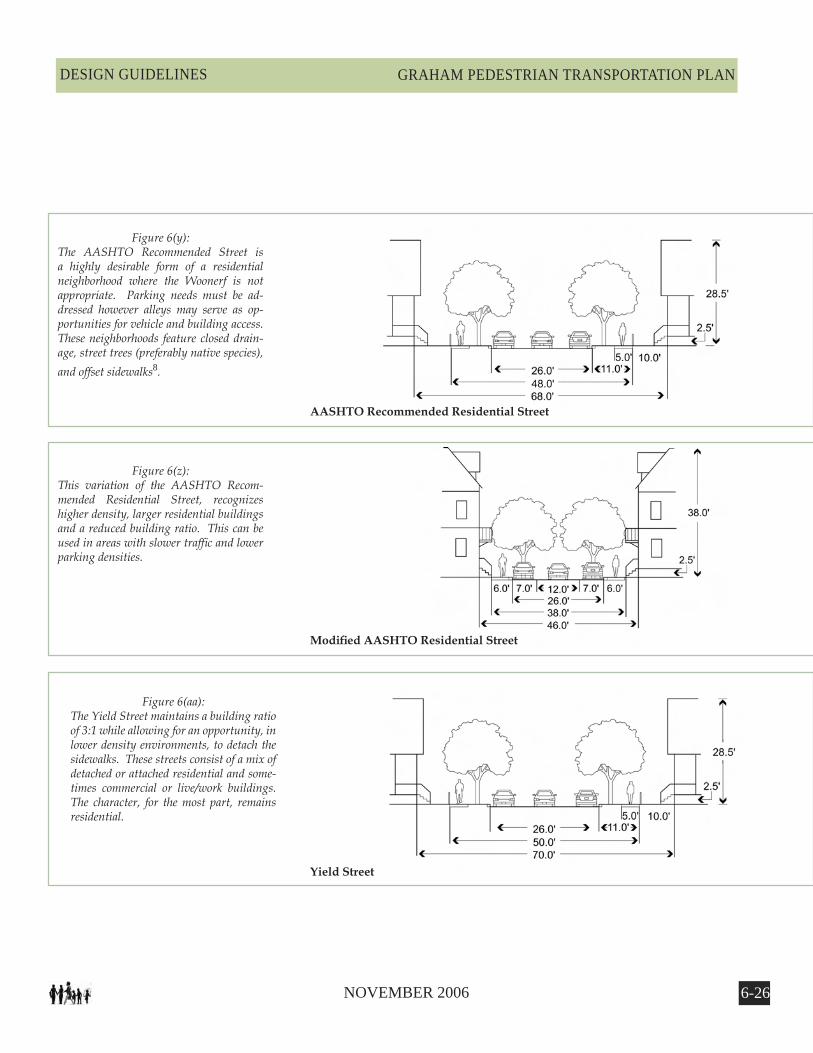
Figure 6(y):The AASHTO Recommended Street is a highly desirable form of a residential neighborhood where the Woonerf is not appropriate. Parking needs must be ad-dressed however alleys may serve as op-portunities for vehicle and building access. These neighborhoods feature closed drain-age, street trees (preferably native species), and offset sidewalks�.
Figure 6(z):This variation of the AASHTO Recom-mended Residential Street, recognizes higher density, larger residential buildings and a reduced building ratio. This can be used in areas with slower traffic and lower parking densities.
Figure 6(aa):The Yield Street maintains a building ratio of 3:1 while allowing for an opportunity, in lower density environments, to detach the sidewalks. These streets consist of a mix of detached or attached residential and some-times commercial or live/work buildings. The character, for the most part, remains residential.
AASHTO Recommended Residential Street
ModifiedAASHTOResidentialStreet
Yield Street
6-2� NOVEMBER 2006
GRAHAM PEDESTRIAN TRANSPORTATION PLAN DESIGN GUIDELINES
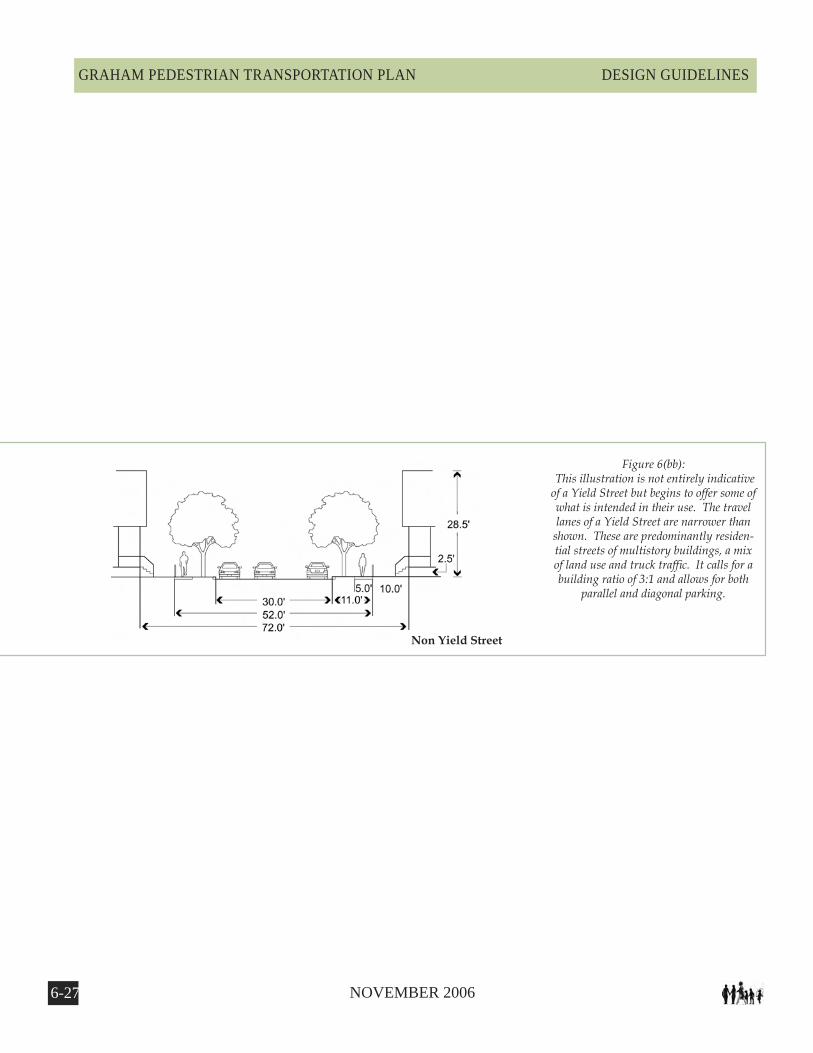
Figure 6(bb): This illustration is not entirely indicative of a Yield Street but begins to offer some of what is intended in their use. The travel lanes of a Yield Street are narrower than
shown. These are predominantly residen-tial streets of multistory buildings, a mix of land use and truck traffic. It calls for a building ratio of 3:1 and allows for both
parallel and diagonal parking.
Non Yield Street
6-2� NOVEMBER 2006
GRAHAM PEDESTRIAN TRANSPORTATION PLANDESIGN GUIDELINES
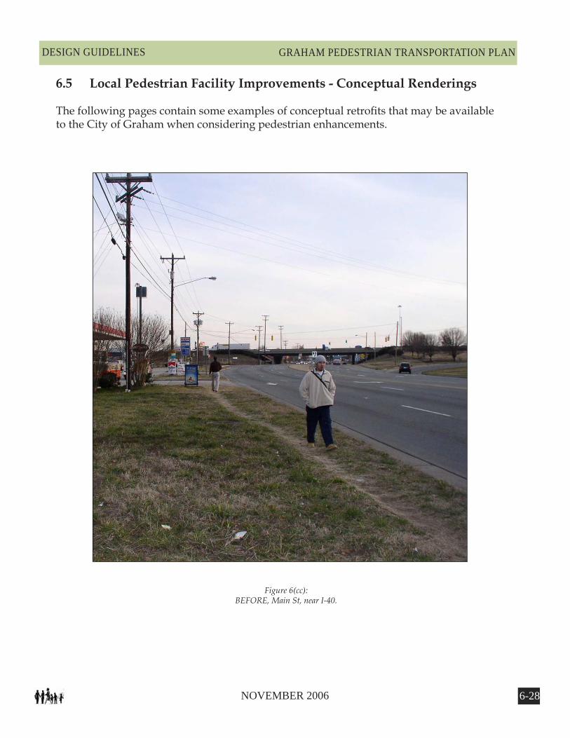
Figure 6(cc):BEFORE, Main St, near I-40.
6.5 Local Pedestrian Facility Improvements - Conceptual Renderings
The following pages contain some examples of conceptual retrofits that may be available to the City of Graham when considering pedestrian enhancements.
6-2� NOVEMBER 2006
GRAHAM PEDESTRIAN TRANSPORTATION PLAN DESIGN GUIDELINES
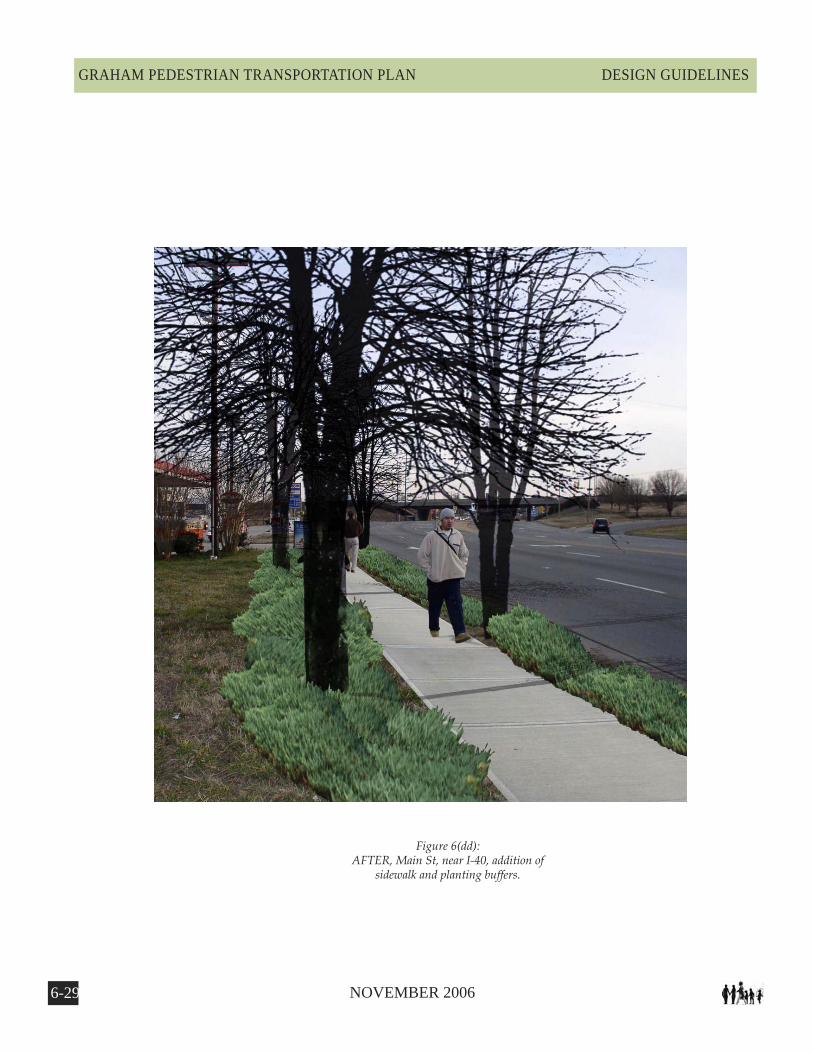
Figure 6(dd):AFTER, Main St, near I-40, addition of
sidewalk and planting buffers.

6-�0 NOVEMBER 2006
GRAHAM PEDESTRIAN TRANSPORTATION PLANDESIGN GUIDELINES
Figure 6(ee):BEFORE, Recommended greenway cor-
ridor east of Main St., near I-40

6-�� NOVEMBER 2006
GRAHAM PEDESTRIAN TRANSPORTATION PLAN DESIGN GUIDELINES
Figure 6(ff):AFTER, Recommended 10-ft, multi-use greenway corridor east of Main St., near
I-40, could provide an excellent recre-ational and transportation corridor.

6-�2 NOVEMBER 2006
GRAHAM PEDESTRIAN TRANSPORTATION PLANDESIGN GUIDELINES
Figure 6(gg):BEFORE, Intersection at City Square.
6-�� NOVEMBER 2006
GRAHAM PEDESTRIAN TRANSPORTATION PLAN DESIGN GUIDELINES
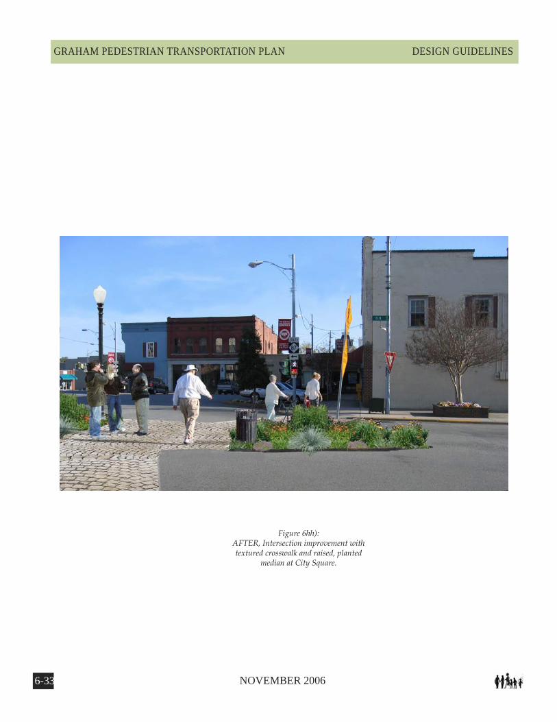
Figure 6hh):AFTER, Intersection improvement with textured crosswalk and raised, planted
median at City Square.
6-�� NOVEMBER 2006
GRAHAM PEDESTRIAN TRANSPORTATION PLANDESIGN GUIDELINES
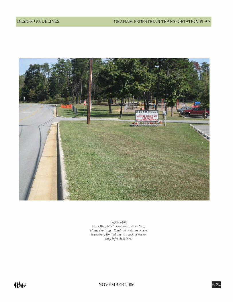
Figure 6(ii):BEFORE, North Graham Elementary,
along Trollinger Road. Pedestrian access is severely limited due to a lack of neces-
sary infrastructure.

6-�� NOVEMBER 2006
GRAHAM PEDESTRIAN TRANSPORTATION PLAN DESIGN GUIDELINES
Figure 6(jj):AFTER, A sidewalk is added to allow for pedes-trian travel. There is a paving material change at the entrance to slow traffic and notify motor-ists of the possibility of nearby pedestrians. Tree
plantings frame the vehicular and pedestrian corridors. Finally, the current grassy swale is
planted with native perennials to help filter and slow stormwater.

6-�6 NOVEMBER 2006
GRAHAM PEDESTRIAN TRANSPORTATION PLANDESIGN GUIDELINES
Figure 6(kk):BEFORE, Main Street, north of Harden.
This section of Main Street contains many interesting and architecturally significant buildings that support a thriving commer-cial core. However, the street is wide and
fast with little room for pedestrians.
6-�� NOVEMBER 2006
GRAHAM PEDESTRIAN TRANSPORTATION PLAN DESIGN GUIDELINES
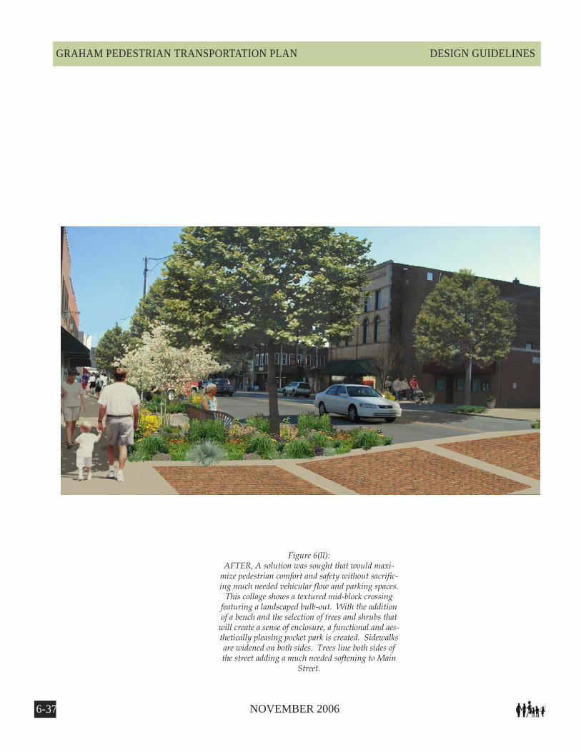
Figure 6(ll):AFTER, A solution was sought that would maxi-
mize pedestrian comfort and safety without sacrific-ing much needed vehicular flow and parking spaces.
This collage shows a textured mid-block crossing featuring a landscaped bulb-out. With the addition of a bench and the selection of trees and shrubs that
will create a sense of enclosure, a functional and aes-thetically pleasing pocket park is created. Sidewalks are widened on both sides. Trees line both sides of the street adding a much needed softening to Main
Street.
6-�� NOVEMBER 2006
GRAHAM PEDESTRIAN TRANSPORTATION PLANDESIGN GUIDELINES
(Footnotes)
1 Walkinginfo.org. [Internet]. Chapel Hill, NC: Pedestrian and Bicycle Information Center . (cited 2005 May 2). Available from http://www.walkinginfo.org/
2 Georgia Department of Transportation. (2003). Pedestrian Streetscape and Guide
3 Association of State Highway and Transportation Officials. (2004). Guide for the Planning, Design, and Operation of Pedestrian Facilities.
4 The Free Dictionary. [Internet]. Huntingdon Valley, PA: Farlex, Inc. (cited 2005 May 1). Available from http://encycl opedia.thefreedictionary.com/light%20pollution
5 City of Portland, Office of Transportation. [Internet]. Portland OR : The City of Portland. (cited 2005 May 3). Available from http://www.portlandonline.com/ transportation/?c=eafaa
6 Sefton Council. [Internet]. Sefton, UK: Sefton Council. (cited 2006 May 4) . Available from http://www.sefton.gov.uk/ images/new%20sign%20proposals.jpg
7 Seattle.gov. [Internet]. Seattle, WA: Seattle Public Utilities. (cited 2006 May 4). Available from http:// www.ci.seattle.wa.us/util/About_SPU/Drainage_&_ Sewer_System/Natural_Drainage_Systems/Street_Edge_ Alternatives/COS_004467.asp
8 American Planning Association . (2006). Planning and urban design standards. Hooken, NJ: John Wiley & Sons, Inc. 719 p.
9 USDOT Federal Highway Administration. (2002). Pedestrian Facilities Users Guide - Providing Safety and Mobility
10 San Diego Regional Planning Agency (SANDAG). (2002) Planning and Designing for Pedestrians.
11 USDOT Federal Highway Administration (2000). Roundabouts: An Informational Guide.
12 NCDOT Roadway Design Manual & NCDOT Bridge Policy