chapter 5.4 - new yorkogs.ny.gov/bu/dc/docs/word/05040electronicdocument… · web...
TRANSCRIPT

OGS Design Procedures ManualA Guide to Designing Projects for Design & Construction
Chapter 5 – Technical Documents
5.4 TECHNICAL REQUIREMENTS FOR DRAWINGS ANDELECTRONIC DOCUMENT SUBMISSIONS
A. GENERAL
1. The need to exchange information during a project’s life cycle with the State, Client and Consultants necessitates answering many questions about drawing requirements electronic media, file format, etc. The goal being to allow anyone in the organization to access, interpret and disseminate information rapidly and in a uniform manner.
2. OGS requires that all drawings be created using OGS Cadd Standards to assure that OGS can plot the drawings in-house with expected results.a. This will result in considerable time savings by not having to send
paper copies of all exchanges of information.b. Upon completion, the electronic files can be entered into our archival
process.
B. FORMAT
1. Drawings are to be prepared in compliance with OGS CAD Standards. These standards are an interpretation of the National CAD Standard. The Standard incorporates the CAD Layer Guidelines published by the American Institute of Architects, the Uniform Drawing System published by the Construction Specifications Institute, and the Tri-Service Plotting Guidelines published by the Tri-Service CADD/GIS Technology Center and U.S. Coast Guard.
2. Deliver vector, raster and vector/raster hybrid digital files in a format that is directly compatible with OGS’s Plotting Software:a. Autodesk’s AutoCAD 2013 file formatb. Bentley Microstation J or Version 8.X. file format c. Raster files in .tif or .jpg format.d. Portable Document Files (pdf) (reserved)
3. Drawings are to be prepared using OGS File Structure and Naming Standards.
4. Building Information Model (BIM) (reserved).
Revised Date 05/04/2018Chapter 5 - Technical Documents5.4 Technical Requirements for
Drawings and Electronic Document Submission
Page 1

OGS Design Procedures ManualA Guide to Designing Projects for Design & Construction
C. DELIVERY MEDIA
1. At project completion, in addition to required mylars, digital data sets should be furnished via compact disc-read only memory CD-ROM (ISO 9660 format). For exceptions, contact the OGS Team Leader.
2. All media must be compatible with the Microsoft Windows operating system. When submitting digital media, an external label should contain, at a minimum, the following information:a. Format and version of the operating system on which the media was
created (e.g., Windows 10).b. Utility (command) used for writing the files to disk.c. Sequence number for multiple CD’s, etc.d. A short description of contents including the OGS project number
and title.e. A digital index file containing a list of files and a brief description of
each file that is included on the digital media.
3. A transmittal sheet shall accompany the media containing, at a minimum, the following information:a. Information included on the external label of each CD; total number
of CD’s being delivered; a list of the file names and file descriptions on each CD.
b. Certification that all delivery media is free of known computer viruses, including the name and version of the virus scanning software used, and the date the virus scan was performed.
4. Before placing files on the delivery digital media, perform the following:a. Remove all extraneous graphics outside the border area of each
sheet, and set the active parameters to a standard setting or those in the seed/prototype file.
b. Attach all reference (external reference) files without device or directory specifications.
c. Remove plotting device references from each sheet.d. Remove all unused level/layers, reference/xref drawings, block/cell
library, styles, and data definitions from each sheet.e. Include all graphic and non-graphic files necessary to plot each
complete sheet.f. If necessary, files are only to be compressed using standard
Windows compatible utilities. Include a copy of the utility on the CD.
D. MODEL FILES AND SHEET FILES
1. Two distinct types of CADD files are addressed in this standard: model files and sheet files.a. A model file contains the physical components of a building or survey
(e.g., columns, walls, windows, ductwork, piping, etc.). Model files
Revised Date 05/04/2018Chapter 5 - Technical Documents5.4 Technical Requirements for
Drawings and Electronic Document Submission
Page 2

OGS Design Procedures ManualA Guide to Designing Projects for Design & Construction
are drawn at full scale and typically represent plans, elevations, sections, etc.
b. A sheet file is synonymous with a plotted CADD drawing file. A sheet file is a selected view or portion of the model file(s) within a border sheet. Whether the border is scaled up or the information is scaled down a sheet file is a “ready-to-plot” CADD file. There should be no information outside the border limits to allow for plotting by extents or fit elements.
2. The Figure below illustrates how different model files are referenced to a sheet file (notice that the border sheet is always a referenced model file). A sheet file is the combination of referenced model files with sheet-specific text & symbols to create a final “ready-to-plot” CADD file. A useful American Institute of Architects (AlA) rule of thumb states: “Model files are always referenced by other files, while sheet files are never referenced by other files.
3. Model files represent full-size drawings of building elements, systems, or information (e.g., the mechanical HVAC system, the architectural floor plan, details, building sections). Sheet files represent final plotted sheets. Model files are used as components in creating plotted sheet files. The information contained within a model file for a discipline may be referenced by other disciplines to create the particular model files or sheet files for that discipline.
4. A model file can be considered a “work in progress.” For instance, a mechanical engineer may reference the architect’s floor plan model file to begin development of the HVAC ductwork layout model file. Meanwhile, the architect can continue developing the floor plan to meet new requirements. Any changes to the floor plan would be immediately accessible to the mechanical engineer. The viewing of real-time updates eliminates a great deal of frustration for other disciplines because it allows for on-the-spot rather than after-the-fact modifications.
Revised Date 05/04/2018Chapter 5 - Technical Documents5.4 Technical Requirements for
Drawings and Electronic Document Submission
Page 3

OGS Design Procedures ManualA Guide to Designing Projects for Design & Construction
E. ELECTRONIC DRAWING FILE NAMING CONVENTIONS
1. Naming conventions for electronic drawing files (both model files and sheet files) allow CADD users to determine the contents of a drawing without actually displaying the file. They also provide a convenient and clear structure for organizing drawing files within project directories.
F. MODEL FILE NAMING CONVENTION
1. The model file naming convention (Figure 2) has four fields. The first field is optional for all trades except V, B, C and L. The following three fields are mandatory. The fields must appear in the correct sequence.
a. The optional first field is the 5 digit OGS Project Number. The use of Project Numbers in file names is highly recommended, because it prevents the same file name from existing in different directories.
Revised Date 05/04/2018Chapter 5 - Technical Documents5.4 Technical Requirements for
Drawings and Electronic Document Submission
Page 4
Figure 2 - Model File Naming Convention
Figure 1 - Sheet P-101

OGS Design Procedures ManualA Guide to Designing Projects for Design & Construction
b. The next field is the Discipline Designator. Table 1 lists allowable characters. For most disciplines, this field is the discipline letter and a hyphen.
c. The next field is the Model File Type (see Table 2).d. The final four-character field is user-definable.
2. Example: The model file name for an OGS project with a project number of S4444, 1st floor, Architectural Floor Plan could be S4444A-FPF1.dwg where S4444 is the Project Number, A- is the Discipline Designator, FP is the Model File Type (Floor Plan), and F1 is a user-definable set of characters for Floor 1.
3. Existing/Demolition model file naming. There are instances when a facility is being renovated and the as-built designs need to be revised to show demolition and new items.
4. A new model file type, Existing/Demolition XD (Which is not in NCS 2.0), has been added to the standard to allow users to make revisions to as-built files. This model file type is used to aid users in separating existing to remain items from items that will be demolished.
Table 1 – MODEL FILE Discipline Designators With Level 2 Designators
Discipline Designator Description Content
General G- All General All or any portion of the General Description
GI General Information General Information - Title Sheet
Hazardous Materials H- All Hazardous All or any portion of the Hazardous Discipline
Survey MappingVA Aerial Survey
VF Field Survey
Geotechnical B- All Geotechnical All or any portion of the Geotechnical Discipline
Civil C- All Civil All or any portion of the Civil Discipline
CD Civil Demolition Structure removal and site cleaning
CG Civil Grading Excavation, grading, drainage, erosion control
Civil Paving Roads, driveways, parking lots
Revised Date 05/04/2018Chapter 5 - Technical Documents5.4 Technical Requirements for
Drawings and Electronic Document Submission
Page 5

OGS Design Procedures ManualA Guide to Designing Projects for Design & Construction
CU Civil Utilities Water, sanitary sewer, storm sewer, natural gas; coordination elements for power, communications, fiber optic, telephone, cable television, and steam systems
Landscape L- All Landscape All or any portion of the Landscape Discipline
Structural S- All Structural All or any portion of the Structural Discipline
Architectural A- All Architectural All or any portion of the Architectural Discipline
Interiors I- All Interiors All or any portion of the Interiors Discipline
Equipment Q- All Equipment All or any portion of the Equipment Discipline
Fire Protection F- All Fire Protection All or any portion of the Fire Protection Discipline
Plumbing P- All Plumbing All or any portion of the Plumbing Discipline
Process D- All Process All or any portion of the Process Discipline
Mechanical M- All Mechanical All or any portion of the Mechanical Discipline
Electrical E- All Electrical All or any portion of the Electrical Discipline
Telecommunications
T- All Telecommunications
All or any portion of the Telecommunications Discipline
Resource R- All Resource All or any portion of the Resource Discipline
Revised Date 05/04/2018Chapter 5 - Technical Documents5.4 Technical Requirements for
Drawings and Electronic Document Submission
Page 6

OGS Design Procedures ManualA Guide to Designing Projects for Design & Construction
Table 2 - Model File Types
Discipline Code Definition Discipline Code Definition
General BS Border Sheet Interiors 3D Isometric/3D
KP Keyplan DT Detail
Survey/Mapping SP Survey and Mapping Plan EL Elevation
Geotechnical BL Boring Location Plan QP Equipment Plan
Civil EC Erosion Control Plan RP Furniture Plan
GP Grading Plan SC Section
KP Layout Plan SH Schedule
PL Project Location Plan SP Signage Placement Plan
PR Profiles WP System/Prewired Workstation Plan
SP Site Plan XD Existing/Demolition Plan
XD Demolition/Removals Plan Fire Protection
DT Detail
Landscape LP Landscape Planting Plan FA Fire/Alarm/Detection Plan
Structural 3D Isometric/3D FP Fire Suppression Plan
CP Column Plan LP Life Safety Plan
DT Detail SH Schedule
EL Elevation XD Existing/Demolition Plan
FP Framing Plan Plumbing DT Detail
NB Non-Building Structures Plan EL Elevation
NP Foundation Plan PP Piping Plan
SC Section XD Existing/Demolition Plan
SH Schedules Mechanical 3D Isometric/3D
XD Existing/Demolition Plan DT Detail
Architectural 3D Isometric/3D EL Elevation
CP Reflected Ceiling Plan HP HVAC Plan
DT Detail HT HTCW Plan
EL Elevation PP Piping Plan
FP Floor Plan SC Section
RP Roof Plan SH Schedules
SC Section XD Existing/Demolition Plan
SH Schedules Electrical DT Detail
XD Existing/Demolition Plan LL Lighting Plan
PP Power Plan
QP Security Equipment Plan
SH Schedules
XD Existing/Demolition PlanTelecom DT Detail
SH Schedule
Revised Date 05/04/2018Chapter 5 - Technical Documents5.4 Technical Requirements for
Drawings and Electronic Document Submission
Page 7

OGS Design Procedures ManualA Guide to Designing Projects for Design & Construction
TP Telephone/Data Plan
XD Existing/Demolition Plan
G. SHEET FILE NAMING CONVENTION
1. The sheet file naming convention (Figure 3) has one optional field (not shown), followed by three mandatory fields. Similar to the format for model file naming, the fields must be used in the correct sequence.a. The first field is the 5 digit OGS Project Number. It is optional for all
trades except V, B, C and L.b. The Sheet Discipline Designator listed in Table 3c. The Sheet Type Designator listed in Table 4d. A two-character Sheet Sequence Number (01-99)
Revised Date 05/04/2018Chapter 5 - Technical Documents5.4 Technical Requirements for
Drawings and Electronic Document Submission
Page 8
Figure 3 – Sheet File Naming Convention

OGS Design Procedures ManualA Guide to Designing Projects for Design & Construction
Table 3 - Sheet Discipline Designator Table 4 - Sheet Type Designator
General G General (symbols, legend, notes, etc.) 0Hazardous Materials H Plans (horizontal views) 1
Survey/Mapping V Elevations (vertical views) 2
Geotechnical B Sections (sectional views) 3
Civil Works W Large Scale Views (plans, elevations, or sections that are not details) 4
Civil C Details 5
Landscape L Schedules and Diagrams 6
Structural S User Defined 7
Architectural A User Defined 8
Interiors I 3D Representations (Isometrics, perspectives, photographs) 9
Equipment Q
Fire Protection F
Plumbing P
Process D
Mechanical M
Electrical E
Telecommunications T
Resource R
Other Disciplines X
Contractor/Shop Drawings Z
Operations O
H. COORDINATION BETWEEN SHEET FILE NAME AND SHEET IDENTIFIER
1. The sheet identifier (for use in the sheet identification block, reference bubbles, etc.) is to consist of the discipline designator, sheet file designator, and the sheet sequence number. Coordinate the sheet identifier with the name assigned to the electronic sheet file.
I. GRAPHIC CONCEPTS
1. Presentation Graphics: The first step in establishing an effective CADD standard is the development of a uniform approach to presentation graphics. Presentation graphics typically consist of drawing elements such as lines, arcs, shapes, text, and their attributes (line color, line width, and line style).
2. Line Widths: The use of varied line widths on AEC drawings substantially improves the readability of the documents. For all projects prepared for OGS there are nine (9) allowable line widths.
Revised Date 05/04/2018Chapter 5 - Technical Documents5.4 Technical Requirements for
Drawings and Electronic Document Submission
Page 9

OGS Design Procedures ManualA Guide to Designing Projects for Design & Construction
a. (0.13 mm) Extra Fine lines are to be used sparingly, mostly for poche/patterning.
b. (0.18 mm) Fine lines are to be used for detail on plans, Windows, ‘Equipment (Not In Contract)’ or to lighten backgrounds.
c. (0.25 mm) Thin lines are to be used for depicting dimension lines, dimension leader/witness lines, note leader lines, line terminators (arrowheads, dots, slashes), phantom lines, hidden lines, center lines, long break lines, schedule grid lines, and object lines seen at a distance.
d. (0.35 mm) Medium lines are to be used for depicting minor object lines, dimension text, text for notes/callouts, and schedule text.
e. (0.50 mm) Wide lines are to be used for major object lines, cut lines, section cutting plane lines, and titles.
f. (0.70 mm) Extra wide lines are to be used for minor title underlining, schedule outlines, large titles, and object lines requiring special emphasis. For very large scale details drawn at 3 in. = 1 ft-0 in. or larger, the extra wide width should be used for the object lines. Extra wide widths are also appropriate for use as an elevation grade line, building footprint, or top of grade lines on section/foundation details.
g. (1.00 mm) This line width is to be used for major title underlining and separating portions of drawings
h. (1.40 mm) This line width is to be used for border sheet outlines and cover sheet line work and as an option for the designer as required.
i. (2.00 mm) This line width is an option for the designer as required.
Revised Date 05/04/2018Chapter 5 - Technical Documents5.4 Technical Requirements for
Drawings and Electronic Document Submission
Page 10

OGS Design Procedures ManualA Guide to Designing Projects for Design & Construction
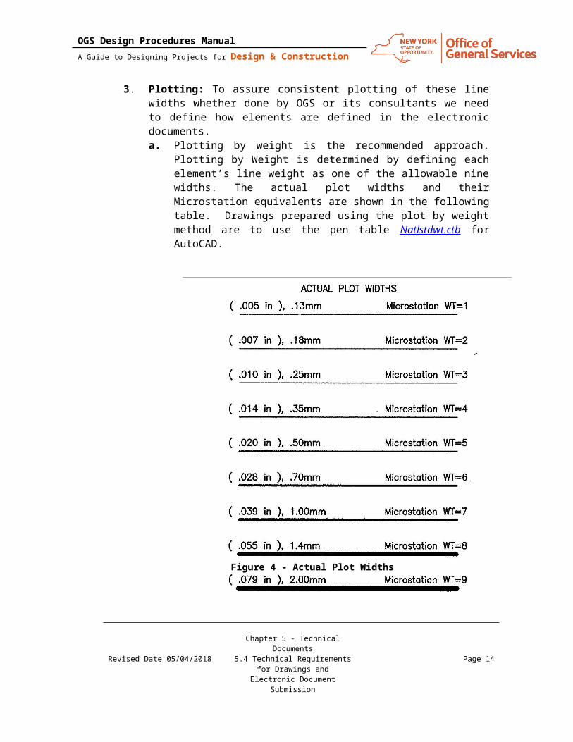
3. Plotting: To assure consistent plotting of these line widths whether done by OGS or its consultants we need to define how elements are defined in the electronic documents.a. Plotting by weight is the recommended approach. Plotting by Weight
is determined by defining each element’s line weight as one of the allowable nine widths. The actual plot widths and their Microstation equivalents are shown in the following table. Drawings prepared using the plot by weight method are to use the pen table Natlstdwt.ctb for AutoCAD.
b. Plotting by color is allowed as AutoCAD Release 14 and earlier did not allow for plotting by weight. The table below (Figure 5) defines the color to weight method. Drawings prepared using the plot by color method are to use the pen table Natlstd.ctb for AutoCAD.
Revised Date 05/04/2018Chapter 5 - Technical Documents5.4 Technical Requirements for
Drawings and Electronic Document Submission
Page 11
Figure 4 - Actual Plot Widths

OGS Design Procedures ManualA Guide to Designing Projects for Design & Construction
4. Line Types/Styles: The line types used should match those shown on the Symbols and Abbreviation sheets. (A-001) Any use of user-defined custom line styles must be coordinated with OGS.
5. Line Color: The primary reason to use color in CADD drawings is to improve the clarity of the drawing on a computer monitor. When plotting by
Revised Date 05/04/2018Chapter 5 - Technical Documents5.4 Technical Requirements for
Drawings and Electronic Document Submission
Page 12
Figure 5 - Color to Weight (inches)

OGS Design Procedures ManualA Guide to Designing Projects for Design & Construction
element weight color has no effect except for screening. If plotting by color you must follow the color to weight table (Figure 5).
J. SCREENING
1. Screened images are created through a process in which the density and pattern of black and white dots are varied to simulate different shades of gray. Varying the intensity of gray scales allows users to distinguish different aspects of a drawing when it is plotted. For example, an area on a site designated for demolition can be assigned a color that has been assigned a screening percentage. When plotted, the area will be shown at a lighter shade compared with other elements in the drawing. This will allow the contractor to immediately identify the demolition area on the drawing.
2. Use the following colors and percentages for screening:a. If you plot by color using NatlStd.ctb then you have 2 shades. Colors
50 through 59 will give you a 20% screen for the 9 line weights and colors 170 through 179 will give you a 50% screen for the 9 line weights.
b. If you plot by weight using NatlStdWt.ctb then you have 5 shades available for your use.
Color 10 is a 10% screen.Color 50 is a 20% screenColor 90 is a 30% screenColor 130 is a 40% screenColor 170 is a 50% screen
K. TEXT STYLES/FONTS
1. Contrasting text styles (or fonts) are used within a drawing to delineate types of information. For most A/E/C drawings, the five fonts shown should be sufficient.
Revised Date 05/04/2018Chapter 5 - Technical Documents5.4 Technical Requirements for
Drawings and Electronic Document Submission
Page 13
OGS Design Procedures ManualA Guide to Designing Projects for Design & Construction
Figure 6 - AutoCAD Text Style / Microstation Font
2. The minimum text size is 3.2 mm (1/8") for hand drafting and 2.5 mm (3/32") for CADD drawings.
L. BORDER SHEETS
1. A border sheet model file contains border sheet line work, the title block, and project-specific symbols and text. Project information is added to the border using the block ProjInfo. Typically, each discipline will reference the same border sheet for each project.
2. Sheet-specific information is added to the title block in the plot sheet using the appropriate attributed blocks (Table 5) prior to printing the final sheet file.
Revised Date 05/04/2018Chapter 5 - Technical Documents5.4 Technical Requirements for
Drawings and Electronic Document Submission
Page 14

OGS Design Procedures ManualA Guide to Designing Projects for Design & Construction
Revised Date 05/04/2018Chapter 5 - Technical Documents5.4 Technical Requirements for
Drawings and Electronic Document Submission
Page 15
Figure 7 – Border Sheet Title Block

OGS Design Procedures ManualA Guide to Designing Projects for Design & Construction
3. In the lower left corner of each border sheet is a plot size label. This is not to be deleted. If permission is granted to use a non-standard sheet, modify the label to reflect the actual plotted sheet size.
M. LEVEL/LAYER ASSIGNMENTS
1. CADD levels or layers are analogous to overlays in manual drafting systems and serve to separate graphic elements (lines, shapes, and text) according to the design discipline they represent.
2. The types of information represented by individual levels/layers can be grouped into two primary types: model-specific information and sheet-specific information.a. Model-specific information represents the physical form of a site, a
building, or objects composing a building. This information is often shared between drawings. Examples include walls, doors, light fixtures, and room numbers. Model-specific information may be either literal (e.g., walls) or symbolic (e.g., electrical outlets).
b. Sheet-specific information may include notes, annotative symbols, and titles. This type of information is usually not shared between drawings.
3. To use and manipulate model-specific and sheet-specific information effectively, every level/layer must be defined (standardized) by its name and its use.
N. LEVEL/LAYER NAMING CONVENTION
1. The reuse, not duplication, of graphic information reduces drawing time and improves project coordination. The level/layer is the basic tool used in CADD for managing graphic information. The levels/layers defined within these standards are based on the recommendations set forth in “AlA CAD Layer Guidelines” (MA 2001).
2. Level/layer names consist of a two-character Discipline Designator (e.g., “A-” for Architectural, “M-” for Mechanical), followed by a four-character Major Group (e.g., “DOOR” for Doors, “LITE” for Lighting Fixtures), followed by four-character Minor Group (e.g., A-WALL-FULL-EXTR for exterior full height walls versus A-WALL-FULL-INTR for interior full height walls).
Revised Date 05/04/2018Chapter 5 - Technical Documents5.4 Technical Requirements for
Drawings and Electronic Document Submission
Page 16
Table 5 - Sheet Blocks
Drawing Size Sheet Information Submission Date Revision Date36x24 SheetInfo SubmissionDate RevisionDate17x11 SheetInfoB SubmissionDateB RevisionDateB8.5x11 SheetInfoA -- RevisionDateA

OGS Design Procedures ManualA Guide to Designing Projects for Design & Construction
O. DEMOLITION LEVELS/LAYERS
1. Users should note that several model files have three levels/layers reserved for demolition items. These levels/ layers are as follows with ** representing a Discipline. These levels/layers should only be used when an Existing/Demolition model file is being created. For instance, the architect or engineer will sometimes have existing as-built model files, such as Site Plans and Floor Plans from a previous project. A copy of the as-built file will be made for use in the current project. This copy is renamed to be the Existing/ Demolition Plan model file for that discipline. In order to distinguish items to be demolished from existing items that will remain, those items should be moved to the Demolition levels/layers. When the Existing/Demolition Plan model file is referenced into a new file to create the New construction items, the Demolition levels/layers would be turned off.
P. REFERENCE FILES (XREFS)
1. Reference files (external references or XREFs) enable designers to share drawing information electronically, eliminating the need to exchange hard copy drawings between the design disciplines. With the use of reference files, the structural engineer need not wait for the architect to complete the architectural floor plans before beginning the structural framing plan model file. Nor does the engineer have to redraw the architect’s structural walls on the structural framing plan model file.
2. Referencing electronic drawing information makes any future changes made by the architect apparent to the structural designer. This real-time access to the work of others ensures accuracy and consistency within a set of drawings and helps promote concurrent design efforts. No longer does one discipline have to wait until another discipline is nearly finished before they begin their drawings.
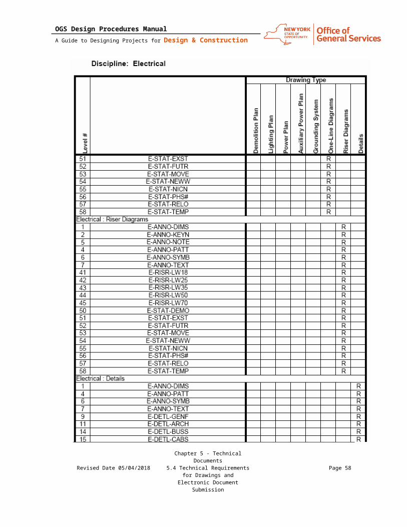
3. The use of reference files is a key component in the successful use of the level/layer assignments. To create either a model file or a final sheet file, multiple referenced model files may be required. The following tables should provide information on typical layer/level names as well as the relationship of the model files to each other to create individual sheet file.
Revised Date 05/04/2018Chapter 5 - Technical Documents5.4 Technical Requirements for
Drawings and Electronic Document Submission
Page 17

OGS Design Procedures ManualA Guide to Designing Projects for Design & Construction
Q. MODEL/SHEET FILE LAYER/LEVEL ASSIGNMENT AND DRAWING RELATIONSHIP TABLES
Revision History:
Rev Date Description Reviewed by:
Approved by:
0 02/14/11 Last revised date
1 05/04/18Functional review, minor revisions, updated CAD version and file types
Malary Dostie
Revised Date 05/04/2018Chapter 5 - Technical Documents5.4 Technical Requirements for
Drawings and Electronic Document Submission
Page 18

OGS Design Procedures ManualA Guide to Designing Projects for Design & Construction
Revised Date 05/04/2018Chapter 5 - Technical Documents5.4 Technical Requirements for
Drawings and Electronic Document Submission
Page 19

OGS Design Procedures ManualA Guide to Designing Projects for Design & Construction
Revised Date 05/04/2018Chapter 5 - Technical Documents5.4 Technical Requirements for
Drawings and Electronic Document Submission
Page 20

OGS Design Procedures ManualA Guide to Designing Projects for Design & Construction
Revised Date 05/04/2018Chapter 5 - Technical Documents5.4 Technical Requirements for
Drawings and Electronic Document Submission
Page 21

OGS Design Procedures ManualA Guide to Designing Projects for Design & Construction
Revised Date 05/04/2018Chapter 5 - Technical Documents5.4 Technical Requirements for
Drawings and Electronic Document Submission
Page 22

OGS Design Procedures ManualA Guide to Designing Projects for Design & Construction
Revised Date 05/04/2018Chapter 5 - Technical Documents5.4 Technical Requirements for
Drawings and Electronic Document Submission
Page 23

OGS Design Procedures ManualA Guide to Designing Projects for Design & Construction
Revised Date 05/04/2018Chapter 5 - Technical Documents5.4 Technical Requirements for
Drawings and Electronic Document Submission
Page 24

OGS Design Procedures ManualA Guide to Designing Projects for Design & Construction
Revised Date 05/04/2018Chapter 5 - Technical Documents5.4 Technical Requirements for
Drawings and Electronic Document Submission
Page 25

OGS Design Procedures ManualA Guide to Designing Projects for Design & Construction
Revised Date 05/04/2018Chapter 5 - Technical Documents5.4 Technical Requirements for
Drawings and Electronic Document Submission
Page 26

OGS Design Procedures ManualA Guide to Designing Projects for Design & Construction
Revised Date 05/04/2018Chapter 5 - Technical Documents5.4 Technical Requirements for
Drawings and Electronic Document Submission
Page 27

OGS Design Procedures ManualA Guide to Designing Projects for Design & Construction
Revised Date 05/04/2018Chapter 5 - Technical Documents5.4 Technical Requirements for
Drawings and Electronic Document Submission
Page 28

OGS Design Procedures ManualA Guide to Designing Projects for Design & Construction
Revised Date 05/04/2018Chapter 5 - Technical Documents5.4 Technical Requirements for
Drawings and Electronic Document Submission
Page 29

OGS Design Procedures ManualA Guide to Designing Projects for Design & Construction
Revised Date 05/04/2018Chapter 5 - Technical Documents5.4 Technical Requirements for
Drawings and Electronic Document Submission
Page 30

OGS Design Procedures ManualA Guide to Designing Projects for Design & Construction
Revised Date 05/04/2018Chapter 5 - Technical Documents5.4 Technical Requirements for
Drawings and Electronic Document Submission
Page 31

OGS Design Procedures ManualA Guide to Designing Projects for Design & Construction
Revised Date 05/04/2018Chapter 5 - Technical Documents5.4 Technical Requirements for
Drawings and Electronic Document Submission
Page 32

OGS Design Procedures ManualA Guide to Designing Projects for Design & Construction
Revised Date 05/04/2018Chapter 5 - Technical Documents5.4 Technical Requirements for
Drawings and Electronic Document Submission
Page 33

OGS Design Procedures ManualA Guide to Designing Projects for Design & Construction
Revised Date 05/04/2018Chapter 5 - Technical Documents5.4 Technical Requirements for
Drawings and Electronic Document Submission
Page 34

OGS Design Procedures ManualA Guide to Designing Projects for Design & Construction
Revised Date 05/04/2018Chapter 5 - Technical Documents5.4 Technical Requirements for
Drawings and Electronic Document Submission
Page 35

OGS Design Procedures ManualA Guide to Designing Projects for Design & Construction
Revised Date 05/04/2018Chapter 5 - Technical Documents5.4 Technical Requirements for
Drawings and Electronic Document Submission
Page 36

OGS Design Procedures ManualA Guide to Designing Projects for Design & Construction
Revised Date 05/04/2018Chapter 5 - Technical Documents5.4 Technical Requirements for
Drawings and Electronic Document Submission
Page 37

OGS Design Procedures ManualA Guide to Designing Projects for Design & Construction
Revised Date 05/04/2018Chapter 5 - Technical Documents5.4 Technical Requirements for
Drawings and Electronic Document Submission
Page 38

OGS Design Procedures ManualA Guide to Designing Projects for Design & Construction
Revised Date 05/04/2018Chapter 5 - Technical Documents5.4 Technical Requirements for
Drawings and Electronic Document Submission
Page 39

OGS Design Procedures ManualA Guide to Designing Projects for Design & Construction
Revised Date 05/04/2018Chapter 5 - Technical Documents5.4 Technical Requirements for
Drawings and Electronic Document Submission
Page 40

OGS Design Procedures ManualA Guide to Designing Projects for Design & Construction
Revised Date 05/04/2018Chapter 5 - Technical Documents5.4 Technical Requirements for
Drawings and Electronic Document Submission
Page 41

OGS Design Procedures ManualA Guide to Designing Projects for Design & Construction
Revised Date 05/04/2018Chapter 5 - Technical Documents5.4 Technical Requirements for
Drawings and Electronic Document Submission
Page 42

OGS Design Procedures ManualA Guide to Designing Projects for Design & Construction
Revised Date 05/04/2018Chapter 5 - Technical Documents5.4 Technical Requirements for
Drawings and Electronic Document Submission
Page 43

OGS Design Procedures ManualA Guide to Designing Projects for Design & Construction
Revised Date 05/04/2018Chapter 5 - Technical Documents5.4 Technical Requirements for
Drawings and Electronic Document Submission
Page 44

OGS Design Procedures ManualA Guide to Designing Projects for Design & Construction
Revised Date 05/04/2018Chapter 5 - Technical Documents5.4 Technical Requirements for
Drawings and Electronic Document Submission
Page 45

OGS Design Procedures ManualA Guide to Designing Projects for Design & Construction
Revised Date 05/04/2018Chapter 5 - Technical Documents5.4 Technical Requirements for
Drawings and Electronic Document Submission
Page 46

OGS Design Procedures ManualA Guide to Designing Projects for Design & Construction
Revised Date 05/04/2018Chapter 5 - Technical Documents5.4 Technical Requirements for
Drawings and Electronic Document Submission
Page 47

OGS Design Procedures ManualA Guide to Designing Projects for Design & Construction
Revised Date 05/04/2018Chapter 5 - Technical Documents5.4 Technical Requirements for
Drawings and Electronic Document Submission
Page 48

OGS Design Procedures ManualA Guide to Designing Projects for Design & Construction
Revised Date 05/04/2018Chapter 5 - Technical Documents5.4 Technical Requirements for
Drawings and Electronic Document Submission
Page 49

OGS Design Procedures ManualA Guide to Designing Projects for Design & Construction
Revised Date 05/04/2018Chapter 5 - Technical Documents5.4 Technical Requirements for
Drawings and Electronic Document Submission
Page 50

OGS Design Procedures ManualA Guide to Designing Projects for Design & Construction
Revised Date 05/04/2018Chapter 5 - Technical Documents5.4 Technical Requirements for
Drawings and Electronic Document Submission
Page 51

OGS Design Procedures ManualA Guide to Designing Projects for Design & Construction
Revised Date 05/04/2018Chapter 5 - Technical Documents5.4 Technical Requirements for
Drawings and Electronic Document Submission
Page 52

OGS Design Procedures ManualA Guide to Designing Projects for Design & Construction
Revised Date 05/04/2018Chapter 5 - Technical Documents5.4 Technical Requirements for
Drawings and Electronic Document Submission
Page 53

OGS Design Procedures ManualA Guide to Designing Projects for Design & Construction
Revised Date 05/04/2018Chapter 5 - Technical Documents5.4 Technical Requirements for
Drawings and Electronic Document Submission
Page 54

OGS Design Procedures ManualA Guide to Designing Projects for Design & Construction
Revised Date 05/04/2018Chapter 5 - Technical Documents5.4 Technical Requirements for
Drawings and Electronic Document Submission
Page 55

OGS Design Procedures ManualA Guide to Designing Projects for Design & Construction
Revised Date 05/04/2018Chapter 5 - Technical Documents5.4 Technical Requirements for
Drawings and Electronic Document Submission
Page 56

OGS Design Procedures ManualA Guide to Designing Projects for Design & Construction
Revised Date 05/04/2018Chapter 5 - Technical Documents5.4 Technical Requirements for
Drawings and Electronic Document Submission
Page 57
OGS Design Procedures ManualA Guide to Designing Projects for Design & Construction
Revised Date 05/04/2018Chapter 5 - Technical Documents5.4 Technical Requirements for
Drawings and Electronic Document Submission
Page 58

OGS Design Procedures ManualA Guide to Designing Projects for Design & Construction
Revised Date 05/04/2018Chapter 5 - Technical Documents5.4 Technical Requirements for
Drawings and Electronic Document Submission
Page 59

OGS Design Procedures ManualA Guide to Designing Projects for Design & Construction
Revised Date 05/04/2018Chapter 5 - Technical Documents5.4 Technical Requirements for
Drawings and Electronic Document Submission
Page 60

OGS Design Procedures ManualA Guide to Designing Projects for Design & Construction
Revised Date 05/04/2018Chapter 5 - Technical Documents5.4 Technical Requirements for
Drawings and Electronic Document Submission
Page 61

OGS Design Procedures ManualA Guide to Designing Projects for Design & Construction
Revised Date 05/04/2018Chapter 5 - Technical Documents5.4 Technical Requirements for
Drawings and Electronic Document Submission
Page 62

OGS Design Procedures ManualA Guide to Designing Projects for Design & Construction
Revised Date 05/04/2018Chapter 5 - Technical Documents5.4 Technical Requirements for
Drawings and Electronic Document Submission
Page 63

OGS Design Procedures ManualA Guide to Designing Projects for Design & Construction
End of Technical Requirements for Drawings and Electronic Document Submission
Revised Date 05/04/2018Chapter 5 - Technical Documents5.4 Technical Requirements for
Drawings and Electronic Document Submission
Page 64