chapter 5: treatment machines for external beam … publications... · radiation oncology physics:...
TRANSCRIPT

IAEAInternational Atomic Energy Agency
Set of 126 slides based on the chapter authored by
E.B. Podgorsak
of the IAEA publication:
Radiation Oncology Physics:
A Handbook for Teachers and Students
Objective:
To familiarize the student with the basic principles of equipment
used for external beam radiotherapy.
Chapter 5: Treatment Machines for
External Beam Radiotherapy
Slide set prepared in 2006
by E.B. Podgorsak (Montreal, McGill University)
Comments to S. Vatnitsky:
IAEA Radiation Oncology Physics: A Handbook for Teachers and Students - 5.1 Slide 1
CHAPTER 5. TABLE OF CONTENTS
5.1. Introduction
5.2. X-ray beams and x-ray units
5.3. Gamma ray beams and gamma ray units
5.4. Particle accelerators
5.5. Linacs
5.6. Radiotherapy with protons, neutrons, and heavy ions
5.7. Shielding considerations
5.8. Cobalt-60 teletherapy units versus linacs
5.9. Simulators and computed tomography simulators
5.10. Training requirements

IAEA Radiation Oncology Physics: A Handbook for Teachers and Students - 5.1 Slide 1
5.1 INTRODUCTION
The study and use of ionizing radiation in medicine started
with three important discoveries:
• X rays by Wilhelm Roentgen in 1895.
• Natural radioactivity by Henri Becquerel in 1896.
• Radium-226 by Pierre and Marie Curie in 1898.
IAEA Radiation Oncology Physics: A Handbook for Teachers and Students - 5.1 Slide 2
5.1 INTRODUCTION
Immediately upon the discovery of x rays and natural
radioactivity, ionizing radiation has played an important
role in:
• Atomic and nuclear physics from the basic physics point of view.
• In medicine providing an impetus for development of radiology
and radiotherapy as medical specialties and medical physics as a
specialty of physics.
• In industry offering many non-destructive measurement
techniques and special techniques used in evaluation of oil fields.
• In agriculture providing food sterilization and pest control.

IAEA Radiation Oncology Physics: A Handbook for Teachers and Students - 5.1 Slide 3
5.1 INTRODUCTION
During the first 50 years of radiation medicine the
technological progress was aimed mainly towards:
• Development of analog imaging techniques.
• Optimization of image quality with concurrent minimization of dose.
• Ever increasing energies and beam intensities.
During the past two decades most developments in
radiation medicine were related to:
• Integration of computers in imaging
• Development of digital imaging techniques
• Incorporation of computers into therapeutic dose delivery with high
energy linear accelerators (linacs).
IAEA Radiation Oncology Physics: A Handbook for Teachers and Students - 5.1 Slide 4
5.1 INTRODUCTION
Roentgen discovered x rays in 1895 while experimenting
with a Crookes “cold cathode” tube.
• Crookes tube is a sealed glass cylinder with two embedded
electrodes operated with rarefied gas.
• The potential difference between the two electrodes produces
discharge in the rarefied gas causing ionization of gas molecules.
• Electrons (cathode rays) are accelerated toward the positive
electrode producing x rays upon striking it.
Photograph of Roentgen’s apparatus

IAEA Radiation Oncology Physics: A Handbook for Teachers and Students - 5.1 Slide 5
5.1 INTRODUCTION
Coolidge in 1913 designed a “hot cathode” x ray tube and
his design is still in use today.
• The main characteristics of the Coolidge tube are its high vacuum
and its use of heated filament (cathode).
• The heated filament emits electrons through thermionic emission.
• X rays are produced in the target (anode) through radiation losses of
electrons producing characteristic and bremsstrahlung photons.
• The maximum photon energy
produced in the target equals
the kinetic energy of electrons
striking the target.
IAEA Radiation Oncology Physics: A Handbook for Teachers and Students - 5.1 Slide 6
5.1 INTRODUCTION
The invention of the cobalt-60 teletherapy machine by
Harald E. Johns in Canada in the early 1950s provided a
tremendous boost in the quest for higher photon energies
and placed the cobalt unit at the forefront of radiotherapy
for a number of years.
Most modern cobalt therapy machines are arranged on a
gantry so that the source may rotate about a horizontal
axis referred to as the machine isocentre axis.
The source-axis distance (SAD) is either 80 cm or 100 cm.

IAEA Radiation Oncology Physics: A Handbook for Teachers and Students - 5.1 Slide 7
5.1 INTRODUCTION
Cobalt-60
isocentric
teletherapy
machine built in
the 1970s and
1980s by Atomic
Energy of Canada,
Ltd.
Source-axis
distance = 80 cm
IAEA Radiation Oncology Physics: A Handbook for Teachers and Students - 5.1 Slide 8
5.1 INTRODUCTION
At about the same time as cobalt machines clinical linacs
were developed. They allowed even higher x-ray energies,
eventually eclipsed the cobalt machines and became the
most widely used radiation source in modern radiotherapy.
With its compact and efficient design, linac offers excellent
versatility for use in radiotherapy through isocentric
mounting and provides either electron or x-ray therapy with
megavoltage beam energies.

IAEA Radiation Oncology Physics: A Handbook for Teachers and Students - 5.1 Slide 9
5.1 INTRODUCTION
Standard machines used for modern radiotherapy:
X-ray machine:
• Superficial x-ray machine: 50 - 80 kVp
• Orthovoltage x-ray machine: 80 - 350 kVp
Cobalt-60 teletherapy machine
Linear accelerator (linac):
• Megavoltage x rays: 6 - 25 MV
• Electrons: 6 - 30 MeV
IAEA Radiation Oncology Physics: A Handbook for Teachers and Students - 5.1 Slide 10
5.1 INTRODUCTION
Specialized machines used for modern radiotherapy:
Microtron: megavoltage x rays and electrons
Betatron: megavoltage x rays and electrons
Neutron machines
• Neutron generator: (d,t) machine producing 14 MeV neutrons
• Cyclotron accelerating protons
Proton machines
• Cyclotron
• Synchrotron
IAEA Radiation Oncology Physics: A Handbook for Teachers and Students - 5.2 Slide 1
5.2 X-RAY BEAMS AND X-RAY UNITS
Clinical x-ray beams typically range in energy between 10
kVp and 50 MV and are produced in x-ray targets when
electrons with kinetic energies between 10 keV and 50 MeV
strike special metallic targets.
In the target most of the electron’s kinetic energy is
transformed into heat, and a small fraction of the kinetic
energy is emitted in the form of x ray photons which are
divided into two categories:
• Characteristic x rays following electron - orbital electron interactions
• Bremsstrahlung photons following electron - nucleus interactions
IAEA Radiation Oncology Physics: A Handbook for Teachers and Students - 5.2.1 Slide 1
5.2 X-RAY BEAMS AND X-RAY UNITS5.2.1 Characteristic x rays
Characteristic X rays result from Coulomb interactions
between the incident electron and atomic orbital electrons of
the target material (collision loss).
The orbital electron is ejected from its shell and an electron
from a higher level shell fills the resulting orbital vacancy.
The energy difference between the two shells is:
• Either emitted from the target atom in the form of a photon referred
to as characteristic photon.
• Or transferred to another orbital electron that is ejected from the
target atom as an Auger electron.

IAEA Radiation Oncology Physics: A Handbook for Teachers and Students - 5.2.1 Slide 2
5.2 X-RAY BEAMS AND X-RAY UNITS5.2.1 Characteristic x rays
Characteristic photon and Auger electron eKLM
following a vacancy in the atomic K shell.
Energy of K photon:
Energy of eKLM Auger electron:
h
(h )
K= (E
B)K
(EB)L
(E
K)
eKLM
= (EB)K
(EB)L
(EB)M
IAEA Radiation Oncology Physics: A Handbook for Teachers and Students - 5.2.1 Slide 3
5.2 X-RAY BEAMS AND X-RAY UNITS5.2.1 Characteristic x rays
Fluorescent yield gives the number of fluorescent
(characteristic) photons emitted per vacancy in a shell.
K-shell vacancies are the most prominent sources of
characteristic x rays.
Range of :
• .
• .
• .
K= 0 for small Z
K= 0.5 for Z = 30
K= 0.96 for high Z
K

IAEA Radiation Oncology Physics: A Handbook for Teachers and Students - 5.2.2 Slide 1
5.2 X-RAY BEAMS AND X-RAY UNITS5.2.2 Bremsstrahlung (continuous) x rays
Bremsstrahlung x rays result from Coulomb interactions
between the incident electron and the nuclei of the target
material.
During the interaction the incident electron is accelerated
and loses part of its kinetic energy in the form of brems-
strahlung photons.
The interaction is also referred to as radiation loss
producing braking radiation.
IAEA Radiation Oncology Physics: A Handbook for Teachers and Students - 5.2.2 Slide 2
5.2 X-RAY BEAMS AND X-RAY UNITS5.2.2 Bremsstrahlung (continuous) x rays
In bremsstrahlung interaction x rays with energies ranging
from zero to the kinetic energy of the incident electron may
be produced, resulting in a continuous photon spectrum.
The bremsstrahlung spectrum produced in a given x ray
target depends upon:
• Kinetic energy of the incident electron
• Atomic number of the target
• Thickness of the target

IAEA Radiation Oncology Physics: A Handbook for Teachers and Students - 5.2.3 Slide 1
5.2 X-RAY BEAMS AND X-RAY UNITS5.2.3 X-ray targets
The range R of a charged particle in a particular absorbing
medium is an experimental concept providing the thickness
of the absorber that the particle can just penetrate.
With regard to the range R of electrons with kinetic energy
EK in the target material of atomic number Z two types of
targets are known:
• Thin targets with thickness much smaller than R.
• Thick targets with thickness of the order of R.
IAEA Radiation Oncology Physics: A Handbook for Teachers and Students - 5.2.3 Slide 2
5.2 X-RAY BEAMS AND X-RAY UNITS5.2.3 X-ray targets
For thin target radiation and electron kinetic energy EK:
• Intensity of emitted radiation is proportional to the number of
photons N times their energy EK.
• Intensity of radiation emitted into each photon energy interval
between 0 and EK is constant.
• The total energy emitted in the form of radiation from a thin target is
proportional to (Z*EK).

IAEA Radiation Oncology Physics: A Handbook for Teachers and Students - 5.2.3 Slide 3
5.2 X-RAY BEAMS AND X-RAY UNITS5.2.3 X-ray targets
Thick target radiation may be considered as a
superposition of a large number of thin target radiations.
The intensity of thick target radiation spectrum is
expressed as
In practice thickness of thick x-ray targets is about 1.1 R
to satisfy two opposing conditions:
• To ensure that no electrons that strike the target can traverse the
target.
• To minimize the attenuation of the bremsstrahlung beam in the
target.
K( ) C ( ).=I h Z E h
( )I h
IAEA Radiation Oncology Physics: A Handbook for Teachers and Students - 5.2.3 Slide 4
5.2 X-RAY BEAMS AND X-RAY UNITS5.2.3 X-ray targets
Figure shows, for 100 keV electrons striking a target:
• Plot (1): thin target spectrum.
• Plots (2), (3), and (4): thick target spectrum as a superposition of a
series of thin target spectra:
• (2) Unfiltered beam inside
the x-ray tube.
• (3) Beam filtered only with
tube window.
• (4) Beam filtered with tube
window and additional
filtration.

IAEA Radiation Oncology Physics: A Handbook for Teachers and Students - 5.2.4 Slide 1
5.2 X-RAY BEAMS AND X-RAY UNITS5.2.4 Clinical x-ray beams
A typical spectrum of a clinical x-ray beam consists of:
• Continuous bremsstrahlung spectrum
• Line spectra characteristic of the target material and superimposed
onto the continuous bremsstrahlung spectrum.
The bremsstrahlung spectrum
originates in the x-ray target.
The characteristic line spectra
originate in the target and in
any attenuators placed into
the x-ray beam.
IAEA Radiation Oncology Physics: A Handbook for Teachers and Students - 5.2.4 Slide 2
5.2 X-RAY BEAMS AND X-RAY UNITS5.2.4 Clinical x-ray beams
The relative proportion of the number of characteristic
photons to bremsstrahlung photons in an x-ray beam
spectrum varies with:
• Kinetic energy of the electron beam striking the x-ray target.
• Atomic number of the target.
For example, x-ray beams produced in a tungsten target by
100 keV electrons contain about:
• 20% in characteristic photons.
• 80% in bremsstrahlung photons.
In the megavoltage range the contribution of characteristic
photons to the total spectrum is negligible.

IAEA Radiation Oncology Physics: A Handbook for Teachers and Students - 5.2.4 Slide 3
5.2 X-RAY BEAMS AND X-RAY UNITS5.2.4 Clinical x-ray beams
In the diagnostic energy range (10 - 150 kVp) most photons
are produced at 90o from the direction of electrons striking
the target (x-ray tube).
In the megavoltage energy range (1 - 50 MV) most photons
are produced in the direction of the electron beam striking
the target (linac).
IAEA Radiation Oncology Physics: A Handbook for Teachers and Students - 5.2.5 Slide 1
5.2 X-RAY BEAMS AND X-RAY UNITS5.2.5 X-ray beam quality specifiers
The term “beam quality” is used to indicate the ability of a
beam to penetrate a water phantom.
The x-ray beam’s penetrative ability is a function of the
beam’s spectrum.
Various parameters are used as beam quality specifier,
however, it is not possible to use a given specifier in the
whole energy range of interest in clinical physics (from
superficial x rays to high-energy megavoltage x rays).

IAEA Radiation Oncology Physics: A Handbook for Teachers and Students - 5.2.5 Slide 2
5.2 X-RAY BEAMS AND X-RAY UNITS5.2.5 X-ray beam quality specifiers
Known x-ray beam quality specifiers or indices:
• Complete x-ray spectrum
• Half-value layer (HVL)
• Effective energy for a heterogeneous x-ray beam
• Nominal accelerating potential (NAP)
• Tissue-phantom ratio (TPR)
• Percentage depth dose (PDD)
IAEA Radiation Oncology Physics: A Handbook for Teachers and Students - 5.2.5 Slide 3
5.2 X-RAY BEAMS AND X-RAY UNITS5.2.5 X-ray beam quality specifiers
Complete x-ray spectrum:
• Gives the most rigorous description of beam quality.
• Is important for quality assurance (QA) and quality control (QC)
of clinical radiographic systems.
• Is difficult to measure directly under clinical conditions because
of the high photon fluence rate that can cause significant
photon pile up in the detector.

IAEA Radiation Oncology Physics: A Handbook for Teachers and Students - 5.2.5 Slide 4
5.2 X-RAY BEAMS AND X-RAY UNITS5.2.5 X-ray beam quality specifiers
Measurement of complete x-ray spectrum:
• Direct measurement with CdTe detector and multi-channel
analyzer.
• Measurement with diffraction spectrometer using the concept of
Bragg reflection on a single crystal. The intensity of the x rays is
registered as a function of the wavelength.
• Measurement with high resolution detector using 90o Compton
scattering from a given sample. From the measured scatter
spectrum energy correction and Klein-Nishina function are used
to reconstruct the actual spectrum.
IAEA Radiation Oncology Physics: A Handbook for Teachers and Students - 5.2.5 Slide 5
5.2 X-RAY BEAMS AND X-RAY UNITS5.2.5 X-ray beam quality specifiers
Half-value layer (HVL):
• HVL is practical for beam quality description in the diagnostic x-
ray energy region (superficial and orthovoltage) in which the
attenuation coefficient depends strongly on photon energy.
• HVL is not used in the megavoltage energy region because in this
region the attenuation coefficient is only a slowly varying function
of photon energy.
• In the superficial energy region HVL is usually given in mm of
aluminum.
• In the orthovoltage energy region HVL is usually given in mm of
copper.
IAEA Radiation Oncology Physics: A Handbook for Teachers and Students - 5.2.5 Slide 6
5.2 X-RAY BEAMS AND X-RAY UNITS5.2.5 X-ray beam quality specifiers
Measurement of half-value layer (HVL):
To minimize the effects of radiation scattered in the
attenuator the HVL should be measured under “good
geometry” conditions that imply the use of:
• Narrow beam geometry to minimize scattering from the attenuator.
• Reasonable distance between the attenuator and the detector to
minimize the number of scattered photons reaching the detector.
• An ionization chamber with air equivalent walls and flat photon
energy response in the beam spectrum.
IAEA Radiation Oncology Physics: A Handbook for Teachers and Students - 5.2.5 Slide 7
5.2 X-RAY BEAMS AND X-RAY UNITS5.2.5 X-ray beam quality specifiers
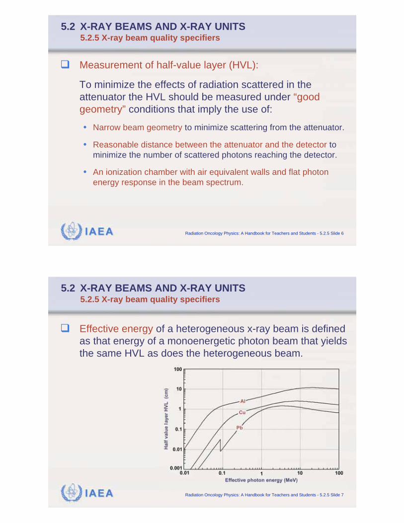
Effective energy of a heterogeneous x-ray beam is defined
as that energy of a monoenergetic photon beam that yields
the same HVL as does the heterogeneous beam.

IAEA Radiation Oncology Physics: A Handbook for Teachers and Students - 5.2.5 Slide 8
5.2 X-RAY BEAMS AND X-RAY UNITS5.2.5 X-ray beam quality specifiers
Nominal accelerating
potential (NAP)
• NAP was introduced in the
AAPM TG 21 dosimetry
protocol (1983) as a matter of
convenience and is related to
the energy of the electrons
striking the target.
• NAP is defined in terms of the
ionization ratio measured in
water on central beam axis at
a fixed SAD of 100 cm and a
field size of 10x10 cm2 for
depths z of 20 cm and 10 cm.
IAEA Radiation Oncology Physics: A Handbook for Teachers and Students - 5.2.5 Slide 9
5.2 X-RAY BEAMS AND X-RAY UNITS5.2.5 X-ray beam quality specifiers
Tissue-phantom ratio TPR20,10:
• TPR20,10 is defined as the ratio of doses on the beam central axis
at depths of z = 20 cm and z = 10 cm in water obtained at an SAD
of 100 cm and a field size of 10x10 cm2.
• TPR20,10 is independent of electron contamination of the incident
photon beam.
• TPR20,10 is used as megavoltage beam quality specifier in the
IAEA-TRS 398 dosimetry protocol.
• TPR20,10 is related to measured TPR20,10 as
. .20,10 20,10
TPR 1 2661 PDD 0 0595=

IAEA Radiation Oncology Physics: A Handbook for Teachers and Students - 5.2.5 Slide 10
5.2 X-RAY BEAMS AND X-RAY UNITS5.2.5 X-ray beam quality specifiers
Percentage depth dose PDD(10):
• PDD(10) is defined as the percentage depth dose measure in
water on the beam central axis for a 10x10 cm2 field and an SSD
of 100 cm.
• The problem of electron beam contamination of the megavoltage
photon beam is circumvented by placing a 1 mm thick lead foil
into the beam to remove the unknown electron contamination.
• The electron contamination contributed by the lead foil can be
assumed known and is determined with Monte Carlo calculations.
• PDD(10)x for the pure photon beam can be calculated from
PDD(10)Pb using a correction formula.
IAEA Radiation Oncology Physics: A Handbook for Teachers and Students - 5.2.6 Slide 1
5.2 X-RAY BEAMS AND X-RAY UNITS5.2.6 X-ray machines for radiotherapy
Superficial and orthovoltage
beams used in radiotherapy are
produced by x-ray machines.
The main components of a
radiotherapy x-ray machine are:
• X-ray tube
• Ceiling or floor mount for the x-ray
tube
• Target cooling system
• Control console
• X-ray power generator

IAEA Radiation Oncology Physics: A Handbook for Teachers and Students - 5.2.6 Slide 2
5.2 X-RAY BEAMS AND X-RAY UNITS5.2.6 X-ray machines for radiotherapy
The components of a
radiotherapy x-ray machine:
• X-ray tube
• Applicators
IAEA Radiation Oncology Physics: A Handbook for Teachers and Students - 5.2.6 Slide 3
5.2 X-RAY BEAMS AND X-RAY UNITS5.2.6 X-ray machines for radiotherapy
The main components of a typical therapy x-ray tube are:
• Water or oil cooled target (anode)
• Heated filament (cathode)
Based on Fig. 2.8,
Johns and Cunningham,
Physics of Radiology,
C.C. Thomas,
Springfield, Illinois, 1984
(reproduced with permission)
IAEA Radiation Oncology Physics: A Handbook for Teachers and Students - 5.2.6 Slide 4
5.2 X-RAY BEAMS AND X-RAY UNITS5.2.6 X-ray machines for radiotherapy
With x-ray tubes the patient dose is delivered using a
timer and the treatment time must incorporate a shutter
correction time.
In comparison with diagnostic radiology x-ray tubes, a
therapy x-ray tube operates:
• At about 10% of instantaneous current.
• At about 10 times average energy input.
• With significantly larger focal spot and a fixed rather than rotating
anode.
IAEA Radiation Oncology Physics: A Handbook for Teachers and Students - 5.3.1 Slide 1
5.3 GAMMA RAY BEAMS AND GAMMA RAY UNITS5.3.1 Basic properties of gamma rays
For use in external beam radiotherapy, gamma rays are
obtained from specially designed and built sources that
contain a suitable, artificially produced radionuclide.
The parent source material undergoes beta minus decay
resulting in excited daughter nuclei that attain ground
state through emission of gamma rays (gamma decay).

IAEA Radiation Oncology Physics: A Handbook for Teachers and Students - 5.3.1 Slide 2
5.3 GAMMA RAY BEAMS AND GAMMA RAY UNITS5.3.1 Basic properties of gamma rays
The important characteristics of radionuclides useful for
external beam radiotherapy are:
• High gamma ray energy (of the order of 1 MeV).
• High specific activity (of the order of 100 Ci/g).
• Relatively long half life (of the order of several years).
• Large specific air kerma rate constant.
Of over 3000 radionuclides known only 3 meet the
required characteristics and essentially only cobalt-60 is
currently used for external beam radiotherapy.
IAEA Radiation Oncology Physics: A Handbook for Teachers and Students - 5.3.1 Slide 3
5.3 GAMMA RAY BEAMS AND GAMMA RAY UNITS5.3.1 Basic properties of gamma rays
Specific activity a is defined as the activity A per mass
m of a radionuclide) is linearly proportional to the decay
constant and inversely proportional to the half-life t1/2
Specific activity
• Radium-226: a = 0.988 Ci/g (original definition: 1 Ci/g)
• Cobalt-60: a = 1130 Ci/g (carrier free); 300 Ci/g (in practice)
• Cesium-137: a = 80 Ci/g
A
1/2
ln2= = =
A NNa
m m t A

IAEA Radiation Oncology Physics: A Handbook for Teachers and Students - 5.3.1 Slide 4
5.3 GAMMA RAY BEAMS AND GAMMA RAY UNITS5.3.1 Basic properties of gamma rays
Air kerma rate in air is proportional to the specific
air kerma rate constant and inversely proportional to
d2, the distance between the source and the point of
interest
Specific air kerma rate constant in
• Cobalt-60:
• Cesium-137:
air air( )K
AKRair air 2
( ) =
AK
d
AKR
AKR [μGy m2 / (GBq h)]
2AKR 309 Gy m /(GBq h)μ=
2AKR 78 Gy m /(GBq h)μ=
IAEA Radiation Oncology Physics: A Handbook for Teachers and Students - 5.3.2 Slide 1
5.3 GAMMA RAY BEAMS AND GAMMA RAY UNITS5.3.2 Teletherapy machines
Treatment machines used for external beam radiotherapy
with gamma ray sources are called teletherapy machines.
They are most often mounted isocentrically with SAD of
80 cm or 100 cm.
The main components of a teletherapy machine are:
• Radioactive source
• Source housing, including beam collimator and source movement
mechanism.
• Gantry and stand.
• Patient support assembly.
• Machine control console.

IAEA Radiation Oncology Physics: A Handbook for Teachers and Students - 5.3.2 Slide 2
5.3 GAMMA RAY BEAMS AND GAMMA RAY UNITS5.3.2 Teletherapy machines
Cobalt-60 teletherapy machine, Theratron-780, AECL (now MDS Nordion), Ottawa, Canada
IAEA Radiation Oncology Physics: A Handbook for Teachers and Students - 5.3.2 Slide 3
5.3 GAMMA RAY BEAMS AND GAMMA RAY UNITS5.3.2 Teletherapy machines
Schematic diagram of a
cobalt-60 teletherapy
machine:
• Depicted on a postage
stamp issued by Canada
Post in 1988
• In honor of Harold E.
Johns, who invented the
cobalt-60 machine in the
1950s.
• Reprinted with permission
from Canada Post.

IAEA Radiation Oncology Physics: A Handbook for Teachers and Students - 5.3.3 Slide 1
5.3 GAMMA RAY BEAMS AND GAMMA RAY UNITS5.3.3 Teletherapy sources
To facilitate interchange of sources from one teletherapymachine to another and from one radionuclide productionfacility to another, standard source capsules have beendeveloped.
Teletherapy sources are cylinders with height of 2.5 cmand diameter of 1, 1.5, or 2 cm.
• The smaller is the source diameter, the smaller is the physicalbeam penumbra and the more expensive is the source.
• Often a diameter of 1.5 cm is chosen as a compromise betweenthe cost and penumbra.
IAEA Radiation Oncology Physics: A Handbook for Teachers and Students - 5.3.3 Slide 2
5.3 GAMMA RAY BEAMS AND GAMMA RAY UNITS5.3.3 Teletherapy sources
Typical source activity: of the order of 5 000 - 10 000 Ci
(185 - 370 TBq).
Typical dose rates at 80 cm from source: of the order of
100 - 200 cGy/min
Teletherapy source is usually replaced within one half-life
after it is installed. Financial considerations often result in
longer source usage.

IAEA Radiation Oncology Physics: A Handbook for Teachers and Students - 5.3.3 Slide 3
5.3 GAMMA RAY BEAMS AND GAMMA RAY UNITS5.3.3 Teletherapy sources
Teletherapy radionuclides: cobalt-60 and cesium-137
• Both decay through beta minus decay
• Half-life of cobalt-60 is 5.26 y; of cesium-137 is 30 y
• The beta particles (electrons) are absorbed in the source capsule.
IAEA Radiation Oncology Physics: A Handbook for Teachers and Students - 5.3.4 Slide 1
5.3 GAMMA RAY BEAMS AND GAMMA RAY UNITS5.3.4 Teletherapy source housing
The source head consists of:
• Steel shell with lead for shielding purposes
• Mechanism for bringing the source in front of the collimator
opening to produce the clinical gamma ray beam.
Currently, two methods are used for moving the tele-
therapy source from the BEAM-OFF into the BEAM-ON
position and back:
• Source on a sliding drawer
• Source on a rotating cylinder

IAEA Radiation Oncology Physics: A Handbook for Teachers and Students - 5.3.4 Slide 2
5.3 GAMMA RAY BEAMS AND GAMMA RAY UNITS5.3.4 Teletherapy source housing
Methods for moving the teletherapy source from the
BEAM-OFF into the BEAM-ON position and back:
Source on a sliding drawer Source on a rotating cylinder
IAEA Radiation Oncology Physics: A Handbook for Teachers and Students - 5.3.4 Slide 3
5.3 GAMMA RAY BEAMS AND GAMMA RAY UNITS5.3.4 Teletherapy source housing
Both methods (source-on-drawer and source-on-cylinder)
incorporate a safety feature in which the beam is terminated
automatically in the event of power failure or emergency.
When the source is in the BEAM-OFF position, a light
source appears in the BEAM-ON position above the
collimator opening, allowing an optical visualization of the
radiation field, as defined by the machine collimator.

IAEA Radiation Oncology Physics: A Handbook for Teachers and Students - 5.3.4 Slide 4
5.3 GAMMA RAY BEAMS AND GAMMA RAY UNITS5.3.4 Teletherapy source housing
Some radiation (leakage radiation) will escape from the
teletherapy machine even when the source is in the
BEAM-OFF position.
Head leakage typically amounts to less than 1 mR/h
(0.01 mSv/h) at 1 m from the source.
International regulations require that the average
leakage of a teletherapy machine head be less than 2
mR/h (0.02 mSv/h).
IAEA Radiation Oncology Physics: A Handbook for Teachers and Students - 5.3.5 Slide 1
5.3 GAMMA RAY BEAMS AND GAMMA RAY UNITS5.3.5 Dose delivery with teletherapy machines
The prescribed dose is delivered to the patient with the help
of two treatment timers: primary and secondary.
• The primary timer actually controls the treatment time and turns the
beam off upon reaching the prescribed beam-on time.
• The secondary timer serves as a backup timer in case of the primary
timer’s failure to turn the beam off.
The set treatment time should incorporate the shutter
correction time to account for the travel time of the source
from the BEAM-OFF to the BEAM-ON position at the start
of the irradiation and for the reverse travel at the end of
irradiation.

IAEA Radiation Oncology Physics: A Handbook for Teachers and Students - 5.3.6 Slide 1
5.3 GAMMA RAY BEAMS AND GAMMA RAY UNITS5.3.6 Collimator and penumbra
Collimators of teletherapy machines provide square and
rectangular radiation fields typically ranging from 5x5 to
35x35 cm2 at 80 cm from the source.
The geometric penumbra resulting from the finite source
diameter, may be minimized by using:
• Small source diameter
• Penumbra trimmers as close as
possible to the patient’s skin (z = 0)
P(z)
s=
(SSD + z SDD)
SDD
IAEA Radiation Oncology Physics: A Handbook for Teachers and Students - 5.4 Slide 1
5.4 PARTICLE ACCELERATORS
Many types of accelerator have been built for basic
research in nuclear physics and high energy physics.
Most of these accelerators have been modified for at
least some limited use in radiotherapy.
Irrespective of accelerator type, two basic conditions
must be met for particle acceleration:
• The particle to be accelerated must be charged
• Electric field must be provided in the direction of particle
acceleration

IAEA Radiation Oncology Physics: A Handbook for Teachers and Students - 5.4 Slide 2
5.4 PARTICLE ACCELERATORS
As far as the accelerating electric field is concerned there
are two main classes of accelerator: electrostatic and
cyclic.
• In electrostatic accelerators the particles are accelerated by
applying an electrostatic electric field through a voltage
difference, constant in time, whose value fixes the value of the
final kinetic energy of the particle.
• In cyclic accelerators the electric fields used for particle
acceleration are variable and associated with a variable
magnetic field. This results in some closed paths along which the
kinetic energy gained by the particle differs from zero.
IAEA Radiation Oncology Physics: A Handbook for Teachers and Students - 5.4 Slide 3
5.4 PARTICLE ACCELERATORS
Electrostatic accelerators used in medicine:
• Superficial and orthovoltage x-ray machines
• Neutron generators for cancer therapy
Cyclic accelerators used in medicine
• Linear accelerator (linac)
• Microtron
• Betatron
• Cyclotron
• Synchrotron

IAEA Radiation Oncology Physics: A Handbook for Teachers and Students - 5.4.1 Slide 1
5.4 PARTICLE ACCELERATORS5.4.1 Betatron
Betatron is a cyclic accelerator in which the electrons are
made to circulate in a toroidal vacuum chamber (doughnut)
that is placed into a gap between two magnet poles.
Conceptually, the betatron may be considered an analog of
a transformer:
• Primary current is the alternating current exciting the magnet.
• Secondary current is the electron current circulating in the doughnut.
IAEA Radiation Oncology Physics: A Handbook for Teachers and Students - 5.4.2 Slide 1
5.4 PARTICLE ACCELERATORS5.4.2 Cyclotron
In a cyclotron the particles are accelerated along a spiral
trajectory guided inside two evacuated half-cylindrical
electrodes (dees) by a uniform magnetic field produced
between the pole pieces of a large magnet (1 T).

IAEA Radiation Oncology Physics: A Handbook for Teachers and Students - 5.4.3 Slide 1
5.4 PARTICLE ACCELERATORS5.4.3 Microtron
Microtron is an electron accelerator that combines the
features of a linac and a cyclotron.
The electron gains energy from a resonant wave guide
cavity and describes circular orbits of increasing radius
in a uniform magnetic field.
After each passage through the
wave guide the electrons gain an
energy increment resulting in a
larger radius for the next pass
through the wave guide cavity.
IAEA Radiation Oncology Physics: A Handbook for Teachers and Students - 5.5 Slide 1
5.5 LINACS
Medical linacs are cyclic accelerators that accelerate
electrons to kinetic energies from 4 to 25 MeV using
microwave radiofrequency fields:
• 103 MHz : L band
• 2856 MHz: S band
• 104 MHz: X band
In a linac the electrons are accelerated following straight
trajectories in special evacuated structures called
accelerating waveguides.
IAEA Radiation Oncology Physics: A Handbook for Teachers and Students - 5.5.1 Slide 1
5.5 LINACS5.5.1 Linac generations
During the past 40 years medical linacs have gone
through five distinct generations, each one increasingly
more sophisticated:
(1) Low energy x rays (4-6 MV)
(2) Medium energy x rays (10-15 MV) and electrons
(3) High energy x rays (18-25 MV) and electrons
(4) Computer controlled dual energy linac with electrons
(5) Computer controlled dual energy linac with electrons
combined with intensity modulation
IAEA Radiation Oncology Physics: A Handbook for Teachers and Students - 5.5.2 Slide 1
5.5 LINACS5.5.2 Safety of linac installations
Safety of operation for the patient, operator, and the
general public is of great concern because of the
complexity of modern linacs.
Three areas of safety are of interest
• Mechanical
• Electrical
• Radiation
Many national and international bodies are involved
with issues related to linac safety.

IAEA Radiation Oncology Physics: A Handbook for Teachers and Students - 5.5.3 Slide 1
5.5 LINACS5.5.3 Components of modern linacs
Linacs are usually mounted isocentrically and the
operational systems are distributed over five major and
distinct sections of the machine:
• Gantry
• Gantry stand and support
• Modulator cabinet
• Patient support assembly
• Control console
IAEA Radiation Oncology Physics: A Handbook for Teachers and Students - 5.5.3 Slide 2
5.5 LINACS5.5.3 Components of modern linacs
The main beam forming components of a modern medical
linac are usually grouped into six classes:
(1) Injection system
(2) Radiofrequency power generation system
(3) Accelerating waveguide
(4) Auxiliary system
(5) Beam transport system
(6) Beam collimation and monitoring system

IAEA Radiation Oncology Physics: A Handbook for Teachers and Students - 5.5.3 Slide 3
5.5 LINACS5.5.3 Components of modern linacs
Schematic diagram of a modern fifth generation linac
IAEA Radiation Oncology Physics: A Handbook for Teachers and Students - 5.5.4 Slide 1
5.5 LINACS5.5.4 Configuration of modern linacs
In the simplest and most practical configuration:
• Electron source and the x-ray target form part of the
accelerating waveguide and are aligned directly with the linac
isocentre obviating the need for a beam transport system.
• Since the target is embedded into the waveguide, this linac type
cannot produce electron beams.

IAEA Radiation Oncology Physics: A Handbook for Teachers and Students - 5.5.4 Slide 2
5.5 LINACS5.5.4 Configuration of modern linacs
Accelerating waveguides for intermediate (8-15 MV)
and high (15-30 MV) energy linacs are located:
• Either in the gantry parallel to the gantry axis of rotation
• Or in the gantry stand.
• In both cases, a beam transport system is used to transport the
electron beam from the accelerating waveguide to the x-ray
target.
• The radiofrequency power source in both configurations is
mounted in the gantry stand
IAEA Radiation Oncology Physics: A Handbook for Teachers and Students - 5.5.4 Slide 3
5.5 LINACS5.5.4 Linac generations
Configurations for intermediate and high energy linacs
Waveguide in the gantry
RF power source in gantry stand
Waveguide in the gantry stand
RF power source in gantry stand

IAEA Radiation Oncology Physics: A Handbook for Teachers and Students - 5.5.4 Slide 4
5.5 LINACS5.5.4 Linac generations
Typical
modern dual
energy
linac,incorporating
imaging
system and
electronic
portal imaging
device (EPID),
Elekta,
Stockholm
IAEA Radiation Oncology Physics: A Handbook for Teachers and Students - 5.5.4 Slide 5
5.5 LINACS5.5.4 Linac generations
Typical modern dual
energy linac, with on board
imaging system and an
electronic portal imaging
device (EPID),
Varian, Palo Alto, CA

IAEA Radiation Oncology Physics: A Handbook for Teachers and Students - 5.5.5 Slide 1
5.5 LINACS5.5.5 Injection system
The linac injection system is the source of electrons, a
simple electrostatic accelerator referred to as the
electron gun.
Two types of electron gun are in use in medical linacs:
• Diode type
• Triode type
Both electron gun types contain:
• Heated filament cathode
• Perforated grounded anode
• Triode gun also incorporates a grid
IAEA Radiation Oncology Physics: A Handbook for Teachers and Students - 5.5.5 Slide 2
5.5 LINACS5.5.5 Injection system
Two types of electron gun producing electrons in linac:

IAEA Radiation Oncology Physics: A Handbook for Teachers and Students - 5.5.6 Slide 1
5.5 LINACS5.5.6 Radiofrequency power generation system
The radiofrequency power
generation system produces
the microwave radiation used
in the accelerating
waveguide to accelerate
electrons to the desired
kinetic energy and consists of
two major components:
• RF power source
(magnetron or klystron)
• Pulsed modulator
IAEA Radiation Oncology Physics: A Handbook for Teachers and Students - 5.5.6 Slide 2
5.5 LINACS5.5.6 Radiofrequency power generation system
Pulsed modulator produces the high voltage ( 100 kV),
high current ( 100 A), short duration ( 1 s) pulses
required by the RF power source and the injection
system.
μ

IAEA Radiation Oncology Physics: A Handbook for Teachers and Students - 5.5.7 Slide 1
5.5 LINACS5.5.7 Accelerating waveguide
Waveguides are evacuated or gas filled metallic
structures of rectangular or circular cross-section used in
transmission of microwaves.
Two types of waveguide are used in linacs:
• Radiofrequency power transmission waveguides (gas filled) for
transmission of the RF power from the power source to the
accelerating waveguide.
• Accelerating waveguides (evacuated to about 10-6 tor) for
acceleration of electrons.
IAEA Radiation Oncology Physics: A Handbook for Teachers and Students - 5.5.7 Slide 2
5.5 LINACS5.5.7 Accelerating waveguide
Accelerating waveguide is obtained from a cylindrical
uniform waveguide by adding a series of disks (irises) with
circular holes at the centre, placed at equal distances
along the tube to form a series of cavities.
The accelerating waveguide is evacuated to allow free
propagation of electrons.
The cavities serve two purposes:
• To couple and distribute microwave
power between cavities.
• To provide a suitable electric field
pattern for electron acceleration.

IAEA Radiation Oncology Physics: A Handbook for Teachers and Students - 5.5.7 Slide 3
5.5 LINACS5.5.7 Accelerating waveguide
The role of the disks (irises) is to slow the phase velocity of
the RF wave to a velocity below the speed of light in
vacuum to allow acceleration of electrons.
The accelerating waveguide is evacuated (10-6 tor) to allow
free propagation of electrons.
The cavities serve two purposes:
• To couple and distribute microwave power between adjacent
cavities.
• To provide a suitable electric field pattern for electron acceleration.
IAEA Radiation Oncology Physics: A Handbook for Teachers and Students - 5.5.7 Slide 4
5.5 LINACS5.5.7 Accelerating waveguide
Two types of accelerating waveguide are in use:
• Traveling wave structure
• Standing wave structure

IAEA Radiation Oncology Physics: A Handbook for Teachers and Students - 5.5.7 Slide 5
5.5 LINACS5.5.7 Accelerating waveguide
In the travelling wave accelerating structure the
microwaves enter on the gun side and propagate toward
the high energy end of the waveguide.
Only one in four cavities is at any given moment suitable
for acceleration.
IAEA Radiation Oncology Physics: A Handbook for Teachers and Students - 5.5.7 Slide 6
5.5 LINACS5.5.7 Accelerating waveguide
In the standing wave accelerating structure each end of
the accelerating waveguide is terminated with a
conducting disk to reflect the microwave power producing
a standing wave in the waveguide.
Every second cavity carries
no electric field and thus
produces no energy gain
for the electron
(coupling cavities).

IAEA Radiation Oncology Physics: A Handbook for Teachers and Students - 5.5.8 Slide 1
5.5 LINACS5.5.8 Microwave power transmission
The microwave power produced by the RF generator is
carried to the accelerating waveguide through rectangular
uniform waveguides usually pressurized with a dielectric
gas (freon or sulphur hexafluoride SF6).
Between the RF generator and the accelerating waveguide
is a circulator (isolator) which transmits the RF power from
the RF generator to the accelerating waveguide but does
not transmit microwaves in the opposite direction.
IAEA Radiation Oncology Physics: A Handbook for Teachers and Students - 5.5.9 Slide 1
5.5 LINACS5.5.9 Auxiliary system
Auxiliary service consists of four systems that are not
directly involved with electron acceleration:
• Vacuum pumping system producing high vacuum in the accelerating
waveguide.
• Water cooling system for cooling the accelerating waveguide, target,
circulator and RF generator.
• Air pressure system for pneumatic movement of the target and other
beam shaping components.
• Shielding against leakage radiation produced by target, beam
transport system and RF generator.

IAEA Radiation Oncology Physics: A Handbook for Teachers and Students - 5.5.10 Slide 1
5.5 LINACS5.5.10 Electron beam transport
In medium-energy and high-energy linacs an electron
beam transport system is used to transport electrons
from the accelerating waveguide to:
• X-ray target in x-ray beam therapy
• Beam exit window in electron beam therapy
Beam transport system consists of:
• Drift tubes
• Bending magnets
• Steering coild
• Focusing coils
• Energy slits
IAEA Radiation Oncology Physics: A Handbook for Teachers and Students - 5.5.10 Slide 2
5.5 LINACS5.5.10 Electron beam transport
Three systems for electron
beam bending have been
developed:
• 90o bending
• 270o bending
• 112.5o (slalom) bending

IAEA Radiation Oncology Physics: A Handbook for Teachers and Students - 5.5.11 Slide 1
5.5 LINACS5.5.11 Linac treatment head
Electrons forming the electron pencil beam:
• Originate in the electron gun.
• Are accelerated in the accelerating waveguide to the desired
kinetic energy.
• Are brought through the beam transport system into the linac
treatment head.
The clinical x-ray beams or clinical electron beams are
produced in the linac treatment head.
IAEA Radiation Oncology Physics: A Handbook for Teachers and Students - 5.5.11 Slide 2
5.5 LINACS5.5.11 Linac treatment head
Components of a modern linac treatment head:
• Several retractable x-ray targets (one for each x-ray beam energy).
• Flattening filters (one for each x-ray beam energy).
• Scattering foils for production of clinical electron beams.
• Primary collimator.
• Adjustable secondary collimator with independent jaw motion.
• Dual transmission ionization chamber.
• Field defining light and range finder.
• Retractable wedges.
• Multileaf collimator (MLC).

IAEA Radiation Oncology Physics: A Handbook for Teachers and Students - 5.5.11 Slide 3
5.5 LINACS5.5.11 Linac treatment head
Clinical x-ray beams are produced with:
• Appropriate x-ray target.
• Appropriate flattening filter.
Clinical electron beams are produced by:
• Either scattering the pencil electron beam with an appropriate
scattering foil.
• Or deflecting and scanning the pencil beam magnetically to
cover the field size required for electron treatment.
The flattening filters and scattering foils are mounted on
a rotating carousel or sliding drawer.
IAEA Radiation Oncology Physics: A Handbook for Teachers and Students - 5.5.11 Slide 4
5.5 LINACS5.5.11 Linac treatment head
Electrons:
• Originate in the electron gun.
• Are accelerated in the accelerating waveguide to the desired
kinetic energy.
• Are brought through the beam transport system into the linac
treatment head.
The clinical x-ray beams and clinical electron beams are
produced in the linac treatment head.

IAEA Radiation Oncology Physics: A Handbook for Teachers and Students - 5.5.12 Slide 1
5.5 LINACS5.5.12 Production of clinical x-ray beams
Megavoltage clinical x-ray beams:
• Are produced in a linac x-ray target
• Are flattened with a flattening filter.
IAEA Radiation Oncology Physics: A Handbook for Teachers and Students - 5.5.12 Slide 2
5.5 LINACS5.5.12 Production of clinical x-ray beams
Typical electron pulses arriving on the x-ray target of a
linac.
The target is insulated from ground, acts as a Faraday
cup, and allows measurement of the electron charge
striking the target.
Typical values:Pulse height: 50 mA
Pulse duration: 2 μs
Repetition rate: 100 pps
Period: 104 μs

IAEA Radiation Oncology Physics: A Handbook for Teachers and Students - 5.5.13 Slide 1
5.5 LINACS5.5.13 Beam collimation
In modern linacs the x-ray beam collimation is achieved with
three collimation devices:
• Primary collimator.
• Secondary adjustable beam defining collimator (independent jaws).
• Multileaf collimator (MLC).
The electron beam collimation is achieved with:
• Primary collimator.
• Secondary collimator.
• Electron applicator (cone).
• Multileaf collimator (under development).
IAEA Radiation Oncology Physics: A Handbook for Teachers and Students - 5.5.14 Slide 1
5.5 LINACS5.5.14 Production of clinical electron beam
To activate the electron mode
the x-ray target and flattening
filter are removed from the
electron pencil beam.
Two techniques for producing
clinical electron beams from the
pencil electron beam:
• Pencil beam scattering with a
scattering foil (thin foil of lead).
• Pencil beam scanning with two
computer controlled magnets.

IAEA Radiation Oncology Physics: A Handbook for Teachers and Students - 5.5.15 Slide 1
5.5 LINACS5.5.15 Dose monitoring system
To protect the patient, the standards for dose monitoring
systems in clinical linacs are very stringent.
The standards are defined for:
• Type of radiation detector.
• Display of monitor units.
• Methods for beam termination.
• Monitoring the dose rate.
• Monitoring the beam flatness.
• Monitoring beam energy.
• Redundancy systems.
IAEA Radiation Oncology Physics: A Handbook for Teachers and Students - 5.5.15 Slide 2
5.5 LINACS5.5.15 Dose monitoring system
Transmission ionization chambers, permanently
embedded in the linac clinical x-ray and electron beams,
are the most common dose monitors in linacs.
Transmission ionization chambers consist of two
separately sealed ionization chambers with completely
independent biasing power supplies and readout
electrometers for increased patient safety.

IAEA Radiation Oncology Physics: A Handbook for Teachers and Students - 5.5.15 Slide 3
5.5 LINACS5.5.15 Dose monitoring system
Most linac transmission ionization chambers are
permanently sealed, so that their response is not affected
by ambient air temperature and pressure.
The customary position for the transmission ionization
chamber is between the flattening filter (for x-ray beams) or
scattering foil (for electron beams) and the secondary
collimator.
IAEA Radiation Oncology Physics: A Handbook for Teachers and Students - 5.5.15 Slide 4
5.5 LINACS5.5.15 Dose monitoring system
The primary transmission ionization chamber measures
the monitor units (MUs).
Typically, the sensitivity of the primary chamber
electrometer is adjusted in such a way that:
• 1 MU corresponds to a dose of 1 cGy
• delivered in a water phantom at the depth of dose maximum
• on the central beam axis when
• for a 10x10 cm2 field
• at a source-surface distance (SSD) of 100 cm.

IAEA Radiation Oncology Physics: A Handbook for Teachers and Students - 5.5.15 Slide 5
5.5 LINACS5.5.15 Dose monitoring system
Once the operator preset number of MUs has been
reached, the primary ionization chamber circuitry:
• Shuts the linac down.
• Terminates the dose delivery to the patient.
Before a new irradiation can be initiated:
• MU display must be reset to zero.
• Irradiation is not possible until a new selection of MUs and
beam mode has been made.
IAEA Radiation Oncology Physics: A Handbook for Teachers and Students - 5.6 Slide 1
5.6 RADIOTHERAPY WITH PROTONS, NEUTRONS
External beam radiotherapy is carried out mainly with
machines that produce either x-rays or electrons.
In a few specialized centres around the world, external
beam radiotherapy is also carried out with heavier
particles, such as:
• Neutrons produced by cyclotrons or neutron generators
• Protons produced by cyclotrons or synchrotrons
• Heavy ions (helium, carbon, nitrogen, argon, neon) produced by
synchrocyclotrons or synchrotrons.

IAEA Radiation Oncology Physics: A Handbook for Teachers and Students - 5.6 Slide 2
5.6 RADIOTHERAPY WITH PROTONS AND NEUTRONS
Percentage depth dose against depth in water for radiation
beams of various types and energies:
(a) Photons
(b) Neutrons
(c) Electrons
(d) Heavy
charged
particles
IAEA Radiation Oncology Physics: A Handbook for Teachers and Students - 5.6 Slide 3
5.6 RADIOTHERAPY WITH PROTONS, NEUTRONS
Advantages of neutron, proton and heavy charged particle
beams over the standard x ray and electron modalities:
• Lower oxygen enhancement ratio (OER) for neutrons
• Improved dose-volume histograms (DVHs) for protons and heavy
charged particles.
Disadvantage of neutron, proton and heavy charge particle
beams in comparison with standard x ray and electron
modalities: considerably higher capital, maintenance and
servicing cost.

IAEA Radiation Oncology Physics: A Handbook for Teachers and Students - 5.7 Slide 1
5.7 SHIELDING CONSIDERATIONS
External beam radiotherapy is carried out mainly with three
types of equipment that produces either x rays or electrons
for clinical use:
• X-ray machines (superficial or orthovoltage).
• Cobalt-60 teletherapy machines.
• Linacs.
All radiotherapy equipment must be housed in specially
shielded treatment rooms in order to protect personnel and
general public in areas adjacent to the treatment rooms.
IAEA Radiation Oncology Physics: A Handbook for Teachers and Students - 5.7 Slide 2
5.7 SHIELDING CONSIDERATIONS
Treatment rooms must comply:
• Not only with structural building codes
• But also with national and international regulations that deal with
shielding requirements to render an installation safe from the
radiation protection point of view.
During the planning stage for a radiotherapy machine
installation, a qualified medical physicist:
• Determines the required thickness of primary and secondary
barriers
• Provides the information to the architect and structural engineer for
incorporation into the architectural drawing for the treatment room.

IAEA Radiation Oncology Physics: A Handbook for Teachers and Students - 5.7 Slide 3
5.7 SHIELDING CONSIDERATIONS
Superficial and orthovoltage x-ray therapy rooms are
shielded:
• Either with ordinary concrete (density: 2.35 g/cm3)
• Or lead (density: 11.36 g/cm3, atomic number: 82)
In this energy range the photoelectric effect is the
predominant mode of photon interaction with matter,
making the use of lead very efficient for shielding
purposes.
IAEA Radiation Oncology Physics: A Handbook for Teachers and Students - 5.7 Slide 4
5.7 SHIELDING CONSIDERATIONS
Megavoltage treatment rooms are often referred to as
bunkers or vaults because of the large primary and
secondary barrier thicknesses required for shielding.
Megavoltage bunkers are most commonly shielded with
ordinary concrete so as to minimize construction cost.
The Compton effect is the predominant mode of photon
interaction with shielding material in the megavoltage
energy region. The barrier thickness is thus scaled inversely
with density of the shielding material.

IAEA Radiation Oncology Physics: A Handbook for Teachers and Students - 5.8 Slide 1
5.8 COBALT-60 TELETHERAPY UNITS VERSUS LINACS
Cobalt-60 teletherapy unit, developed in Canada in 1950s,
was the first truly practical megavoltage therapy machine.
The important features of a teletherapy source are:
• Relatively high energy gamma ray emission
• Relatively long half-life
• Relatively high specific activity
• Relatively high specific air kerma rate constant
• Relatively simple means of production
IAEA Radiation Oncology Physics: A Handbook for Teachers and Students - 5.8 Slide 2
5.8 COBALT-60 TELETHERAPY UNITS VERSUS LINACS
Typical cobalt-60
teletherapy installation:
isocentric machine
• Primary barriers shield
against the primary
cobalt-60 beam.
• Secondary barriers shield
against leakage radiation
and radiation scattered
from the patient.

IAEA Radiation Oncology Physics: A Handbook for Teachers and Students - 5.8 Slide 3
5.8 COBALT-60 TELETHERAPY UNITS VERSUS LINACS
Of the close to 300 natural nuclides and over 3000
artificially produced radionuclides:
• four meet the teletherapy source requirements (Co-60, Cs-137, Eu-
152, and Ra-226) and only cobalt-60 is actually used in practice.
Radionuclide Co-60 Cs-137 Eu-152 Ra-226
Half-life (y) 5.26 30 13.4 1600
Energy (MeV) 1.25, 1.33 0.660 0.6-1.4 0.18-2.2
Specific activity (Ci/g) 1130( 300) 80 180( 150) 0.988
309 78 250 194
Means of production 59Co+n Fission 151Eu+n Natural
in reactor by-product in reactor 238U series
μ 2AKR [ Gy m /(GBq h)]
IAEA Radiation Oncology Physics: A Handbook for Teachers and Students - 5.8 Slide 4
5.8 COBALT-60 TELETHERAPY UNITS VERSUS LINACS

IAEA Radiation Oncology Physics: A Handbook for Teachers and Students - 5.8 Slide 5
5.8 COBALT-60 TELETHERAPY UNITS VERSUS LINACS
Both the cobalt-60 teletherapy machine and clinical linac
were introduced in 1950s and used for megavoltage
radiotherapy since then.
During the past 50 years:
• The basic design of the cobalt machine remained essentially the
same.
• Linac progressed to the current design through five generations,
eclipsed the cobalt machine, and became the most widely used
radiation source in modern radiotherapy, with several 1000 units in
clinical practice around the world today.
IAEA Radiation Oncology Physics: A Handbook for Teachers and Students - 5.8 Slide 6
5.8 COBALT-60 TELETHERAPY UNITS VERSUS LINACS
In comparison with cobalt-60 teletherapy machines
linacs have become very complex in design:
• Because of the multimodality capabilities that have evolved
and are available on most modern linacs (several x-ray
energies and several electron energies).
• Because of an increased use of computer logic and
microprocessors in the control systems of linacs.
• Because of added features, such as high dose rate modes,
multileaf collimation, electron arc therapy, and the dynamic
treatment option on the collimators (dynamic wedge), MLC
leaves (IMRT), gantry or table while the beam is turned on.

IAEA Radiation Oncology Physics: A Handbook for Teachers and Students - 5.8 Slide 7
5.8 COBALT-60 TELETHERAPY UNITS VERSUS LINACS
Despite clear technological and practical advantages of
linacs over cobalt-60 machines, the latter still occupy an
important place in radiotherapy armamentarium,
especially in developing countries, because of:
• Their considerably lower capital and installation cost.
• Lower servicing and maintenance cost.
• Lesser dependence on reliable electrical power.
• Simplicity of design.
• Ease of operation.
IAEA Radiation Oncology Physics: A Handbook for Teachers and Students - 5.9 Slide 1
5.9 SIMULATORS AND CT SIMULATORS
Simulators and CT simulators cover several important
steps in the radiotherapeutic process related to:
• Determination of target location within the patient.
• Determination of the target shape and volume.
• Determination of the location of critical structures adjacent to
treatment volume.
• Planning of dose delivery procedure (treatment planning).
• Accuracy of dose delivery to the target.

IAEA Radiation Oncology Physics: A Handbook for Teachers and Students - 5.9.1 Slide 1
5.9 SIMULATORS AND CT SIMULATORS5.9.1 Radiotherapy simulator
Radiotherapy simulator
consists of a diagnostic
x-ray tube
mounted on a rotating
gantry
to simulate geometries of
isocentric teletherapy
machines and isocentric
linacs.
IAEA Radiation Oncology Physics: A Handbook for Teachers and Students - 5.9.1 Slide 2
5.9 SIMULATORS AND CT SIMULATORS5.9.1 Radiotherapy simulator
The simulator enjoys the same degrees of freedom as a
megavoltage therapy machine, however:
Rather than providing a megavoltage beam for dose
delivery
It provides a diagnostic quality x-ray beam suitable for
planar imaging (fluoroscopy and radiography) and cone
beam CT.

IAEA Radiation Oncology Physics: A Handbook for Teachers and Students - 5.9.1 Slide 3
5.9 SIMULATORS AND CT SIMULATORS5.9.1 Radiotherapy simulator
In megavoltage machines, radiation fields are defined with
collimators (upper and lower jaws).
In simulators radiation fields (square and rectangular) are
indicated with delineator wires while the radiation field,
defined with a collimator, provides a field that exceeds in
size the delineated field to enable visualization of the
target as well as healthy tissues adjacent to the target.
IAEA Radiation Oncology Physics: A Handbook for Teachers and Students - 5.9.1 Slide 4
5.9 SIMULATORS AND CT SIMULATORS5.9.1 Radiotherapy simulator
Modern simulator covers the following processes:
• Tumour and adjacent normal tissue localization.
• Treatment simulation.
• Treatment plan verification.
• Monitoring of treatment.
The design specifications and quality assurance processes
for a simulator cover four distinct components:
• Mechanical motions.
• Electrical.
• X-ray tube and generator.
• Image detection.

IAEA Radiation Oncology Physics: A Handbook for Teachers and Students - 5.9.2 Slide 1
5.9 SIMULATORS AND CT SIMULATORS5.9.2 CT simulator
CT simulators are CT scanners equipped with special
features dedicated to the radiotherapy process, such as:
• Flat table top surface to provide a patient position during
simulation that will be identical to the position during treatment on
a megavoltage machine.
• Laser marking system to transfer the coordinates of the tumour
isocentre to the surface of the patient.
• Virtual simulator consisting of software packages to allow the user
to define and calculate a treatment isocentre and then simulate a
treatment using digitally reconstructed radiographs (DRRs).
IAEA Radiation Oncology Physics: A Handbook for Teachers and Students - 5.9.2 Slide 2
5.9 SIMULATORS AND CT SIMULATORS5.9.2 CT simulator
Oncology CT
simulator (Philips)
Bore opening: 85 cm
Flat table top

IAEA Radiation Oncology Physics: A Handbook for Teachers and Students - 5.9.2 Slide 3
5.9 SIMULATORS AND CT SIMULATORS
5.9.2 CT simulator
The major steps in the target localization and field design are:
Physical simulation
(1) Acquisition of the patient data set.
(2) Localization of target and adjacent structures.
(3) Definition and marking of the patient coordinate system.
Virtual simulation
(1) Design of treatment fields.
(2) Transfer of data to the treatment planning system (TPS).
(3) Production of images used for treatment verification.
IAEA Radiation Oncology Physics: A Handbook for Teachers and Students - 5.9.2 Slide 4
5.9 SIMULATORS AND CT SIMULATORS5.9.2 CT simulator
CT simulation process:
The patient data set is collected and target localization is
carried out using CT axial images.
Laser alignment system is used for marking.
Virtual simulator software package is used for field design
and production of verification images (DRRs).
Transfer of patient data to the TPS is achieved
electronically.

IAEA Radiation Oncology Physics: A Handbook for Teachers and Students - 5.9.2 Slide 5
5.9 SIMULATORS AND CT SIMULATORS5.9.2 CT simulator
Digitally reconstructed radiograph (DRR) is the digital
equivalent of a planar simulation x-ray film.
DRR is reconstructed from a CT data set using virtual
simulation software available on CT simulator or on TPS
DRR represents a computed radiograph of a virtual patient
generated from a CT data set representing the actual
patient.
Like a conventional radiograph, the DRR accounts for
beam divergence.
IAEA Radiation Oncology Physics: A Handbook for Teachers and Students - 5.9.2 Slide 6
5.9 SIMULATORS AND CT SIMULATORS5.9.2 CT simulator
Steps involved in producing a DRR:
• Choice of virtual source position.
• Definition of image plane.
• Ray tracing from virtual source to image plane.
• Determination of the CT value for each volume element traversed
by the ray line to generate an effective transmission value at each
pixel of the image plane.
• Summation of CT values along the ray line (line integration).
• Grey scale mapping.
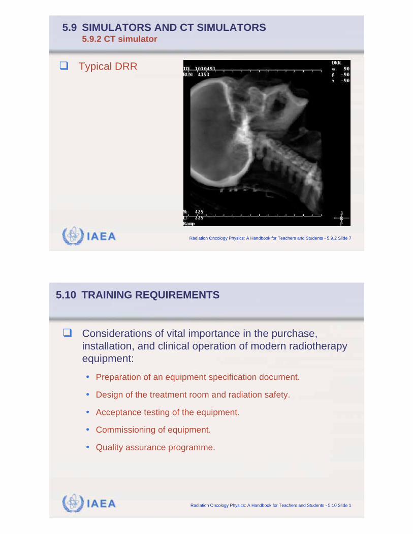
IAEA Radiation Oncology Physics: A Handbook for Teachers and Students - 5.9.2 Slide 7
5.9 SIMULATORS AND CT SIMULATORS5.9.2 CT simulator
Typical DRR
IAEA Radiation Oncology Physics: A Handbook for Teachers and Students - 5.10 Slide 1
5.10 TRAINING REQUIREMENTS
Considerations of vital importance in the purchase,
installation, and clinical operation of modern radiotherapy
equipment:
• Preparation of an equipment specification document.
• Design of the treatment room and radiation safety.
• Acceptance testing of the equipment.
• Commissioning of equipment.
• Quality assurance programme.