chapter 5 - pond design chapter - auckland council · auckland regional council technical...
TRANSCRIPT
5-1Auckland Regional Council Technical Publication # 10
Chapter 5Pond design,construction, and maintenance
5.1 Introduction
Stormwater management ponds have been used in the Auckland Region for years, initially for water quantitycontrol, but more recently also for water quality control. They have been, and are expected to remain,important components in the ARC stormwater effort to minimise adverse impacts associated with urban landuse. This Chapter reviews ponds that are either normally dry or normally wet. Both forms of pond can andmay possibly have an extended detention component to them. This Chapter does not include discussion ofwetland ponds. Wetland ponds, while having much in common with deeper ponds are being consideredseparately within Chapter 6, a more detailed discussion of the additional functions that they provide.
Ponds are defined as:
Dry pond - A permanent pond that temporarily stores stormwater runoff to control the peak rate of dis-charges and provide water quality treatment, primarily through the incorporation of extendeddetention. These ponds are normally dry between storm events.
Wet pond - A permanent pond that has a standing pool of water. These ponds can, through their normalstorage of water, or or in conjunction with extended detention, provide water quality treatment.They can, also in conjunction with extended detention, provide protection of downstream chan-nels from frequent storms.
Stormwater ponds are used for three primary purposes:> Reducing downstream flood potential,> Providing water quality treatment, and> Minimising, to the extent possible, downstream channel erosion.
It may not be necessary in every situation to address all three purposes, but there will be sites, as discussedlater in the Chapter, where all three functions will be included in the design.
5.2 Water quantity/quality performance
Ponds detain runoff, typically from a design storm, and then discharge it, usually at the pre-development peakdischarge rate.
Traditionally ponds, especially dry ones, have been used primarily for flood protection. They normally detainrunoff and then discharge it at a specified rate, reducing the potential for downstream flooding by delayingthe arrival of runoff from upper parts of a catchment. More recently, wet and dry pond designs have beenmodified to extend the detention time of runoff thereby increasing particulate contaminant settling and minimisingdownstream channel erosion. Wet ponds are normally designed to have a permanent pool for storage of aspecified water quality volume, in the Auckland Region, this is 1/3 of the 2 year frequency storm. Wet pondsalso have an outlet design that increases residence time and flow path.
5.2.1 Contaminant removal mechanism
The primary contaminant removal mechanism of all pond systems is settling or sedimentation. However, the

5-2Auckland Regional Council Technical Publication # 10
effectiveness may vary to some degree depending on the type of detention system (dry or wet).
Flood detention ponds have limited effectiveness at providing sedimentation as detention times may be severalhours only, so only the coarser particles can be removed from the water column.
Extended detention ponds that are normally dry also rely on sedimentation during shore periods of live storageonly although they typically hold flows for longer than flood detention ponds.
The best approach for particulate removal is the combination of extended detention in conjunction with anormal wet pool. The pool allows for displacement of water previously stored and the extended detentionallows for better sedimentation of excess storm flows.
5.2.2 Expected performance
Ponds can be effective at reducing peak discharge rates. Depending on their design and their location withina catchment, they may also be effective in reducing downstream channel erosion, downstream flood levelsand flooding.
Effectiveness at contaminant removal depends on the type of pond system. In general, they can be ranked,from least to most effective, in their ability to remove stormwater contaminants: dry detention, extended drydetention, and then wet detention.
Unlike dry detention ponds, wet ponds provide mechanisms that promote the removal of dissolved stormwatercontaminants, and not just particulates. Table 5-1 illustrates expected contaminant reduction.
Table 5-1Expected contaminant reduction range of ponds (in %)(WMI, 1997)
Contaminant Dry (flood) Dry (ext. det.) WetTotal suspended solids 20-60 30-80 50-90Total phosphorus 10-30 15-40 30-80Total Nitrogen 10-20 10-40 30-60COD 20-40 20-50 30-70Total Lead 20-60 20-70 30-90Total Zinc 10-50 10-60 30-90Total Copper 10-40 10-50 20-80Bacteria 20-40 20-60 20-80
Data from the Auckland Region for TSS removal efficiencies from three wet stormwater managementponds (Pacific Steel, Hayman Park and Unitech) is in Table 5-2:
Table 5-2Stormwater treatment pond monitoring in Auckland
Pond Reference Monitoring period Number of events monitored
Pacific Steel, Otahuhu Leersnyder (1993) 3-1/2 months 6 Hayman Park, Manukau Leersnyder (1993) 1-1/2 months 4 Unitech, Mount Albert McKergow (1994) 1 month 6
The water quality volume and expected sediment reduction for each pond were determined in accordancewith the design procedures from the previous version of TP 10. The relevant design parameters, expectedTSS removal efficiencies, and the monitored sediment inflow and outflow average event mean concentrations(EMC) of TSS removal are summarised in Table 5-3.
5-3Auckland Regional Council Technical Publication # 10
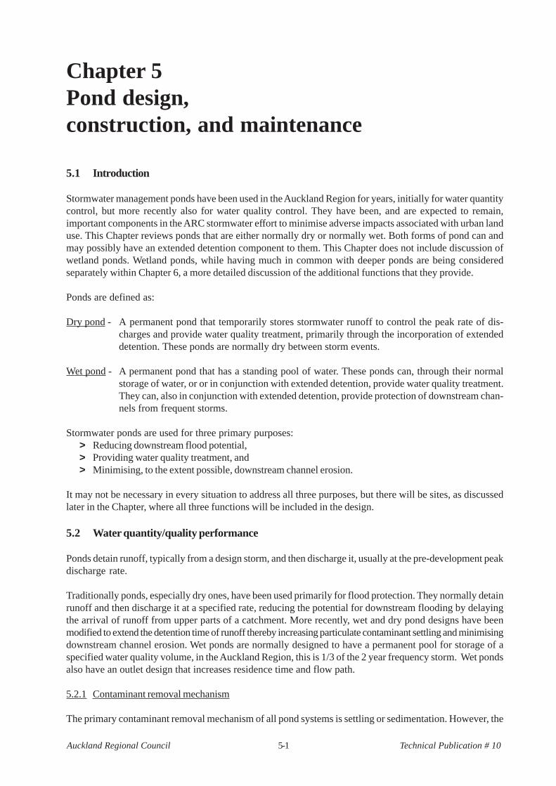
Table 5-3TSS removal efficiencies for Auckland pond studies
Pond Catchment Imperviousness Average TP 10 Actual TSS removal area (ha) (%) pond design pond efficiency
depth (m) volume (m3) volume (m3) Pacific Steel 9.7 approx. 100 0.71 1455 4750 78 Hayman Park 6.3 61 0.57 550 1757 71 Unitech 41.5 60 1.00 5380 5000 83
As can be seen from the local data, only a small number of events were monitored so they do not necessarilyindicate long term removal efficiency. This would require a long term monitoring programme to achieve areasonable degree of confidence. The results are only indicative of the pond’s TSS removal capability.
5.2.3 Constraints on the use of ponds
Dry ponds> Need fairly porous soils or subsurface drainage to assure that the bottom stays dry between storms> Not suitable in areas with high water tables or shallow depth to bedrock> Not suitable on fill sites or steep slopes unless geotechnically checked> May not be suitable if receiving water is temperature sensitive as detention ponds do not detain water
long enough to reduce temperatures from impervious surfaces.
Wet ponds> Not suitable on fill sites or near steep slopes unless geotechnically checked> May need supplemental water supply or liner system to maintain permanent pool if not dug into the
groundwater> Minimum contributing drainage area of 2 - 3 hectares is needed to maintain the permanent pool> Not feasible in very dense urban areas or areas with high land costs due to large surface area needs> May not be suitable if receiving water is temperature sensitive due to warming of pond surface area.> Safety issues need to be addressed, depending on normal pool depth
Dry flood detention ponds are not normally recommended for stormwater management systems. They haveongoing maintenance needs because standing water in areas where positive drainage is impeded may causemosquito problems, and their overall performance for water quality treatment is less than than provided bywet ponds. A study in the U.S. (DNR. 1986) indicated that over 70% of the dry ponds in a given jurisdictionwere not functioning as designed. In addition, dry ponds tend to have less aesthetic appeal than wet ponds.
5.3 Pond component disclaimer
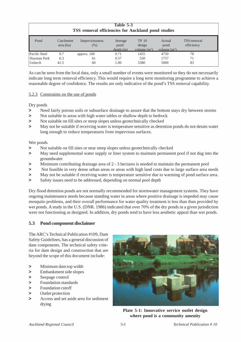
The ARC’s Technical Publication #109, DamSafety Guidelines, has a general discussion ofdam components. The technical safety crite-ria for dam design and construction that arebeyond the scope of this document include:
> Minimum dam top width> Embankment side slopes> Seepage control> Foundation standards> Foundation cutoff> Outlet protection> Access and set aside area for sediment
drying
Plate 5-1: Innovative service outlet designwhere pond is a community amenity

5-4Auckland Regional Council Technical Publication # 10
Two issues that will be discussed in this Chapter are minimum spillway capacity, as spillway design will affectthe duration of detention and therefore stormwater quantity and quality control, and pond forebay areas andcapacity. These will be discussed in the Design Procedure section.
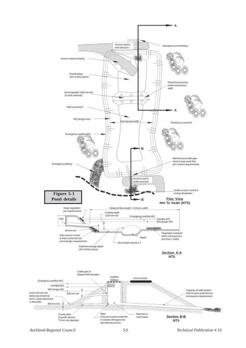
A typical wet pond is shown in Figure 5-1.
5.4 Design approach
5.4.1 Objectives
Water quantity objectives
Urbanisation has dramatic impacts on the amount of stormwater runoff that is generated from a catchment.Examples of the level of impact can be seen in the case studies chapter of the Low Impact Design Manualfor the Auckland Region (TP 124). On the three case studies, peak rates of discharge were increased from70 - 90 percent from pre-development to post-development for the two year storm and the total annualvolume of runoff increased approximately 300 percent. Ponds, when properly sized, can be a primary quan-tity control practice.
ARC criteria for water quantity control depend on the receiving environment. If the receiving environment isa piped stormwater reticulation system with adequate capacity for the increased runoff or tidal (either estua-rine or marine), then water quantity control is not an issue and a number of practices can be used to achievewater quality goals. If the receiving environment is a stream, then control of peak rates of runoff may be arequirement, and ponds become a primary option for controlling discharge rates.
ARC policy is to ensure that post-development peak discharges for both the 2 and 10 year storms remain attheir pre-development peak rates for those storms. The intent of peak discharge control of storms of twodifferent frequencies is to achieve benefits for a range of discharges. Controlling the peak rates for the 2 and10 year storms provides control of storms between those intervals and also will provide management for apercentage of peak flows from storms of greater magnitude (Maryland, 1982).
Where there are downstream flooding issues, peak discharges for the post development 100 year 1% AEPstorm event may need to be managed to ensure that downstream flood levels are not increased. Dependingon the catchment, the number of tributaries and the location of the project in a catchment, timing of flowdischarges may be an issue. If so, a catchment wide study may be necessary to ensure that downstreamflood risks are not increased. If there is no catchment-wide study, work done by Manuakau City Council andoverseas has indicated that limiting the peak discharge of the 100 year storm to not exceed 80% of the pre-development 100 year storm will reduce downstream flood increase concerns. The 80% peak discharge ratereduces potential for coincidence of elevated flow downstream by extended release of the flows. The ARCwill accept this approach as an alternative to a catchment wide study.
Water quality objectives
Water quality objectives aim for 75% removal of TSS. Ponds are not as appropriate for dissolved contami-nants (refer to Chapter 4 for land use versus contaminants generated). They are more appropriate wheresedimentation can achieve stated goals.
Where possible, water quality ponds ponds need a bypass for larger flows. Because all flows travel throughthe pond, water quality performance during larger events will be reduced as first flush contaminants arecarried through it. Ideally, larger flows should bypass the pond in order to avoid a drop in water qualityperformance, albeit at the expense of its ability to provide peak flow reduction for larger storms.
In those situations, it may be best to use a treatment train approach to stormwater where other practicesprovide primary water quality treatment while the pond is primarily used for water quantity control. Althoughdesirable, this approach may not always be possible due to site constraints.
5-5Auckland Regional Council Technical Publication # 10
Access RoadOverflowSpillway
Outlet pipe atWetpool WS elevation
Emergency overflow WS
Overflow WS
WQ design WS
300 mm min
450 mm min
Invert 150 mm minbelow top of internalberm. Lower placementis desirable.
Gravity drain(if grade allows)75 mm min diameter
Valve(may be located inside MHor outside with approvedoperational access)
Manhole orcatch basin Section B-B
NTS
Capacity of outlet systemsized to pass peak flow forconveyance requirements
Section A-ANTS
Wetpond flow length = 3 (min) x width
Inlet
Slope vegetationper requirements
60 mm min.
Inlet erosion control& slope protection perpond design requirements
Sediment storage depth15% of WQ volume
Bund slope may be 2:1
Keyed
Vegetation requiredwhen normal pool isless than 1 metre
Forebay depth1200 mm min Emergency overflow WS
Overflow WSWQ design WS
Plan ViewNot To Scale (NTS)
B
B
Access road tooutlet structure
Emergency spillway
Outlet erosion control &energy dissipation
Manhole and outlet pipesized to pass peak flowper consent requirements
Planting as requiredNormal pool width
A
A
Extend bund acrossentire normal poolwidth
Inlet pipe to pond forebayAccess road toinlet structure
Access ramp to forebay
Pond forebay15% of WQ volume
Bund topwidth 1500 mm min.(if earth material)
Main pond area
WQ design level
Emergency overflow WS
Figure 5-1Pond details
5-6Auckland Regional Council Technical Publication # 10
There is a direct linkage between water quality treatment and flow control. If catchment considerationsnecessitate peak controls, it is recommended that 50% of the calculated water quality volume be placed asdead storage while 50% of the water quality volume can be live storage and released as part of the 34.5 mmrainfall capture and release requirement (as discussed in the next section). This water quality credit can onlybe provided when storage and release of the runoff from the 34.5 mm rainfall is required. The permanentstorage will reduce flow velocities entering the pond, while the extended detention will facilitate (in additionto the wet pool) settlement of particulates. If there is no requirement for either extended detention or peakcontrol, the entire water quality volume can be stored within the permanent pool level.
Channel protection objectives
Urban development has the effect of increasing the frequency and magnitude of floods, particularly duringfrequent small storm events. As a consequence streams can suffer an increase in erosion, as channelsenlarge to cope with the increased storm response. The objective of criteria related to channel protection isto maintain or improve the in-stream channel stability to protect ecological values of the stream and reducesedimentation downstream.
A study (BECA, 2001) done for the ARC recommends that the pond outlet should be designed to convey thevolume generated by the first 30 mm of runoff over the total catchment area and release that volume over a24 hour period from a 2 year frequency storm event. However, because more extensive impervious surfacesupstream require more storage to achieve the discharge target, the ARC requires the runoff from a rainfallevent of 34.5 mm to be stored and released over a 24 hour period to minimise potential for stream channelerosion.
This provision is in addition to normal stormwater quality and flow attenuation requirements. However, byusing extended detention for some of the stormwater quality treatment rather than a full wet pond, thetreatment and erosion attenuation volumes may be partially combined, reducing total pond volume. Section5.5 summarises all the relevant design requirements.
Ponds in series
The ARC does not generally recommend the use of ponds in series instead of a single pond with an equiva-lent surface area. If the single pond were divided into two ponds in series then each of the two ponds wouldhave approximately 1/2 of the surface area of the single one. Each pond then has half the detention time, sothe first pond takes out the coarser sediment. The flow is then remixed in the channel between ponds, and thesecond pond is too small to take out the finer fractions. Therefore ponds in series may be less efficient thansingle large ponds of equivalent volume.
However, sometimes site constraints make it necessary to use two or more treatment ponds in series ratherthan one larger single pond. To offset the reduction in sediment removal, where two or more ponds in seriesare necessary they should be sized at 1.2 times the volume specified in this document for a single pond.Where there are no specific site constraints, a single pond is preferred.
5.4.2 Preferences
Preferences for wetlands versus ponds
While TP 10 is a ‘toolbox’ of available stormwater management practices, constructed wetlands are pre-ferred to open water ponds because they provide better filtration of contaminants, including dissolved onesdue to densities of wetland plants, incorporation of contaminants in soils, adsorption, plant uptake, and biologi-cal microbial decomposition (more in depth discussion in Chapter 6). In addition, wetlands, being shallowwater bodies do not have the safety issues associated with deeper water ponds. For these reasons, the ARChas a preference for shallow wetland ponds where ponds are used.
5-7Auckland Regional Council Technical Publication # 10
On-line versus off-line
As clearly stated in the Air, Land, and Water Plan the ARC has preference for ‘off-line’ placement of pondsrather than ‘on-line’. Off-line ponds are considered to be those ponds not physically located in perennialwatercourses. They can be in gullies or upland areas. On-line ponds are located on streams having perennialflows and their impact to the stream itself can be significant. On-line ponds alter geomorphic and biologicalcharacter of streams and these alterations may adversely impact on the streams natural character andfunction.
However, while off-line ponds are a preference, it is not a hard and fast rule. Within the Metropolitan UrbanLimits (see Auckland Regional Policy Maps) on-line ponds may be the only option to provide downstreambenefits if there is already a high level of development that exists in a catchment. In those areas, on-lineponds would have to be considered on a case-by-case basis to determine suitability.
There may be mitigation requirements placed on on-line ponds to compensate for the loss of stream habitatwhen an on-line pond is accepted for a specific location.
Dry ponds versus wet ponds
Dry ponds are not normally recommended. They need more maintenance and have a lower water qualityperformance than wet ponds. In terms of preference when ponds are the selected options, constructedwetlands are a first choice, followed by wet ponds, and finally dry ponds.
Maintenance responsibility
Maintenance issues will be discussed later in this Chapter but the issue of ensuring an entity is responsible formaintenance must be considered as an issue to determine whether ponds are applicable in a given situation.Ponds are expensive and require routine and non-routine maintenance to ensure proper long-term perform-ance or failure of the pond system can occur. While a swale can fill in or a sand filter clog, pond failure canhave significant effects, such as property damage and potential loss of life. Ponds must therefore be re-garded as small dams, and evaluated in the context of best practice for dam operation. If maintenanceresponsibility cannot be defined during the design phase, ponds should not be selected for a given site.
5.4.3 Safety features
Depth
Deeper ponds can be attractive to children who like open water. Historically, ponds have been 1 - 3 metresdeep, sometimes over anyone’s head. Stormwater ponds should not be deeper than 2 metres, if at all possible.If water quality volume requirements and site limitations limit pond area, then use a wetland and extendeddetention live storage to achieve the water quality volume.
Benches
A reverse slope bench or slope break should be provided 300 mm above the normal standing water pool(where there is a normal pool) for safety purposes. All ponds should also have a shallow bench 300 mm deepthat extends at least three metres from the shoreline, before sloping down to the pond floor. This shallowbench will facilitate the growth of emergent wetland plants and also act as a safety feature.
In addition to the benches, the steepness of the pond slope down to the invert of the pond should not exceed4 horizontal to 1 vertical. Steeper slopes will make it very difficult for someone who is in the pond to get outof it.

5-8Auckland Regional Council Technical Publication # 10
The reverse slope above the waterline has atleast three functions. It:
1. Reduces erosion by rilling that normallywould be expected on longer slopes.
2. Intercept particulates traveling down theslope and conveys them to the pond inflow.
3. Provides an additional safety feature toreduce the potential for children running orriding uncontrolled down the slope andfalling into the pond.
Fences
The ARC does not require fencing of ponds,because we consider that use of natural fea-tures such as reverse benching, densebankplanting, and wetlands buffers (which consists of a dense stand of vegetation) will provide a similar level ofprotection. Territorial authorities retain their own discretion about fencing.
5.4.4 Aesthetics
Aesthetics must be considered as an essential pond design component. Ponds can be a site amenity ifproperly designed and landscaped or can be a scar on the landscape. The developer and designer shouldconsider the pond as if they themselves were to be living in the development. Small items can have a biginfluence on the livability of a given area to residents and the best time to consider the issue is during thedesign phase. There is a greater discussion of landscaping in Chapter 14.
5.5 Design procedure
5.5.1 Approach
Pond sizes are determined to remove 75% of the incoming sediment load on a long-term basis. The develop-ment of this sizing rationale and size versus performance curves are presented in an earlier report (ARC, TP4) whose results are incorporated into this manual.
Pond design tasks, in order, include the following:
1. Determine the need for water quantity control. In normal situations if it is required, that requirementwill be to limit post-development peak discharges for the 2 and 10 year frequency storms to their pre-development peak discharge release rates.
If downstream flooding is documented, the post-development 100 year storm peak discharge rate mayalso need to be limited. In this case, a catchment analysis may be necessary or, as an option to thecatchment analysis, limiting the 100 year peak discharge to 80% of the the pre-development releaserate.
2. Protect channel form in receiving environment. If the discharge enters a perennial natural streamchannel, its channel will need to be protected from erosion.In such cases the runoff from a rainfallevent of 34.5 mm shall be stored and released over a 24 hour period.
3. Determine the need for water quality control. Calculate the water quality volume (1/3 of the 2 year-24hour rainfall, as shown in Chapter 3) that needs to be treated when detention is required, and provide
Plate 5-2: Example of a safety bench (abovewater) in conjunction with a shallow bench (note:normal pool level has been lowered to allow for
planting of shallow bench)

5-9Auckland Regional Council Technical Publication # 10
at least 50% of that volume as permanent pond storage. The other 50% stores and releases runofffrom the 34.5 mm of rainfall over a 24 hour period.
A TP 108 analysis is needed for up to five rainfall events including the 2 year, 10 year, possibly 100 year, 34.5mm rainfall, and 1/3 of the 2 year rainfall. The 2, 10, and 100 year events must be done for both pre- and post-development while the 34.5 mm (erosion protection) and 1/3 of the 2 year rainfall (water quality treatment)events are based on the post-development condition.
5.5.2 Spillways and outlet capacity
There are two primary outlets from a pond: the service outlet and the emergency outlet. They will be dis-cussed in the context of their sizing. Figure 5-2 illustrates the various outlet elements and components. Theterms detailed in the figure are those used in the Hydraulic Flow discussion of this chapter.
Service outlet
The service outlet should be designed to at least accommodate the flows from the primary drainage systementering the pond. The service outlet will normally convey the flow from the extended detention orifice, the2 year storm and the 10 year storm. In addition, the service outlet should also have a gate valve at the invertof the normal pool to allow for drainage of the pond during maintenance.
When an extended detention orifice is required, that orifice shall not be less than 50 mm in diameter (or 50mm wide if a slot). If calculations indicate an orifice (or slot) of smaller size, the 50 mm shall be used andattention must be given to implementation of protective measures such as cover plate or other means, toprevent blockage of the orifice. It is important to consider blockage on all outlet devices but the extendeddetention outlet will be susceptable to blockage unless specifically designed for.
Emergency spillway
The emergency spillway will convey flows beyond the service spillway’s capacity. It should be designed toconvey at least the 100 year storm with a freeboard of at least 300 mm.
The emergency spillway should be located in natural ground and not placed on fill material unless it isarmoured to prevent scour of the embankment. Operating velocities must be calculated for spillways innatural ground in order to determine the need for additional armouring. If the emergency spillway is placed onfill, the embankment should be constructed higher than the final design to allow for settlement.
In situations where embankment failure may lead to loss of life or extreme property damage (see TP 109,Dam Safefy Guidelines, Hazard Analysis), the emergency spillway must be able to:
> Pass an extreme flood, which may be the Probable Maximum Flood (PMF), with no freeboard (after
Figure 5-2Schematic pond levels
Minimum Freeboard Top ofEmbankment
Qvhv
hiv
hiii
hii
hi
Qiv
Qiii
Qii
Qi
Drainage OutletSediment Storage
ExtendedDetention
Water QualityVolume
Extreme Flood Level100 Year Flood Level
Emergency Outlet Level
Service Outlet Level
Extended DetentionOutlet Level
Emergency Outlet
PondEmbankment
Extended DetentionOutlet
Service Outlet
5-10Auckland Regional Council Technical Publication # 10
post-construction settlement) and with the service outlet blocked. The PMF is defined in TP 109 as thelargest probable flood event that could occur at the site, or the theoretical upper limit to flood magni-tude. The extreme flood (Q
v) is defined as detailed in NIWA Science and Technology Series No. 19,
“A Guide to Probable Maximum Precipitation in New Zealand”, June 1995. For high risk dams asdefined in Tp 109, discussion with the ARC is essential to determine the needed factor of safety.
> Pass the full Qiv (the 1% AEP event flow) assuming the service spillway is blocked with at least 0.5
metres of freeboard (after construction settlement).
5.5.3 Forebay
A forebay must be provided for all wet ponds. The sediment forebay is intended to capture only coarsesediments and is the location where most frequent sediment clean will be needed because coarser particlescomprise the highest proportion of incoming sedments in terms of total volume. Thus the more frequentcleanout of the forebay area.
The forebay should meet the following criteria:
1. The volume of the forebay should be at least 15 % of the water quality volume (or 30% of the adjustedvolume when extended detention is required). It should be cleaned out when filled in to about 50% ofits design volume.
2. Flow velocities from the forebay during the 1 in 10 year storm must be less than 0.25 m/s, in order toavoid resuspension of sediment. In some cases this may necessitate more than the minimum forebayvolume. The recommended depth of the forebay is 1 metre or more, to reduce velocities.
5.5.4 Hydraulic flow characteristics
1. Calculate the water quality volume to be treated using 1/3 of the 2 year-24 hour rainfall event andseparately calculated for pervious and impervious areas (as in Chapter 3, Section 3.5). Time of con-centration should be at least 0.17 hours.
2. Take a minimum of 50% of that volume for normal pool (dead) storage (when detention is required).
3. Use the 34.5 mm rainfall for the TP 108 analysis to determine the depth of runoff that is to be storedand released over a 24 hour period.
4. Conservatively assume that the entire extended detention volume is in the pond at one time eventhough this will not actually be the case since the outlet orifice will be sized to release this volume overa 24 hour duration.
> Use an elevation - storage table to estimate the elevation required to store the full extended deten-tion volume
> Calculate the average release rate (equal to the volume/duration) = Qavg
> At the full extended detention design elevation, the maximum release rate is assumed to be Qmax
=2(Q
avg)
> Calculate the required low flow orifice size: Qi = 0.62A(2gh
i)0.5 by trialing various orifice sizes.
> hi = elevation difference = the elevation at extended detention - the elevation at normal pool + d/2.
Other devices may be suitable for extended detention design, and all are based on a similar approachto the orifice opening approach. Those designs can include:

5-11Auckland Regional Council Technical Publication # 10
> Multiple orifices at the same elevation (n orifices, A area each) Qi = n 0.62A(2gh
i)0.5
> Vertical slot extending to water surface (width w) Qi = 1.8 w h
i3/2
> Vertically spaced orifices (situated h1,h
a,h
b from surface Q = 0.62A(2gh
1)0.5 +
of pond filled to the WQ 0.62A(2gha)0.5 +
volume. Each orifice area A) 0.62A(2ghb)0.5
> Pipe (area A) h = (1.5Qi2/2gA2) + h
f
where hf is pipe friction loss
A number of different outlet designs for extended detention are detailed in Figure 5-3.
5. 2 and 10 year stormwater management
Set the invert elevation of the 2 year release point at the extended detention water surface elevation(based on the elevation - storage table mentioned in step 4)
The service outlet may consist of a drop inlet structure, a broad crested weir, a cascade weir or a weirleading to an open channel. As peak control requirements call for both 2 and 10 year frequency stormsto be controlled, the discharge is clearly defined in terms of the following equations.
Figure 5-3Types of extended detention outlets
Permanent pool level
Service outlet level
Barrel
Reversesloping
pipe
hi
Service outlet level
Service outlet level
hi
hi
hi
Barrel
Permanent pool level
Orifice
ScreenLargescreen
Variable water level
Waterqualityvolume
Orifice
Permanent pool level
Sharp-crestedweir level
Permanent pool level
Screen
Slot
5-12Auckland Regional Council Technical Publication # 10
Drop inlet
For moderate flows, the top of the drop shaft acts as a circular sharp weir. For a circular drop inlet, theenergy head above the weir lip, (h
ii) can be used to calculate the flow according to:
Qii = 3.6πR h
ii3/2 (SI units)
Where R is the radius of the inlet.
For a box weir:
Qii = 7.0wh
ii3/2
where w is the length of the side of the square box, on the inside.
These equations apply only for hii/R ≤≤≤≤≤ 0.45 (or, for a box inlet, h
ii/w ≤ ≤ ≤ ≤ ≤ 0.45). For h
ii/R > 0.45, the weir
becomes partly submerged, and for hii/R > 1 the inlet is fully submerged and the flow resistance is
equal to the inlet resistance of a pipe, typically:
hii = k(v2/2g)
where v is the velocity at flow Qii and k is typically 0.5 to 1.0, depending on the details of
the inlet.
For a circular inlet:
v = Qii/πR2
Starting with the design flow and the chosen pipe radius, the head (hii) can be found by using the
appropriate formula for the hii/R value. If this head is higher than desired, a large outlet can be used.
Aeration of the flow over the weir should be considered if the flows are so high that inadequateventilation may cause damage to the drop structure. In general, adequate ventilation will be providedby appropriate sizing of the outlet pipes. It is recommended that the outlet pipe be sized so that whenthe emergency spillway is operating at maximum flow (Q
v), the outlet discharges at 75% full. Standard
pipe friction and pipe outlet loss calculations can be performed to determine the required outlet size(USBR, 1977).
The entry to the outlet should be protected by a screen or grid cage to collect debris.
Broad crested weir
In this case, a weir narrower than the emergency weir is used. The weir could be situated away fromthe emergency weir, or if sufficient erosion protection is provided, in a lowered section of the emer-gency spillway.
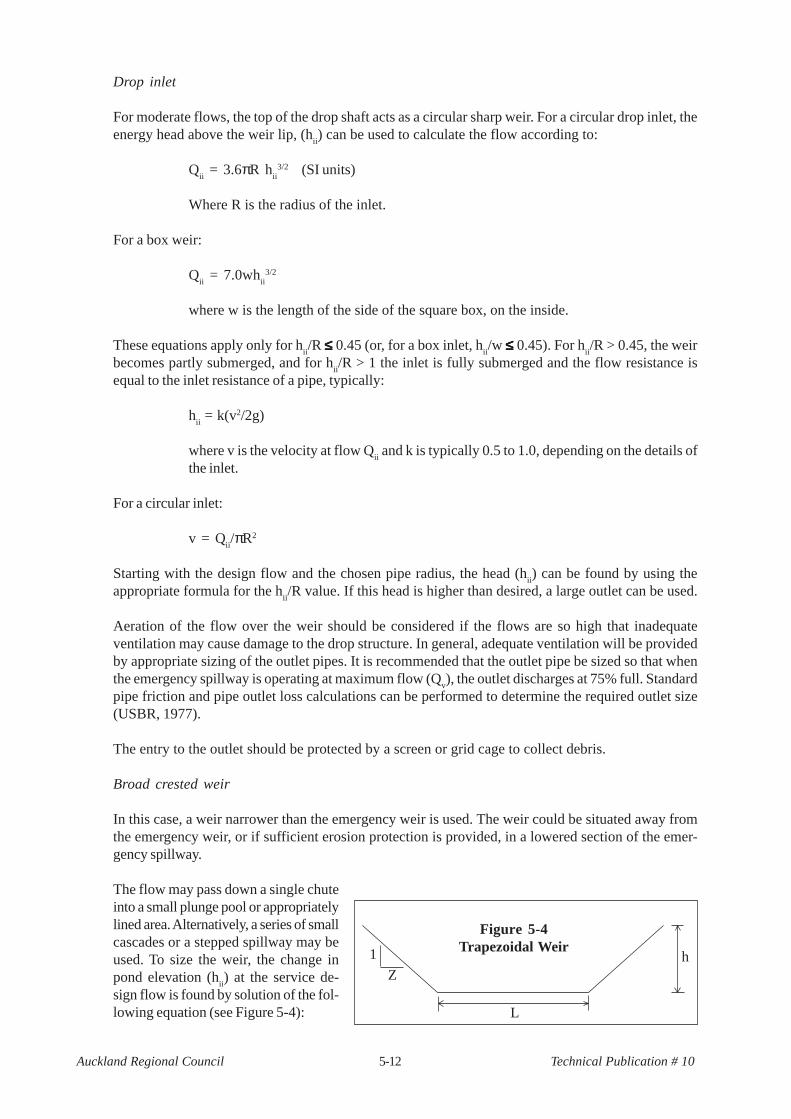
The flow may pass down a single chuteinto a small plunge pool or appropriatelylined area. Alternatively, a series of smallcascades or a stepped spillway may beused. To size the weir, the change inpond elevation (h
ii) at the service de-
sign flow is found by solution of the fol-lowing equation (see Figure 5-4):
h1
Z
L
Figure 5-4Trapezoidal Weir
5-13Auckland Regional Council Technical Publication # 10
Qii = 0.57(2g)1/2(2/3Lh3/2 + 8/15zh5/2)
As an approximation, the following formula may be be used for a broad-crested weir:
Qii = 1.7 L h
ii3/2
Weir with channel
This design will be useful for shallower ponds, where the channel can be easily constructed by makinga cut in the embankment.
The outflow is controlled by the weir. Appropriate texts may be consulted for refined weir calculations,but the following may be used as an approximation for a sharp-crested weir:
Qii = 1.8Lh
ii3/2
where Qii is the service design flow, h
ii is the head over the weir when the emergency spillway starts
operation and L is the length of the weir. The outlet channel should be sufficiently large that the waterlevel is below the water level (h
ii) at the service design flow (to avoid backwater effects). The channel
may require covering for safety reasons.
6. Emergency spillway design
The emergency spillway section is normally designed as a trapezoidal channel whose sizing is basedon trial and error to the following equation:
Q = 0.57(2g)1/2(2/3Lh3/2 + 8/15Zh5/2)
where:Q = discharge through the spillwayL = horizontal bottom width of the spillwayh = depth of flow at design flowZ = horizontal/vertical side slope (recommended to be 3)
5.5.5 Designs to avoid short-circuiting
Dead zones and short-circuiting are undesirable because they reduce effective pond detention times. Theflow path length must be at least twice the pond width, and preferably three times the width (but not muchgreater). The narrower the flow path, the greater the velocity and the less settling will occur . The designershould minimise dead zones and short-circuiting to improve the treatment performance of the pond.
5.5.6 Oil separation
Stormwater will, in most situations, contain oils and greases. Having an extended detention outlet similar tothe reverse sloping pipe shown in Figure 5-3 will allow water to be discharged from below the surface andencourage volatilisation of the hydrocarbons on the surface.
5.5.7 Debris screens
Screens are used to trap rubbish and organic debris, which is unsightly, especially if trapped in vegetation.Screens should be used to protect extended detention outlets from clogging. Screens may be installed at theinlet to the pond or at the outlet from the pond. Various outlets are detailed in Figure 5-3.
5-14Auckland Regional Council Technical Publication # 10
5.5.8 Ease of maintenance
Ease of maintenance must be considered as a site design component. Access to the stormwater manage-ment pond or wetland must be provided for in the design, and land area adjacent to the pond must be set asidefor drying out of sediments removed from the pond when maintenance is performed. The land set aside forpond maintenance must be sized as follows:
1. The set aside area shall accommodate at least 10 percent of the stormwater management pond vol-ume at a maximum depth of one metre, and
2. The slope of the set aside area shall not exceed 5 percent, and3. The area and slope set aside may be modified if an alternative area or method of disposal is approved
on a case by case basis.
5.6 Pond and site design
5.6.1 Pond shape
The design of pond shape should consider engineering constraints, design parameters to achieve treatment,and the existing topography. For a given catchment the design parameters include water volume, surfacearea, depth, water flow velocity and detention period. In addition, it is recommended that the length to widthratio be 3 horizontal to 1 vertical or greater to facilitate sedimentation. These parameters should be consid-ered in light of the existing topography. Generally, a pond will look more natural and aesthetically pleasing ifit is fitted into existing contours.
5.6.2 Pond contours
Pond contour profiles are critical to the design of a pond: they determine available storage, the range of plantsthat can be grown and the movement of water through the pond. The safety features of shallow slopes andreverse slopes will help provide areas suitable for a variety of plants.
5.6.3 Edge form
Edge form influences the appearance of a pond, increases the range of plant and wildlife habitats and hasimplications for pond maintenance. Edges can include sloping margins where water level fluctuations causegreater areas of wet soils. Generally, sloping margins require a more sophisticated management approach toensure growth of plants. Areas of gradually varied wetness should be identified and specific planting strate-gies should be developed for these areas. Such gradually sloping areas can appear a more natural part of thelandscape than steep banks, and they provide opportunities for a greater range of plants and habitat.
5.6.4 Islands
Islands, properly located, can be used to manipulate flow characteristics, to increase the distance that watertravels and to help segregate first flush inflow from later flows within a storm event. They also increase theextent of planted margin and can provide a wildlife habitat that offers some protection from domestic animalsor people, as well as offering additional aesthetic appeal.
5.7 Landscaping
Design of a stormwater pond system should ensure that the pond fits in with the surrounding landscape.General landscape design principles will apply. The area should develop a strong and definite theme orcharacter. This might be generated from particular trees, or views from the site, topographical features, orthe cultural character of the surrounding neighbourhood. The landscape design for the area will provide asetting for the pond so that the pond will appear a natural component of the overall setting.

5-15Auckland Regional Council Technical Publication # 10
5.8 Construction
In addition to the information provided in this chapter, dam builders and owners should refer to TP 109, DamSafety Guidelines has information on monitoring of dams during and post- construction.
Most of the information on wet systems is directed towards ponds where the normal pool of water is establishedby the construction of an embankment. Excavated ponds typically do not have the same safety concernsrelated to embankment failure.
When constructing wet ponds, it is very important to regularly inspect for seepage through the embankment.Detention ponds with a normal pool of water develop a zone of saturation through the embankment, whichcan increase failure potential in the future.Concerns regarding this zone of saturation (frequently detailed onplans as the area below the phreatic line) are alleviated by good quality control during construction.
The risk of a potential hazard is reduced by requiring, during design, safety features in the embankmentwhich reduce the movement of water through the embankment. These safety features include anti-seepcollars, diaphragms, core trenches, and clay cores. These features are not visible once construction iscompleted. Their construction and quality of construction must be verified by the inspector during theirinstallation. Failure to inspect these features at critical times may result in embankment failure in the future.
Detention or retention practices which are normally dry do not develop a zone of saturation (which resultsfrom standing water), and internal water seepage is not a critical concern.
5.8.1 Important inspection aspects related to design
When certain site conditions are encountered or where the design has an unusual aspect, it is important tokeep in regular communication with the consent agency (ARC, TA) to avoid some common mistakes. Examplesof items which should be discussed include:
1. Encountering sandy soils when building a wet pond designed with a normal pool of water when theplan does not specify a pond liner.
2. Stormwater inlets too near the intended outfall, thereby creating a short-circuit flow path. While thismay be acceptable from a stormwater quantity perspective, the short circuiting will reduce treatmentand lessen water quality benefits.
3. Steep slopes into the pond with no slope breaks (benches) can increase the hazard potential anderosion of side slopes.
4. Failure to include on the plans essential components normally associated with ponds, such as anti-seep collars, trash protection for low flow pipes, service and emergency spillways.
5. Failure to include a draw down mechanism in wet ponds. Wet detention ponds should have a meansto draw the water level down should draining the pond become necessary. From an inspector'sviewpoint, a wet detention pond without a drawdown mechanism should be brought to the attentionof the consent agency. Where groundwater provides the permanent water pool, a drawdown mecha-nism won't be available. The inspector should know the expected or design ground water elevationsat a site, especially the seasonal high level. This information should be on the approved plans.
Refer to the checklist at the end of the chapter.
5.8.2 Important inspection aspects related to construction
This section highlights important things to inspect during the construction of ponds. At the end of the chapteris an example of a Sediment/stormwater management pond construction checklist. This checklist, adapted asneeded, should be used by inspectors during construction of stormwater management ponds.
1. A major cause of pond failure is soil piping - water traveling along the outside of the service spillway.It generally occurs along a metal or concrete pipe where water which is under pressure from the
5-16Auckland Regional Council Technical Publication # 10
depth of water in the pond causes erosion of soil adjacent to the pipe. Erosion of this material causesthe pond embankment to be weakened at that point and failure of the embankment results. Thisfailure is much more likely to occur in wet detention ponds than in normally dry ones because theyhave a permanent pool of water next to the embankment. Water will soak into the embankment andseek a lower elevation. Failure potential can be prevented by proper installation of anti-seep collarsor diaphragms, in conjunction with proper compaction of soils adjacent to the service spillway andcollars or diaphragms.
2. The general minimum standards for construction work also apply to the construction of stormwaterponds. Does the construction comply with local material and equipment requirements for earthwork,concrete, other masonry, reinforcing steel, pipe, water gates, metal, and woodwork?
3. Are interior side slopes no steeper than 3:1(horizontal to vertical) and exterior side slopes no steeperthan 2:1? The reason most stormwater embankment ponds remain stable is that the mass of earth inthe embankment is heavy enough to prevent slippage of material caused by water pressure on theupstream slope. Steep side slopes are not only more dangerous to the general public, but they alsoreduce the total mass of earth material in the embankment. This can increase the potential forembankment failure.
4. Are elevations relatively accurate and according to the approved plans? An inspector should carrya simple Locke level to determine whether a given location is at proper elevation. The invert elevationof a service spillway must be lower than the elevation of the pond embankment or trouble can beexpected. A Locke level provides a quick, moderately accurate, means to verify field implementation.
5. Are inlet and outlet areas stabilised to prevent erosion? Relying only on vegetative practices forstabilisation is generally inadequate since it takes time for the vegetation to become well established.Some form of additional stabilisation technique is generally necessary to protect soil until vegetationis established. This can include erosion control matting, riprap, gabions, and the like.
6. Are safety features provided? These may include the shallow bench surrounding the pond edge,barrier plantings to discourage approach by children, and/or fencing where required.
7. A sequence of construction must be established and followed. It is just as important that constructionbe done in the correct order as it is to have good quality construction. The sequence of constructionincludes preconstruction meetings, temporary erosion and sediment control, core trench, and so on.An example of a typical pond sequence of construction is presented at the end of the chapter.
8. Upon completion of construction, a final inspection should be performed. This inspection provideswritten documentation to the developer/contractor of the satisfactory completion of the facility. De-pending on regional or local council requirements, this inspection augments the submission of an As-built plan.
5.8.3 As-built plans
Where consent conditions require, there may be a requirement for an As-Built Plan to verify that constructionwas done in accordance with the approved consent.
As-built plans should detail:
1. A section along the crest of the dam2. A cross-section of the emergency spillway3. A section along the centreline of the emergency spillway4. A section along the centreline of the principal spillway extending at least 20 metres downstream of
the fill5. The elevation of the principal spillway crest6. The elevation of the principal spillway conduit invert (inlet and outlet)7. The diameter, length, thickness and type of material for the riser8. The diameter, length and type of material of the conduit9. The size and type of anti-vortex and trash rack device and its elevations in relation to the principal
spillway crest10. The number, size, and location of the anti-seep collars11. The diameter and size of any low stage orifices or drain pipes
5-17Auckland Regional Council Technical Publication # 10
12. The length, width, and depth of contours of the pond area so that design volumes can be verified13. Any erosion control measures at inflow and outflow points14. Notes and measurements to show that any special design features were met15. Statement on seeding and fencing (as appropriate)16. Notes on site clean up and disposal17. Sign and date check notes to include statement that practice meets or exceeds plans and
specifications
5.9 Pond safety
The most important concern of stormwater management detention and retention ponds is safety. Failure toact in some situations may cause structural failure. Inspections must be made at least annually to ensure thesafety of a stormwater pond. If there is any concern that the facility is unsafe, the pond owner must seekadvice from a dam safety expert. Failure to take action when confronted with a potential problem canincrease liability if a failure occurs.
Complete failures of stormwater management ponds generally do not occur overnight. They start as smallproblems and increase gradually, hence the importance of regular maintenance.
Ponds are unique among stormwater practices. If filtration, biofiltration, or infiltration practices fail or clog,their reduced performance generally will not result in downstream safety concerns. Ponds provide effectivewater quality performance, but that performance is gained at the cost of increased safety concerns. Theymust be designed correctly, built satisfactorily and actively maintained. A failure in any one of these threeaspects of ponds could result in significant problems. Ponds are a valuable tool in controlling stormwaterrunoff, but care must be taken to ensure their long term effectiveness.
5.10 Operation and maintenance
In addition to the information provided in this Chapter, dam builders and owners should refer to TP 109, DamSafety Guidelines for information on monitoring of dams during and post - construction.
5.10.1 Aesthetic and functional maintenance
Maintenance falls into a number of different categories, but the two main areas are:
> Aesthetic/nuisance maintenance and> Functional maintenance.
These two areas can overlap at times. They are mutually and equally important. Functional maintenanceincludes routine (preventive) and corrective maintenance and is important for performance and safety reasons.Aesthetic maintenance is important primarily for public acceptance of stormwater facilities, and because itmay also reduce needed functional maintenance activities.
Both forms of maintenance are needed and both must be combined into an overall stormwater managementsystem maintenance program. Both forms of maintenance are included in the checklists in the back of thisChapter.
Aesthetic maintenance
Aesthetic maintenance primarily enhances the visual appearance and appeal of a stormwater pond. Anattractive stormwater pond will more easily become an integral part of a community. Aesthetic maintenanceis obviously more important for those ponds that are very visible. The following activities can be included inan aesthetic maintenance program:

5-18Auckland Regional Council Technical Publication # 10
> Graffiti removal
The timely removal of graffiti will improve the appearance of a stormwater pond. Timely removal willalso tend to discourage further graffiti or other acts of vandalism.
> Grass trimming
Trimming of grass around fences, outlet structures, hiker/biker paths, and structures will provide a moreattractive appearance to the general public. As much as possible, the design of stormwater ponds shouldincorporate natural landscaping elements which require less cutting and/or trimming. However, thereoften are areas where mowing will be necessary to maintain attractiveness.
> Control of weeds
In situations where vegetation has been established, undesirable plants can be expected. These undesirableplants can adversely impact the aesthetics of a stormwater pond and send the wrong signals to the publicabout weed control. This can also apply to wet detention littoral zones, which may be invaded by unde-sirable aquatic plant species. These undesirable plants can be removed through mechanical or chemicalmeans. If chemicals are used, the chemical should be used as directed and according to territorial councilrequirements and left over chemicals disposed of properly.
> Miscellaneous details
Careful and frequent attention to performing maintenance tasks such as painting, tree pruning, leaf collection,debris removal, and grass cutting (where intended) will allow a stormwater management pond to maintain anattractive appearance and help maintain its functional integrity.
Functional maintenance
Functional maintenance is necessary to keep a stormwater management system operational at all times. Ithas two components:
> Preventive maintenance> Corrective maintenance
Preventive maintenance
Preventive maintenance is done on a regular basis as detailed in the checklists contained at the end of thischapter. Tasks include upkeep of any moving parts, such as outlet drain valves or hinges for grates ormaintenance of locks. It can also include maintenance of vegetative cover to prevent erosion. Examplesof preventive maintenance include:
1. Grass mowing
Actual mowing requirements at a pond should be tailored to the specific site conditions and grasstype.
2. Grass maintenance
Grass areas require limited periodic fertilising and soil conditioning in order to maintain healthy growth.Provisions may have to be made to reseed and re-establish grass cover in areas damaged by sedi-ment accumulation, stormwater flow or other causes.
5-19Auckland Regional Council Technical Publication # 10
3. Vegetative cover
Trees, shrubs, and other landscaping ground cover may require periodic maintenance, including fertilising,pruning, and weed pest control.
4. Trash and debris
A regularly scheduled program of debris and trash removal will reduce the potential for outlet struc-tures, trash racks, and other pond components from becoming clogged and inoperable during stormevents. In addition, removal of trash and debris will prevent possible damage to vegetated areas andeliminate potential mosquito breeding habitats. Disposal of debris and trash must comply with all localand regional control programmes. Only suitable disposal and recycling sites should be used.
5. Sediment removal and disposal
Accumulated sediments should be removed before they threaten the operation or storage volume ofa stormwater management pond. Disposal of sediments also must comply with local and regionalrequirements especially if they are contaminated. Only suitable disposal areas should be used.
6. Mechanical components
Valves, sluice gates, pumps, fence gates, locks and access hatches should remain functional at alltimes. Regularly scheduled maintenance should be performed in accordance with the manufacturers'recommendations. All mechanical components should be operated during each maintenance inspec-tion to assure continued performance.
7. Elimination of mosquito breeding habitats
The most effective mosquito control programme is one which eliminates potential breeding habitats,or, in the case of open water ponds, ensures that optimal conditions are maintained for the survival ofmosquito control organisms. Any stagnant pool of water can become a mosquito breeding area withina matter of days. Ponded water in open cans, tyres, and areas of sediment accumulations or groundsettlement can become mosquito breeding areas.
8. Pond maintenance programme
A maintenance programme for monitoring the overall performance of the stormwater management pondshould be established. Wet detention ponds are especially complex environments. They require a healthyaquatic ecosystem to provide maximum benefits and to minimise maintenance. It is important to remem-ber that potentially large problems can be avoided if preventive maintenance is done in a timely fashion.
Corrective maintenance
Corrective maintenance is required on an emergency or non-routine basis to correct problems and torestore the intended operation and safe function of the pond. Corrective maintenance is done on an as-required, not on a scheduled basis. Failure to promptly address a corrective maintenance problem mayjeopardise the performance and integrity of the pond. It may also present a potential safety problem tothose living by or below it. Corrective maintenance activities include:
1. Removal of debris and sediment
Sediment, debris, and trash which threaten the ability of the pond to store or convey water should beremoved immediately and properly disposed of in order to restore proper pond function. A blockedinlet or outlet means that stormwater will travel in an area that was not normally designed as a flowpath. In the case of an inlet, the stormwater could travel over a kerb onto a grassed area and scour
5-20Auckland Regional Council Technical Publication # 10
it. If the outlet is blocked, water will back up in the pond and may travel through the emergencyspillway. These areas are not designed for frequent flow and may become eroded. If sediments areclogging a pond component, the lack of an available disposal site should not delay removal of thesediments. Temporary arrangements should be made for handling the sediments until a more perma-nent arrangement is made.
2. Structural repairs
Repairs to any structural component of the pond should be made promptly. Equipment, materials, andpersonnel must be readily available to perform repairs on short notice. The immediate nature of therepairs depends on the type of damage and its effects on the safety and operation of the pond.Where structural damage has occurred, the design and conduct of repairs should be undertaken onlyby qualified personnel.
3. Dam, embankment and slope repairs
Damage to dams, embankments, and slopes must be repaired quickly. Typical problems includesettlement, scouring, cracking, sloughing, seepage and rilling. A common concern in embankmentswith outflow pipes through them is seepage around the outside of the barrel. This can also causemovement of embankment soils, which can weaken the embankment. Repairs need to be madepromptly. Other temporary activities may be needed, such as drawing down the water level in thepond in order to relieve pressure on a dam or embankment or facilitate repairs. Crack repair in aconcrete structure may necessitate draining the pond and cleaning before repair. If the pond is to bedewatered, pumps may be necessary if there is no drain valve.
4. Elimination of mosquito breeding areas
If neglected, a stormwater pond can become a mosquito breeding area, especially where normallydry ponds do not completely drain and dry out. Corrective action may be needed if a mosquitoproblem exists and the stormwater pond is the source of the problem. If mosquito control in a pondbecomes necessary, the preventive maintenance programme for mosquitoes should be re-evaluated,and more emphasis placed on control of mosquito breeding habitats.
5. Erosion repair
Vegetative cover is necessary to prevent soil loss, maintain the structural integrity of the pond andmaintain its contaminant removal benefits. Where a reseeding program has been ineffective, orwhere other factors have created erosive conditions (such as pedestrian traffic, concentrated flow orthe like), corrective steps should be taken to prevent further loss of soil and any subsequent danger tothe performance of the pond. Corrective action can include erosion control blankets, riprap, soddingor reduced flow through the area.
6. Fence repair
Fences can be damaged by any number of factors, including vandalism and storms. Timely repair willmaintain the security of the site.
7. Elimination of trees or woody vegetation
Woody vegetation can present problems for dams or embankments. The root system of woodyvegetation can undermine dam or embankment strength. If the vegetation dies and the root systemdecomposes, voids can be created in the dam or embankment which weaken the structure. Preventivemaintenance can avoid this problem. However, when preventive maintenance programmes aredeficient, steps must be taken to eliminate the problem. Vegetation, including root systems, must beremoved from dams or embankments and the excavated materials replaced with proper material at a

5-21Auckland Regional Council Technical Publication # 10
specified compaction (normally 95% of the soil’s maximum density).
8. General facility maintenance
In addition to the above elements of corrective maintenance, general corrective maintenance shouldaddress the overall pond and it's associated components. If algal growth becomes a problem forponds, steps must be taken to re-establish its original performance. Stormwater ponds can be verycomplex systems. They will work only as long as each individual element functions correctly. If onepond component is undergoing corrective maintenance, other components should be inspected at thesame time to see if they also need maintenance. This may yield cost savings if equipment is alreadyon site.
5.10.2 Other maintenance activities
Maintenance activities for dry and wet ponds have many similarities, but there also are some differences inthe types of maintenance that are needed. Dry detention systems have more lawn areas, that must bemowed at least once per year to prevent the growth of woody vegetation on the embankment. Monthly ormore frequent mowing is necessary if good turf grass cover is expected or desired.
Dry detention ponds frequently have pilot or low flow channels to convey smaller flows. Concrete pilotchannels may become undermined, and stone ones may become choked with vegetation and require chemi-cal treatment to reestablish flow conveyance ability. Maintenance efforts for pilot channels will be done onan "as needed" basis. Careful inspection of concrete pilot channels is essential, as their undermining willjeopardise its structural integrity.
Wet detention ponds, with their normal water pool, are effective at converting inorganic nitrogen to organicnitrogen. Consequently, this may create algal problems unless littoral zones are planted and maintained withaquatic vegetation. Wet detention ponds also commonly have forebays to remove heavier sediments. Forebaymaintenance is therefore an important issue for wet detention ponds, and must be considered. Frequency offorebay maintenance depends on the incoming contaminant load and the forebay size.
Both dry and wet detention ponds have the potential for debris clogging of inlet and outlet structures. Residentialcommunities generate a surprising amount of debris, while commercial facilities can expect debris of allsorts. Inspections for debris should be made on a monthly basis or after rain events to ensure that all compo-nents of the stormwater ponds are operating as required.
Coarser sediments can be expected to be found close to the pond inlet, with finer sediments expected to bedeposited closer to the pond outfall. The coarser sediments will occupy a greater volume and maintenanceschedules should include more frequent removal. Forebays can be more easily and more often cleaned outextending the storage life of the rest of the pond.
To remove sediment from a wet pond drain the water down to the lowest possible level, leaving a small poolof water to provide habitat if there is a desirable resident fish population. This avoids disturbing fines andcausing significant turbidity downstream. Sediments removed from the pond should be placed where theycan dry before final placement. Sediment control provisions must be included in maintenance costs, to preventdownstream increases in contaminant loadings or to prevent removed sediments from re-entering the pond.
Sediment removal from dry detention ponds is more straightforward. Since they are normally dry, sedimentscan be removed by an appropriate means and disposed of in one operation. Experience has shown that it iseasier and more effective to remove sediments when they are dry and cracked, and thereby more easilyseparated from the vegetation. Sediment control during maintenance is necessary to prevent rainfall mobilisingstockpiled materials or eroding exposed soils.
Erosion problems can occur with either dry or wet detention ponds. For the most part they start as smallproblems which, if uncorrected, can grow into large problems and possibly threaten the integrity of the

5-22Auckland Regional Council Technical Publication # 10
detention pond. Inspections to locate erosionproblems should be done at least annually orafter major storms. Evidence of significantfoot or bike traffic in areas where vegeta-tion has died indicate potential erosion areasin the future. These areas should be pro-tected from traffic or provided with a moreerosive resistant ground cover.
Periodic maintenance of structuralcomponents must be done to ensure their con-tinued operation. This includes inspectingany joints for possible leakage or seepage.Areas should also be checked for corrosion,valves should be manipulated and lubricatedwhen needed, and all moving parts inspectedfor wear and tear.
5.11 Case study
Case study is a residential site, 7.5 hectares in size, with no off-site drainage passing through it..Waitemata series silts and claysGentle site slopes of 2.5%Predevelopment land use pasture
Post-development land use residentialAverage lot size 470 m2
Number of lots 100
Downstream flooding is not an issue but the site drains into a stream so peak criteria is required for the 2 and10 year storms in addition to extended detention for channel protection and water quality requirements
TP 108 analysis provided the following information:
2 year rainfall = 70 mm/24 hours10 year rainfall = 130 mm/24 hours
5.11.1 Pre-development condition
CN pre-development = 74I
a = 5 mm
Channelisation factor = 1Catchment length = 0.17 kmCatchment slope = 0.04 m/mtc = 0.17 hrs. (minimum as per TP 108)
2 year storm peak flow rate = 0.389 m3/s, runoff depth = 27.39 mm, runoff volume = 2054 m3
10 year storm peak flow rate = 1.03 m3 /s, runoff depth = 72.93 mm, runoff volume = 5470 m3
5.11.2 Post-development condition
CN of pervious areas = 74CN of impervious areas = 98Percentage impervious cover = 67% (see Table 2-2a of TP 108)Average CN = 90
Plate 5-3: Outlet Structure Showing MultipleStorm

5-23Auckland Regional Council Technical Publication # 10
Ia = 1.65 mm
Channelisation factor = 0.6Average runoff factor = 90/(200-90) = 0.82Catchment length = 0.2 kmCatchment slope = 0.034 m/mtc = 0.17 hrs. (minimum as per TP 108)
2 year storm peak flow rate = 0.66 m3/s,Runoff depth - pervious areas = 27.4 mm, runoff volume - pervious areas = 678 m3
Runoff depth - impervious areas = 65.2 mm, runoff volume - impervious areas = 3275 m3
Total runoff volume = 3954 m3
10 year storm peak flow rate = 1.42 m3/s,Runoff depth - pervious areas = 72.9 mm, runoff volume - pervious areas = 1805 m3
Runoff depth - impervious areas = 125 mm, runoff volume - impervious areas = 6282 m3
Total runoff volume = 8087 m3
5.11.3 Water quality volume
The WQV is based on 1/3 of the 2-year rainfall depth of 70 mm, equalling 23.3 mm.
TP 108 calculations for the post-development catchment give:Runoff depth - pervious areas = 3.1 mm, runoff volume - pervious areas = 77 m3
Runoff depth - impervious areas = 19.1 mm, runoff volume - impervious areas = 959 m3
Total runoff volume = 1037 m3 = WQV
Since extended detention will be required as an overlay, the extended detention will provide 50% reduction inthe WQV that must be held as permanent standing water.Thus the required permanent WQV for this example is 518 m3.
The forebay volume should be at least 10% of the required WQV, or 52 of m3 storage.This storage is based on the adjusted water quality volume rather than the total volume. In addition, thevolume is increased by an additional 50% to allow for deposition.The total forebay volume requirement is therefore 78 m3.
5.11.4 Extended detention volume (EDV)
The EDV is based on 34.5 mm of rainfall.
TP 108 calculations for the post-development catchment give:Runoff depth - pervious areas = 7.3, runoff volume - pervious areas = 182 m3
Runoff depth - impervious areas = 30.0 mm, runoff volume - impervious areas = 1507 m3
Total runoff volume = 1689 m3 = EDV
5.11.5 Pond outlet design
The pond can now be sized, with knowledge of the site contours and the above volume requirements. Let ussuppose that, in this case, the pond chosen has the following storage volume/stage relationship:
5-24Auckland Regional Council Technical Publication # 10
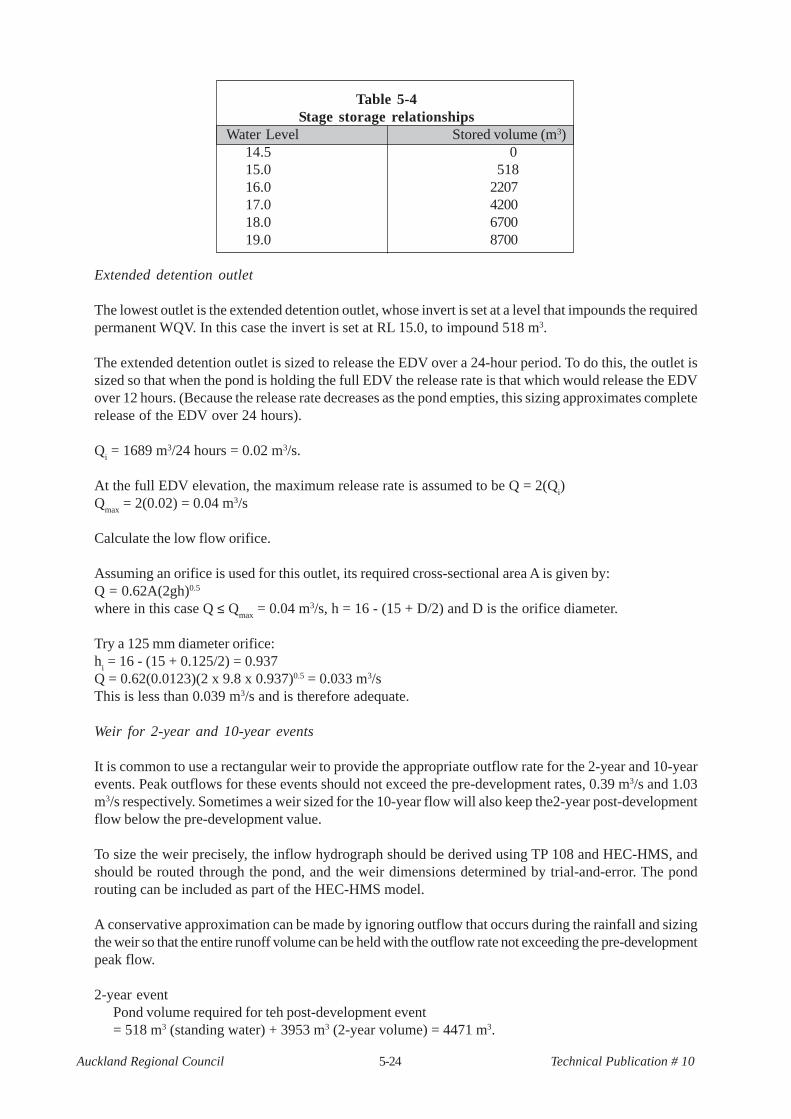
Table 5-4Stage storage relationships
Water Level Stored volume (m3) 14.5 0 15.0 518 16.0 2207 17.0 4200 18.0 6700 19.0 8700
Extended detention outlet
The lowest outlet is the extended detention outlet, whose invert is set at a level that impounds the requiredpermanent WQV. In this case the invert is set at RL 15.0, to impound 518 m3.
The extended detention outlet is sized to release the EDV over a 24-hour period. To do this, the outlet issized so that when the pond is holding the full EDV the release rate is that which would release the EDVover 12 hours. (Because the release rate decreases as the pond empties, this sizing approximates completerelease of the EDV over 24 hours).
Qi = 1689 m3/24 hours = 0.02 m3/s.
At the full EDV elevation, the maximum release rate is assumed to be Q = 2(Qi)
Qmax
= 2(0.02) = 0.04 m3/s
Calculate the low flow orifice.
Assuming an orifice is used for this outlet, its required cross-sectional area A is given by:Q = 0.62A(2gh)0.5
where in this case Q ≤ Qmax
= 0.04 m3/s, h = 16 - (15 + D/2) and D is the orifice diameter.
Try a 125 mm diameter orifice:h
i = 16 - (15 + 0.125/2) = 0.937
Q = 0.62(0.0123)(2 x 9.8 x 0.937)0.5 = 0.033 m3/sThis is less than 0.039 m3/s and is therefore adequate.
Weir for 2-year and 10-year events
It is common to use a rectangular weir to provide the appropriate outflow rate for the 2-year and 10-yearevents. Peak outflows for these events should not exceed the pre-development rates, 0.39 m3/s and 1.03m3/s respectively. Sometimes a weir sized for the 10-year flow will also keep the2-year post-developmentflow below the pre-development value.
To size the weir precisely, the inflow hydrograph should be derived using TP 108 and HEC-HMS, andshould be routed through the pond, and the weir dimensions determined by trial-and-error. The pondrouting can be included as part of the HEC-HMS model.
A conservative approximation can be made by ignoring outflow that occurs during the rainfall and sizingthe weir so that the entire runoff volume can be held with the outflow rate not exceeding the pre-developmentpeak flow.
2-year eventPond volume required for teh post-development event= 518 m3 (standing water) + 3953 m3 (2-year volume) = 4471 m3.

5-25Auckland Regional Council Technical Publication # 10
Ponded water level is therefore 17.12 m (by interpolation from stage / volume table)Weir invert level is the level at which the full EDV of 1689 m3 is impounded, RL 16.0 m.Ouflow from extended detention orifice Q
i = 0.62A(2gh
i)0.5
where hi = 17.12 - (15 + 0.125/2) = 2.057 m
Qi = 0.048 m3/s
Outflow over weir Qii = 1.7 L
iih
ii1.5
where Lii is the weir width and h
ii = 17.12 - 16.0 = 1.12 m
Try Lii = 0.17 m, then Q
ii = 0.343 m3/s
Total outflow Qi + Q
ii = 0.39 m3/s or approximately the pre-development flow rate
10 year eventPond volume required for the post-development event= 518 m3 (standing water) + 5470 m3 (2-year volume) = 5988 m3
Ponded water level is therefore 17.73 m (by interpolation from stage / volume tableWeir invert level is the level at which the 2-year event is impounded, RL 17.12 mOutflow from extended detention orifice Q
i = 0.62A(2gh
i)0.5
where hi = 17.73 - (15 + 0.125/2) = 2.67 m
Qi =0.055 m3/s
Outflow for 2-year weir Qii = 1.7 L
iih
ii1.5
where hii = 17.73 - 16 = 1.73 m (L
ii from 2-year calculations)
Qii = 0.66 m3/s
Outflow for 10-year weir Qiii = 1.7 L
iiih
iii1.5
where Liii is the weir width and h
iii = 17.73 - 17.12 = 0.61m
Try Liii = 0.39 m
Qiii = 0.32 m3/s
Total outflow Qi + Q
ii + Q
iii = 1.03 m3/s, approximately the pre-development flow rate
It is common to combine the 2-year and 10-year weirs into a single stepped weir. The upper weir widthin this case will then be 0.39 + 0.17 = 0.56 m.
5.12 Bibliography
Watershed Management Institute, Operation, Maintenance, and Management of Stormwater ManagementSystems, August, 1997.
Seyb, Roger, A Revised Stormwater Treatment Design Methodology for the New TP 10, Second SouthPacific Stormwater Conference, Rain - The Forgotten Resource, 27-29 June, 2001.
Department of Natural Resources, Maintenance of Stormwater Management Structures, A DerpartmentalSummary, Sediment and Stormwater Division, Water Resources Administration, July, 1986.
State of Maryland, The Effects of Alternative Stormwater Management Design Policy on Detention Basins,1982.
Water Resources Administration, The Effects of Alternative Stormwater Management Design Policy onDetention Basins, 1984.
Beca Carter Hollings & Ferner Ltd, Stream Erosion A Hydrological Basis for Management, prepared for theAuckland Regional Council, December 2001.
Auckland Regional Council, Report on Selection of Stormwater Treatment Volumes for Auckland, preparedby Beca Carter Hollings and Ferner Ltd., Environment and Planning Division, Technical Publication #4,

5-26Auckland Regional Council Technical Publication # 10
1992.
Auckland Regional Council, Stormwater Treatment Devices Design Guideline Manual, Technical Publication#10, Environment and Planning Division, October 1992.
U.S. Bureau of Reclamation, Design of Small Dams, U.S. Government Printing Office, 1977
Thompson, Craig S, Tomlinson, Alaric I, A Guide to Probable Maximum Precipitation in New Zealand, NIWAScience and Technology Series No. 19, NIWA, Wellington, June 1995.
5-27Auckland Regional Council Technical Publication # 10
Inspection forms andchecklists for ponds
1. Example Preconstruction meeting topics2. Typical embankment pond sequence of construc-
tion for developers and contractors3. Sediment/stormwater management pond construc-
tion checklist4. Stormwater pond operation and maintenance
inspection checklist

5-28Auckland Regional Council Technical Publication # 10
Example preconstruction meeting topics
1. General information
1. Attendance2. Purpose of project and background information3. Emergency telephone numbers4. Construction photograph requirements5. Project sign requirements6. Starting date7. Field office requirements8. Responsibility for notification of affected property owners and residents9. Chain of command or responsibility for communications and correspondence10. Construction schedules11. Key personnel and their degree of involvement in the project (inspector, owner, engineer,
agencies, etc.)
2. Police and Fire Service concerns
1. Traffic control2. Barricades and signs conforming to the standards3. Noise considerations4. Working hours, including weekend and holidays5. Vandalism and preventative measures6. Flagmen and traffic control staff7. Equipment storage and vehicle parking8. Emergency vehicle access9. Underground tank locations and precautionary construction procedures10. Storage and use of hazardous materials
3. Utilities
1. Utility locations2. Coordination of utility relocations3. Emergency phone numbers of utility companies
4. Change orders and extra claims
1. Requirements for additional work and submittal of change orders2. Procedures and schedule for review and recommendations of change orders3. Procedures for negotiating extra claims and change orders
E. Construction access and set-aside areas
1. Set aside locations and maps2. Responsibility for locating and staking set aside areas3. Available survey data for the site4. Access requirements and staging areas5. Set aside restrictions and restoration requirements
5. Construction details
1. Unique or complex aspects of the project

5-29Auckland Regional Council Technical Publication # 10
2. Testing laboratories and sampling procedures3. Cold and hot weather protection measures4. Blasting requirements5. Clean fill location for construction related materials6. Revised drawing requirements and review procedures7. Specific construction techniques and procedures8. Review of technical section of the specifications
6. Consents and permits
1. Status of all required regional and local permits2. Permit or consent restrictions and conditions3. Start-of-work notifications

5-30Auckland Regional Council Technical Publication # 10
Typical Sequence of Construction for Stormwater/SedimentPondEmbankment Ponds with Riser/Barrel Outlet Structures for
Developers and Contractors
1. Notify plan review/compliance agency as required
a. Arrange the preconstruction meetingb. Clear up any questions regarding the approved plan
2. Pre-construction meeting with compliance agency
a. Review the site plan and layout and discuss any problems or changes needed to the planb. Obtain approvals for the plan changes from the appropriate compliance agencyc. Discuss the stages of construction which notification to the compliance agency is needed
3. Site layout
a. Make sure site layout agrees with the plan. Seek approval for a plan change if necessary.b. Check elevation of the proposed outfall structurec. Physically mark any areas not to be disturbed, such as limit of disturbance, wetlands, property
lines, etc.
4. Install perimeter erosion and sediment controls
a. Install sediment controls at the downstream perimeter wherever sediment may leave the siteduring the clearing and grubbing for the pond.
5. Install temporary channel diversion
a. Divert clean water flow away from pond areab. Stabilise the diversion
6. Clear and grub the pond area
7. Remove topsoil from the pond area
a. Stockpile the soil in an approved locationb. Stabilise the stockpile area
8. Facility stakeout
a. Stakeout centreline of embankment, outside and inside toe of slopes
9. Core trench/emabankment area
a. Arrange to meet the inspector to discuss need for location of core trenchb. If core trench is needed, determine where material will come from before trench is opened.c. Make arrangements for de-watering of the core trench if necessaryd. Excavate for core trenche. Fill core trench with suitable material to assure proper compaction to existing ground
elevation
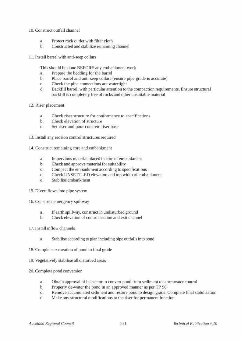
5-31Auckland Regional Council Technical Publication # 10
10. Construct outfall channel
a. Protect rock outlet with filter clothb. Constructed and stabilize remaining channel
11. Install barrel with anti-seep collars
This should be done BEFORE any embankment worka. Prepare the bedding for the barrelb. Place barrel and anti-seep collars (ensure pipe grade is accurate)c. Check the pipe connections are watertightd. Backfill barrel, with particular attention to the compaction requirements. Ensure structural
backfill is completely free of rocks and other unsuitable material
12. Riser placement
a. Check riser structure for conformance to specificationsb. Check elevation of structurec. Set riser and pour concrete riser base
13. Install any erosion control structures required
14. Construct remaining core and embankment
a. Impervious material placed in core of embankmentb. Check and approve material for suitabilityc. Compact the embankment according to specificationsd. Check UNSETTLED elevation and top width of embankmente. Stabilise embankment
15. Divert flows into pipe system
16. Construct emergency spillway
a. If earth spillway, construct in undisturbed groundb. Check elevation of control section and exit channel
17. Install inflow channels
a. Stabilise according to plan including pipe outfalls into pond
18. Complete excavation of pond to final grade
19. Vegetatively stabilise all disturbed areas
20. Complete pond conversion
a. Obtain approval of inspector to convert pond from sediment to stormwater controlb. Properly de-water the pond in an approved manner as per TP 90c. Remove accumulated sediment and restore pond to design grade. Complete final stabilisationd. Make any structural modifications to the riser for permanent function
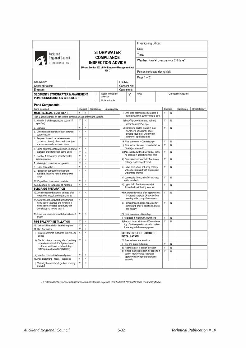
5-32Auckland Regional Council Technical Publication # 10
L:\Lr\stormwater\Revised Templates for Inspection\Construction Inspection Form\Sediment_Stormwater Pond Construction(1).doc
Investigating Officer:
Date:
Time:
Weather: Rainfall over previous 2-3 days?
Person contacted during visit:
STORMWATER COMPLIANCE
INSPECTION ADVICE
(Under Section 332 of the Resource Management Act
1991)
Page 1 of 2
Site Name: File No:
Consent Holder: Consent No:
Engineer: Catchment:
SEDIMENT / STORMWATER MANAGEMENT POND CONSTRUCTION CHECKLIST
:
9
Needs immediate attention
Not Applicable
V Okay ; Clarification Required
Pond Components: Items Inspected Checked Satisfactory Unsatisfactory Checked Satisfactory Unsatisfactory
MATERIALS AND EQUIPMENT Y N
Pipe & appurtenances on-site prior to construction and dimensions checked.
ii) Anti-seep collars properly spaced & having watertight connections to pipe
Y N
1. Material (including protective coating, if specified)
Y N iii) Backfill placed & tamped by hand
under “haunches” of pipe
Y N
2. Diameter Y N
3. Dimensions of riser or pre-cast concrete outlet structure
Y N
iv) Remaining backfill placed in max. 200mm lifts using small power tamping equipment until 600mm cover over pipe is reached
Y N
19. Pipe placement – Concrete pipe Y N
4. Required dimensions between water control structures (orifices, weirs, etc.) are in accordance with approved plans
Y N
i) Pipe set on blocks or concrete slab for pouring of low cradle
Y N
5. Barrel stub for prefabricated pipe structures at proper angle for design barrel slope
Y
Y
N
N
ii) Pipe installed with rubber gasket joints no spalling in gasket interface area
Y N
6. Number & deminsions of prefabricated anti-seep collars
Y
Y
N
N
7. Watertight connectors and gaskets Y N
iii) Excavation for lower half of anti-seep collar(s) reinforcing steel set
Y N
8. Outlet drain valve Y N iv) Entire area where anti-seep collar(s) will come in contact with pipe coated with mastic or other
Y N
9. Appropriate compaction equipment available, including hand & small power tamps
Y N
10. Project benchmark near pond site Y N
vi) Low cradle & bottom half of anti-seep collar installed
Y N
12. Equipment for temporary de-watering Y N
SUBGRADE PREPARATION
vii) Upper half of anti-seep collar(s) formed with reinforcing steel set
Y N
13. Area beneth embankment stripped of all vegetation, topsoil, and organic matter
Y
N
viii) Concrete for collar of an approved mix & vibrated into place (Protected from freezing while curing, if necessary)
Y N
14. Cut-off trench excavated a minimum of 1 metre below subgrade and minimum 1 metre below proposed pipe invert, with side slopes no steeper than 1:1
Y
N
ix) Forms striped & collar inspected for honeycomb prior to backfilling. Parge if necessary
Y N
20. Pipe placement - Backfilling 15. Impervious material used to backfill cut-off trench
Y
N
i) Fill placed in maximum 200mm lifts Y N
PIPE SPILLWAY INSTALLATION Y N
16. Method of installation detailed on plans Y N
17. Bed Preparation Y N
ii) Back fill taken minimum 600mm above top of anti-seep collar elevation before traversing with heavy equipment
Y N
i) Installation trench excavated with 1:1 side slopes
Y N RISER / OUTLET STRUCTURE INSTALLATION
21. Pre-cast concrete structure
i) Dry and stable subgrade Y N
ii) Riser base set to design elevation Y N
ii) Stable, uniform, dry subgrade of relatively impervious material (If subgrade is wet, contractor shall have to defined steps before proceeding with installation)
Y
N
iii) Invert at proper elevation and grade Y N
18. Pipe placement – Metal / Plastic pipe Y N
iii) If more than one section, no spalling in gasket interface area: gasket or approved caulking material placed securely
Y N
i) Watertight connectors & gaskets properly installed
Y
N
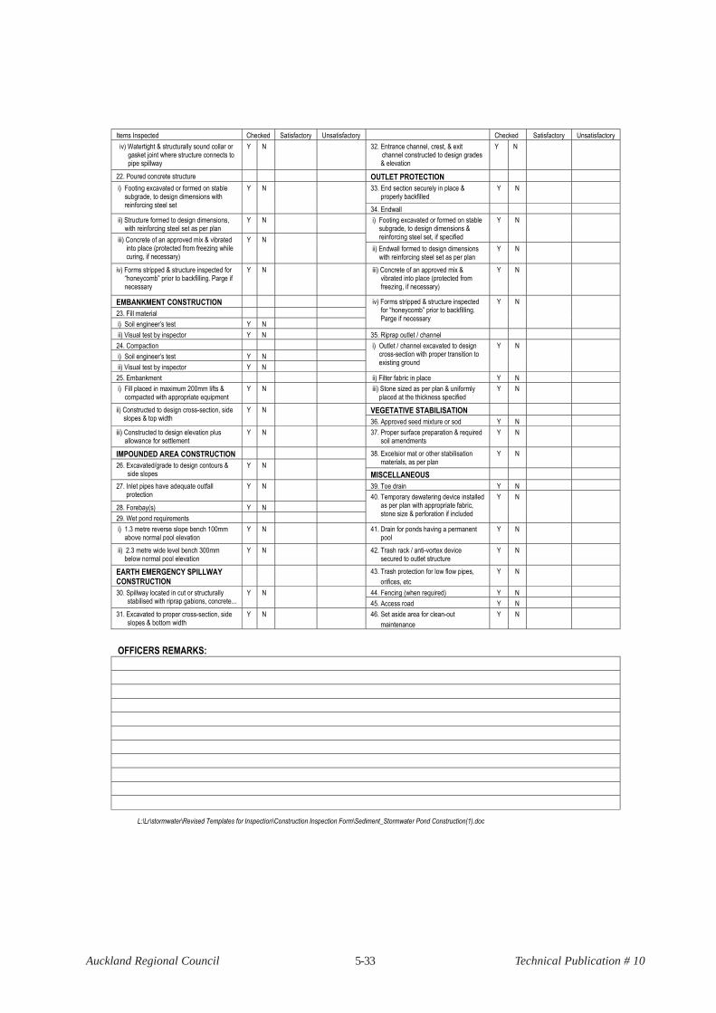
5-33Auckland Regional Council Technical Publication # 10
L:\Lr\stormwater\Revised Templates for Inspection\Construction Inspection Form\Sediment_Stormwater Pond Construction(1).doc
Items Inspected Checked Satisfactory Unsatisfactory Checked Satisfactory Unsatisfactory
iv) Watertight & structurally sound collar or gasket joint where structure connects to pipe spillway
Y N 32. Entrance channel, crest, & exit channel constructed to design grades & elevation
Y N
22. Poured concrete structure OUTLET PROTECTION
33. End section securely in place & properly backfilled
Y N i) Footing excavated or formed on stable subgrade, to design dimensions with reinforcing steel set
Y N
34. Endwall
ii) Structure formed to design dimensions, with reinforcing steel set as per plan
Y N i) Footing excavated or formed on stable subgrade, to design dimensions & reinforcing steel set, if specified
Y N
iii) Concrete of an approved mix & vibrated into place (protected from freezing while curing, if necessary)
Y N
ii) Endwall formed to design dimensions with reinforcing steel set as per plan
Y N
iv) Forms stripped & structure inspected for “honeycomb” prior to backfilling. Parge if necessary
Y N iii) Concrete of an approved mix & vibrated into place (protected from freezing, if necessary)
Y N
EMBANKMENT CONSTRUCTION
23. Fill material
i) Soil engineer’s test Y N
iv) Forms stripped & structure inspected for “honeycomb” prior to backfilling. Parge if necessary
Y N
ii) Visual test by inspector Y N 35. Riprap outlet / channel
24. Compaction
i) Soil engineer’s test Y N
ii) Visual test by inspector Y N
i) Outlet / channel excavated to design cross-section with proper transition to existing ground
Y N
25. Embankment ii) Filter fabric in place Y N
i) Fill placed in maximum 200mm lifts & compacted with appropriate equipment
Y N iii) Stone sized as per plan & uniformly placed at the thickness specified
Y N
VEGETATIVE STABILISATION ii) Constructed to design cross-section, side slopes & top width
Y N
36. Approved seed mixture or sod Y N
iii) Constructed to design elevation plus allowance for settlement
Y N 37. Proper surface preparation & required soil amendments
Y N
IMPOUNDED AREA CONSTRUCTION 38. Excelsior mat or other stabilisation materials, as per plan
Y N
26. Excavated/grade to design contours & side slopes
Y N
MISCELLANEOUS
39. Toe drain Y N 27. Inlet pipes have adequate outfall protection
Y N
28. Forebay(s) Y N
29. Wet pond requirements
40. Temporary dewatering device installed as per plan with appropriate fabric, stone size & perforation if included
Y N
i) 1.3 metre reverse slope bench 100mm above normal pool elevation
Y N 41. Drain for ponds having a permanent pool
Y N
ii) 2.3 metre wide level bench 300mm below normal pool elevation
Y N 42. Trash rack / anti-vortex device secured to outlet structure
Y N
EARTH EMERGENCY SPILLWAY CONSTRUCTION
43. Trash protection for low flow pipes,
orifices, etc
Y N
44. Fencing (when required) Y N 30. Spillway located in cut or structurally stabilised with riprap gabions, concrete...
Y N
45. Access road Y N
31. Excavated to proper cross-section, side slopes & bottom width
Y N 46. Set aside area for clean-out
maintenance
Y N
OFFICERS REMARKS:

5-34Auckland Regional Council Technical Publication # 10
L:\Lr\stormwater\Revised Templates for Inspection\Construction Inspection Form\Sediment_Stormwater Pond Construction(1).doc
ACTION TO BE TAKEN:
No action necessary. Continue routine inspections? Y / N
Correct noted site deficiencies by ____________________________________________________________________________
1st Notice: ___________________________________________________________________________________ 2nd Notice: __________________________________________________________________________________
Submit plan modifications as noted in written comments by ________________________________________________________
Notice to Comply issued ___________________________________________________________________________________
Final inspection, project completed ___________________________________________________________________________
Officers signature: _________________________________
Consent Holder/Engineer/Agent’s signature: __________________________________
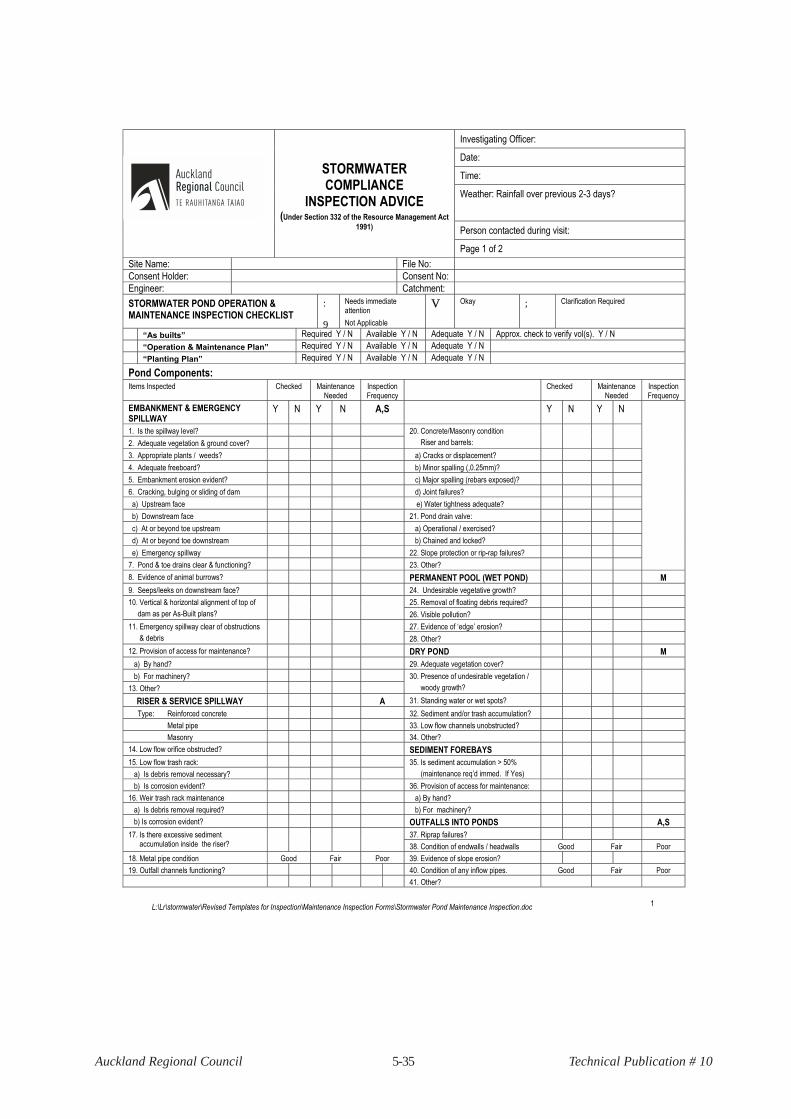
5-35Auckland Regional Council Technical Publication # 10
L:\Lr\stormwater\Revised Templates for Inspection\Maintenance Inspection Forms\Stormwater Pond Maintenance Inspection.doc 1
Investigating Officer:
Date:
Time:
Weather: Rainfall over previous 2-3 days?
Person contacted during visit:
STORMWATER COMPLIANCE
INSPECTION ADVICE
(Under Section 332 of the Resource Management Act
1991)
Page 1 of 2
Site Name: File No:
Consent Holder: Consent No:
Engineer: Catchment:
STORMWATER POND OPERATION & MAINTENANCE INSPECTION CHECKLIST
:
9
Needs immediate attention
Not Applicable
V Okay ; Clarification Required
“As builts” Required Y / N Available Y / N Adequate Y / N Approx. check to verify vol(s). Y / N
“Operation & Maintenance Plan” Required Y / N Available Y / N Adequate Y / N
“Planting Plan” Required Y / N Available Y / N Adequate Y / N
Pond Components: Items Inspected Checked Maintenance
Needed Inspection Frequency
Checked Maintenance Needed
Inspection Frequency
EMBANKMENT & EMERGENCY SPILLWAY
Y N Y N A,S Y N Y N
1. Is the spillway level?
2. Adequate vegetation & ground cover?
20. Concrete/Masonry condition
Riser and barrels:
3. Appropriate plants / weeds? a) Cracks or displacement?
4. Adequate freeboard? b) Minor spalling (,0.25mm)?
5. Embankment erosion evident? c) Major spalling (rebars exposed)?
6. Cracking, bulging or sliding of dam d) Joint failures?
a) Upstream face e) Water tightness adequate?
b) Downstream face 21. Pond drain valve:
c) At or beyond toe upstream a) Operational / exercised?
d) At or beyond toe downstream b) Chained and locked?
e) Emergency spillway 22. Slope protection or rip-rap failures?
7. Pond & toe drains clear & functioning? 23. Other?
8. Evidence of animal burrows? PERMANENT POOL (WET POND) M
9. Seeps/leeks on downstream face? 24. Undesirable vegetative growth?
25. Removal of floating debris required? 10. Vertical & horizontal alignment of top of
dam as per As-Built plans?
26. Visible pollution?
27. Evidence of ‘edge’ erosion? 11. Emergency spillway clear of obstructions
& debris
28. Other?
12. Provision of access for maintenance? DRY POND M
a) By hand? 29. Adequate vegetation cover?
b) For machinery?
13. Other?
30. Presence of undesirable vegetation /
woody growth?
RISER & SERVICE SPILLWAY A 31. Standing water or wet spots?
Type: Reinforced concrete 32. Sediment and/or trash accumulation?
Metal pipe 33. Low flow channels unobstructed?
Masonry 34. Other?
14. Low flow orifice obstructed? SEDIMENT FOREBAYS
15. Low flow trash rack:
a) Is debris removal necessary?
35. Is sediment accumulation > 50%
(maintenance req’d immed. If Yes)
b) Is corrosion evident? 36. Provision of access for maintenance:
16. Weir trash rack maintenance a) By hand?
a) Is debris removal required? b) For machinery?
b) Is corrosion evident? OUTFALLS INTO PONDS A,S
37. Riprap failures? 17. Is there excessive sediment accumulation inside the riser?
38. Condition of endwalls / headwalls Good Fair Poor
18. Metal pipe condition Good Fair Poor 39. Evidence of slope erosion?
19. Outfall channels functioning? 40. Condition of any inflow pipes. Good Fair Poor
41. Other?

5-36Auckland Regional Council Technical Publication # 10
L:\Lr\stormwater\Revised Templates for Inspection\Maintenance Inspection Forms\Stormwater Pond Maintenance Inspection.doc 2
Items Inspected Checked Maintenance Needed
Inspection Frequency
Checked Maintenance Needed
Inspection Frequency
OTHER Y N Y N M CONSTRUCTED WETLAND AREAS Y N Y N A
41. Encroachments on pond or easement
area?
45. Vegetation healthy and growing?
42. Complaints from residents? 46. Evidence of invasive species?
43. Aesthetics 47. Excessive sedimentation in wetland
area?
a) grass mowing required?
b) graffiti removal needed?
c) other (specify)?
44. Any public hazards (specify)?
Inspection Frequency Key A = Annual, M = Monthly, S = After monthly storm
OFFICERS REMARKS:
OVERALL CONDITION OF FACILITY:
In accordance with approved design plans? Y / N In accordance with As Built plans? Y / N
Maintenance required as detailed above? Y / N Compliance with other consent conditions? Y / N
Comments: ___________________________________________________________________________________
Dates by which maintenance must be completed: / /
Dates by which outstanding information as per consent conditions is required by: / /
Officers signature: _________________________________
Consent Holder/Engineer/Agent’s signature: _______________________________