chapter 5 mississippi state universitynsf-pad.bme.uconn.edu/1992/chapter_5.pdfchapter 5: mississippi...
TRANSCRIPT

CHAPTER 5MISSISSIPPI STATE UNIVERSITY
College of EngineeringDepartment of Agricultural and Biological Engineering
Mississippi State, Mississippi 39762-5465
Principal Investigators:
Jerome A. Gilbert (601) 325-3282Jonathan W. Pote (601) 325-3282
53

54 NSF 1992 Engineering Senior Design Projects to Aid the Disabled
Sensory Stimulation Unit for the Severely/ProfoundlyDisabled
Designer: Kalyani VaghelaClient Coordinator: Laura Lea Cobb, PTStarkville Public Schools, Starkville, MS
Supervising Professors: Drs. !.A. Gilbert, S.D. To, J. W. PoteAgricultural and Biological Engineering
Mississippi State, MS 39762-5465
INTRODUCTIONUnder the mandate of federal law P.L. 94-142, thelocal public schools of Starkville, MS offers a classfor the severely and profoundly disabled. The in-structor of this class and the school physical thera-pist expressed a need for a sensory stimulation unitthat could be used to provide visual and auditorystimulation to individual students. An enclosuredevice, shown in Fig. 5.1, was designed to be rolledover the student when lying on his/her side to pro-vide visual and auditory stimulation in an isolatedenvironment. An array of lights on one wall is lit indifferent patterns, and a stereo speaker on the otherwall allows for music and other recorded sounds tobe piped in. “Skylight panels” on the top of the en-
closure can be used to display transparencies and toallow the teacher to observe the students’ reactions.
SUMMARY OF IMPACTStudents who are classified as severely or pro-foundly mentally disabled display a range of mentalabilities from the cognizant communicators withlimited speech patterns to the unresponsive non-communicators with no speech or other developedforms of communication. Although the stimulationunit will be useful for all of these students, it will beparticularly useful for the noncommunicators whomay respond only to the simplest sensory input:light/dark, geometric patterns, and silence/music.By providing this opportunity for a student when
Figure 5.1. Sensory Stimulation Unit. The dark panel on the inside wall contains 35 LED’swhich are lit in patterns.

Chapter 5: Mississippi State University 55
the teachers are working one-on-one with other stu-dents in the class, it is hoped that the sensorystimulation will continue to engage the student andassist in his/her mental development. This devicehas been well received by teachers who view this asan easily accessible form of sensory input that re-quires almost no setup time. It has also been re-ceived well by the parents who view this as a meansof providing their children more time in a stimu-lated environment.
TECHNICAL DESCRIPTIONThe sensory stimulation unit was designed as a rol-lable box-type enclosure that could be rolled over astudent when that student is lying on his/her sideon a side-lying positioner cushion. Aluminumangle was used to construct a frame to which three0.64 cm (l/4 inch) thick plywood panels wereattached. These panels serve as the two sides andthe top as seen in Fig. 5.1. The walls were lined withcarpet. Four locking casters were mounted to theframe so that it could be easily rolled around theroom. The overall size of the structure is 91 cmlong, 91 cm wide, and 61 cm high (36 x 36 x 24 in).
On one of the inside walls of the unit, a 7.9 x 4.7 cm(20 x 12 in) light panel was installed. Thirty-fivelight emitting diodes (LED’s) were arranged in asquare (S), triangle (T), and circle (C) pattern asshown in Fig. 5.2. Each of the three patterns weretotally lit in the following sequence: S+C, S+T, S,T+C,
Figure 5.2. LED Patterns on the LightPanel.
C, T, S+T+C. Each pattern is lit for about 1.3 set sothat the total sequence takes about 9 seconds. Thesequence runs continuously. The timing of thedisplay was controlled by a circuit composed of twooscillators, a counter, NAND gates, and transistordrivers for the LED’s. The circuit was powered by a5v DC power supply. A schematic of the circuit isshown in Fig. 5.3.
Figure 5.3. Circuit to Control LED’s
In addition to the LED light board, two Plexiglaspanels were placed over two 53 x 15 cm (21 x 6 in)openings on the top of the unit to allow for trans-parencies to be viewed. An 8.9 cm (3.5 in) diameterspeaker was mounted on one of the side walls, and aphone jack was connected to it and mounted on theplastic electronics box attached in one corner. Thetotal cost of the project was $148.

56 NSF 1992 Engineering Senior Design Projects to Aid the Disabled
Activator for a Pedal on an Electronic OrganDesigner: Amy Leflore
Client Coordinator: Mike WhiteOffice of Student Support Services, MSU
Supervising Professors: Drs. J.A. Gilbert, 1. W. Pote, D.B. SmithMississippi State University
Agricultural and Biological EngineeringP.O. Box 5465
Mississippi State, MS 39762
INTRODUCTIONA mechanical device was designed to assist a physi-cally disabled woman in playing the organ. Ms. S.Cook suffered from polio as a child and was leftwith limited use of her right leg. It was impossibleto operate both the organ’s floor pedals and the cres-cendo pedal with only her left leg. For this reason,she needed a device that would provide a means ofoperating the crescendo pedal with her knee orhand.
The activator consists of two air cylinders mountedto the organ and connected with tubing. The cylin-ders are connected in such a way that the horizontalmotion of one cylinder mounted under the keyboardwill translate to the vertical motion of the other cyl-inder attached to the pedal (Fig. 5.4).
Cylinder 1
Figure 5.4. Arrangement of AirCylinders.
SUMMARY OF IMPACTThe assist device offers Ms. Cook a much widerrange of musical expression by allowing her to con-trol the volume of the organ at all times without in-
terrupting the flow of music. Since it is a passivemechanical device, it does not require alteration ofthe electronics of the organ and can be easily disen-gaged or removed.
TECHNICAL DESCRIPTIONThe design requirements were: 1) it had to providethe client with a means of operating the pedal withher hand or knee; 2) it could not inhibit another per-son from using the organ; 3) it could not limit herleft foot’s normal range of motion; 4) it must be rela-tively inexpensive.
The activator consists of two double-acting air cyl-inders connected with polyurethane tubing. The aircylinders have a 1 l/16” diameter bore and a 4”stroke length. The tubing has outer and inner di-ameters of 3/8” and l/4”, respectively. The cylin-ders are connected as shown in Fig. 5.4. As the op-erator compresses cylinder 1, air is forced throughthe system causing cylinder 2 to expand, thereforedepressing the pedal. This system also works in thereverse direction.

Cbiapter 5: Mississippi State University 57
Figure 5.5. Organist with Left Hand on Handle attached to Cylinder 1.
Two cylinder mountings were designed to attach thecylinders to the organ (Fig.‘s 5.5 and 5.6). Bothmountings are made of l/4” thick steel and consistof a base plate, a front plate, and two rear sideplates. The base plates are 8 l/2” long. The frontplates have 5/8” diameter holes drilled to allow formovement of the shaft of the cylinders. The tworear side plates are 3/B” in height and act as sup-ports to keep the cylinders from rotating.
A bracket was designed to attach the mounting ofcylinder 2 to an inside panel of the organ (Fig. 5.6).This bracket is made of l/4” steel and has a pin thatpasses through it and the two rear plates of the cyl-inder mounting. This pin allows the cylinder topivot to compensate for the arc movement of thepedal. The bracket is attached to a vertical woodenpanel inside the organ with wood screws. Cylinder2 is attached to the pedal with a hinged clamp. Airrelease valves were placed in the air line to allowothers to play the organ without the device in use.The total cost of the project was approximately $115.
Figure 5.6. Mounting forAir Cylinder 2.

58 NSF 1992 Engineering Senior Design Projects to Aid the Disabled
Automatic Page TurnerDesigner: Susan Johnston
Client Coordinators: Mike White and Donnie PrisockOffice of Student Support Services, MSU
Supervising Professors: Drs. J.A. Gilbert, S.D. To, 1. IV. PoteAgricultural and Biological Engineering
Mississippi State, MS 39762-5465
INTRODUCTIONThe automatic page turner was designed for use byquadriplegics with little or no control of their arms.By activating a puff switch, the user can turn a pageof a book. The page turner would then automati-cally switch off once the page has been turned. Thispage turner uses a vacuum to pick up the page.This approach was decided upon due to the prob-lems experienced by users of page turners that em-ploy padded rollers to turn the page. The paddedrollers occasionally slip or turn two pages instead ofone. That frustrating problem is solved by the useof a vacuum.
SUMMARY OF IMPACTThe page turner was designed to be used with anytype of switch. A puff switch was chosen for theprototype because the client is unable to control his
arms effectively enough to operate other types ofswitches. Only minimal assistance would be neces-sary to the user once the page turner has been set upwith a book in place. The design allows the pages tobe turned in only one direction. However, since nomore than one page would be turned at a time un-like some other page turners, this should not pose aproblem with most books.
TECHNICAL DESCRIPTIONThe page turner can be used with books of a widerange of sizes. The maximum open-book size is 10.5inches high and 17 inches wide. The minimumopen-book size is 5.5 inches high and 11 incheswide. Also, the book can be up to 2 inches thick.The device, as shown in Fig. 5.7, consists of awooden base in which a motor and vacuum pumpare housed and a tilted vertical support surfaceupon which the book is rested.
Figure 5.7. The Page Turner in the Construction Phase.

Chapter 5: Mississippi State University 59
When switched on by a puff from the puff switch, avacuum tube, resting on a pivot, is used to lift thepage. The end of the vacuum tube lowers onto thepage. (Fig. 5.8 schematically depicts the bellows andpump arrangement.) Once the suction cup at theend of the vacuum tube makes contact with thepage, a vacuum is created by the vacuum pump. Atthis time a bellows connecteh to the -
ALUMI’JUM
PLASTIC
Figure 5.8. Side View of PageTurner, Showing Bellows andVacuum Pump.
vacuum tube compresses. This causes the end ofvacuum tube attached to the page to pivot up. Atthe same time, a motor attached to the left sprocketturns on. This causes the track below the base of thebook to move. Attached to this track are page-turning wands. One wand moves under the pageand moves the page to the left, pulling the page
from under the vacuum tube to the other side. Oncethe page has been turned, the wands trigger a limitswitch that turns the page turner off. This stops thewands in a position ready to begin turning anotherpage. Four wands are attached to the track. Twowands opposite each other on the track are used toturn pages. The other two wands (which are placedjust after each of the page-turning wands) are usedto hold the newly turned page in place. Once thepage turner has turned off, the bellows expandsback to its original height. This causes the end ofthe vacuum tube to pivot back down onto the nextpage. Now the page turner is in position to turn thenext page. The electronics controlling the action ofthe device is shown in Fig. 5.9.
To hold the book in the proper position, large bandsconnected to the book base are used. The bookcover is simply slipped under each of the bands.The book base is tilted at a 60 degree angle to alloweasier reading for the customer who is confined tobed. The case and book base are constructed ofplywood. The pivot for the vacuum tube is attachedto an aluminum plate which attaches to the rightside panel of the case. The track arrangement is at-tached to a large aluminum plate (angled at 60 de-grees) which is attached to the base of the case.
The automatic page turner costs four hundred fortydollars ($440) to build. Unfortunately, the prototypewas not completed due to time constraints and vari-ous technical problems.
VAC I------rww I I
Figure 5.9. Schematic of the Control Electronics.
60 NSF 1992 Engineering Senior Design Projects to Aid the Disabled
A Sandwich Holding Device for QuadriplegicsDesigner: Jonathan Lentz
Client Coordinators: Mike White and Donnie PrisockOffice of Student Support Services, MSU
Supervising Professors: Drs. J.A. Gilbert and J. W. PoteAgricultural and Biological Engineering
Mississippi State, MS 39762-5465
INTRODUCTIONA lightweight mechanical device was designed andconstructed to assist a C5 quadriplegic with limitedarm control in the eating of sandwiches. A proto-type was fabricated of 8 mm thick Plexiglas. Thedevice fits over the wrist of the quadriplegic andallows him to clamp a sandwich of variable thick-ness in place and advance it as the front part of thesandwich is eaten. Advancement of the sandwich isaccomplished by lightly bumping the back of theratcheted advancing mechanism to push the sand-wich forward in 14 mm steps.
The design criteria for the sandwich holding devicewere: a. must be able to hold a sandwich and ad-vance it with some input from the disabled person,b. must be lightweight, c. must be washable, d.must not wear out or break in the period of oneyear, and e. must be relatively inexpensive. Basedon the above criteria, a prototype was made out of 8mm thick Plexiglas (Fig. 5.10) so that all of the de-sign criteria were met with the possible exception of“d” that relates to its durability. Although thePlexiglas prototype will not wear out, it could verypossibly be broken if dropped from table height.With this in mind, the final recommendation will beto machine the final device out of a solid block ofnylon.
SUMMARY OF IMPACTAt an initial meeting of biological engineering stu-dents and a group of disabled students, one quad-riplegic expressed a desire to be able to independ-ently eat submarine sandwiches. He had alwaysliked sandwiches because he could balance them onhis lower arm and eat them without much assis-tance. He did, however, have a problem with thesandwich inevitably falling off in the process ofeating it. His desire was to be able to secure thesandwich to his wrist so that he could eat the wholething without it falling and without any assistance
once the sandwich was in place. This project thusbegan with the purpose to solve the sandwich-bal-ancing problem for this one student with the ideathat other individuals with similar disabilities
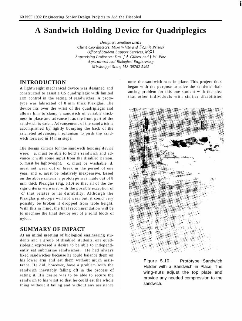
Figure 5.10. Prototype SandwichHolder with a Sandwich in Place. Thewing-nuts adjust the top plate andprovide any needed compression to thesandwich.
Chapter 5: Mississippi State University 61
would also benefit.
It has been estimated that 150,000 persons in theU.S.A. suffer from quadriplegia. A large number ofthese individuals would be able to benefit from afeeding aid like the one developed. In addition tothis population, a large number of cerebral palsyand muscular dystrophy patients could also benefitfrom the device. Thus, there would be considerablepotential demand for this aid.
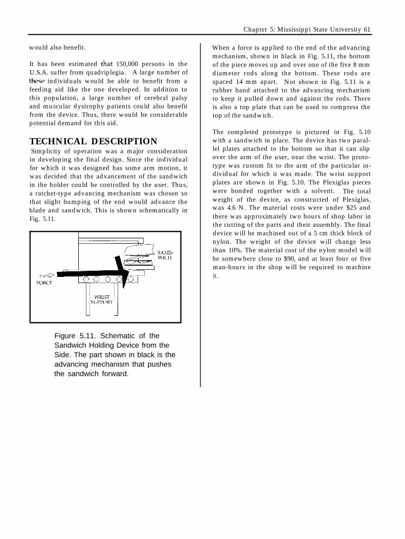
TECHNICAL DESCRIPTIONSimplicity of operation was a major considerationin developing the final design. Since the individualfor which it was designed has some arm motion, itwas decided that the advancement of the sandwichin the holder could be controlled by the user. Thus,a ratchet-type advancing mechanism was chosen sothat slight bumping of the end would advance theblade and sandwich. This is shown schematically inFig. 5.11.
Figure 5.11. Schematic of theSandwich Holding Device from theSide. The part shown in black is theadvancing mechanism that pushesthe sandwich forward.
When a force is applied to the end of the advancingmechanism, shown in black in Fig. 5.11, the bottomof the piece moves up and over one of the five 8 mmdiameter rods along the bottom. These rods arespaced 14 mm apart. Not shown in Fig. 5.11 is arubber band attached to the advancing mechanismto keep it pulled down and against the rods. Thereis also a top plate that can be used to compress thetop of the sandwich.
The completed prototype is pictured in Fig. 5.10with a sandwich in place. The device has two paral-lel plates attached to the bottom so that it can slipover the arm of the user, near the wrist. The proto-type was custom fit to the arm of the particular in-dividual for which it was made. The wrist supportplates are shown in Fig. 5.10. The Plexiglas pieceswere bonded together with a solvent. The totalweight of the device, as constructed of Plexiglas,was 4.6 N. The material costs were under $25 andthere was approximately two hours of shop labor inthe cutting of the parts and their assembly. The finaldevice will be machined out of a 5 cm thick block ofnylon. The weight of the device will change lessthan 10%. The material cost of the nylon model willbe somewhere close to $90, and at least four or fiveman-hours in the shop will be required to machineit.

62 NSF 1992 Engineering Senior Design Projects to Aid the Disabled