chapter 5. cooling production equipment...
TRANSCRIPT

CHAPTER 5.
COOLING PRODUCTION EQUIPMENT AND SYSTEMS
5.1 History of Cooling
5.2 Refrigeration Cycles
5.3 Cooling Production Equipment
5.4 Heat Rejection from Cooling System to the Environment
5.5 Chilled-Water Plant Design
5.6 Ice Storage System
5.7 Sizing Chiller Capacity
The use of ice to refrigerate and thus preserve food goes back to prehistoric times. Through the ages, the seasonal harvesting of snow and ice was a regular practice of most of the ancient cultures: Chinese, Hebrews, Greeks, Romans, Persians.
Ice and snow were stored in caves or dugouts lined with straw or other insulating materials. The Persians stored ice in pits called yakhchals. Rationing of the ice allowed the preservation of foods over the warm periods.
This practice worked well down through the centuries, with icehouses remaining in use into the twentieth century.
5.1 History of Cooling
5.1.1 Ice Harvesting

An ancient ice house, called a yakhchal, built in Kerman, Iran during the Middle Ages, for storing ice during summers.
A domed icehouse (ghiacciaia) half-sunk into a shaded slope, Boboli Gardens, Florence, Italy
Today’s ice coolers
5.1.2 Chemical Cooling
In the 16th century, the discovery of chemical refrigeration was one of the first steps toward artificial means of refrigeration.
Sodium nitrate (NaNO3)or potassium nitrate(KNO3), when added to water, lowered the water temperature and created a sort of refrigeration bath for cooling substances. In Italy, such a solution was used to chill wine and cakes.

The first known method of artificial refrigeration was demonstrated by William Cullen at the University of Glasgow in Scotland in 1756. Cullen used a pump to create a partial vacuum over a container of diethyl ether, which then boiled, absorbing heat from the surrounding air. The experiment even created a small amount of ice, but had no practical application at that time.
In 1758, Benjamin Franklin and John Hadley, professor of chemistry at Cambridge University, conducted an experiment to explore the principle of evaporation as a means to rapidly cool an object. Franklin and Hadley confirmed that evaporation of highly volatile liquids such as alcohol and ether, could be used to drive down the temperature of an object past the freezing point of water. They conducted their experiment with the bulb of a mercury thermometer as their object and with a bellows used to "quicken" the evaporation; they lowered the temperature of the thermometer bulb down to −14 °C while the ambient temperature was 18 °C
5.1.3 First Refrigeration Systems
bellows
In 1805, American inventor Oliver Evans designed but never built a refrigeration system based on the vapor-compression refrigeration cycle rather than chemical solutions or volatile liquids such as ethyl ether.
In 1820, the British scientist Michael Faraday liquefied ammonia and other gases by using high pressures and low temperatures.
In 1834, Jacob Perkins, an American living in Great Britain, obtained the first patent for a vapor-compression refrigeration system. Perkins built a prototype system and it actually worked, although it did not succeed commercially.
In 1842, an American physician, John Gorrie, designed the first system for refrigerating water to produce ice. He also conceived the idea of using his refrigeration system to cool the air for comfort in homes and hospitals (i.e., air-conditioning). His system compressed air, then partially cooled the hot compressed air with water before allowing it to expand while doing part of the work required to drive the air compressor. That isentropic expansion cooled the air to a temperature low enough to freeze water and produce ice
In 1848, Alexander Twining began experimenting with vapor-compression refrigeration and obtained patents in 1850 and 1853. He is credited with having initiated commercial refrigeration in the United States by 1856.
In 1859, in France, Ferdinand Carré developed the first gas absorption refrigeration system using gaseous ammonia dissolved in water (referred to as "aqua ammonia") and the system was patented in 1860. Due to the toxicity of ammonia, such systems were not developed for use in homes, but were used to manufacture ice for sale.

5.2 Refrigeration Cycles
Natural modes of heat transfer, conduction, convection and radiation move heat from high-
temperature sources to low-temperature destinations. This is called the second law of
thermodynamics.
Cold is the absence of heat, hence in order to decrease a temperature, one "removes heat "
rather than "adding cold."
Refrigeration moves heat from low-temperature sources to high-temperature destinations.
In order to satisfy the second law of thermodynamics (i.e., natural flow of heat), some form
of work must be performed to accomplish this. The work is traditionally done by
mechanical work which requires energy.
5.2.1 Vapor Compression Cycle
This process involves boiling and condensing fluids called refrigerants at temperatures that will
produce a cooling effect.
Compressor draws refrigerant from the evaporator and compresses it into high temperature and
high pressure gas.
Condenser returns the refrigerant gas to its liquid state.
Expansion valve reduces the pressure of liquid refrigerant thereby cooling it before it enters the
evaporator.
Evaporator evaporates the liquid refrigerant by absorbing the heat of the warm air.
Vapor compression cycle
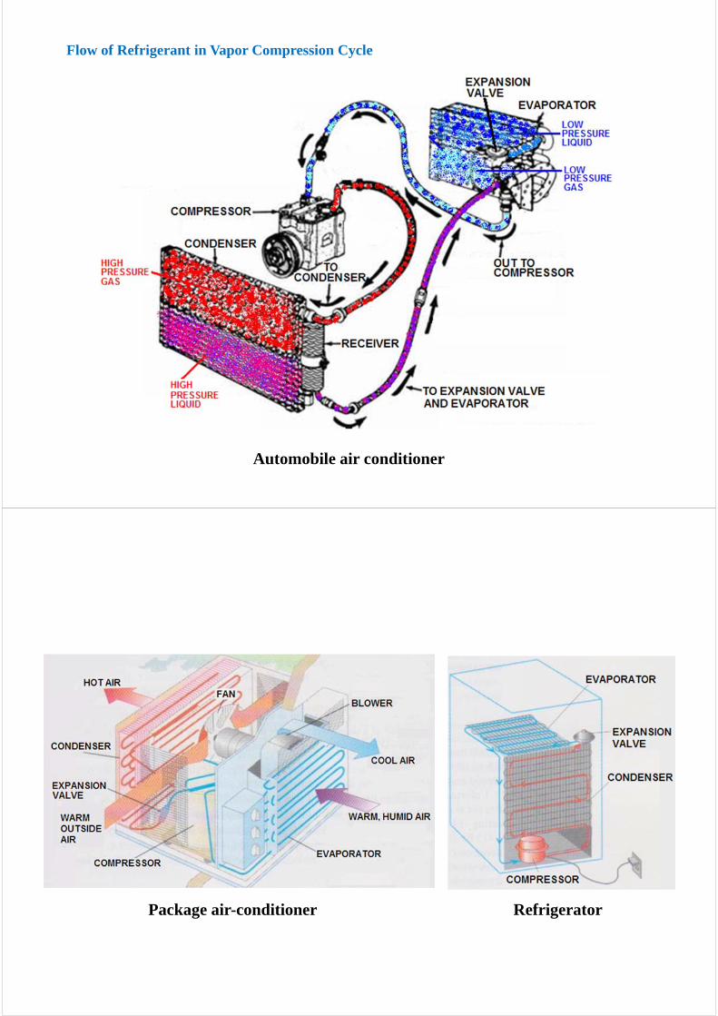
Flow of Refrigerant in Vapor Compression Cycle
Automobile air conditioner
Package air-conditioner Refrigerator

Expansion Valve (Thermal Expansion Valve, TXV)
CFC: Chlorofluorocarbons (R-11, R-12)Very efficient.Very stable, which translates into long-lasting harm (ozone depletion).No longer produced in developed countries, regulated by the Montreal Protocol of 1987.
HCFC: Hydrochlorofluorocarbons (R-22)Less stable, and their harmful effects are not as long-lasting.Scheduled for phase-out in 2020 due to its ozone depletion potential.
HFC: Hydrofluorocarbons (R-134A)Not regulated by the Montreal Protocol.Developed for its low ozone depletion potential.Significant warming potential.
AmmoniaHistorically preferred refrigerant for industrial applications, such as breweries and dairies.The thermal performance is excellent and inexpensive.Extremely toxic and is classified by code as a flammable refrigerant.Potentially ammonia could be used in large central cooling plants to produce chilled water for
buildings.
Air, CO2
Refrigerants for Vapor Compression Cycle

5.2.2 Absorption Refrigeration Cycle
The absorption refrigeration cycle uses water as a refrigerant.
At 5-7 mmHg vacuum, water boils at about 4-5°C and can be used as a refrigerant to produce
chilled water or air.
When water boils in an evaporator, as in the vapor compression cycle, it absorbs heat from the fluid
being cooled. (EVAPORATOR)
The water vapor produced in the evaporator is moved to a chamber that contains a strong solution
of hygroscopic chemical such as lithium bromide. (ABSORBER)
As the solution becomes more dilute, it must be regenerated by removing water. The water
contained in the LiBr solution is removed by heating the dilute solution. The source of the heat can
be steam, hot water, or direct firing with gas or oil. (GENERATOR)
The water vapor removed from the dilute LiBr solution is condensed into liquid by cooling water
from cooling tower. (CONDENSER)
Absorption chillers use less electric energy than the vapor compression chillers do.
Absorption chillers are less noisy because there are no compressors.

COP : the ratio of the cooling effect divided by the power used to accomplish the process.
– The COP of the absorption cycle: 0.5~1.0
– The COP of the vapor compression: 2.5~7
Most of the energy used in the absorption process: heat
Most of the energy used in the vapor compression cycle: electricity
– Electricity is a more expensive energy form than heat by burning fuels, but its COP is much higher
5.2.3 Coefficient of performance (COP) of Refrigeration Cycles
Economical alternative or supplement to vapor compression or absorption refrigeration.
Common in hot-arid regions.
1. Direct method
2. Indirect method
5.2.4 Evaporative Cooling

5.2.5 Desiccant cooling
The wheel rotates slowly, typically at about 20 rpm.
Gas is used as a fuel for cooling system (Absorption chiller).
Desiccant wheel is used for dehumidification.
– Absorbs humidity from outside air in the first air stream.
– Desiccant wheel is dried out by a heater.
Cooling coil is used to reduce temperature.

5.3 Cooling Production Equipment
The selection of a cooling production system depends on:
size of the project budgetconcerns about costs over the life cycle operating costs including utilities and maintenance
Two basic options:
Direct expansion systems: Package air-conditionerChilled water systems: Vapor compression chillers, Absorption chillers
5.3.1 Direct Expansion (DX) System
Refrigerant is directly used in the coil.
DX system with reciprocating or scroll compressors are common.
Mostly for small tonnage or
Very economical at first, but the power demand is high due to high condensing temperatures.
Basic DX system components

Alternative DX system configurations (fans not shown)
5.3.2 Chilled-Water Systems
Water is low-cost thermal transfer medium.
Basic chilled water system
Chiller

The advantages of chilled-water system
Initial costs are generally expensive but have advantages that may be important for individual projects:
Quieter and less visible
Less subject to leaks
More flexible
Easier to maintain
Chilled Water versus DX
Monitoring and maintaining a chiller plant
5.3.2.1 Vapor Compression Chillers
Chillers operating on the vapor compression cycle are classified according to the type
of compressor they use, including:
1) Reciprocating Chillers
2) Scroll Chillers
3) Rotary Helical Chillers
4) Centrifugal Chillers

1) Reciprocating Chillers
Reciprocating chillers use positive displacement compression, which may contain two or more cylinders.
Due to reciprocating motion, this type of compressor is generally noisier and uses more power than rotary-type compressors.
Capacity control is achieved by cycling compressors or deactivating cylinders in steps. Cycling and step control will result in varying temperature of the supply water.
Reciprocating chillers are not appropriate if precise temperature control is required.
50 to 60 tons 15 to 40 tons
Reciprocating compressor
Reciprocating compressor
Operation of Reciprocating Compressor

Scroll compressors
2) Scroll Chillers
Scroll chillers use positive displacement scroll compressors.
The scroll compressor uses one fixed and one orbiting scroll to compress refrigerant gas vapors from the evaporator to the condenser of the refrigerant path.
Scroll compressors are a relatively recent compressor development and will eventually replace reciprocating compressors in many cooling system applications, where they often achieve higher efficiency and better part-load performance and operating characteristics.
Scroll chillers are available only in small capacities, and generally use multiple compressors.
Capacity control is achieved by staging of compressors
Operation of Scroll Compressor
Fixed scroll
Orbiting scroll
The upper scroll is stationary and contains the refrigerant gas discharge port. The lower scroll is driven by an electric motor shaft assembly imparting an eccentric or orbiting motion to the driven scroll. That is, the rotation of the motor shaft causes the scroll to orbit - not rotate -about the shaft center.
This orbiting motion gathers refrigerant vapors at the perimeter, pockets the refrigerant gas, and compresses it as the orbiting proceeds.
The trapped pocket works progressively toward the center of the stationary scroll and leaves through the discharge port.

3) Helical Rotary Chillers (Rotary Screw Chillers)
Helical rotary chillers use single-screw or twin-screw compressors.
The screw compressor is a positive displacement helical-axial design and is well suited to high-pressure refrigerants.
Rotary screw chillers provide significant operational energy savings because they can match full load or part load as small as 10 percent of the chiller's capacity.
The operation of rotary screw chillers is relatively vibration-free.
Capacity control is achieved by a slide valve.
Screw compressors
The single-screw compressor consists of a single cylindrical main rotor that works with a pair of gate rotors.
Both the main rotor and the gate rotors can vary widely in terms of form and mutual geometry.
The main rotor has six helical grooves, with a cylindrical periphery and globoid root profile. The two identical gate rotors each have 11 teeth and are located on opposite sides of the main rotor.
The compressor is driven through the main rotor shaft, and the gate rotors follow by direct meshing action at 6:11 ratio of the main rotor speed.
The operation of the single-screw compressor can be divided into three distinct phases: suction, compression, and discharge.
Operation of Single-Screw Compressor

In the twin-screw compressor, compression is achieved by two intermeshing rotors housed in a close fitting casing .
The male rotor has lobes which are non-symmetrical profile sections formed vertically along the rotor length and these mesh with corresponding recesses on the female rotor.
As the rotors turn, gas is drawn through the inlet port to fill the space between adjacent lobes. When the interlobe space along the rotor length is filled the rotation of the rotors moves the end of the lobes past the inlet port so sealing the interlobe space
Operation of Twin-Screw Compressor
As the rotors continue to rotate, the intermeshing of the lobes on the discharge side of the compressors progressively reduces the space occupied by the gas causing compression.
Compression continues until the interlobe space becomes exposed to the outlet port in the casing and the gas is discharged.
The machine has few moving parts (seven): slide valve, two rotors and two sets of heavy-duty industrial bearings. This construction allows the compressor to operate at two-pole motor speeds (3600rpm synchronous) with high efficiency.
Slide Valve Unloading Mechanism in Rotary-Screw Compressors
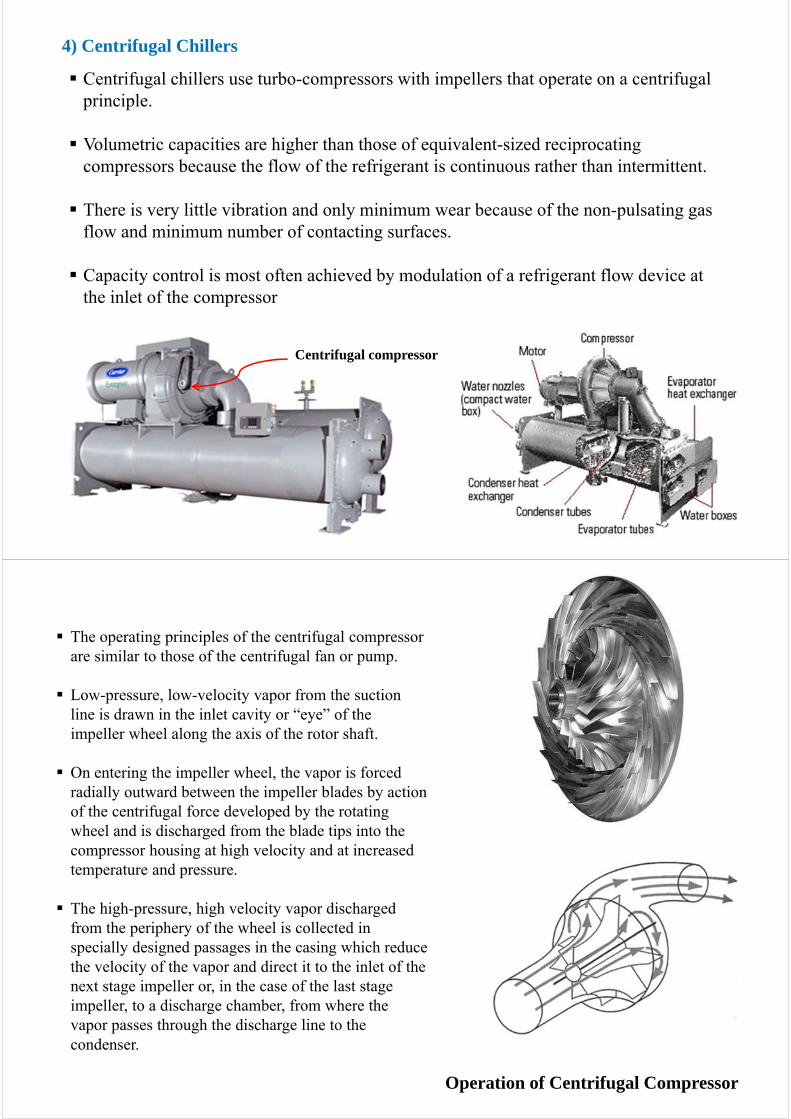
4) Centrifugal Chillers
Centrifugal chillers use turbo-compressors with impellers that operate on a centrifugal principle.
Volumetric capacities are higher than those of equivalent-sized reciprocating compressors because the flow of the refrigerant is continuous rather than intermittent.
There is very little vibration and only minimum wear because of the non-pulsating gas flow and minimum number of contacting surfaces.
Capacity control is most often achieved by modulation of a refrigerant flow device at the inlet of the compressor
Centrifugal compressor
The operating principles of the centrifugal compressor are similar to those of the centrifugal fan or pump.
Low-pressure, low-velocity vapor from the suction line is drawn in the inlet cavity or “eye” of the impeller wheel along the axis of the rotor shaft.
On entering the impeller wheel, the vapor is forced radially outward between the impeller blades by action of the centrifugal force developed by the rotating wheel and is discharged from the blade tips into the compressor housing at high velocity and at increased temperature and pressure.
The high-pressure, high velocity vapor discharged from the periphery of the wheel is collected in specially designed passages in the casing which reduce the velocity of the vapor and direct it to the inlet of the next stage impeller or, in the case of the last stage impeller, to a discharge chamber, from where the vapor passes through the discharge line to the condenser.
Operation of Centrifugal Compressor

Open versus Hermetic
Open chillers: Externally coupled to the compressorHermetic chiller: Housed with the compressor in enclosure and cooled by the
surrounding refrigerant
Direct versus Gear Drive
Direct-drive: operating at 3600 RPMGear-drive : operating at speeds from 6000 to 20,000 RPM
Low Pressure Refrigerants
More efficient than high-pressure refrigerants.Require physically larger equipment for the same capacity.
5.3.2.2 Design Variations

Indirect-fired chillers :
Steam of 5-to 150-psi or hot water of 15 to 400F is used for the generator.
Available up to 2000 tons of cooling capacity
Direct-fired chillers:
Natural gas combustion or hot-process waste gas is used for the generator.
Available up to 1500 tons of cooling capacity
Single-Stage Absorption
One generator
Two-Stage Absorption
Two generators (high-temperature and low-temperature generators)
5.3.2.3 Absorption Chillers

Operation of a Single-Stage Indirect Absorption Chiller
(One generator)
Operation of a Two-Stage Indirect Absorption Chiller
(Two generators)

5.3.2.4 Engine Driven Chillers
5.4 Heat Rejection from Cooling System to the Environment
Air conditioning systems use refrigeration processes to move heat from the indoor to the outdoor environment. The refrigeration cycle absorbs heat by the evaporation of liquid refrigerant in the evaporator (indoor coil), and rejects heat by the condensation of vapor refrigerant in the condenser (outdoor coil).
The heat rejected from a refrigeration system is the sum of the actual cooling load and the energy added by the refrigeration equipment (compressor and circulation pumps).
The condenser may use either water (produced by a cooling tower) or ambient air as the heat rejection medium.
Since cooling tower water is normally cooler than air during the summer, water-cooled condensers are generally more energy-efficient.

Air-cooled condensers use air to cool and condense refrigerant gas to the liquid state.
These systems normally require 17-25 m3/min of air per ton of refrigeration.
Condensing temperatures range from 46 to 60°C, depending on climatic conditions. In general, higher condensing temperature will increase the power requirement (fan power) and decrease the cooling system’s performance.
Advantages over water-cooled system:
No problem of water freezingNo water treatment requiredNo condensing water pump requiredLower initial cost
5.4.1 Air-Cooled System
FansCondenser

Sources of condensing water include spray ponds, domestic supply water, wells, surface water, and cooling towers.
Water from these sources is lower in temperature than air is during the summer. Lower condensing temperatures allow higher refrigeration efficiency, and water is generally preferred to air on this basis.
Using domestic water in condensers is wasteful and expensive; only used for small systems as a convenience when other options are not practical.
Spray ponds are used in stead of cooling towers when the site conditions are favorable. However, spray ponds are more costly than cooling towers and require large surface areas.
Wells and river water are practical source of cooling water when they are readily available. However, it is necessary to provide more elaborate water treatment and filtration facilities than with conventional heat rejection methods.
5.4.2 Water-cooled system
Spray cooling pond atWLW radio station,Cincinnati, Ohio, U.S.A.
Spray cooling pond at Kozloduy Nuclear Power Plant,Kozloduy, Bulgaria

5.4.3 Cooling Towers
Used in most applications, cooling towers produce water at an appropriate temperature for condensing by evaporation.
Approximately 7 percent of the circulation water is evaporated and new water is supplied to make up for the lost water.
Evaporation is achieved by flowing the water over a fill material in the tower, which is designed to ensure good contact between water and air.
Selection of the right cooling tower depends on many factors:- available space,- access for installation, - possible replacement of the tower, - the initial budget,- expected cost over the life cycle (energy, maintenance, and replacement cost).
Air Flow in Cooling Towers
Three basic operating concepts for moving air through a cooling tower:
- Gravity draft- Induced draft- Forced draft
Air flow may be horizontal (crossflow) or vertical (counterflow) through the fill.
Cooling towers for power plants create a chimney effect (gravity draft) to make the air flow past the water.
These towers are bulky and tall and thus are not used in building air-conditioning

Structure of a induced draft, counterflow cooling tower

Placement of Cooling Towers
Free circulation of air is needed for efficient operation of the cooling tower.
Discharge from the cooling tower should be unimpeded, and any obstructions at the inlet should be held at a distance.
A general rule for induced-draft towers is to allow a clear air passage equal to the tower intake height.
A general rule for forced-draft towers is to allow air passage space equal to 1.5 times the tower width.
Violation of these guidelines can cause recirculation of humid discharge air into the inlet or impede the fresh airflow, which in turn causing degraded performance.
Discharge air from cooling towers is humid and can contain droplets of water treatment chemicals. Surfaces exposed to the discharge air may become corroded, soiled, or discolored.
Wind can blow humid air and water droplets horizontally from the tower discharge or through the tower body.
Cooling towers generate very high level of noise from the fan. When the cooling towers are to be installed on the ground level, proper noise barriers should be designed.

Large custom-designed masonry cooling towers may be constructed of brick, stone, metal, or other materials to match the building material and can also be constructed as a part of the building.
Central cooling tower at Clayton State University,Morrow, GA, U.S.A.
5.5 Chilled-Water Plant Design
5.5.1 Basic Configurations
Central plant
Distributed water chillers
Single- and double-pipe chilled water loops
District plant

Central Plant
Compared with multiple plants, a central plant offer the advantage of requiring less space and fewer auxiliary systems.
The greatest advantage is the size of equipment that can take advantage of the diversified load, which may be as low as 50 percent of the loads of individual buildings or areas of buildings.
Central plants also offer operating flexibility, inexpensive redundancy, and centralized maintenance.
The central plant is generally the least expensive and best overall solution for a large single building or closely coupled building complex.
When growth of the cooling load is unknown or the load is physically separated, distributed plants are appropriate to serve separate areas.
Plants can be added as needed, with little commitment of initial investment in space or other provisions for the future.
Distributed chillers will require smaller piping than central plant will, but the sum of multiple plant capacities is usually substantially greater than the capacity of a central plant.
Another application of distributed chiller plant is in high-rise buildings of over 50 stories, when two or more vertical zones are necessary to limit static pressure in chilled-water piping system.
Distributed Water Chillers

Single-pipe loops have a distribution pipe, generally installed underground, that passes by each building served by the system. Some buildings will have water chillers, and some will not.
The water chillers serve to reduce the temperature of the water in the loop. Chilled water used by the buildings is returned to the loop at a higher temperature.
Ideally, the chillers and loads need to be evenly distributed so that adequate chilled is available at all buildings.
Single-Pipe Chilled Water Loop
Water Chiller AHU
Double-Pipe Chilled Water Loops
Double-pipe chilled-water loops use separate supply and return piping so that the same water temperature is available to all buildings.
Because of the extra piping, this loop will generally be more expensive to install.
But, its performance is superior to that of the single-pipe loop.
District Plants
A large central chilled water plant may serve a campus, district, or community.
Such plants rely on economies of scale (i.e., massive scale) to provide low cost per unit of capacity. These savings are used to offset the expense of distribution piping.
The district plant centralizes maintenance, keeps noise and cooling tower moisture away from other buildings.
If chilled-water generation is combined with power or heat generation, a district plant is ideal for incorporating cogeneration, which uses the waste heat from electric power generation for heating or cooling.
The buildings served by a district plant can save space for chillers and boilers, by receiving energy with heat exchangers.
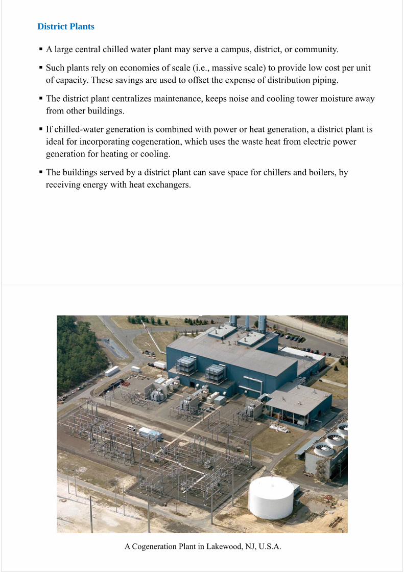
A Cogeneration Plant in Lakewood, NJ, U.S.A.

5.5.2 Combination and Fossil-Fuel Alternatives
Vapor compression and absorption or engine-driven chillers can be used in combination to control energy cost in chilled-water plants.
Typically, vapor compression chillers are operated to cover the base load, and absorption or engine-driven chillers are used to meet peak loads, reducing demand charges for electricity.
Standby power generators are desirable for many critical building types, such as data centers and healthcare facilities.
Gas turbine standby power generator

5.5.3 Chiller Circuiting Arrangements
Multiple water chillers can be circuited in series, in parallel, or in a combined series/parallel arrangement.
Series Arrangement
A series arrangement reduces water temperature successively through two chillers. The discharge chiller will produce low-temperature leaving water, and the inlet chiller will produce water at a temperature between the return and supply conditions.
Advantage:
Only the second chiller is in charge of producing low-temperature discharge water.
Disadvantage:
All the chilled water is pumped through both chillers, resulting in high pumping energy.
The series arrangement can be very economical in its initial cost, since piping is simple and only one pump is required. However, a standby pump and bypass piping are recommended to ensure continuity of operation.

Parallel Arrangement
The use of single pump for multiple chillers in parallel will allow mixing of return water with supply water, unless all the chillers are being operated. Under this condition, supply water temperature may be too high for good humidity control by the air-conditioning system.
Using one pump per chiller is preferred.
Advantage: flexibility and reliability
- Under a partial load condition, chillers and their pumps can be shut down.- Some machines can be withdrawn from service for maintenance without affecting
the operation of others.
Disadvantage: Each chiller will be required to produce the same leaving water temperature. Therefore, slightly higher compressor power is required.
Combination Series/Parallel Arrangement
Absorption chiller
Vapor compression chillers
A combination of series/parallel arrangement may be appropriate for certain applications.
If absorption and vapor compression chillers are used in the same plant, absorption chillers are placed ahead of the vapor compression machines.
This design is more economical, because absorption chillers are used to produce higher temperature leaving water and vapor compression chillers are used to produce low temperature water.

5.5.4 Distribution Pumping Arrangements
Unit loop for a small building. Unit and primary loops for large single building. Unit, primary, and secondary loop for groups of buildings.
5.6 Ice Storage System
Ice is generated by low-temperature brine or direct refrigeration cycle, using low-cost nighttime electric energy, and stored in either open vats or enclosed housings.
Chilled water is circulated through the ice or closed storage modules during daytimes, causing the ice to melt and release its latent cooling effect.
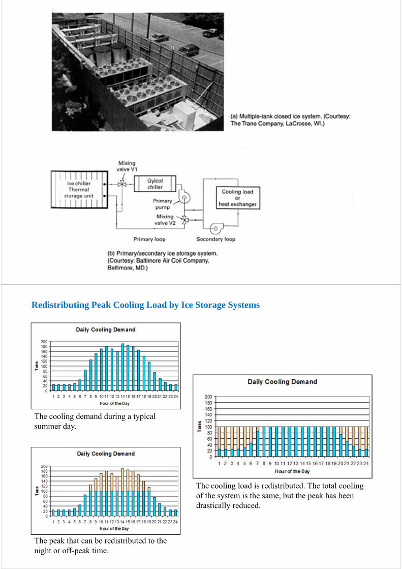
The peak that can be redistributed to the night or off-peak time.
The cooling demand during a typical summer day.
Redistributing Peak Cooling Load by Ice Storage Systems
The cooling load is redistributed. The total cooling of the system is the same, but the peak has been drastically reduced.

5.7 Sizing Chiller Capacity
5.7.1 Tons of Refrigeration
Tons:
Long ton (used in UK) = 2240 lb (=1016 kg)Short ton (used in US) = 2000 lb (=907 kg)Metric ton (tonne) = 1000 kg
Conversion factors between energy units:
1 kg = 2.2046 lb1 lb = 0.4536 kg1 cal = 4.186 J1 Btu = 1055 J = 252 cal = 0.252 kcal1 kcal = 3.968 Btu
Heat of fusion of water(ice):
333.55 kJ/kg = 79.68 kcal/kg = ( ) = 143.714 Btu/lb = 144 Btu/lblb/kg2.2
Btu/kcal968.3kcal68.79
1 RT (1 Refrigeration Ton):
The rate of heat removal required to freeze a metric ton (1000 kg) of water at 0℃in 24 hours.
1RT = = 3320 kcal/h
1 USRT (1 US Refrigeration Ton):
The rate of heat removal required to freeze a short ton (2000lb) of water at 32 ºF in 24 hours.
1USRT = = 12000 Btu/h = 3024 kcal/hh24
lb2000Btu/lb 441
h24
kg1000g9.68kcal/k7

Step 1: Calculate cooling loads for sensible heat and latent heat gains. Assume that the cooling loads are calculated to maintain design indoor temperature and relative humidity at ta and RHa, respectively.
Step 2: Calculate sensible heat factor (SHF)
Step 3: Draw a SHF line on the psychrometric chart starting from the benchmark point.
Step 4: Draw a parallel line passing through the state point of ta and RHa which is parallel to the SHF line.
Step 5: Determine cooling coil dew-point temperature (apparatus dew-point temperature, ADP).
Step 6: Determine supply air (SA) temperature (tc) at the cooling coil by considering bypass factor.
Step 7: Determine supply air mass (or volume) and chiller capacity (RT or USRT) by considering heat gains from ductwork and pipe distribution systems. This is done in somewhat subjective manner by multiplying a safety factor (10 to 15%)
Load Cooling Total
Load Cooling SensibleSHF
5.7.2 Calculating Chiller Capacity (RT or USRT)
SHF line on Psychrometric Chart
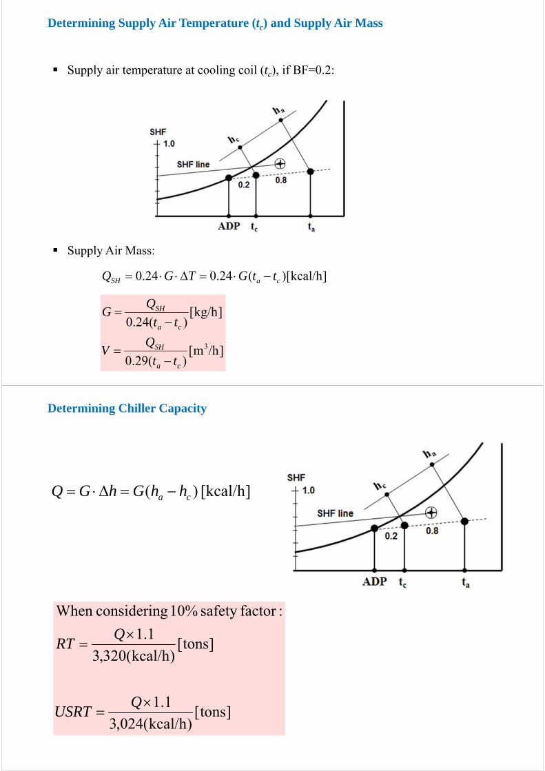
Supply air temperature at cooling coil (tc), if BF=0.2:
Supply Air Mass:
]kcal/h)[(24.024.0 caSH ttGTGQ
]/hm[)(29.0
]kg/h[)(24.0
3
ca
SH
ca
SH
tt
QV
tt
QG
Determining Supply Air Temperature (tc) and Supply Air Mass
][kcal/h)( ca hhGhGQ
]tons[)kcal/h(024,3
1.1
]tons[)kcal/h(320,3
1.1
:factorsafety 10% gconsiderinWhen
QUSRT
QRT
Determining Chiller Capacity

Example 1: Determine the state of supply air with the given conditions.
75.0000,20000,60
000,60
SHF
① DB=26℃, RH=55%
② SHF=0.75
③ t=ta-(ta-tc)=16℃
④
⑤ SA
QSH = 60,000 kcal/hQLH = 20,000 kcal/hta = 26℃RHa = 55%ta – tc =10℃BF = 0
Example 2: Determine the ADP and the mass of supply air with the given conditions.
① DB=22℃, RH=55%
② SHF=0.75
③ tc=ta-10=12℃
③
④
From the chart: ADP=10.3℃
)(24.0 ca
SH
tt
qG
[kg/h] 25,000)10(24.0
000,60
75.0000,20000,60
000,60
SHF
QSH = 60,000 kcal/hQLH = 20,000 kcal/hta = 22℃RHa = 55%ta – tc =10℃BF = 0

Example 3: Determine the mass of supply air and the chiller capacity.
1) Mass of supply air:
with 10% safety factor
2) Chiller capacity with 5% safety factor:
h]37,500[kg/C]10[C]kg0.24[kcal/
l/h]90,000[kca
)(24.0 oo
ca
SH
tt
QG
tons5049.73,320
1.0540,000)(117,000
/h]3,320[kcal
1.05)(
OAtotal QQ
RT
]kg/h[250,411.1500,37 G
QSH = 90,000 kcal/hQLH = 27,000 kcal/hta – tc =10℃Qoa= 40,000 kcal/h (outdoor air ventilation load)
h]13,636[kg/1124.0
000,36
G
][kg/h 9,091545,4636,13
[kg/h] 4,54531636,13
RA
OA
G
G
8.0000,9000,36
000,36
SHF
Example 4: Determine the mass of supply air and the chiller capacity in USRT.
Indoor design conditions: ta = 27℃ RHa = 50%Outdoor design conditions: to= 32℃ RHo = 68%QSH = 36,000 kcal/hQLH = 9,000 kcal/hta – tc =11℃Goa= 1/3 of supply air mass (Goa : the mass of outdoor air)

State of the mixed air(MA):
[kcal/kg] 15.70636,13
545,44.20091,935.13
MA
OAOARARAMA
MAMAOAOARARA
G
GhGhh
GhGhGh
①DB=27℃, RH=50%
③
②DB=32℃, RH=68%
③DB=16℃
⑥MA
⑦
[kcal/h] 77,043)05.107.15(636,13)( hGQ SAMA
Chiller capacity with 10% safety factor: tons0.28024,3
1.1043,77
USRT