chapter 4: straight line drawing ronald kieft. contents introduction algorithm 1: shift method...
Post on 21-Dec-2015
237 views
TRANSCRIPT

Chapter 4: Straight Line Drawing
Ronald Kieft

Contents
Introduction Algorithm 1: Shift Method Algorithm 2: Realizer Method Other parts of chapter 4 Questions?

Introduction
Straight Line Drawing deals with plane graphs Plane graph: can be drawn without edge
crossings, given a fixed embedding However, the edges can be curved
It was proved that every plane graph G has a straight line drawing Which can be found in polynomial time But the area of the drawing was not bounded
• Impractical

Introduction cont’d
In 1990 two methods were found which did have a bound on the area Fraysseix: area is a grid of (2n - 4) x (n – 2) Scnhyder: area is a grid of (n – 2) x (n – 2)
Both method have O(n) implementations Question: what is the minimum size of a
grid required for a Straight Line Drawing? Probably ceil(2n / 3) x ceil(2n / 3) Has not yet been proven

Algorithm 1: Shift Method
The method by Fraysseix is called the “Shift Method” Finds a Straight Line Drawing for every
plane graph G with n ≥ 3 Area is bouned by a grid of size (2n – 4) x (n
– 2) Shift Method can be divided into two steps:
Step 1: Construct a Canonical Ordering Step 2: Insert vertices one by one, according
to the Canonical Ordering (and make sure the graph stays a Straight Line Drawing)

Algorithm 1: Shift Method
Step 1: Construct a Canonical Ordering What is a Canonical Ordering?
• Cycle: path through G which starts and ends at the same vertex
• Chord: an edge between two non-consecutive vertices on a Cycle
• Outer Cycle; Co(G): the boundary of the outer face
• π(v1, v2,…, vn): ordering of all vertices of G
• Gk: a subgraph of G formed by the first k vertices of ordering π

Algorithm 1: Shift Method
Examples of all definitions:

Algorithm 1: Shift Method
The ordering π is a Canonical Ordering if for every k, 3 ≤ k ≤ n:
1. Gk is 2-connected and internally triangulated
2. (v1, v2) is an outer edge of Gk
3. If k + 1 ≤ n, then vertex vk+1 is located in the outer face of Gk and all neighbors of vk+1 in Gk appear on Co(G)

Algorithm 1: Shift Method
Example Canonical Ordering:

Algorithm 1: Shift Method
Proof: every triangulated plane graph G has a Canonical Ordering Proof with induction on the number of
vertices Two base cases:
• n = 3 and n = n Induction step:
• Start with n =n• Then there exists a vertex w (w ≠ v1, v2) on the
cycle Co(Gk) and w is not end of a chord on Co(Gk)• Then Gk-1 is Gk without vertex w

Algorithm 1: Shift Method
Conclusion: it is enough to show that there always is such a vertex w Take Co(Gk) = w1, w2,…, wt (with w1 = v1 and
wt = v2) Then two cases:
• Co(Gk) has no chords any vertex of w2, w3,…, wt is such a vertex w
• Co(Gk) has one or more chords:• Then Co(Gk) has a minimal chord (wp, wq) such that
the vertices wp+1, wp+2,…, wq-1 are not end of a chord• Then any of the vertices wp+1, wp+2,…, wq-1 are such
a vertex w

Algorithm 1: Shift Method
Illustration of the proof:

Algorithm 1: Shift Method
Step 2: Construct Straight Line Drawing using the Canonical Ordering L(vi): set of vertices which need to be moved
when vertex vi changes position
μ(P1, P2): new gridpoint defined by a line +1 through P1 and a line -1 through P2
• Manhattan distance between P1 and P2 should be even
• Example:

Algorithm 1: Shift Method
G3 is drawn in a standard way: Furthermore assume the following holds
for Gk-1 with k-1 ≥ 3:
1. P(v1) = (0, 0) and P(v2) = (2k – 6, 0)
2. The x-coordinates are increasing for the vertices on Co(Gk)
3. Each edge (wi, wi+1) on Co(Gk) is drawn by a straight line with slope +1 or -1

Algorithm 1: Shift Method
Then vertex vk can be inserted into Gk-1 as follows: Let wp, wp+1,…, wq be the neighbors of vk on Co(Gk) Vertex vk covers vertices wp+1, wp+2,…, wq-1 If vertex vk is inserted at μ(wp, wq), then the edge (vk, wp) might
overlap with edge (wp, wp+1) Therefore all vertices w1, w2,…, wp are shifted to the left by
one Same thing holds for the edge (vk, wq) and therefore all
vertices wq, wq+1,…, wt are shifted to the right by one After both shifts a correction is made to ensure that v1 stays
located at (0, 0) Because of the shifts, vertex vk can see all vertices wp, wp+1,…, wq Therefore all egdes starting at vk can be drawn as straight lines,
without edges crossings

Algorithm 1: Shift Method

Algorithm 1: Shift Method
When all vertices are inserted, it holds that: P(v1) = (0, 0)
P(v2) = (2n – 4, 0)
P(vn) = (n – 2, n – 2)
Thus the final Straight Line Drawing has a grid of size (2n – 4) x (n – 2)
The algorithm can be implemented in O(n) time

Algorithm 1: Shift Method
Example Straight Line Drawing:

Algorithm 2: Realizer Method
The method by Schnyder is called the “Realizer Method” Finds a Straight Line Drawing for every plane graph G Area is bounded by (n – 2) x (n – 2)
The Realizer Method can be divided into four steps: Step 1: Proof a Barycentric Representation gives a
Straight Line Drawing Step 2: Make a Schnyder Labeling of G Step 3: Make a Realizer for G Step 4: Proof that a Realizer can be seen as a Weak
Barycentric Representation

Algorithm 2: Realizer Method
Step 1: Barycentric Representation gives a Straight Line DrawingWhat is a Barycentric Representation?
• An injective function which assigns three values v1, v2 and v3 to each vertex v, such that:
• v1 + v2 + v3 = 1
• For each edge (x, y) and each vertex z ≠ x, y there is some index k (with k = 1, 2 or 3) such that vk from x and y < vk from z

Algorithm 2: Realizer Method
Proof: Barycentric Representation gives a Straight Line Drawing on the plane spanned by (1,0,0), (0,1,0) and (0,0,1)Follows from the definition that each
vertex is mapped onto this planeWhat is left: prove that edges do not
intersect
Algorithm 2: Realizer Method
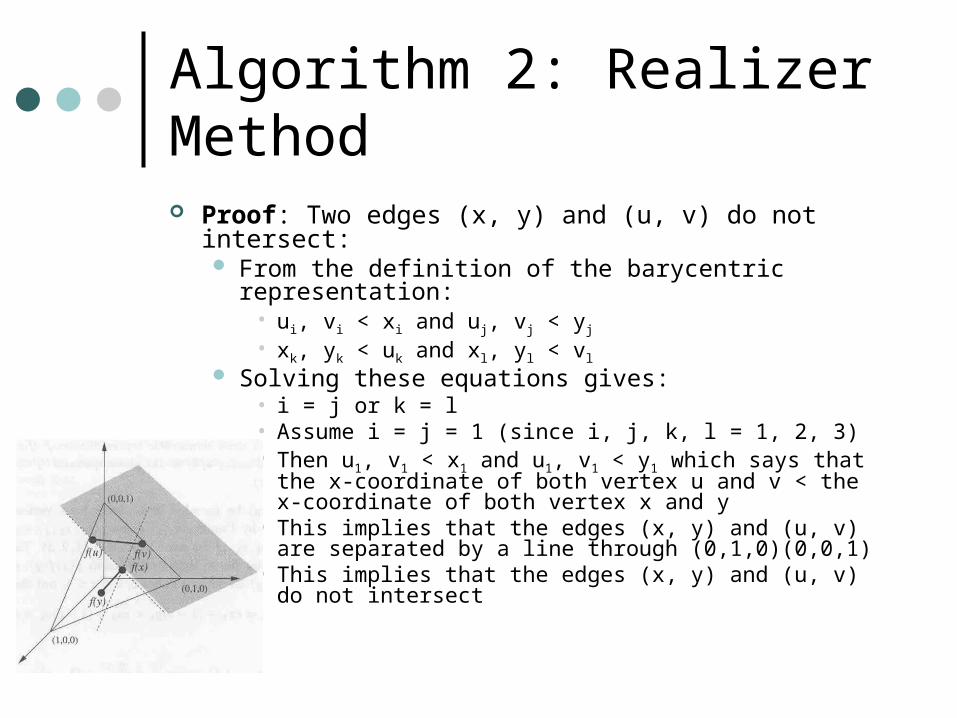
Proof: Two edges (x, y) and (u, v) do not intersect: From the definition of the barycentric representation:
• ui, vi < xi and uj, vj < yj
• xk, yk < uk and xl, yl < vl
Solving these equations gives:• i = j or k = l• Assume i = j = 1 (since i, j, k, l = 1, 2, 3)• Then u1, v1 < x1 and u1, v1 < y1 which says that the x-
coordinate of both vertex u and v < the x-coordinate of both vertex x and y
• This implies that the edges (x, y) and (u, v) are separated by a line through (0,1,0)(0,0,1)
• This implies that the edges (x, y) and (u, v) do not intersect

Algorithm 2: Realizer Method
Thus Barycentric Representation gives a Straight Line Drawing Grid size is (2n – 5) x (2n – 5)
Using a Weak Barycentric Representation, the grid size can shrink to (n – 2) x (n - 2)
A Weak Barycentric Representation is again an injective function assigning three values, such that: v1 + v2 + v3 = 1 For each edge (x, y) and each vertex z ≠ x, y there is some
index k (with k = 1, 2 or 3) such that (vk, vk+1) from x and y <lex (vk, vk+1) from z
• Where (a, b) <lex (c, d) is true if a < c or when a = c and b < d Proof: Weak Barycentric Representation gives a Straight
Line Drawing Same idea as proof for normal Barycentric Representation

Algorithm 2: Realizer Method
Step 2: Make a Schnyder LabelingWhat is a Schnyder Labeling?
• An assignment of a label 1, 2 or 3 to all angles of inner facial triangles, such that:
• Each inner facial triangle has an angle labeled 1, another one labeled 2 and another one labeled 3, in a counter-clockwise order
• The labels of the angles at each inner vertex of G form, in counter-clockwise order, a nonempty interval of 1’s, a nonempty interval of 2’s and a nonempty interval of 3’s

Algorithm 2: Realizer Method
Proof: every triangulated plane graph G has a Schnyder Labeling N(x): the set of neighbors of x in G G/(x,y): the graph obtained by contracting edge (x,y)
from G (that is, remove y from G and connect al neighbors from y to x)
Contractible(x, y): whether or not edge (x, y) is contractible. An edge (x, y) is only contractible if N(x) and N(y) share two vertices
Separating Triangle: a triangle in G which has both interior and exterior vertices
An edge (x, y) is contractible if there is no separating triangle containing (x, y), otherwise the resulting graph will no longer be triangulated

Algorithm 2: Realizer Method
Edge contraction examples:

Algorithm 2: Realizer Method
To prove that every graph G has a Schnyder Labeling, first prove that G has a outer vertex a, which has a neighbor x, such that edge (a, x) is contractibleProof by induction on the number of vertices
• Base case: 4 vertices, K4 inner vertex as x• Induction Step: two cases:
• G has no separating triangles containing a edge (a, x) is contractible for any neighbor x of a
• G has a separating triangle T containing a by induction the subgraph inside T has a vertex x such that (a, x) is contractible

Algorithm 2: Realizer Method
Proof: every graph G has a Schnyder Labeling: This is trivial for n = 3 For n ≥ 4, then there exists an inner vertex x adjacent
to outer vertex a, such that edge (a, x) is contractible (previous proof)
Contracting this edge gives a graph which has one node less and (by induction) has a Schnyder Labeling
Take this Schnyder Labeling and perform a reverse edge contraction (that is, adding a vertex), then the Schnyder Labeling can extended to a Schnyder Labeling of graph G
The order in which the vertices are added is given by the expansion sequence
• Canonical Ordering is an expansion sequence

Algorithm 2: Realizer Method
The way in which the Schnyder Labeling is adjusted:

Algorithm 2: Realizer Method
Orientation of an edge: Each edge has two distinct labels at one end
and two identical labels at the other end• Follows from the conditions of the Schnyder
Labeling
The side with the two identical labels is called the “label of the edge”
The edge is oriented in the direction of the “label of the edge”

Algorithm 2: Realizer Method
Proof: the angles at one outer vertex have all label 1, all label 2 for another and all label 3 for the last outer vertex G is triangulated (n – 3) inner vertices and (3n – 9)
inner edges Each inner vertex has three outgoing edges
(condition 2 Schnyder Labeling) Together: 3(n – 3) outgoing edges for all inner
vertices Thus: no outgoing edges leaves a outer vertex, so all
edges incident on a outer vertex are incoming Thus: the angles at outer vertices all have the same
label (definition of the orientation of an edge)

Algorithm 2: Realizer Method
Step 3: Make a Realizer for G What is a Realizer?
• A Realizer of a triangulated graph G is a partition of the inner edges into three sets T1, T2 and T3, such that for each inner vertex v:
• v has an outgoing edge in each of T1, T2 and T3
• The counter-clockwise order of the edges incident on v is:
• Leaving in T1
• Entering in T3
• Leaving in T2
• Entering in T1
• Leaving in T3
• Entering in T2

Algorithm 2: Realizer Method
• Realizer definitions:
• Root ri: the outer vertex of Ti
• Pi(v): the path in Ti from vertex v to the root ri of Ti
• Since Pi(v) and Pj(v) for i ≠ j share only vertex v, the path P1(v), P2(v) and P3(v) divide the graph into three regions R1(v), R2(v) and R3(v)
• Ri(v): the closed region opposite to root ri of Ti

Algorithm 2: Realizer Method
Proof: Realizer is a Weak Barycentric Representation Pi(v): the number of vertices in path Pi(v) Ri(v): the number of vertices in region Ri(v),
which includes both roots and vertices on both paths
ni(v): all vertices in region Ri(v) which are not on the path Pi-1(v)
Then n1(v) + n2(v) + n3(v) = n – 1, since vertex v is in all regions, but also on all path and is therefore never counted

Algorithm 2: Realizer Method
Take function f, which for every vertex v gives: 1 / (n – 1) (n1(v), n2(v), n3(v)) Satisfies condition 1, since n1(v) + n2(v) + n3(v) = n – 1 Also satisfies condition 2
• A lot of math and definitions• This part of the proof is omitted
Conclusion: Weak Barycentric Representation Straight Line
Drawing on a (n – 2) x (n – 2) grid Schnyder Labeling gives a Realizer Realizer is a Weak Barycentric Representation All together: Realizer Method gives a Straight Line
Drawing on a (n – 2) x (n – 2) grid

Algorithm 2: Realizer Method
Example Straight Line Drawing:

Other parts of chapter 4
Special types of graphs can be drawn on smaller grid (than those by the previous two methodes) 4-connected graph: grid of ((n / 2) – 1) x (n /
2) Algorithm of Miura
• Idea:• Use a 4-Canonical Ordering to split the graph G
into two pieces• Draw both pieces inside a triangle• Connect both triangles

Questions?