chapter 4 runoff conveyance - alabama soil & water ... · runoff conveyance diversion (dv)...
TRANSCRIPT

53 Runoff Conveyance
Chapter 4
Runoff Conveyance

54 Runoff Conveyance
This Page
Intentionally
Left Blank

55 Runoff Conveyance
Check Dam (CD)
Description
A small temporary dam constructed across an area
of concentrated flow to pond and slow the water to
reduce channel erosion. Check dams (also referred
to as “ditch checks”) trap only small amounts of
sediment and are not sediment control devices.
Check dams are to be used on internal drainage
ditches, not in “live” streams. Check dams can be
constructed of rock, wattles (sometimes referred to
as tubes or rolls), sand bags, silt fence, or other
materials acceptable to the design professional.
Since check dams are to be installed to intercept
concentrated flows, proper installation is absolutely
paramount for the check dam to function properly
and not fail structurally.
Installation (rock check dam)
• Space the check dams so that the center of each
dam is approximately the same elevation as the
back toe of the upstream dam (Figure CD-2).
• Remove debris and other unsuitable material
from the check dam location.
• Install an 8 oz. non-woven geotextile
underlayment that extends at least 3 feet
upstream and downstream beyond the rock
check dam. Bury and pin the upstream edge of
the geotextile and pin all edges securely with
staples every 10 inches on-center.
• Ensure the proper gradation of riprap is used.
• Construct the dam with side slopes of 2:1 or
flatter.

56 Runoff Conveyance
• Construct the dam with a parabolic top with the
center portion 6 to 12” lower in elevation than
the outer edges so that the flow goes over the
structure and not around the structure.
• If specified, place geotextile on the upstream
face of the dam to increase impoundment
efficiency for low-flow conditions.
• Check finished size, grade and shape for
compliance with standard drawings and
materials list or with specifications, if included
in contract specifications.
• Stabilize the disturbed area with vegetation.
Figure CD-1 Views of a Typical Rock Check Dam

57 Runoff Conveyance
Figure CD-2 Profile of Typical Rock Check Dam
Installation (wattle check dam)
• Install an 8 oz. non-woven geotextile
underlayment that extends at least 3 feet
upstream and downstream beyond the wattle
check dam. Bury and pin the upstream edge of
the geotextile and pin all edges securely with
staples every 10 inches on-center.
• Place the wattle in a “U” shape as shown in
Figure CD-3.
• Staple the bottom of the wattle on 10-inch
centers on each side of the wattle to keep it from
floating during storm events.
• Place wooden stakes in a “t-pee” non-
destructive fashion.

58 Runoff Conveyance
• If two wattles are needed to reach across the
entire width of the channel, overlap the wattles
at least 18 inches.
Figure CD-3 Wattle Check Dam
Figure CD-4 Wattle Check Dam Photo courtesy of AU-ESCTF

59 Runoff Conveyance
Installation (silt fence check dam)
• Install an 8 oz. non-woven geotextile
underlayment that extends at least 3 feet
upstream and downstream beyond the silt fence
check dam. Bury and pin the upstream edge of
the geotextile and pin all edges securely with
staples every 10 inches on-center.
• Install the silt fence in a “V” configuration with
a notch in the fabric to ensure the maximum
depth of flow is no greater than the depth of the
channel.
Figure CD-5 Silt Fence Check Dam Cross-Section

60 Runoff Conveyance
Figure CD-6 Silt Fence Check Dam Plan View
Figure CD-7 Silt Fence Check Dam

61 Runoff Conveyance
Installation (sand bag check dam)
• Install an 8 oz. non-woven geotextile
underlayment that extends at least 3 feet
upstream and downstream beyond the sand bag
check dam. Bury and pin the upstream edge of
the geotextile and pin all edges securely with
staples every 10 inches on-center.
• Ensure the sand bags are properly oriented in an
alternating stacking pattern.
Figure CD-8 Sand Bag Check Dam Cross-Section
Figure CD-9 Sand Bag Check Dam Plan View

62 Runoff Conveyance
Maintenance
• After rainfall events check the practice and
channel for displacement and erosion and make
repairs as needed.
• If channel erosion exceeds expectations, consult
with a qualified design professional.
• Remove sediment before it reaches a depth of ½
the original dam height.
• Remove check dams when their useful life has
been completed. Stabilize the area where check
dams are removed with vegetation.

63 Runoff Conveyance
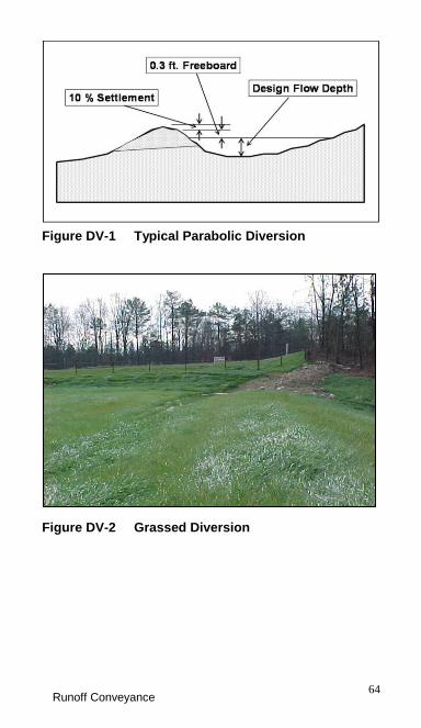
Diversion (DV)
Description
A temporary or permanent ridge and channel
constructed on a stable grade and stabilized with
vegetation. The practice is used to protect a
downslope area by intercepting and carrying excess
water to a stable outlet
Installation
• Begin by ensuring that the diversion outlet is
stable.
• Layout the diversion from the outlet according
to the design grade and planned location.
• Construct the diversion ridge by compacting
earthfill in 6” to 8” lifts, overbuilding 10% for
settlement.
• Check to ensure design dimensions are
obtained.
• Stabilize the diversion with vegetation.
Maintenance
• Inspect after runoff events.
• Remove debris and sediment buildups in the
diversion channel and repair erosion in the
channel bottom.
• Rebuild the ridge to design elevation where
needed.
• Check outlet for damage and repair if needed.
• Mow and fertilize vegetation.
• Remove temporary diversions after service and
stabilize the area with permanent vegetation.
64 Runoff Conveyance
Figure DV-1 Typical Parabolic Diversion
Figure DV-2 Grassed Diversion

65 Runoff Conveyance
Grass Swale (GS)
Description
An earthen channel constructed on a stable grade
and stabilized with vegetation. The practice is used
to provide an area for non-erosive concentrated flow
after runoff events while carrying the water to a
stable outlet.
Installation
• Ensure that the grass swale outlet is stable.
• Layout the grass swale from the outlet
according to the planned location and the design
grade limitations.
• Ensure that lateral surface drainage into the
grass swale is not blocked.
• Ensure design dimensions are obtained. Most
grass swales have a parabolic cross-section but
may be designed to be triangular or trapezoidal.
• Stabilize the grass swale with prescribed
vegetation prior to large runoff events.
• Swales may require the use of an erosion
control blanket or turf reinforcement mat to aid
in establishing vegetation.
Maintenance
• Permanent water in a grass swale will destroy
the vegetation and other conveyance measures
may be required.
• Inspect after runoff events.
66 Runoff Conveyance
• Remove debris and sediment buildups in the
swale, and repair erosion, low spots, and
breaches.
• Check outlet for damage and repair if needed.
• Mow and fertilize vegetation.
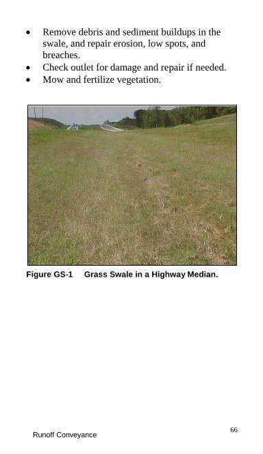
Figure GS-1 Grass Swale in a Highway Median.

67 Runoff Conveyance
Lined Swale (LS)
Description
A constructed channel with a permanent lining
designed to carry concentrated runoff to a stable
outlet. A lined swale is used when vegetation
cannot control erosion and riprap is undesirable.
The lining may consist of concrete, manufactured
concrete products, or turf reinforcement mat (TRM).
Installation
Concrete-lined swale is the only lined swale
covered in this edition of the Field Guide. Refer to
plans and specifications or manufacturer’s
requirements for installation of other linings.
• Layout the lined swale according to plans and as
close to a linear alignment as possible.
• Prepare the location for the concrete-lined swale
by removing debris and obstructions.
• Remove soft sections or unsuitable materials
from foundation and replace with suitable
material.
• Compact foundation soil and excavate cutoff
walls to the required subgrade dimensions.
• Construct concrete forms for swale, inlet, and
outlet according to plans.
• Utilize construction joints every 10 ft. and
expansion joints at least every 20 ft.
• Moisten subgrade prior to concrete placement.
• Refer to plans and specifications or ACI
standards for concrete placement procedures
during weather extremes.

68 Runoff Conveyance
• Place concrete (minimum 3,000 psi) to
thickness required on plans (minimum 4 inches)
utilizing surface vibration.
• As soon as finishing work is complete, cover
surface of concrete with curing compound.
• Remove forms when specified.
• Stabilize areas adjacent to lined swale with
permanent vegetation.
Maintenance
• Inspect at regular intervals and after storm
events.
• Check for erosion adjacent to the channel, at
inlets and outlets and underneath the lined
channel.
• Remove debris and sediment buildups in the
swale and repair any damaged areas.
Figure LS-1 Concrete Lined Swale

69 Runoff Conveyance
Outlet Protection (OP)
Description
Measures installed to prevent erosion at the outlet of
a channel or conduit by reducing the velocity and
dissipating the energy. Outlet protection measures
can be riprap-lined aprons, reinforced concrete
flumes with concrete baffles, or reinforced concrete
boxes with chambers or baffles. Some outlet
protection devices are pre-manufactured.
Installation
• Prepare subgrade for structure by removing
organic material and debris from work area.
• Fill low spots with clean non-organic fill,
compact to density equal to surrounding
material, and grade to lines and grades in plans.
• Maintain a straight alignment, if possible, or
construct any curve needed in the upstream
section of the structure.
• For riprap structures, install non-woven
geotextile meeting specifications over the
completed subgrade. Bury edges of geotextile to
ensure water cannot flow under the fabric.
• Avoid damage to the geotextile when placing
riprap with equipment.
• Construct the riprap apron on zero grade, with
no overfall at the outlet end.
• For concrete structures, install steel
reinforcement at the position shown in the
plans.

70 Runoff Conveyance
• Place concrete in sturdy wood or metal forms,
properly supported to prevent deformation.
• Consolidate concrete using mechanical
vibrating equipment supplemented by hand-
spading, rodding or tamping.
• Avoid concrete placement in inclement weather
and temperature extremes. If extremes cannot
be avoided, follow ACI guidelines for concrete
placement in extreme temperatures.
• Cure concrete according to specifications.
• Do not remove forms prior to the specified
curing time.
• Immediately after construction, stabilize
disturbed area adjacent to the structure with
vegetation.
• Check finished structures for conformance with
designed lines, grades, and quality.
Maintenance
• After storm events, check riprap structures for
erosion around and beneath the riprap and for
rock displacement. Repair and replace the riprap
as needed.
• Check concrete structures for structural cracks
and movement. Repair as needed.
• Remove excessive vegetation, sediment, or
debris.

71 Runoff Conveyance
Riprap-Lined Swale (RS)
Description
A natural or constructed channel with an erosion-
resistant rock lining designed to carry concentrated
runoff to a stable outlet.
Installation
• Remove brush, trees and other debris from the
channel area.
• Excavate the subgrade for the riprap lining to
the designed lines and grades.
• Install geotextile fabric or gravel for a filter
between the subgrade and riprap. Fabric or
gravel should conform to specifications.
• Place riprap to the thickness, depth and
elevations shown in the design.
• Use only stone meeting the gradation and
quality specified in the plan.
• Blend the finished rock surface with the
surrounding ground to prevent overfalls,
channel constrictions or obstructions to flow.
• Stabilize channel inlet and outlets.
• Stabilize surrounding disturbed areas using
vegetation after construction is completed.
• Check finished grades and cross sections
throughout channel length, verifying
dimensions to avoid flow constrictions.

72 Runoff Conveyance
Maintenance
• Check channels after storm events for rock
displacement, sediment accumulations, and
erosion beneath the rock.
• Check for erosion at the inlet and outlet of
channel.
• Check side inlets for erosion.
• Repair and replace riprap as needed.
Figure RS-1 Hand Placing Riprap.

73 Runoff Conveyance
Temporary Slope Drain (TSD)
Description
A pipe used to carry concentrated runoff water
down a slope without causing erosion. The pipes
are used when runoff water from an upper site needs
to be temporarily conveyed down a slope before the
permanent drainage structures can be installed.
Installation
• Remember that pipes are sized according to the
drainage area. If not included in the plans, use
the following table for pipe sizes:
Table TSD-1 Temporary Slope Drain Pipe Sizes
Maximum Drainage Area (Acres)
Pipe Diameter (D) (Inches)
0.5 12
1.5 18
2.5 21
3.5 24
5.0 30
• It is best to install the pipe before runoff water
is conveyed to the pipe.
• Install the pipe with the specified watertight
joints and with a flared inlet section.
• Make sure the inlet section is low enough in
elevation to ensure that surface water can be
directed to the inlet.

74 Runoff Conveyance
• Ensure the pipe is securely anchored to the
slope according to plans or by using a “t-pee”
staking.
• Extend the drain beyond the toe of the slope and
adequately protect the outlet from erosion.
• Install rock or other appropriate outlet
protection (see Outlet Protection Practice).
• Construct the diversion at the top of the slope
according to plans so that surface runoff can be
directed into the pipe. Provide positive grade in
the pipe under the ridge.
• Good compaction of the diversion around the
pipe is essential to avoid piping failure and
blowouts.
• Establish temporary vegetation.
Maintenance
• Inspect the pipes after runoff events. Remove
debris, repair erosion, and repair pipe as needed.
• Check conduit for evidence of leaks or
inadequate anchoring.
• Check the outlet for erosion and sedimentation.
• Make sure that runoff is not bypassing the inlet.
• Check for evidence of overtopping, piping or
uplift.
• Check for bends in conduit. Re-anchor as
needed.
• Remove slope drains when they are no longer
needed and stabilize the area with vegetation.

75 Runoff Conveyance
Figure TSD-1 Temporary Slope Drain

76 Runoff Conveyance
This Page
Intentionally
Left Blank