chapter 4: field inspection, data collecting, report ...field inspection, data collecting, report...
TRANSCRIPT
Bridge Inspection Handbook 4-1 Field Inspection, Data Collecting, Report Writing and Report Review
CHAPTER 4 FIELD INSPECTION, DATA COLLECTING, REPORT WRITING AND
REPORT REVIEW 4.1 INTRODUCTION In this chapter, MassDOT policies and procedures for performing bridge inspections are presented. This chapter will also discuss conducting the field inspections, data collecting, report writing and report review. In addition, the policy for reporting and addressing “Critical” findings is outlined. As mentioned in Chapter 3, inspections performed in Massachusetts are “hands on”, and all inspections are performed by NBIS qualified Team Leaders with the assistance of one or more team members. Bridge inspections and inspection reports that are developed are essential for protecting lives and for protecting the public's investment in bridge structures. The Bridge Inspection Management System (4D) includes the reports that correctly and efficiently evaluate the condition of a structure. This information is also a valuable aid in establishing maintenance and replacement priorities. Finally, inspection reports are stored in 4D and are also used for determining a structure's load carrying capacity. The information necessary to make these determinations must come largely from the bridge inspection reporting system. The importance of the reporting system cannot be over emphasized as the success of any bridge inspection program is dependent upon its reporting system. A new inspection report shall be created each time a bridge is inspected. To achieve maximum effectiveness, each report should be supplemented with sketches, photographs, or any other additional explanatory information. Reports and supplemental information must be accurate, and descriptions or explanations shall be clear and concise. 4.2 STANDARD INSPECTION REPORT FORMS The standardization of the inspection forms is a necessary step for a uniform bridge inspection reporting system. Prior to performing inspections for MassDOT, one should be aware of the standard inspection report forms available in the 4D system. In Chapter 3, the types of inspections commonly performed were briefly explained. Standardized forms have been created to assist in the report preparation and review process. These forms also provide a uniform method for querying information pertaining to the elements and sub-elements of a structure for prioritization of maintenance repairs. The Standard Inspection Forms used are:
Initial Inspection Report Routine Inspection Report Routine Arch Inspection Report Routine Culvert Inspection Report Routine Underwater Inspection Report Routine Segmental Box Girder Inspection Report* Other Inspection Report Routine Movable (Mechanical/Electrical) Inspection Report* Routine Closed Inspection Report Special Member Inspection Report Routine & Special Member Inspection Report
Bridge Inspection Handbook 4-2 Field Inspection, Data Collecting, Report Writing and Report Review
Fracture Critical Inspection Report Damage Inspection Report Divers Activity Report Underwater Special Member Report Underwater Low Clearance Report Element Level Inspection Report (AASHTOWare Bridge Management)
* Not available in 4D.
4.3 SI&A SHEET The Structure Inventory and Appraisal (SI&A) sheet is a tabulation of pertinent elements of information about an individual structure. It includes data that is required by the Federal Highway Administration (FHWA) to effectively monitor and manage the National Bridge Program. Such data is submitted annually to the FHWA and comprises the National Bridge Inventory database. The SI&A sheet also includes information specific to the needs of MassDOT. There are three formats available on 4D for the SI&A sheet. The three formats are:
1. Inventory 2. For Inspection 3. MA Specific
The first two formats are very similar but have certain unique items. The “For Inspection” format includes accessibility information while the “Inventory” format includes projected future project costs. In most cases the “For Inspection” format should be used, which is the default format within 4D. The “MA Specific” format, as it suggests, is a collection of data utilized by MassDOT. The SI&A sheet is not an inspection form but it is to be included with each inspection report submission. Bridge inspection personnel shall become familiar with all of the data items appearing on the SI&A sheet. Descriptions and explanations of the FHWA required data are provided in the FHWA’s Recording and Coding Guide for the Structure Inventory and Appraisal of the Nation’s Bridges. Massachusetts specific items are described in MassDOT’s Supplemental Coding Guide included in Chapter 9. Responsibility for the accuracy of the data appearing on the SI&A sheet is shared between the Boston Bridge Inspection Headquarters and the District Bridge Inspection Units. A clarification of which items are to be confirmed/revised and by who is provided in Chapter 9. 4.4 ELEMENT LEVEL INSPECTIONS Element Level Bridge Inspection Data (ELBID) (formerly PONTIS Core Element Data) is to be collected and entered into the BIMS (4D) with every Routine Inspection. Also, when requested by the District Bridge Engineer to perform an inspection outside of the established frequency, for the documentation of repairs performed on the structure a revision to the ELBID shall be performed. A hard copy of the Element Level Data is to be attached to the inspection report. Please refer to the AASHTO Guide Manual for Bridge Element Inspection.
Bridge Inspection Handbook 4-3 Field Inspection, Data Collecting, Report Writing and Report Review
Bridge elements to be collected include National Bridge Elements, Bridge Management Elements and Agency Developed Elements as appropriate. Typically, quantities for each bridge element shall be calculated during the Initial Inspection. Ideally the quantities will be calculated from the as-built plans. At each Routine Inspection, the Team Leader is to identify the quantity of each bridge element that can be categorized as being in each of the four condition states. Guidelines for the assessment of conditions for each condition state can be found in the AASHTO Guide Manual, see Attachment 4-1 for a quick reference guide for the Element Level Condition States. For bridges that have an underwater inspection, the Team Leader is to also include Element Level Bridge Data collected by the Dive Team. At the time of publication of this Handbook, the underwater inspectors do not have the capability of inputting the Element Level Data into 4D. It is of the utmost importance that Element Level Inspection Data mirrors the NBI condition ratings for each inspection report submission. The Element Level evaluation is to be reviewed by the DBIE and the ABIE with as much scrutiny that the NBI inspection report receives to assure consistency in the reporting. The information contained in the Element Level Data is utilized by MassDOT in assessing the placement of structures on the Bridge Prioritization Model. 4.5 FIELD INSPECTIONS All inspections performed shall be by Teams lead by Team Leaders, where at least two inspectors are on the site at all times, for safety reasons. It is understood that at times additional data or clarification may be required after the bulk of an inspection has been completed, and a team leader may visit the site for clarification as long it is safe do so. The Team Leader (TL) is the principle person in charge of the inspections. Work assigned by the TL during the inspection to the team members is ultimately the responsibility of the Team Leader. 4.5.1 Field Inspection for Initial Inspections Initial Inspections are to be performed on the following: completed structures after they have undergone rehabilitation; newly constructed structures; or structures being added to the inventory for the first time. It is understood, that during an Initial Inspection of a structure, the inspection team shall thoroughly examine all elements and state any irregularities observed in the Initial Inspection report. The secondary purpose of this inspection is to document the “as built” condition. Inspectors should also document any details in the main carrying members that differ from the construction drawings. At a minimum the following shall be evaluated: beams should be evaluated for vertical alignment (plumb) and the presence of camber both positive and negative; if bearings exist they should be evaluated based on the type of bearing system present; guardrail and bridge railing alignment should be checked for both vertical and horizontal alignment; curb reveal measurements and locations where measurements were taken shall be obtained; substructure elements should be checked for vertical alignment. Photos of the elements above shall be stored as part of the history file for reference in the future to evaluate changed conditions when encountered.

Bridge Inspection Handbook 4-4 Field Inspection, Data Collecting, Report Writing and Report Review
For non-dive bridges it will be necessary to take stream bed profiles at both the upstream and downstream fascia to obtain an as built profile. This could be used in the future to determine if a scour is occurring and re-evaluation of Item 113 is required. Above water inspectors are to take the measurements. In some cases the measurements can be taken with drop lines from the bridge deck. If stream flow is too swift for drop lines other methods may be required. The data can be presented in chart form or in graph form or both. Points of measurement and elevation references must be clearly stated. Whatever method is chosen for use, it is important that it be repeatable from cycle to cycle. The value of the information is in the comparison from inspection to inspection to recognize major bed changes. 4.5.2 Field Inspection for Special Member Inspections Team Leaders shall give Special Member Inspections their highest priority in their monthly scheduling. As such, every attempt shall be undertaken to perform Special Member inspections at the beginning of every month. If a Special Member Inspection is to be done in conjunction with a Routine Inspection, then both the Routine and Special Member Inspections shall be attempted to be completed at the beginning of the month. The documentation of repairs performed on a structure shall be reported in the Special Member Inspection Report. As previously mentioned, Section 4.4, the ELBID shall also be updated and included in the submission of the inspection report. Team Leaders shall be cognizant to inspect all structural components of a Special Member Element. For example, if the Special Member on a structure is for Item 59.4; Girders or Beams, and the inspection is to inspect the girder ends of 2 particular girders, then it shall be expected that the Team Leader will not only inspect the 2 particular girder ends, but shall inspect and document the deficiencies on all girders and beams for that particular detail and surrounding environment. 4.5.3 Field Inspection for Damage Inspections Upon notification of an Incident, the DBIE shall dispatch an Inspection Team to the structure. The DBIE shall then concurrently notify the District Bridge Engineer and the Area Bridge Inspection Engineer. The Area Bridge Inspection Engineer will then notify the Bridge Inspection Engineer, who in turn will notify the State Bridge Engineer. The District Bridge Engineer, DBIE and inspection staff should be aware that a request for incident response may occur at any time of day or night. Damage Inspection for verification of reported damage does not require extensive in-depth inspection of all members of the structure, but a cursory investigation to observe if the reported damage has affected other components or if damage is hiding or causing other damage or overstress. In addition, inspection should cover areas other than the immediate area of damage impact. This means Inspectors must assess the interconnectivity of the bridge elements to determine the paths that the initial impact force could have taken to inflict damage to other elements. Inspectors shall inspect and identify members or areas where items are disconnected or loose and could vibrate free, and are removed or directed to be removed by appropriate forces. For example, diaphragms can transmit the initial impact force to other interior beams, causing localized damage around the diaphragm connections. Also, when reporting the information from a damage inspection, the inspector must obtain measurements to a known referenced fixed point on the structure.

Bridge Inspection Handbook 4-5 Field Inspection, Data Collecting, Report Writing and Report Review
When damage is verified and deemed to be a danger to pedestrians and/or vehicles, the site shall not be left unattended until the custodial owners have arrived and are preparing to respond with the necessary safety precautions. The Inspection Team shall document the safety precautions implemented in the Damage Inspection Report. In situations where a repair cannot be performed immediately, after the appropriate maintenance forces have installed the hazard prevention devices, the District Bridge Inspection Engineer, with the concurrence of the District Bridge Engineer, shall establish a schedule for inspection to monitor and verify that the barricades and hazard prevention devices have not moved and are still effective until the danger has been resolved. When a damage incident is reported by the District, and the Inspection Team has responded, inspected and written the Damage Inspection Report, the time associated with those activities shall be charged to the Reimbursable Cost Code generated by the District for that particular incident, if one has been generated. 4.5.4 Field Inspection for Scour Critical Structures For bridges that have been determined to be Scour Critical it will be necessary to take stream bed profiles at both the upstream and downstream fascia to comply with the FHWA mandated Scour Plan of Action (POA). Scour Critical bridges have a numerical coding for Item 113 of 3 or less. For bridges that have underwater inspections, the stream bed profiles will be obtained by the Underwater Inspection Unit as part of their inspection. For non-dive bridges, the above water inspectors are to take the measurements. In some cases the measurements can be taken with drop lines from the bridge deck. If stream flow is too swift for drop lines other methods may be required. The data can be presented in chart form or in graph form or both. Points of measurement and elevation references must be clearly stated. Whatever method is chosen for use, it is important that it be repeatable from cycle to cycle. The value of the information is in the comparison from inspection to inspection to recognize major bed changes. 4.5.5 Plan of Inspection In order to make the inspection as orderly and systematic as possible, the inspector should plan the inspection in advance. The plan shall include the review of previous inspections; load rating report; fracture critical procedures (if applicable); and SI&A. In addition, a plan includes determining the appropriate inspection sequence, establishing a time schedule, preparing for special inspection requirements (e.g. non-destructive testing and underwater inspection), organizing the field notes, anticipating the effects of traffic control procedures, and facilitating a thorough and complete inspection. Prior to the actual inspection of a structure, the inspection team leader shall coordinate any and all parties (i.e.; RR flaggers, Police details, traffic set up, etc.) that may be required to accomplish the inspection. It is advisable that the team leader scope the bridge prior to the inspection to evaluate entry points, means of inspection, and any other aspects that may be required to inspect the structure. The Team Leader shall be aware of the data needed for the particular inspection being performed. At times special requests are made and it is essential that all data is collected during the inspection. Once the Team Leader has reviewed the Load Rating Report, he/she may feel that a new rating may be warranted. In such cases the inspection will require in depth documentation and additional time to complete for the

Bridge Inspection Handbook 4-6 Field Inspection, Data Collecting, Report Writing and Report Review
preparation of a new load rating. Discussions with the District Bridge Inspection Engineer should occur so that other scheduled inspections get reassigned if needed. 4.5.6 Orientation The orientation and numbering of bridge elements should be as shown on the plans whenever available. When plans are not available the rating report should be used. If no rating report exists, then the numbering of piers, beams, etc. shall be orientated from west to east, or from south to north. It is important that the orientation of each element be clearly established. Orientation for rivers and streams is looking downstream. That is the left bank is on your left as you face downstream and the right bank is on your right as you face downstream. For tidal rivers, downstream is in the direction of the ebb (outgoing) tide. Some examples:
Identify substructure units (abutments) and sides of floorbeams, such as north/south or east/west designations; alternately, number the substructure units (piers) such Pier #3
Sides of members can be identified by direction (e.g. "south side of floorbeam #2" or "north side of Pier #4")
Span numbers and bay numbers should be used to identify general areas on the bridge, as shown on plans or as established otherwise
Upstream or downstream designations can be assigned to structures over waterways (e.g., "upstream truss", "downstream girder", or "upstream arch")
For truss elements, identify the member with joint designations If the orientation used during the inspection differs in any way with that used in existing documents, these differences shall be clearly stated in the inspection report under the general remarks section of the inspection report. 4.5.7 Condition Information To ensure a comprehensive condition inspection and as a part of the requirements of record keeping and documentation, an inspector shall record the type, size, quantity, severity and location of deterioration and deficiencies for each applicable element in a given component. The Bridge Inspectors Reference Manual (BIRM) and the Manual for Bridge Evaluation (MBE) are the inspectors’ guide for identifying the members and the deficiencies on a variety of structure types. The condition rating guidelines contained in the 1995 Recording and Coding Guide for the Structure Inventory and Appraisal of the Nation's Bridges (or most recent) are to be used in the evaluation of the deck, superstructure, and substructure. During the inspection, the inspector shall be aware of items in the SI&A that must be verified and updated, should it be required. The outcome of the inspection shall always be to provide a clearly presented narrative description of the conditions. Inspectors shall note the following: all signs of distress, failure, or defects with sufficient accuracy so that another inspector at a future date can make a comparison of condition or rate of deterioration; load, speed, or traffic restrictions on the bridge; information about high water marks and unusual loadings, the presence of any negative camber on any elements, and section losses to beam ends.

Bridge Inspection Handbook 4-7 Field Inspection, Data Collecting, Report Writing and Report Review
All work or repairs to the bridge since the last inspection should be documented. If work is undertaken on a structure that improves the physical condition of a structure and results in the Team Leader increasing the numerical value of an element, the Team Leader must explain what work was undertaken to improve the condition. Verify or obtain new dimensions when maintenance or improvement work has altered the dimensions of the structure. The end result of the inspection performed is to ensure the public that a safe structure is in place to carry traffic. The data collected on defects found helps with the determination of the safe load carrying capacity of the structure. The documentation will assist the custodian of the structure with important information for the proper maintenance and rehabilitation information. Consistency in coding, data collection and documentation is discussed in subsequent sections. 4.5.8 Critical Inspection Findings Deficiencies are occasionally discovered during bridge inspections that require immediate action. They can be structural in nature such as a severely undermined girder bearing or they may present a hazardous situation to the travelling public. When such deficiencies are discovered a special procedure of notification is warranted as explained below. 4.5.8.1 Critical Structural (CS/I) Definition and Notification If a deficiency is discovered that may affect the structural integrity of the bridge, it is considered a Critical Structural Deficiency. A Critical Structural Deficiency is defined as a deficiency in a structural element of a bridge that poses an extreme unsafe condition due to the failure or imminent failure of the element which will affect the structural integrity of the bridge. Because of the critical nature of the deficiency the urgency code must be Immediate. To assure an immediate response the details of the deficiency must be transmitted quickly. During an inspection, if an inspector discovers a Critical Structural deficiency, the inspector shall immediately notify the DBIE, or in his absence, the DBE. For more information, refer to Section 4.7 of this Handbook regarding CS/I documentation. 4.5.8.2 Critical Hazard (CH/I) Definition and Notification If a deficiency is discovered that poses an extreme hazard or unsafe condition to the public, it is considered a Critical Hazard. A Critical Hazard condition is defined as a deficiency in a component or element of a bridge that poses an extreme hazard or unsafe condition to the public, but does not impair the structural integrity of the bridge. Because of the critical nature of the deficiency the urgency code must be Immediate. To assure an immediate response the details of the deficiency must be transmitted quickly. During an inspection, if an inspector discovers a Critical Hazard deficiency, the inspector shall immediately notify the DBIE, or in his absence, the DBE. For more information, refer to Section 4.7 of this Handbook regarding CH/I documentation. 4.5.9 Request for Re-Evaluation of Item 113 - Scour Critical Bridges The Team Leader must be aware, able to recognize and document changes that are occurring in the stream bed in the vicinity of the structures. These changes, documented by inspections, are to be used to assist the DBIE in determining if the request for a re-evaluation of Item 113 - Scour Critical Bridges is necessary. A re-evaluation does not just apply to structures with Item 113 less than or equal to a
Bridge Inspection Handbook 4-8 Field Inspection, Data Collecting, Report Writing and Report Review
numerical rating of 3. A re-evaluation may be necessary for structures with Item 113 greater than a 3. If a re-evaluation is required, then the Bridge Scour – Item 113 Re-evaluation Form will be filed out and submitted to the Area Bridge Inspection Engineer, see Attachment 4-2. Some concerns the Team Leader shall be aware of and document are as follows:
Channel changing course Evidence of erosion or scour around footings and embankments Large amounts of debris around the substructure Evidence of rip rap, bank protection removed or altered Stream work performed by others that might change the hydraulic characteristics at the bridge
All of the concerns mentioned above could result in a request for a re-evaluation. In Summary, a request for an Item 113 re-evaluation shall be submitted for the following cases
When a structure over water has been replaced Substructure scour repairs performed and/or streambed scour countermeasures have been
installed on a structure that is scour critical Significant changes mentioned above have occurred that alter the stream bed or flow
characteristics of the waterway 4.5.9.1 Structure over Water That Has Been Replaced When a structure over water has been replaced, the DBIE will be required to forward the Initial Inspection to the ABIE who will then submit the report to the Bridge Engineer for an initial coding of Item 113. 4.5.9.2 Substructure Scour Repairs Performed and/or Stream Bed Scour Countermeasures Installed When a structure is scour critical and has had scour repairs performed on the substructure and/or stream bed scour countermeasures have been installed, the DBIE will be required to forward the Inspection that documents the improvements to the ABIE, who will then submit the report to the Bridge Engineer for re-evaluation of Item 113 coding. 4.5.9.3 Stream Bed or Waterway Changes The Team Leader shall compare the stream bed profiles being collected and waterway changes to what was documented in past inspections. The loss of the stream bed material, or change in flow characteristics may warrant the re-evaluation of the Item 113 to ensure proper coding and structural stability. The DBIE will submit these Inspection Reports with the documented findings on the streambed changes to the ABIE who will submit the report to the Bridge Engineer for re-evaluation of Item 113 coding. 4.5.10 Reporting of Structurally Deficient Bridges When a Team Leader inspects a structure and observes a condition that warrants a lowering of the numerical condition coding of a structure to a 4, or from a 4 to a 3, for Item 58, Item 59, Item 60, or Item

Bridge Inspection Handbook 4-9 Field Inspection, Data Collecting, Report Writing and Report Review
62, they shall notify the District Bridge Inspection Engineer. Preferably, this notification shall be done while the Team Leader is still at the structure, so as to allow the DBIE the opportunity to come to the structure to observe and concur with the Team Leader’s decision. The intent of notifying the DBIE would be to ensure Items 90 thru Item 92 are coded in a timely manner so that the next inspection is undertaken. 4.5.11 Other Information Gathered at Routine Inspections 4.5.11.1 Request for Rating or Re-rating The Team Leader shall be responsible for recommending a rating request or a re-rating request for a structure. This recommendation shall be stated in the request for rating or re-rating block located on the 2nd page of the Routine Inspection Report or 1st page of a Special Member Inspection Report. The Team Leader shall evaluate the deficiencies observed on the structure and any alterations made to the structure, in relation to the previous rating report, which would warrant a recommendation to rate or re-rate a structure. 4.5.11.2 Curb Reveal Measurements The average curb reveal measurement should be used in documenting the curb reveal on the inspection report. The curb reveal measurement is taken primarily to identify if additional pavement material has been added to the structure since the last inspection. The measurement should be made to the nearest 10 mm. If there is no curb, then a measurement should be taken from the parapet, either the top or lowest break line and the point of reference should be clearly defined so that future measurements can be repeated. The reference point shall be stated in the curb comments of the inspection report. 4.5.11.3 Vertical Clearance Measurements & Vertical Clearance Signage Verification Inspection Teams are required to check the low point vertical height clearances under a bridge, or through a bridge in the case of thru truss bridges, or both. The low point clearance is taken within the traveled way. The travel way is defined as the roadway lane that is allowing travel on a regular basis. Team Leaders should use their judgment when accessing a roadway traveled way. For example, if a roadway has a breakdown lane that travel is permitted on a regular basis, then the clearance will need to be verified at the outer limits of the breakdown lane. Team leaders should not adjust clearance measurements because the travel way is being altered for the convenience of a construction project. Vertical clearances shall be taken during every routine or damage inspection performed. However, it is understood that it should not be different unless a change condition has occurred to the wearing surface below the structure or on the structure as in the case of a thru truss bridge. This verification frequency will ensure accuracy of the data being recorded at the time of the inspection. The location of the low point(s) should be clearly identified on a framing plan incorporated into the inspection report, see Attachment 4-3. Team Leaders shall place a note in the general remarks when they do not verify the vertical clearance and the reason why. When the inspection team field verifies the vertical clearance height is less than 14’-6”, then the team shall verify the placement of any clearance posting signs in the field during the inspection. Note if any of the “advanced” clearance posting signs or “at bridge” clearance posting signs are missing, then the Team Leader shall notify the DBIE of the missing signs and the location of the missing signs.

Bridge Inspection Handbook 4-10 Field Inspection, Data Collecting, Report Writing and Report Review
In relation to the discussion in this article, it is appropriate to define the “At Bridge” and “Advanced” clearance posting sign terms:
At Bridge Clearance Posting Signs: Signs erected immediately in advance of, or on the bridge being posted.
Advance Clearance Posting Signs: Signs placed at approach road intersections or other points where a vehicle which exceeds the posted limits must detour or turn around.
There are no Massachusetts General Law requirements for installing clearance posting signs, however in order for a bridge to be considered properly clearance posted, an At Bridge Sign must be either within visible distance of the structure or attached to the structure and be erected facing each direction of traffic. If there is an intersecting street between the sign and the bridge, an additional sign must be erected immediately adjacent to the bridge. These additional signs must be in place in order for the bridge to be considered properly posted. When the inspection team field verifies that the vertical clearance is equal to or exceeds 14’-6”, then the team leader shall record the measurement and check off the “not applicable” box in the area of the report dedicated for “Clearance Posting” on the inspection report. Further discussion of clearance posting sign procedure is contained in Section 4.8 of this Handbook. 4.5.11.4 Weight Posting Verification & Weight Posting Signage Verification The Team Leader shall review the latest rating report of the structure to be inspected, if one exists, so as to obtain any recommended posting for the structure. The Team Leader shall verify the actual weight posting for the structure in the field and compare it to the recommended weight posting contained in the rating report. The actual and recommended weight posting values shall be stated in the “weight posting” area of the inspection report. If a discrepancy exists between the actual and recommended weight posting recommendation, then the Team Leader shall notify the DBIE of his findings. The Team Leader shall verify the “at bridge” and “advanced” weight posting signs are in place and are accurate for all structure that require posting. Further discussion of the actions to be taken by the DBIE when discrepancies are encountered shall be contained in Section 6.11 of this Handbook. 4.5.11.5 Average Daily Traffic At every Routine Inspection the inspector shall refer to the MassDOT website location to obtain traffic data counts for the structure being inspected. The website is at the MassDOT TransNet site. Click on Highway, then Quick Links, then Departments, under Design and Engineering, click Traffic Data Collection. In the first paragraph there is a link to the interactive map. Zoom in to your area of interest. The map shows where the latest traffic counts have been taken and the year. If there are no traffic counts available on the website, then a manual vehicular and truck traffic count on the structure shall be undertaken. The counts shall be performed and the SI&A shall be marked with the time the counts where taken and number of vehicles observed. The counts can then be calculated using

Bridge Inspection Handbook 4-11 Field Inspection, Data Collecting, Report Writing and Report Review
the formulas and example attached in Attachment 4-4. Other instructions on what will be recorded in Items 29, 30 and 109 of the SI&A are in subsequent sections. The Team Leader should use his/her judgment as to whether or not the traffic counts at the MassDOT website are still relevant. This could depend on how old the count is, whether traffic patterns have changed for the area, etc. If the TL suspects that the counts may not represent current traffic conditions then the team should obtain a manual count as described above. 4.5.11.6 Inventory Photos During the Initial Inventory Inspection, a series of photographs shall be taken to document the structure for inventory purposes. At a minimum, the following views shall be taken:
Two photographs of the roadway on the bridge, one from the approach roadway at each end of the bridge, taken such that the near guardrail-bridge rail transition is clearly visible
Two elevation photographs, one of each elevation of the bridge One photograph of the general underside of the bridge If the bridge is over water, two photographs, one looking upstream and the other downstream
from the bridge If the bridge has any unusual features or characteristics, a photograph should be taken of them for inventory purposes as well. If the bridge has a commemorative plaque, or multiple commemorative plaques attached to the structure, a photograph of each plaque shall be taken and included in the inventory photos. The photo shall be taken directly perpendicular to the plaque with a measured scale, such as a tape measure or folding ruler, placed adjacent to the plaque within the photograph so that its true size can be obtained in case it needs to be duplicated in the future. During the life of the bridge, this series of inventory photographs shall be repeated every ten years unless conditions at the bridge have changed dramatically before the ten year time period is out, rendering the previous set obsolete. These photos shall be saved in the 4D database.
4.5.11.7 Stream Bed Profiles For all bridges over water that are non-dive bridges, the Team Leader will take stream bed profiles measurements at both the upstream and downstream fascia and record this in the inspection reports. In some cases, the measurements can be taken with drop lines from the bridge deck. If stream flow is too swift for drop lines other methods may be required. The data can be presented in a chart form or in graph form, or both. Points of measurement and elevation references must be clearly stated. Whatever method is chosen for use, it is important that it be repeatable from cycle to cycle. The value of the information is in the comparison from inspection to inspection to recognize major bed changes. For bridges that have underwater inspections, the stream bed profiles will be obtained by the Underwater Inspection Unit as part of their inspection.
Bridge Inspection Handbook 4-12 Field Inspection, Data Collecting, Report Writing and Report Review
4.6 INSPECTION DOCUMENTATION and REPORT WRITING 4.6.1 Creation of Inspection Report Team Leaders are responsible for the creation of the inspection report record in the Bridge Inspection Management System (4D). The report record shall be created in the system while the field inspection is occurring. If it is not created while inspection is ongoing it shall be in the system no later than 3 days after the inspection has been completed. It is understood that the creation of this record as a duplicate of the previous inspection is acceptable. In no way will this inspection report be construed as the actual inspection report until the Team Leader has committed the report for review. 4.6.2 Date of Inspection When inspections are performed over multiple days, the start date of the inspection should always be used for the report and SI&A coding. The start date is the date that elements are actually inspected (a recon of a structure shall not be considered as a start date). This is especially important when inspections are started in one month but completed in the next month. When inspections are delayed for access issues such as construction operations or right-of-entry permit acquisition, the inspection team should complete as much of the inspection that is physically possible and complete an inspection report depicting the areas and elements inspected. The report should clearly state the limits of the inspection and explain which areas were not inspected and why. When access for the other areas is granted and/or possible, the TL should then return to the bridge to complete an “Other” inspection with its own date of inspection. 4.6.3 Inspection Defects In the inspection of a structure, a Team Leader may discover faults, flaws and imperfections to the structural elements. These defects should be identified and described by their type, size and location. The Team Leader shall document the defect and describe the seriousness of the defect in the body of the inspection report. If, in the opinion of the Team Leader, an observed defect could receive CORRECTIVE ACTION, then it is to be considered a DEFICIENCY. 4.6.4 Inspection Deficiencies The Team Leader shall assign a deficiency code to any observed defects that require corrective action. A deficiency code consists of a Deficiency Category and an Urgency Code. The complete Deficiency Code is entered in the column adjacent to the sub-elements condition rating on the Routine Inspection Report. The code is similarly entered on Special Member and Fracture Critical Inspection Reports as needed. Deficiencies are classified into four categories. The categories are as follows: M = Minor Deficiency: Deficiencies which are minor in nature, generally do not impact
the structural integrity of the bridge and could easily be repaired. Examples may include but are not limited to: Spalled concrete, Minor pot holes, Minor corrosion to steel, Minor scouring, Clogged drainage, Minor damage to guard rail, etc.
Bridge Inspection Handbook 4-13 Field Inspection, Data Collecting, Report Writing and Report Review
S = Severe/Major Deficiency: Deficiencies which are more extensive in nature and need more
planning and effort to repair. Examples may include but are not limited to: Moderate to major deterioration in concrete, Exposed and corroding rebars, Considerable settlement, Considerable scouring or undermining, Moderate to extensive corrosion to structural steel with measurable loss of section, etc.
C-S = Critical-Structural Deficiency: A deficiency in a structural element of a bridge that poses an
extreme unsafe condition due to the failure or imminent failure of the element which will affect the structural integrity of the bridge. All Critical-Structural Deficiencies need Immediate corrective action.
C-H = Critical-Hazard Deficiency: A deficiency in a component or element of a bridge that poses an
extreme hazard or unsafe condition to the public, but does not impair the structural integrity of the bridge. Examples may include but are not limited to: Loose concrete hanging down over traffic or pedestrians, A hole in a sidewalk that may cause injuries to pedestrians, Missing section of bridge railing, etc. All Critical-Hazard Deficiencies need immediate corrective action.
Urgency codes are classified into three categories. The categories are as follows: P= Prioritize: Shall be prioritized by District Bridge Engineer or the
Responsible Party (if not a State bridge) and repairs should be made when funds and/or manpower available.
A= As soon as possible: Action/Repair should be initiated by District Bridge Engineer or
the Responsible Party (if not a State bridge) upon receipt of the Inspection Report.
I= Immediate Corrective Action: Immediate means that Inspector(s) immediately contact District
Bridge Inspection Engineer (DBIE) to report the Deficiency and receive further instruction from him/her. This level of urgency shall only apply to C-S and C-H deficiencies.
4.6.5 Inspection Dimensioning Sufficient dimensions shall be provided of any deficiencies observed. The dimensioning shall provide actual size measurements and depth measurements to capture the scale of the defect. These measurements shall then be referenced to a fixed and definable reference point on the structure. It is desirable that all reference points refer from the centerline of bearings for the structure. All units of measurement shall be stated in English Units. Inspectors shall measure and record crack sizes found during inspections. They shall record the lengths and widths and depths were possible and reference to the locations of the cracks to a fixed point on the structure.

Bridge Inspection Handbook 4-14 Field Inspection, Data Collecting, Report Writing and Report Review
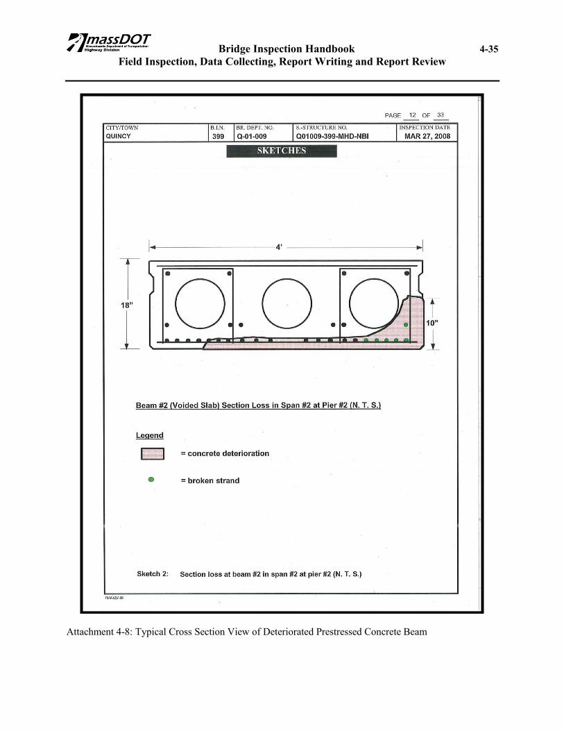
When inspectors discover section loss on structural steel elements (i.e.; girders, stringers, truss elements, or reinforcing bars) they shall measure and state the remaining structural steel available. The inspector shall not assume a section loss percentage, but shall provide measurements of remaining thickness. 4.6.6 Inspection Sketches When inspecting bridges, it may be necessary to use sketches to clarify locations and/or details of defects. When the sketch format is selected for recording bridge inspection results, the information should be recorded systematically. In most cases it will be possible to use reproductions of portions of the plans for the sketches. However, in some instances, such as when the "as built" detail is different from what is shown on the construction drawings, an accurate sketch showing the existing detail will have to be drawn. For examples of typical sketches, see Attachment 4-5: Typical Underside of Deck Condition Sketch, Attachment 4-6: Typical Beam End Elevation Sketch, Attachment 4-7: Typical Beam Elevation Sketch, and Attachment 4-8: Typical Cross Section View of Deteriorated Prestressed Concrete Beam. 4.6.7 Inspection Photos All photographs shall be taken in color with a digital camera. The camera used shall be capable of taking all required photographs in proper focus and sufficient level of detail, whether overall inventory photographs or close-up detail photographs of deficiencies. The camera must also be capable of operating with an adjustable flash unit in order to properly light up dark areas and fine details. It is preferable that the camera will record a date stamp on every image. A photograph should be taken to assist either the written description or sketch of a deficiency. If there are several deficiencies of the same type, a photograph would be taken to show a typical deficiency while sketches would be used to show and dimension each deficiency at each location. When photographing a deficiency, it is usually best to take two photographs, one being a general view of the deficiency which should locate it in relation to the rest of the bridge structure, while a second should be a close up of the deficiency itself, showing its extent and any distinguishing features. This close up view must be in focus, properly lit and should include a ruler to help establish the scale of the deficiency. A pencil, pick or screw driver tip may be used to point to important details that might otherwise be overlooked in the photograph. If a deficiency is being monitored as part of Special Member Inspection, in lieu of repair, every effort should be made to take a new detail photographs from the same location and at approximately same scale as the ones before so that the progress of the deficiency can be readily established. 4.6.8 Videos of Deficiencies In some cases, a deficiency is only apparent when under traffic. For example, the longitudinal joint between butted precast beams may have failed so that the beams are deflecting independently of each other. This situation could only be documented during a live action video of a vehicle going over the bridge. In such cases, the video segment should be shot showing the deficiency in action. The video

Bridge Inspection Handbook 4-15 Field Inspection, Data Collecting, Report Writing and Report Review
should be properly focused, well lit and the view should be framed such that the entire action is kept within the view of the camera without having to move the camera to follow the action. If at all possible, a ruler should be used to establish the scale of the view and deficiency. The video will then be forwarded, via email, to the District Bridge Inspection Engineer, District Bridge Engineer, Bridge Inspection Engineer and the Area Bridge Inspection Engineer. 4.6.9 Condition Coding The numerical condition ratings should characterize the general condition of the entire component
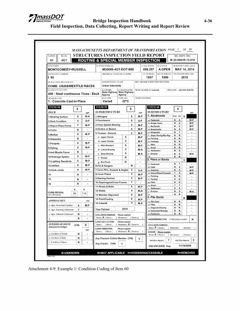
being rated. They should not attempt to describe localized or nominally occurring instances of deterioration or disrepair. Correct assignment of a condition rating must, therefore, consider both the severity of the deterioration or disrepair and the extent to which it is widespread throughout the component being rated. It shall be noted that a bridge's load-carrying capacity is not to be used in the condition coding process. The fact that a bridge was designed for less than current legal loads, and may even be posted, should have no influence upon the condition rating. Narrative descriptions of the conditions should be clearly presented. Note all signs of distress, failure, or defects with sufficient accuracy so that another inspector at a future date can make a comparison of condition or rate of deterioration. When a sub-item is assigned a numerical condition of 6 or less, the inspector will be required to write a narrative description of the defect. Also, if any sub-element is assigned a deficiency coding of S-A, then it will be required that a photo of the sub-element be contained in the inspection report. In relation to Item 60, 61 and 62, the inspection report will have two columns (Dive & Cur) for each sub-element. If a bridge is a Dive (Underwater Inspection) bridge then the inspectors shall import the condition rating of each sub-element from the latest Underwater Inspection Report and place them in the “Dive” column. The Inspector’s own evaluations of these sub-elements are coded in the “Cur” column. Generally, the overall condition of each of the above items is the lower number between Underwater Inspection Report and the Inspector’s Report and that would be the number which is entered in the SI&A. The above water inspector needs to review what is contained in the Underwater Inspection Report and make the determination if the item controlling the Underwater Inspection is valid for controlling the overall condition. Two examples and attachments are provided for clarification as follows: Example #1: The “Abutment” from an Underwater Inspection Report is an “N” and from a Routine
Inspection is a “6”. The “Pier or Bents” from an Underwater Inspection Report is a “7” and from a Routine Inspection is a “5”. The “Pile Bents” from both reports is an “N”, then the overall “Abutment” rating is a “6”, “Pier or Bents” is a “5” and “Pile Bents” is “N”. Overall condition rating of the Item 60 (Superstructure) would be a “5” and this is the number which will be coded in the SI&A. The Routine Inspection condition rating is less than the Underwater Inspection Condition Rating. Refer to Attachment 4-9, Example 1: Condition Coding of Item 60.
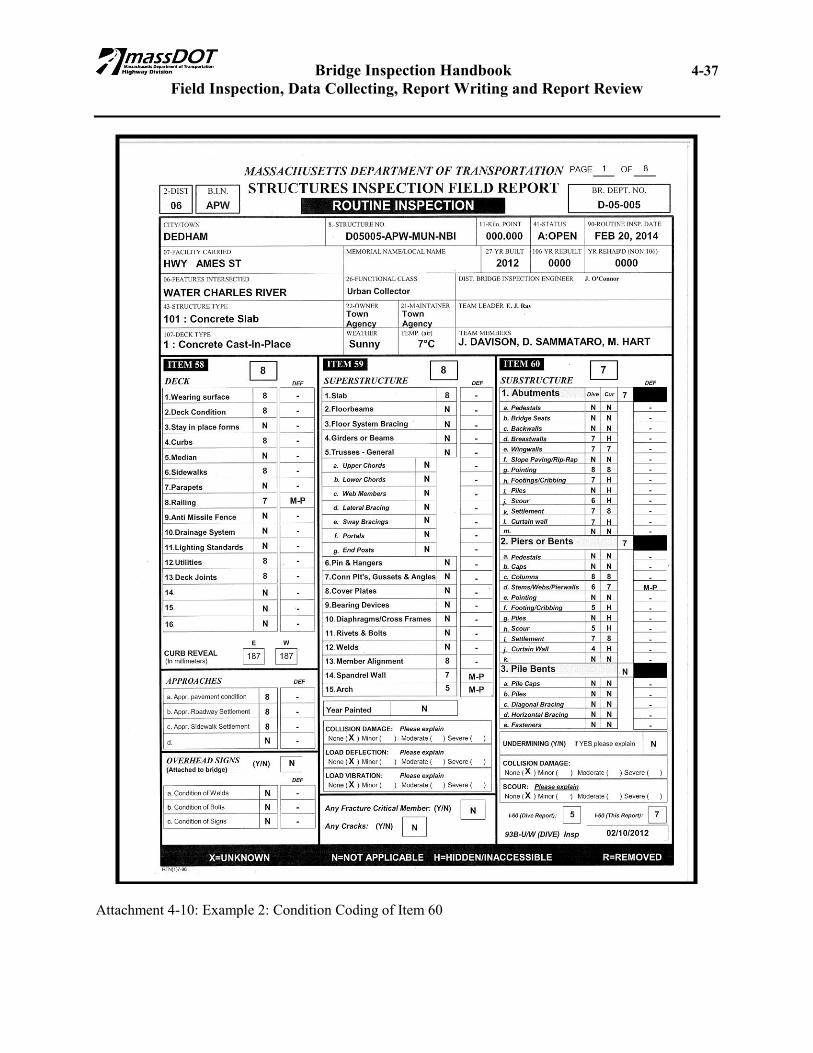
Example #2: The “Abutment” from an Underwater Inspection Report is a “6” and from a Routine
Inspection is a “7”. The “Pier or Bents” from an Underwater Inspection Report is a “5” and from a Routine Inspection is a “7”. The “Pile Bents” from both reports is an “N”, then the overall “Abutment” rating is a “7”, “Pier or Bents” is a “7” and “Pile Bents” is
Bridge Inspection Handbook 4-16 Field Inspection, Data Collecting, Report Writing and Report Review
“N”. Overall condition rating of the Item 60 (Superstructure) would be a “7” and this is the number which will be coded in the SI&A. Although, in this example the Underwater Inspection overall condition rating is a “5” the scour that has occurred does not impact the main load carrying member of this rehabilitated structure. The existing arch structure is remaining but the new structure above the arch is supported on piles. Loads are not being transferred to the arch. Refer to Attachment 4-10, Example 2: Condition Coding of Item 60.
4.6.10 Narrative Presentation The narrative presentation shall be the writing remarks segment of the inspection report summarizing the field inspection findings of the inspection team. The narrative shall begin with the inspector describing the method of orientation selected to orient the reader. The inspector will then write in the “General Remarks” section any load, speed, or traffic restrictions on the bridge, as well as any special means of access utilized to inspect the structure. Include information about high water marks and unusual loadings. Also, all work or repairs to the bridge since the last inspection should be listed. If work is undertaken on a structure that improves the physical condition of a structure, the Team Leader must explain what work was undertaken to improve the condition. Verify or obtain new dimensions when some maintenance or improvement work has altered the dimensions of the structure. When numerous defects are to be documented under a sub-element it is encouraged to do so in “bullet” form. The condition narrative should begin with a summary statement which identifies the general condition and/or highlights the controlling deficiencies that are presented in the bullets which are listed below. Refer to Attachment 4-11 for an example of presenting information in an inspection report. The application of this method of presentation will allow the ease of comparison between successive inspection cycles and allow for the visual progression of the deterioration of the sub element. 4.6.11 SI&A Edits During every inspection cycle, the inspector shall submit a marked up SI&A sheet with every inspection report submission. Team Leaders shall submit a copy of the SI&A sheet with all suggested revisions for the latest inspection marked up in red. At a minimum the latest inspection date should be revised. Other common revisions may include condition ratings for Items 58, 59 and/or 60 as well as ADT dates and values. After the corrections are made to the SI&A sheet electronically (within 4D) by the District Bridge Inspection Engineer or his/her designee a copy of the revised sheet should be printed out and attached to the inspection report. Refer to Attachment 4-12 for an example of a marked up SI&A sheet. It shall be noted on the marked up copy of the SI&A sheet that the ADT was calculated and shown, the changes that were recommended for Item 58, 59, and 60 are shown and any changes recommended on the appraisal section are shown. 4.6.12 Element Level Inspection Report The Element Level inspection report is produced within the bridge inspection module of 4D under the “Pontis” tab. A separate report is produced and is printed out as an attachment to the inspection report. As mentioned previously, the Element Level report is required with each Routine Inspection and when inspections are performed to document improvements from rehabilitation efforts.

Bridge Inspection Handbook 4-17 Field Inspection, Data Collecting, Report Writing and Report Review
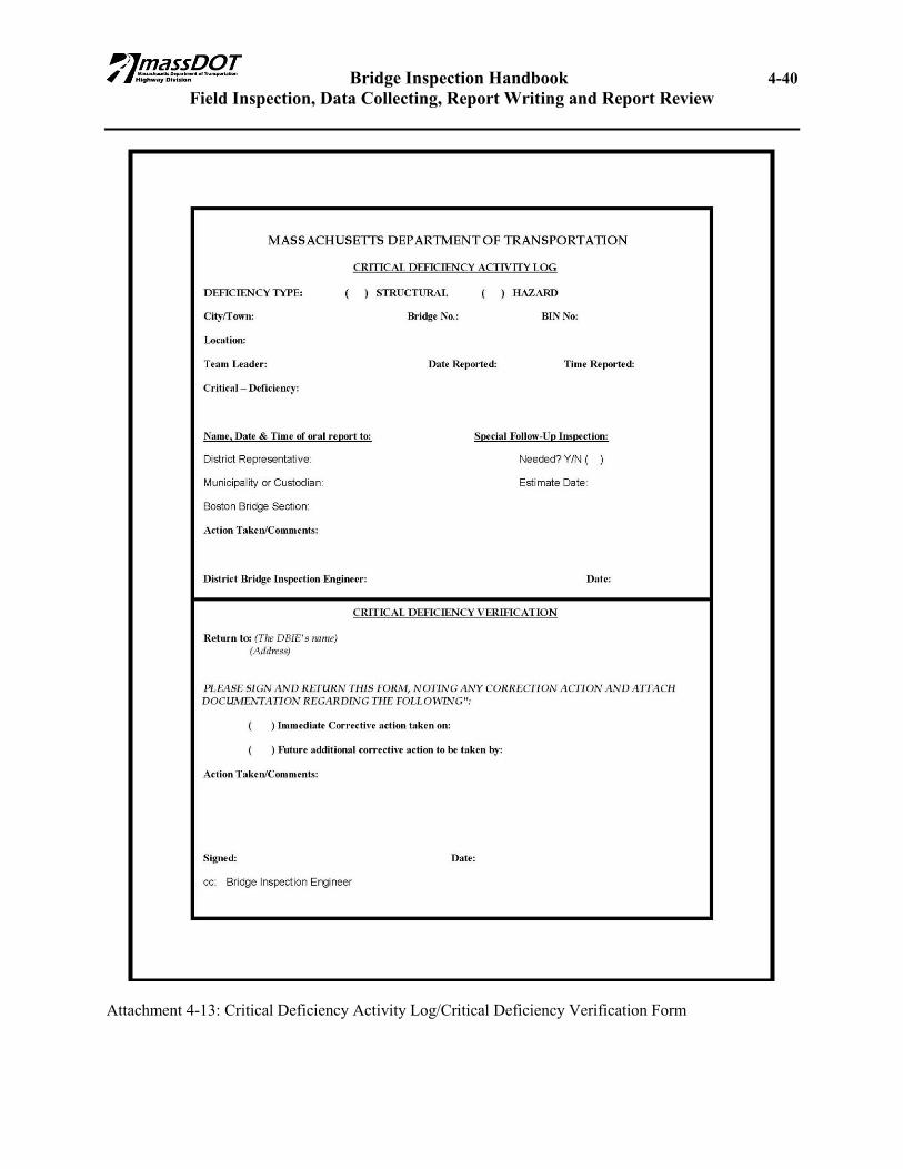
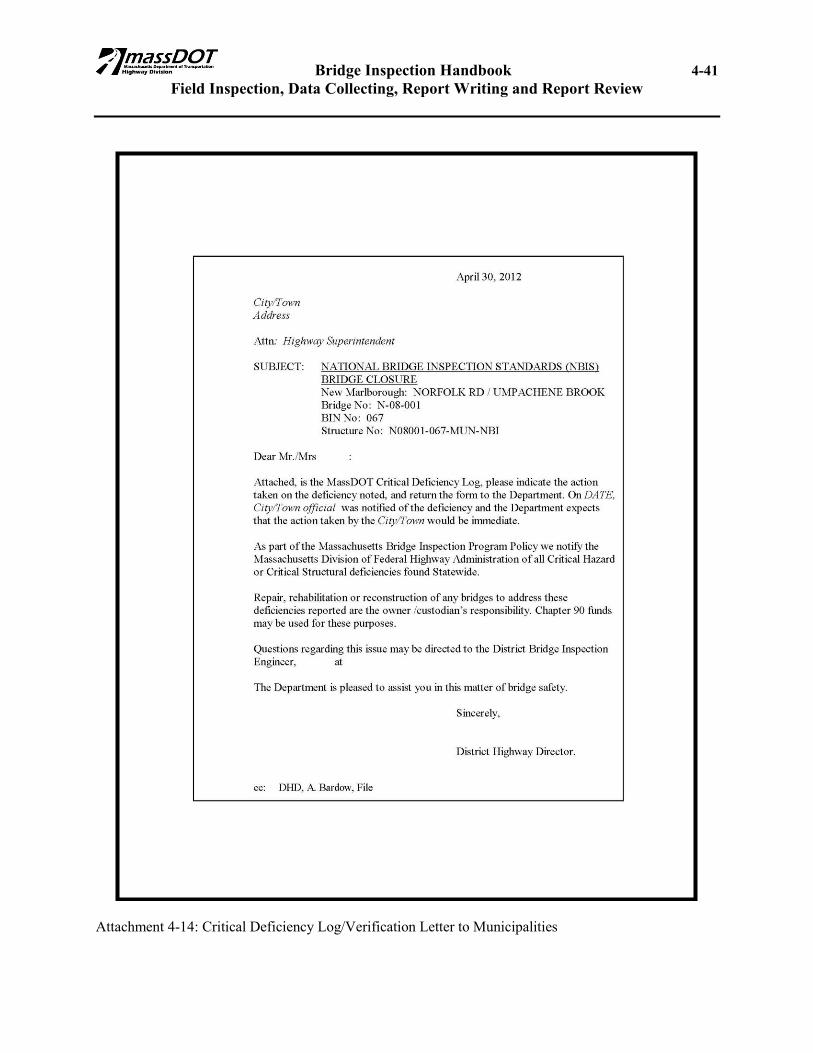
When completing an Element Level inspection report on a bridge that is a dive bridge, the Team Leader must ensure that the Underwater (U/W) Element Level inspection information is incorporated into the above water Element Level report. The U/W Element Level inspection data is a paper report only. The above water Element Level report is where the information is entered into the 4D database. The Team leader should obtain a copy of the latest U/W inspection report and Element Level inspection report prior to the above water inspection and incorporate the U/W information on his/her Element Level inspection report. 4.7 CS/I & CH/I PROCEDURE AND DOCUMENTATION In the case of Critical-Structural and Critical-Hazard Deficiencies which require Immediate corrective action, the Inspection Team Leader (TL) shall immediately verbally notify the District Bridge Inspection Engineer (DBIE), who after verification shall immediately verbally notify the District Bridge Engineer and the Area Engineer (who in return will immediately notify the Bridge Inspection Engineer, who in return will notify the State Bridge Engineer and FHWA officials). Upon observation of a deficiency, the Inspection Team Leader (TL) shall code all the deficiencies and complete the inspection report and include all sketches and photographs necessary to clearly identify the deficiencies. All reports shall then be given to the DBIE who after review of the report shall forward it to the District Bridge Engineer (DBE) for corrective action. The Team Leader shall indicate in the inspection report the notification of the DBIE. When the deficiency is verified and deemed to be a danger to pedestrians and/or vehicles, the site shall not be left unattended until the custodial owners have arrived and are preparing to respond with the necessary safety precautions. The Inspection Team shall document the safety precautions implemented in the Inspection Report. 4.7.1 CS/I & CH/I Field Observations at MassDOT Owned Bridges In the case of a Critical Deficiency, in addition to the prior paragraphs requirement, the DBIE shall prepare a Critical Deficiency Activity Log/Critical Deficiency Verification Form (See Attachment 4-13: Critical Deficiency Activity Log/Critical Deficiency Verification Form) and forward a scanned copy via email to the District Bridge Engineer. The log documents the reporting of the Critical Deficiency and requests that it be returned with documentation of the action taken. Copies shall be forwarded to the Bridge Inspection Engineer who in turn will forward a copy to the FHWA and shall catalog the CS Deficiency in a database. 4.7.2 CS/I & CH/I Field Observations at Municipally Owned Bridges In the case of Critical-Structural and Critical-Hazard Deficiencies which require Immediate corrective action, the District Bridge Inspection Engineer shall immediately notify the Municipal Officials in Charge. The DBIE shall prepare the Critical Deficiency Activity Log/Critical Deficiency Verification Form (see Attachment 4-13) with supporting documentation and send a copy to the Municipality with a cover letter signed by the District Highway Director (see Attachment 4-14). Copies shall be forwarded to the District
Bridge Inspection Handbook 4-18 Field Inspection, Data Collecting, Report Writing and Report Review
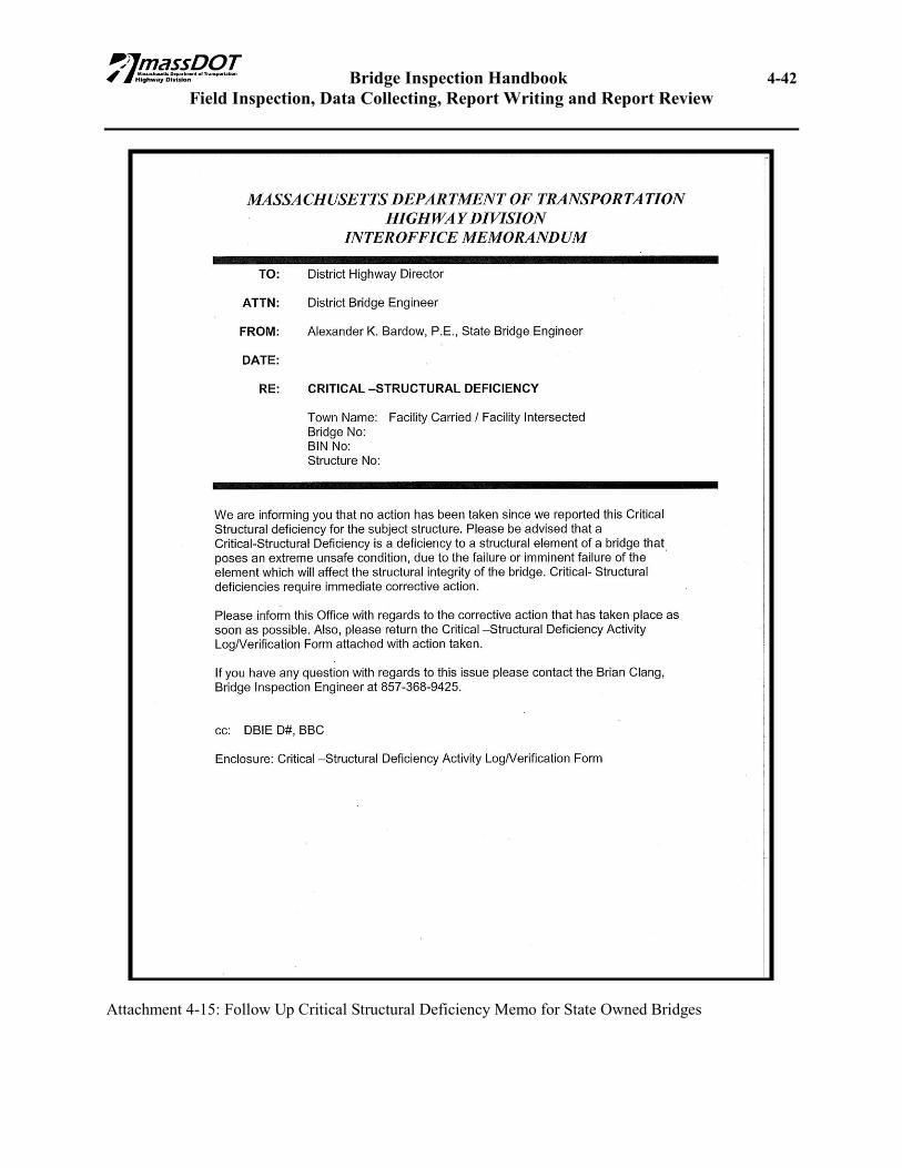
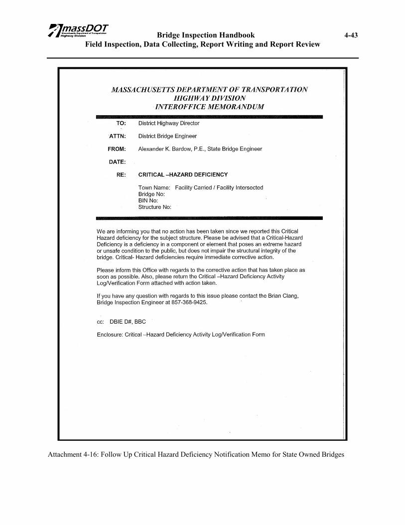
Bridge Engineer and Bridge Inspection Engineer who in turn will forward a copy to the FHWA and shall log the CS Deficiency in a log book. 4.7.3 Follow-Up Procedures on Critical Deficiency Findings The Follow-Up Critical Deficiency Inspection process is intended to meet the NBIS requirements for recording the corrective action taken by the Department or Municipality as a result of the Bridge Inspection Unit filing a Critical Deficiency in the Inspection Report found during an inspection. This procedure shall be used for all MassDOT and Municipally-owned bridges as follows. The process should be completed as soon as possible after repair, but no later than one month after the report of Critical Deficiency. 4.7.3.1 Procedures – Follow-Up Procedures for MassDOT Bridges The District Bridge Inspection Engineer shall verify and document the status of the Critical Deficiency. If the deficiency has been addressed then the DBIE shall ensure that the Verification Form has been signed and forwarded to the appropriate parties. Copies shall be forwarded to the Bridge Inspection Engineer who in turn will forward a copy to the FHWA and shall log the CS Deficiency in a log book. If the deficiency has not yet been addressed, the DBIE shall notify the ABIE that the status of the CS/I has not changed. The ABIE shall then forward the notification of the un-changed CS/I to the BIE who shall initiate a conversation with the District Bridge Engineer regarding the schedule for such repair. A hard copy of the email string should be retained as documentation of the situation. If the schedule for repairs has not been determined, then a follow up Critical Deficiency memo (Attachments 4-15 or 4-16) shall be sent. The completed Follow-Up Critical Deficiency Notification Form (See Attachment 4-15 and 4-16) and re-inspection report shall be filed in a separate file in both the District Bridge Inspection Engineer's Office and the Boston Bridge Inspection Engineer's Office. A copy of all correspondence will also be kept in both the District's and Boston's Bridge History File. 4.7.3.2 Procedures – Follow-Up Procedures for Municipally Owned Bridges The District Bridge Inspection Engineer shall verify and document the status of the Critical Deficiency. The DBIE shall then prepare the Follow-Up Critical Deficiency Notification Form (see Attachment 4-17 and 4-18) and send a copy to the Municipality with supporting documentation with cover letter signed by District Highway Director. Copies shall be forwarded to the Bridge Inspection Engineer who in turn will forward a copy to the FHWA and shall log the CS Deficiency in a log book. The completed Follow-Up Critical Deficiency Notification Form and re-inspection report shall be filed in a separate file in both the District Bridge Inspection Engineer's Office and the Boston Bridge Inspection Engineer's Office. A copy of all correspondence will also be kept in both the District's and Boston's Bridge History File. 4.7.3.3 Repeat Procedures – Follow-Up Procedures for MassDOT & Municipally Owned Bridges The procedures outlined in Section 4.7.3.1 and 4.7.3.2 shall be repeated when re-inspection verifies that the Critical Deficiency has not been corrected.
Bridge Inspection Handbook 4-19 Field Inspection, Data Collecting, Report Writing and Report Review
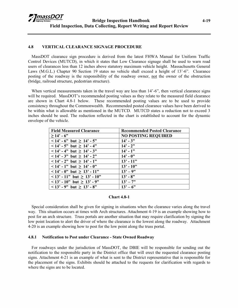
4.8 VERTICAL CLEARANCE SIGNAGE PROCEDURE MassDOT clearance sign procedure is derived from the latest FHWA Manual for Uniform Traffic Control Devices (MUTCD), in which it states that Low Clearance signage shall be used to warn road users of clearances less than 12 inches above statutory maximum vehicle height. Massachusetts General Laws (M.G.L.) Chapter 90 Section 19 states no vehicle shall exceed a height of 13’-6”. Clearance posting of the roadway is the responsibility of the roadway owner, not the owner of the obstruction (bridge, railroad structure, pedestrian structure). When vertical measurements taken in the travel way are less than 14’-6”, then vertical clearance signs will be required. MassDOT’s recommended posting values as they relate to the measured field clearance are shown in Chart 4.8-1 below. These recommended posting values are to be used to provide consistency throughout the Commonwealth. Recommended posted clearance values have been derived to be within what is allowable as mentioned in the MUTCD. MUTCD states a reduction not to exceed 3 inches should be used. The reduction reflected in the chart is established to account for the dynamic envelope of the vehicle.
Field Measured Clearance Recommended Posted Clearance ≥ 14’ - 6” NO POSTING REQUIRED < 14’ - 6” but ≥ 14’ - 5” 14’ - 3” < 14’ - 5” but ≥ 14’ - 4” 14’ - 2” < 14’ - 4” but ≥ 14’ - 3” 14’ - 1” < 14’ - 3” but ≥ 14’ - 2” 14’ - 0” < 14’ - 2” but ≥ 14’ - 1” 13’ - 11” < 14’ - 1” but ≥ 14’ - 0” 13’ - 10” < 14’ - 0” but ≥ 13’ - 11” 13’ – 9” < 13’ - 11” but ≥ 13’ - 10” 13’ - 8” < 13’ - 10” but ≥ 13’ - 9” 13’ – 7” < 13’ - 9” but ≥ 13’ - 8” 13’ – 6”
Chart 4.8-1
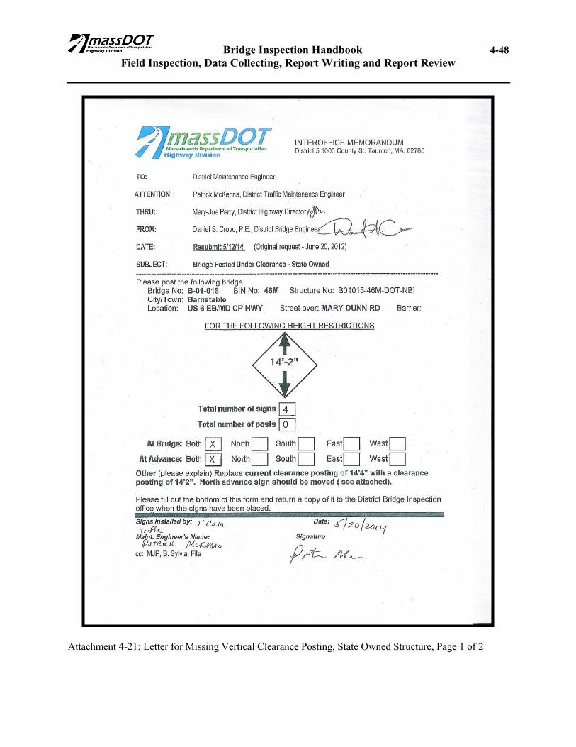
Special consideration shall be given for signing in situations when the clearance varies along the travel way. This situation occurs at times with Arch structures. Attachment 4-19 is an example showing how to post for an arch structure. Truss portals are another situation that may require clarification by signing the low point location to alert the driver of where the clearance is the lowest along the roadway. Attachment 4-20 is an example showing how to post for the low point along the truss portal. 4.8.1 Notification to Post under Clearance - State Owned Roadway For roadways under the jurisdiction of MassDOT, the DBIE will be responsible for sending out the notification to the responsible party in the District office that will erect the requested clearance posting signs. Attachment 4-21 is an example of what is sent to the District representative that is responsible for the placement of the signs. Exhibits should be attached to the requests for clarification with regards to where the signs are to be located.
Bridge Inspection Handbook 4-20 Field Inspection, Data Collecting, Report Writing and Report Review
4.8.2 Notification to Post under Clearance – Municipally Owned Roadway For roadways under the jurisdiction of a Municipality, the DBIE will be responsible for sending out the notification to the Municipality requesting that posted clearance signs are required. Attachment 4-22 is an example of what is to be sent to the Municipality. Exhibits should be attached to the requests for clarification with regards to where the signs are to be located. 4.9 COMPLETION and SUBMISSION of INSPECTION REPORTS by TEAM LEADERS All MassDOT Inspectors and Consultant Inspectors shall follow the procedures established for completing and submitting inspection reports as outlined in Sections 4.9.1 and 4.9.2, respectively. This procedure shall be used for all MassDOT and Municipally-owned bridges under the NBIS program. A complete inspection report includes a hard copy of the inspection report, Element Level inspection, and a marked up SI&A. Dive reports are not required to be submitted with the inspection report. They are sent to the bridge owner by the Underwater Operations Unit. 4.9.1 MassDOT Inspections Inspection reports completed by MassDOT teams shall be completed within the MassDOT Bridge Inspection Management System (4D) no later than the 15th day of the month following the inspection. 4.9.2 Consultant Inspections Inspection reports completed by Consultant teams shall be completed within 4D no later than 21 days following completion of the inspection, or in accordance with specific deadlines contained in their inspection contract. Upon initial completion of the inspection report and a QC/QA review by the Consultants PM, the Consultant TL should indicate within 4D that the report is ready for review. The Consultant TL should then send an email to the DBIE alerting him/her that the inspection report is ready for review. 4.10 DBIE INSPECTION REPORT REVIEW The DBIE and the ADBIE shall collectively review 100% of all inspection reports. The DBIE or ADBIE will sign all inspection reports reviewed by him/her. If the ADBIE signs the inspection report that they have reviewed, the ADBIE shall sign his/her name and place the word “for” after their name. The DBIE will be personally responsible for the review of all inspection reports that have an assigned numerical ratings of 5 or below for Item 58, Item 59, Item 60, or Item 62. The Assistant District Bridge Inspection Engineer may be responsible for the review of all inspection reports that have assigned numerical ratings of 6 or greater for Item 58, Item 59, Item 60, or Item 62 if the DBIE chooses to delegate that task to the ADBIE. When required based on operational needs, the DBIE may perform an inspection as the Team Leader. In such cases, the DBIE should sign the inspection report as the team leader. The ABIE will then perform the function of the DBIE and shall review and sign the inspection report. This occurrence shall only be done on an intermittent basis when extenuating circumstances arise.
Bridge Inspection Handbook 4-21 Field Inspection, Data Collecting, Report Writing and Report Review
Note: The signatory’s signature on the inspection report only signifies that the signatory has reviewed
the inspection report in accordance with FHWA and MassDOT standards. The signature does not under any circumstances signify, nor has it ever signified even prior to the formal issuance of this Handbook, the corroboration of the accuracy and thoroughness of either the field inspection itself, the assessment of the structure’s condition by the Team Leader, or the description of the structure’s condition by the Team Leader on the inspection report.
4.10.1 DBIE Review of MassDOT Inspections The DBIE shall complete a review of all internally completed inspection reports in a timely manner and in conformance with metrics determined by the District. Approved reports shall be signed and one copy shall be submitted to the Bridge Inspection Engineer. 4.10.2 DBIE Review of Consultant Inspections The DBIE will complete an expeditious review of the inspection report within 4D in a timely manner and in conformance with metrics determined by the District. If revisions are requested, the DBIE should either email the Consultant’s PM and TL with the requested changes, or indicate within 4D the requested changes. When changes are made, the Consultant PM and TL should again inform the DBIE. When the report is deemed acceptable the DBIE shall check the report approved within 4D. The consultant shall print out a hard copy, sign the original and submit it with two copies to the Bridge Inspection Engineer. The BIE will then update 4D with the report submission information. The report will be forwarded to the DBIE through the ABIE with a Bridge Inspection Consultant Performance Evaluation Report form, see Attachment 4-23. The DBIE is to provide an evaluation score, sign the inspection report and copies and return one report to the ABIE along with the evaluation form. 4.10.3 DBIE Review of Inspection Report Content A review by the DBIE will include the review of all inspection reports for bridges in their district prepared by MassDOT staff and/or Consultants for compliance with FHWA, NBIS and MassDOT requirements before the data is entered in the bridge inventory files. The DBIE is not responsible for reviewing inspection reports for bridges of other state agencies. The DBIE’s review will consist of the following:
1. Overall review of the Inspection Report to ensure that the correct form has been used, that the correct bridge is identified and that all required information has been entered.
2. Review that all information has been correctly entered in accordance with the FHWA Coding
Guide and the MassDOT Bridge Inspection Handbook criteria. This review will include but not be limited to a check that proper coding conventions, format, significant digits and correct units have been used.

Bridge Inspection Handbook 4-22 Field Inspection, Data Collecting, Report Writing and Report Review
3. Check that the Condition Ratings for Items 58 through 62 are consistent with the condition ratings of the individual sub-items.
4. Check that there is adequate documentation for inspection sub-items with condition ratings of 6
or lower.
5. Check that all Photographs and/or Sketches have been properly cross referenced to the Inspection Report.
6. Check that there is consistency of information between the current Inspection Report and
previous Inspection Reports, as well as the Dive Report and/or Rating Report, if applicable.
7. Check that proper documentation was incorporated into the inspection report for any changes that may have occurred from the previous SI&A and previous Inspection Report.
8. Review of all Items in the SI&A after data entry to check that they have been properly and
correctly entered.
9. For Initial Inventory Inspections, a check of the inventory data on the SI&A against the construction plans to ensure that the data is consistent.
10. For every initial inspection, a set of Inventory Photos has been taken and included in the report.
11. For every routine inspection, an Element Level inspection created with the routine inspection
shall be reviewed for accuracy, including elements, quantities and condition states.
4.11 DISTRIBUTION OF COMPLETED INSPECTION REPORTS Upon approval of the inspection report, the DBIE shall review the marked up SI&A and ensure all changes are made. The DBIE shall print out a new SI&A and attach it to the inspection report. Completed Inspection reports shall be distributed by the DBIE to the bridge owners as follows:
Boston HQ copy: Report; SIA; Marked-up SIA; Element Level Inspection Report
District copy: Report, Element Level Inspection Report
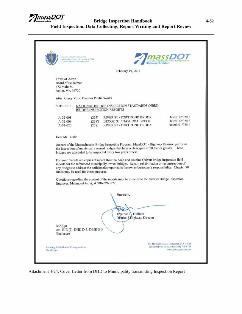
Municipal copy: Report only. The cover letter* is from the district with a copy to the Bridge Inspection Engineer. See attachment 4-24.
* Cover letter attachments shown being signed by the DHD are intended to have the minimum language required, the District have the right to add additional language as they see fit.
Bridge Inspection Handbook 4-23 Field Inspection, Data Collecting, Report Writing and Report Review
4.12 ABIE REVIEW OF COMPLETED INSPECTION REPORTS Upon receiving the reviewed inspection reports from the DBIE, the ABIE shall review 100% of the inspection reports with numerical condition ratings of 4 or less on Items 58, 59, 60, or 62. Also the ABIE shall review a minimum of 10% of all reports for completeness. Upon completion of the review by the ABIE, he/she will check off in 4D whether the review was a regular review or an in depth review. Upon completion of the ABIE’s review, the ABIE shall place the accepted inspection report into the Boston Bridge history file. If an inspection report is rejected by the ABIE, the ABIE shall return the inspection report to the DBIE with comments, so that they may forward the rejected inspection report to the Team Leader for revision. When the rejection comments have been addressed, the Team Leader will then resubmit the inspection report to the DBIE for review, who will concur and accept the inspection report in 4D and then resubmit the report to the ABIE.

Bridge Inspection Handbook 4-24 Field Inspection, Data Collecting, Report Writing and Report Review
4.13 CHAPTER 4 ATTACHMENTS
Attachment 4-1: Quick Reference Guide for the Element Level Condition States, Page 1 of 5

Bridge Inspection Handbook 4-25 Field Inspection, Data Collecting, Report Writing and Report Review
Attachment 4-1: Quick Reference Guide for the Element Level Condition States, Page 2 of 5

Bridge Inspection Handbook 4-26 Field Inspection, Data Collecting, Report Writing and Report Review
Attachment 4-1: Quick Reference Guide for the Element Level Condition States, Page 3 of 5

Bridge Inspection Handbook 4-27 Field Inspection, Data Collecting, Report Writing and Report Review
Attachment 4-1: Quick Reference Guide for the Element Level Condition States, Page 4 of 5

Bridge Inspection Handbook 4-28 Field Inspection, Data Collecting, Report Writing and Report Review
Attachment 4-1: Quick Reference Guide for the Element Level Condition States, Page 5 of 5

Bridge Inspection Handbook 4-29 Field Inspection, Data Collecting, Report Writing and Report Review
Attachment 4-2: Bridge Scour – Item 113 Re-evaluation Form

Bridge Inspection Handbook 4-30 Field Inspection, Data Collecting, Report Writing and Report Review
Attachment 4-3: Vertical Clearance Location Placed on a Framing Plan

Bridge Inspection Handbook 4-31 Field Inspection, Data Collecting, Report Writing and Report Review
Attachment 4-4: Average Daily Traffic Count Formulas & Example Calculations

Bridge Inspection Handbook 4-32 Field Inspection, Data Collecting, Report Writing and Report Review
Attachment 4-5: Typical Underside of Deck Condition Sketch

Bridge Inspection Handbook 4-33 Field Inspection, Data Collecting, Report Writing and Report Review
Attachment 4-6: Typical Beam End Elevation Sketch

Bridge Inspection Handbook 4-34 Field Inspection, Data Collecting, Report Writing and Report Review
Attachment 4-7 Typical Beam Elevation Sketch
Bridge Inspection Handbook 4-35 Field Inspection, Data Collecting, Report Writing and Report Review
Attachment 4-8: Typical Cross Section View of Deteriorated Prestressed Concrete Beam
Bridge Inspection Handbook 4-36 Field Inspection, Data Collecting, Report Writing and Report Review
Attachment 4-9: Example 1: Condition Coding of Item 60
Bridge Inspection Handbook 4-37 Field Inspection, Data Collecting, Report Writing and Report Review
Attachment 4-10: Example 2: Condition Coding of Item 60

Bridge Inspection Handbook 4-38 Field Inspection, Data Collecting, Report Writing and Report Review
Attachment 4-11: Example of presenting information in an Inspection Report

Bridge Inspection Handbook 4-39 Field Inspection, Data Collecting, Report Writing and Report Review
Attachment 4-12: Marked up copy of SI&A sheet
Bridge Inspection Handbook 4-40 Field Inspection, Data Collecting, Report Writing and Report Review
Attachment 4-13: Critical Deficiency Activity Log/Critical Deficiency Verification Form
Bridge Inspection Handbook 4-41 Field Inspection, Data Collecting, Report Writing and Report Review
Attachment 4-14: Critical Deficiency Log/Verification Letter to Municipalities
Bridge Inspection Handbook 4-42 Field Inspection, Data Collecting, Report Writing and Report Review
Attachment 4-15: Follow Up Critical Structural Deficiency Memo for State Owned Bridges
Bridge Inspection Handbook 4-43 Field Inspection, Data Collecting, Report Writing and Report Review
Attachment 4-16: Follow Up Critical Hazard Deficiency Notification Memo for State Owned Bridges

Bridge Inspection Handbook 4-44 Field Inspection, Data Collecting, Report Writing and Report Review
Attachment 4-17: Follow Up Critical Structural Deficiency Notification Letter to City/Town

Bridge Inspection Handbook 4-45 Field Inspection, Data Collecting, Report Writing and Report Review
Attachment 4-18: Follow Up Critical Hazard Deficiency Notification Letter to City/Town

Bridge Inspection Handbook 4-46 Field Inspection, Data Collecting, Report Writing and Report Review
Attachment 4-19: Example of Vertical Clearance Posting for Rigid Frame Structure

Bridge Inspection Handbook 4-47 Field Inspection, Data Collecting, Report Writing and Report Review
Attachment 4-20: Example of Vertical Clearance Posting for Truss Portal Structure
Bridge Inspection Handbook 4-48 Field Inspection, Data Collecting, Report Writing and Report Review
Attachment 4-21: Letter for Missing Vertical Clearance Posting, State Owned Structure, Page 1 of 2

Bridge Inspection Handbook 4-49 Field Inspection, Data Collecting, Report Writing and Report Review
Attachment 4-21: Letter for Missing Vertical Clearance Posting, State Owned Structure, Page 2 of 2

Bridge Inspection Handbook 4-50 Field Inspection, Data Collecting, Report Writing and Report Review
Attachment 4-22: Letter for Missing Vertical Clearance Posting, Municipally Owned Structure

Bridge Inspection Handbook 4-51 Field Inspection, Data Collecting, Report Writing and Report Review
Attachment 4-23: Bridge Inspection Consultant Performance Evaluation Report
Bridge Inspection Handbook 4-52 Field Inspection, Data Collecting, Report Writing and Report Review
Attachment 4-24: Cover Letter from DHD to Municipality transmitting Inspection Report