chapter 4 dynamics: newton’s laws of...
TRANSCRIPT
Chapter 4
Dynamics: Newton’s Laws of Motion

• Force
• Newton’s First Law of Motion
• Mass
• Newton’s Second Law of Motion
• Newton’s Third Law of Motion
• Weight – the Force of Gravity; and the Normal Force
• Applications Involving Friction, Inclines
AssignmentAssignment 44
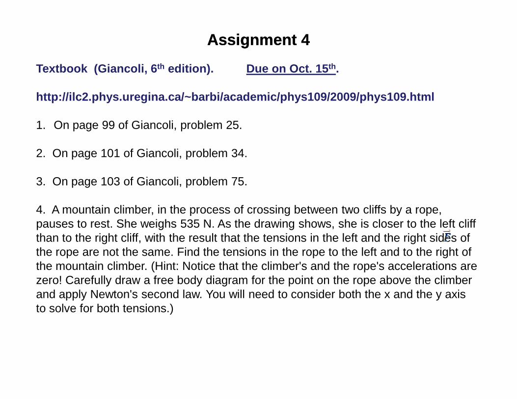
Textbook (Giancoli, 6 th edition). Due on Oct. 15 th.
http://ilc2.phys.uregina.ca/~barbi/academic/phys109 /2009/phys109.html
1. On page 99 of Giancoli, problem 25.
2. On page 101 of Giancoli, problem 34.
3. On page 103 of Giancoli, problem 75.
4. A mountain climber, in the process of crossing between two cliffs by a rope, pauses to rest. She weighs 535 N. As the drawing shows, she is closer to the left cliff than to the right cliff, with the result that the tensions in the left and the right sides of the rope are not the same. Find the tensions in the rope to the left and to the right of the mountain climber. (Hint: Notice that the climber's and the rope's accelerations arezero! Carefully draw a free body diagram for the point on the rope above the climberand apply Newton's second law. You will need to consider both the x and the y axisto solve for both tensions.)
Recalling Recalling LastLast LectureLectureRecalling Recalling LastLast LectureLecture
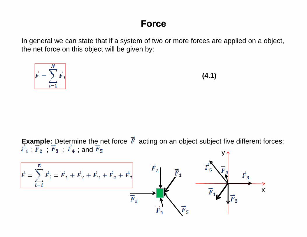
ForceForce
In general we can state that if a system of two or more forces are applied on a object,the net force on this object will be given by:
(4.1)
Example: Determine the net force acting on an object subject five different forces:; ; ; ; and
x
y
Newton’s Laws of MotionNewton’s Laws of Motion
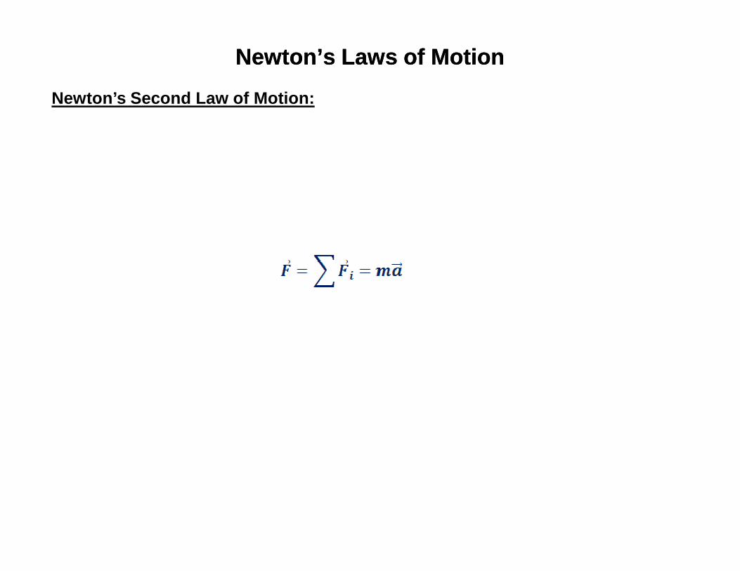
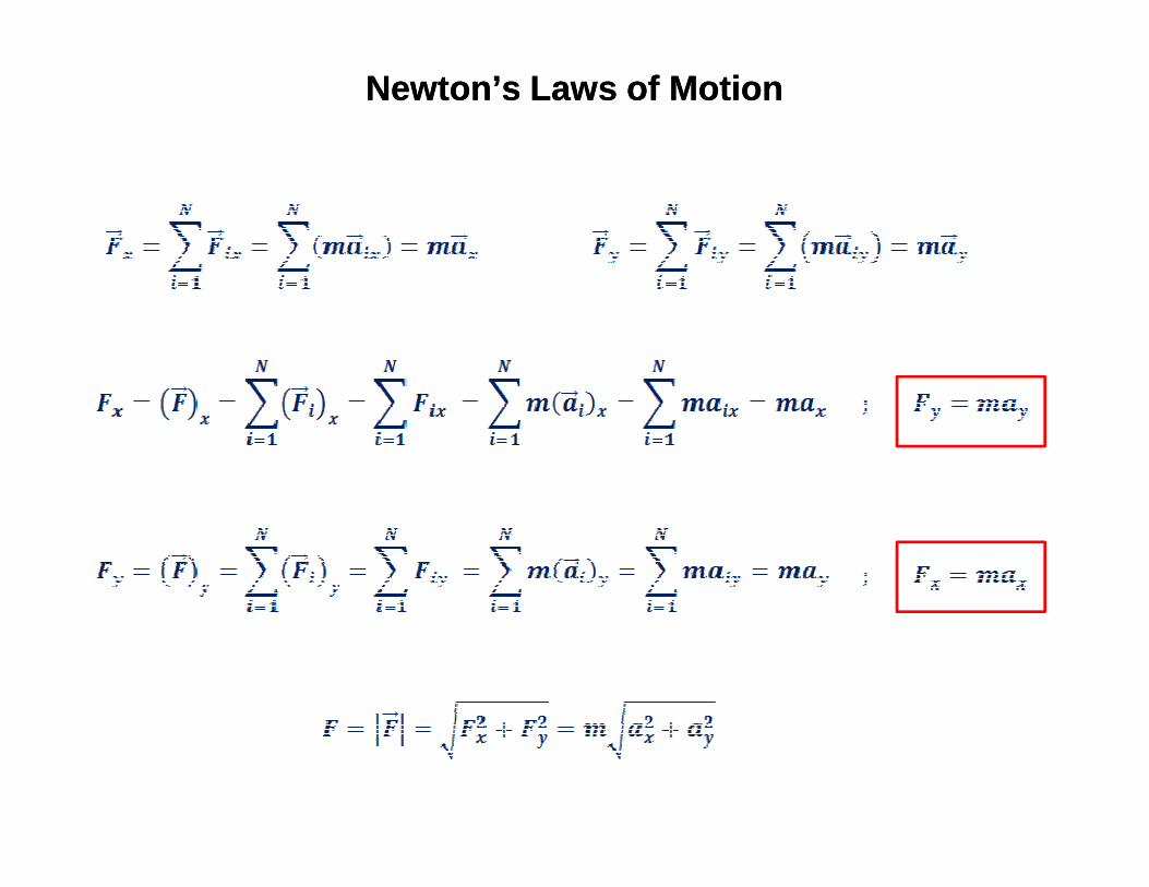
Newton’s Second Law of Motion:
Newton’s Laws of MotionNewton’s Laws of Motion

Newton’s Laws of MotionNewton’s Laws of Motion
Newton’s Third Law of Motion:
The Newton’s third law can be mathematically represented as:
Where
(4.3)
Where
is the force applied by A on B
and
is the force resulting of the reaction of by B on A
Weight Weight –– the Force of Gravity and the Normal Forcethe Force of Gravity and the Normal Force
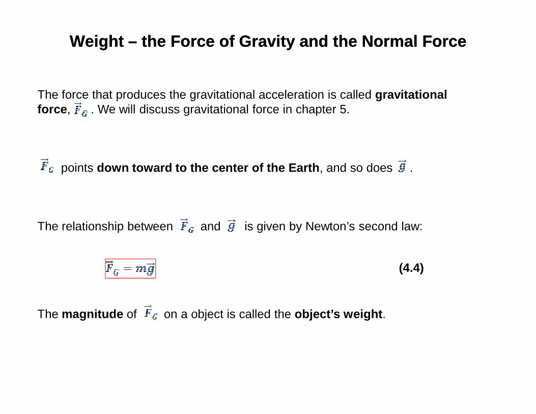
The force that produces the gravitational acceleration is called gravitational force , . We will discuss gravitational force in chapter 5.
points down toward to the center of the Earth , and so does .
The relationship between and is given by Newton’s second law:
The magnitude of on a object is called the object’s weight .
(4.4)
Weight Weight –– the Force of Gravity and the Normal Forcethe Force of Gravity and the Normal Force
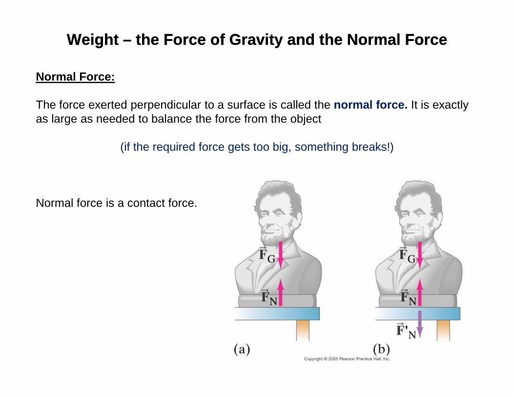
Normal Force:
The force exerted perpendicular to a surface is called the normal force. It is exactly as large as needed to balance the force from the object
(if the required force gets too big, something breaks!)
Normal force is a contact force.Normal force is a contact force.
Newton’s Laws of MotionNewton’s Laws of Motion
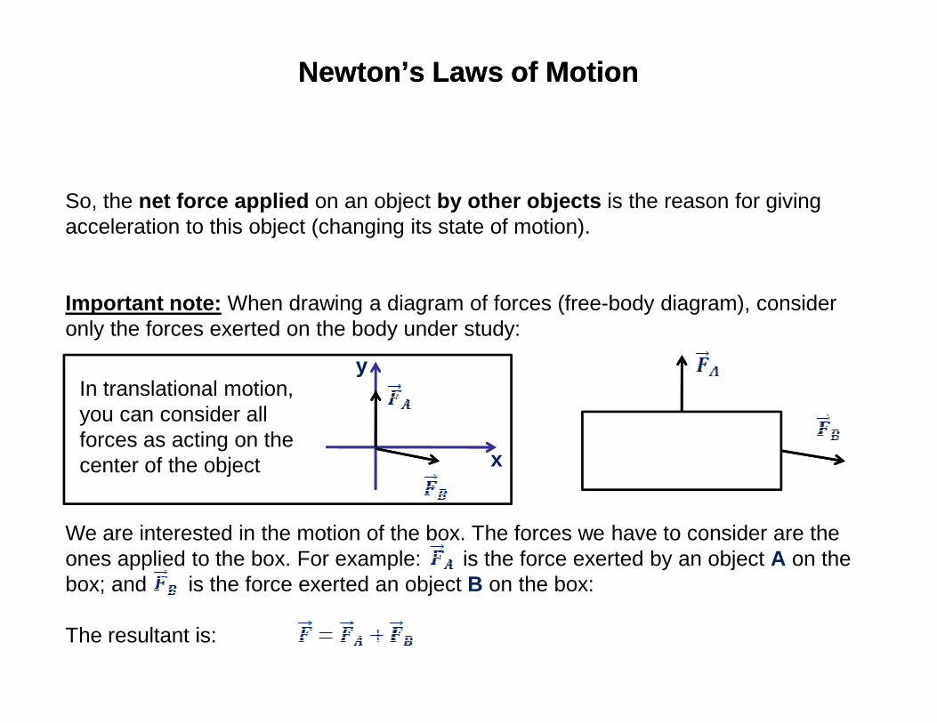
So, the net force applied on an object by other objects is the reason for giving acceleration to this object (changing its state of motion).
Important note: When drawing a diagram of forces (free-body diagram), consider only the forces exerted on the body under study:
y
We are interested in the motion of the box. The forces we have to consider are the ones applied to the box. For example: is the force exerted by an object A on the box; and is the force exerted an object B on the box:
The resultant is:
y
x
In translational motion, you can consider all forces as acting on the center of the object
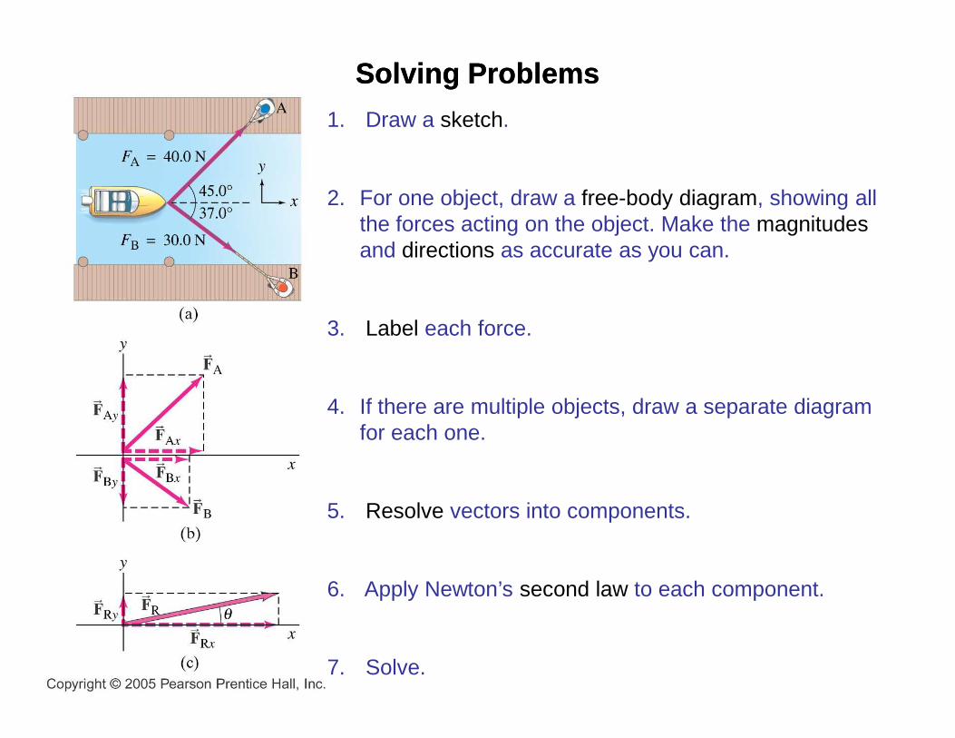
1. Draw a sketch.
2. For one object, draw a free-body diagram, showing all the forces acting on the object. Make the magnitudesand directions as accurate as you can.
3. Label each force.
SolvingSolving ProblemsProblems
4. If there are multiple objects, draw a separate diagram for each one.
5. Resolve vectors into components.
6. Apply Newton’s second law to each component.
7. Solve.
Newton’s Laws of MotionNewton’s Laws of Motion
Newton’s Second Law of Motion:
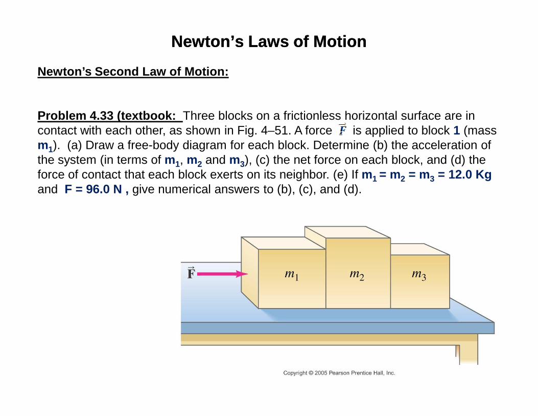
Problem 4.33 (textbook: Three blocks on a frictionless horizontal surface are in contact with each other, as shown in Fig. 4–51. A force is applied to block 1 (mass m1). (a) Draw a free-body diagram for each block. Determine (b) the acceleration of the system (in terms of m1, m2 and m3), (c) the net force on each block, and (d) the force of contact that each block exerts on its neighbor. (e) If m1 = m2 = m3 = 12.0 Kg and F = 96.0 N , give numerical answers to (b), (c), and (d).

Problem 4.33 (textbook) :
a) In the free-body diagrams below,
= force on block 1 exerted by block 2,
= force on block 2 exerted by block 1,
= force on block 2 exerted by block 3, and
= force on block 3 exerted by block 2.
1 2Fr
2 1Fr
2 3Fr
3 2Fr
= force on block 3 exerted by block 2.
By Newton’s 3rd law:
The magnitudes of and are equal and they point in opposite directions. The magnitudes of and are equal and they point in opposite directions.
3 2F
21Fr
12Fr
23Fr
32Fr
1m gr
N1Fr
Fr
1 2Fr
2m gr
N2Fr
2 1Fr
2 3Fr
3m gr
N3Fr
3 2Fr
Problem 4.33 (textbook) :
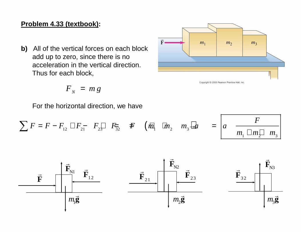
b) All of the vertical forces on each block add up to zero, since there is no acceleration in the vertical direction. Thus for each block,
For the horizontal direction, we have
NF m g=
F
1m gr
N1Fr
Fr
1 2Fr
2m gr
N2Fr
2 1Fr
2 3Fr
3m gr
N3Fr
3 2Fr
( )12 21 23 32 1 2 3
1 2 3
F
F F F F F F F m m m a am m m
= − + − + = = + + → =+ +∑

Problem 4.33 (textbook) :
c) For each block, the net force must be F = ma by Newton’s 2nd law. Each block has the same acceleration since they are in contact with each other.
11
1 2 3
net
m FF
m m m=
+ +
2m FF = 2
2
1 2 3
net
m FF
m m m=
+ +
33
1 2 3
net
m FF
m m m=
+ +
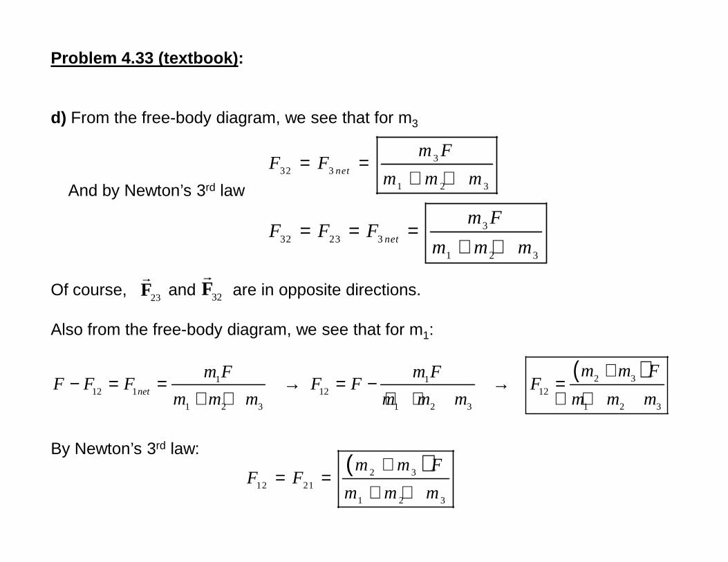
Problem 4.33 (textbook) :
d) From the free-body diagram, we see that for m3
And by Newton’s 3rd law
Of course, and are in opposite directions.
332 3
1 2 3
net
m FF F
m m m= =
+ +
332 23 3
1 2 3
net
m FF F F
m m m= = =
+ +
Fr
Fr
Of course, and are in opposite directions.
Also from the free-body diagram, we see that for m1:
By Newton’s 3rd law:
23Fr
32Fr
( )2 31 112 1 12 12
1 2 3 1 2 3 1 2 3
net
m m Fm F m FF F F F F F
m m m m m m m m m
+− = = → = − → =
+ + + + + +
( )2 312 21
1 2 3
m m FF F
m m m
+= =
+ +
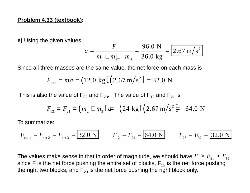
Problem 4.33 (textbook) :
e) Using the given values:
Since all three masses are the same value, the net force on each mass is
This is also the value of F32 and F23. The value of F12 and F21 is
2
1 2 3
96.0 N2.67 m s
36.0 kg
Fa
m m m= = =
+ +
( ) ( )212.0 kg 2.67 m s 32.0 NnetF ma= = =
This is also the value of F32 and F23. The value of F12 and F21 is
To summarize:
The values make sense in that in order of magnitude, we should have , since F is the net force pushing the entire set of blocks, F12 is the net force pushing the right two blocks, and F23 is the net force pushing the right block only.
( ) ( )( )2
12 21 2 3 24 kg 2.67 m s 64.0 NF F m m a= = + = =
net 1 net 2 net 3 12 21 23 3232.0 N 64.0 N 32.0 NF F F F F F F= = = = = = =
21 32F F F> >
Solving problemsSolving problems
The examples in the textbook are good source of information on how to solve problems using diagrams of forces and using the methods of components for vector addition.
Please, study them !!!!!!!!!!!!!
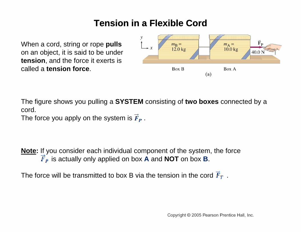
When a cord, string or rope pullson an object, it is said to be undertension , and the force it exerts is called a tension force .
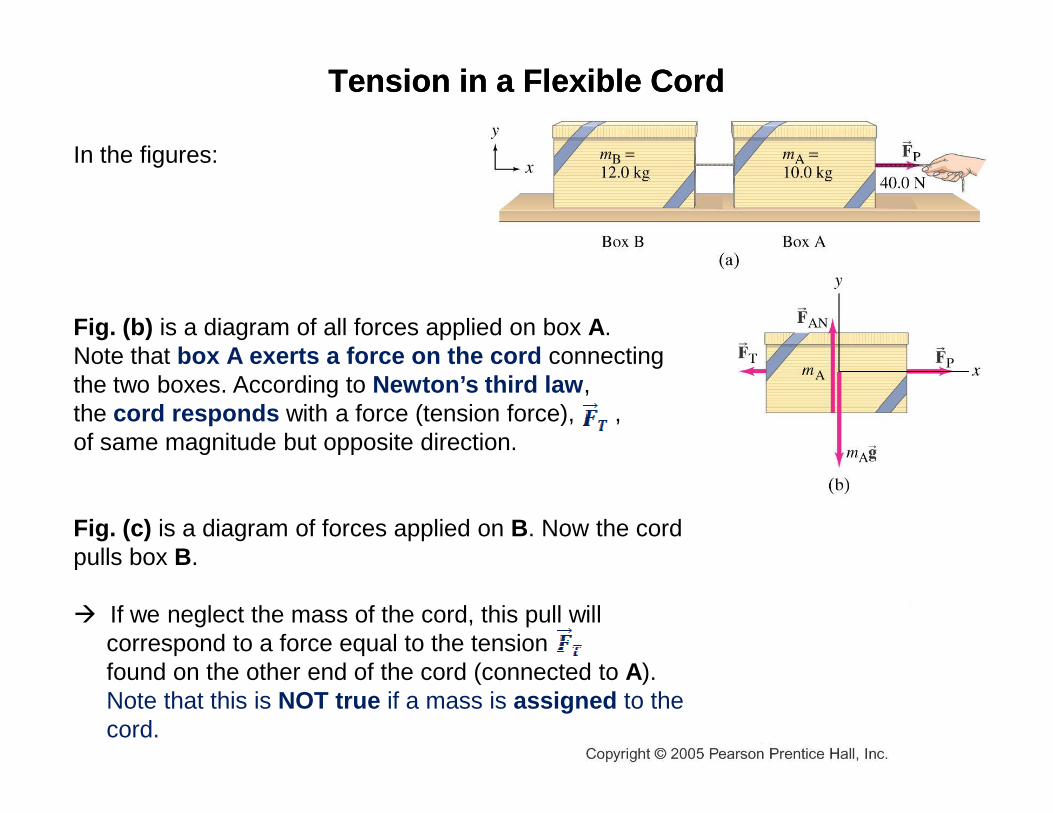
The figure shows you pulling a SYSTEM consisting of two boxes connected by a cord. The force you apply on the system is .
Tension in a Flexible CordTension in a Flexible Cord
The force you apply on the system is .
Note: If you consider each individual component of the system, the force is actually only applied on box A and NOT on box B.
The force will be transmitted to box B via the tension in the cord .
Tension in a Flexible CordTension in a Flexible Cord
In the figures:
Fig. (b) is a diagram of all forces applied on box A.Note that box A exerts a force on the cord connecting the two boxes. According to Newton’s third law , the cord responds with a force (tension force), , the cord responds with a force (tension force), , of same magnitude but opposite direction.
Fig. (c) is a diagram of forces applied on B. Now the cordpulls box B.
� If we neglect the mass of the cord, this pull will correspond to a force equal to the tension found on the other end of the cord (connected to A). Note that this is NOT true if a mass is assigned to the cord.
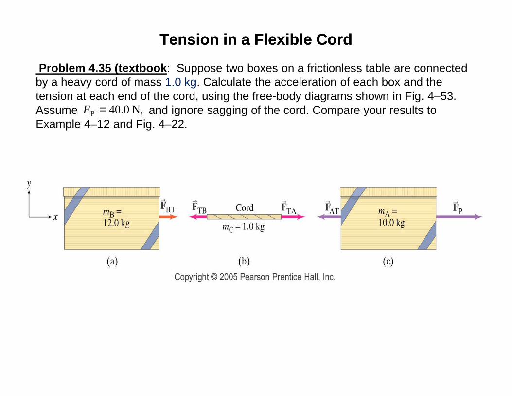
Problem 4.35 (textbook : Suppose two boxes on a frictionless table are connected by a heavy cord of mass 1.0 kg. Calculate the acceleration of each box and the tension at each end of the cord, using the free-body diagrams shown in Fig. 4–53. Assume and ignore sagging of the cord. Compare your results to Example 4–12 and Fig. 4–22.
Tension in a Flexible CordTension in a Flexible Cord
N, 0.40P =F

Problem 4.35 (textbook) :
Initially, treat the two boxes and the rope as a single system. (But note that the rope hasa mass, so the tension is not the same throughout the rope)
� The only accelerating force on the system is . The mass of the system is 23.0 kg, and so using Newton’s 2nd law, the acceleration of the system is
PFr
2P 40.0 N1.74 m s
23.0 kg
Fa
m= = =
This is the acceleration of each piece of the system.
� Now consider the left box alone. The only force on it is , and it has the acceleration found above. Thus can be found from Newton’s 2nd law.
� Now consider the rope alone. The net force on it is , and it also has the acceleration found above. Thus can be found from Newton’s 2nd law.
23.0 kgm
B TFr
TAF
( )( )2
BT B 12.0 kg 1.74 m s 20.9 NF m a= = =
TA TB−F Fr r
( )( )2
TA TB TA TB C 20.9 N 1.0 kg 1.74 m s 22.6 NCF F m a F F m a− = → = + = + =
B TFr
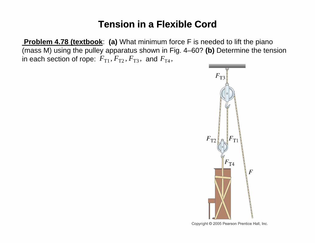
Problem 4.78 (textbook : (a) What minimum force F is needed to lift the piano (mass M) using the pulley apparatus shown in Fig. 4–60? (b) Determine the tension in each section of rope: and
Tension in a Flexible CordTension in a Flexible Cord
, , , T3T2T1 FFF ,T4F

Problem 4.78 (textbook) :
(a) To find the minimum force, assume that the piano is moving with a constant velocity. Since the piano is not accelerating,
For the lower pulley, since the tension in a rope is the same throughout, and since the pulley is not accelerating, it is seen that
T 4F Mg=
T1 T 2 T1 T1 T 22 2F F F Mg F F Mg+ = = → = =
Also, since , then
(b)Draw a free-body diagram for the upper pulley. From that diagram, we see that
T 2F F=
2F Mg=
T 3 T1 T 2
3
2
MgF F F F= + + =
T1 T 2 T 3 T 42 3 2 F F M g F M g F M g= = = =
Lower
Pulley
Upper
Pulley
Fr
T1Fr
T1Fr
T2Fr
T2Fr
T3Fr
T4Fr