chapter 4 deformation and strain. deformation describes the complete transformation from the initial...
TRANSCRIPT

CHAPTER 4
DEFORMATION AND STRAIN
DEFORMATION AND STRAIN
• Deformation describes the complete transformation from the initial to the final geometry (shape, position and orientation) of a body.
• Strain describes the changes of points in a body relative to each other (distortion of a body shape). It is only a component of deformation.
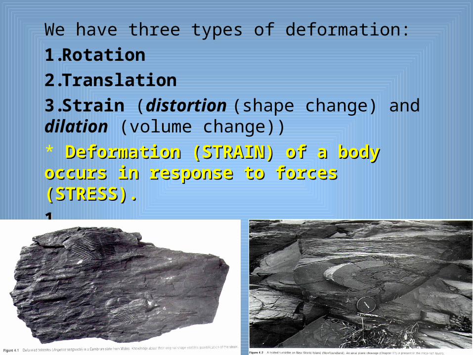
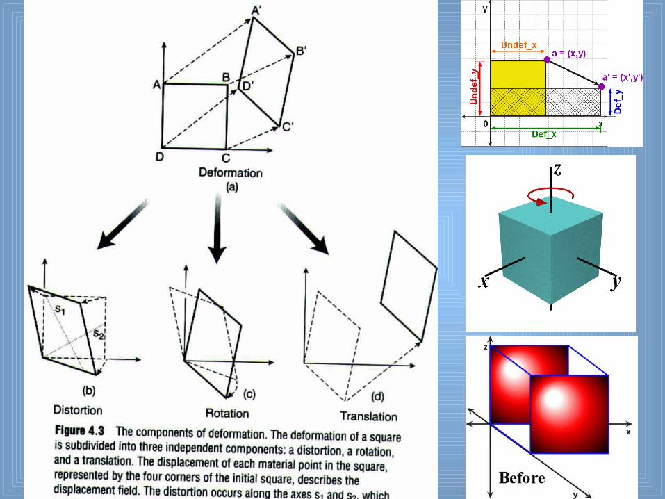
We have three types of deformation:
1.Rotation
2.Translation
3.Strain (distortion (shape change) and dilation (volume change))
* Deformation (STRAIN) of a body occurs in Deformation (STRAIN) of a body occurs in response to forces (STRESS).response to forces (STRESS).
1.1.

• In practice, it is very difficult to determine the translation, rotation and dilation, because it is impossible to determine the original position of a body. But more common we know the original shape of a body, so we can quantify strain.
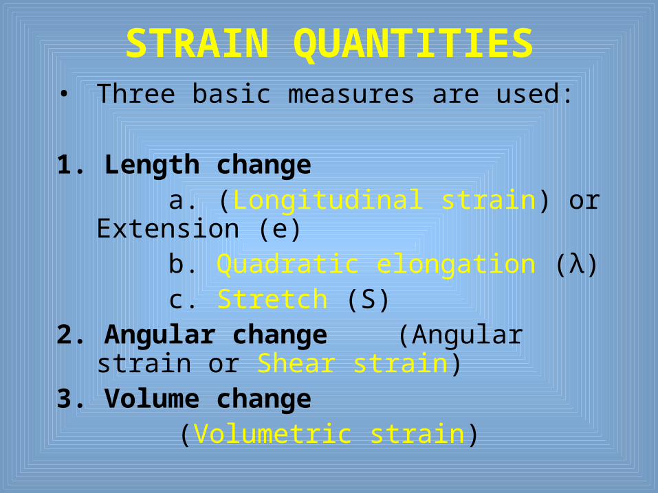
STRAIN QUANTITIES• Three basic measures are used:
1. Length change a. (Longitudinal strain) or Extension (e) b. Quadratic elongation (λ) c. Stretch (S)2. Angular change (Angular
strain or Shear strain)3. Volume change
(Volumetric strain)

Longitudinal Strain (e) e = ∆l/l ° = (l-l °)/l °
• e=(l/l °)-1, (l/l °)=1+e• (Exa. l° = 1 m, l =1.33 m)• e = 0.33 means 33% extension (elongation)• While e = -0.33 means –33% shorteningAlso for the three principal axes (X, Y & Z) of strain we used e1, e2, e3 for the largest, intermediate and shortest principal strain axesrespectively e1 e2 e3

b. Quadratic elongation (λ)
(λ)=(l/lo)²= (1+e)² c. Stretch (S)
S=(λ)1/2 =(l/lo) = (1+e)
Length change

Angular Strain• Angular strains are slightly more difficult and are
measured by the change in angle between two lines that were initially perpendicular.
• The change in angle is the angular shear (Psi), more commonly its tangent is used; shear strain ().
= tan
Volumetric Strain
• Similar equation of length changes can be given for 3 dimensional (volume) change
• volumetric strain = v-v°/v° = δv/v°
• When we have +ve%, means increase in Volume
• When we have –ve%, means decrease in Volume
STRAIN is dimensionless quantity

HOMOGENOUS STRAIN • When any two portions of the body that were
similar in form and orientation before the strain are still similar in form and orientation after the strain, we call them homogenous strain.
• To have homogenous strain 4 geometric components should be occur:-
1. Originally straight lines remain straight
2. Originally parallel lines remain parallel
* Circles become ellipses
* 3D spheres become ellipsoids.

• If any one of these features does not apply, we call the strain heterogeneous.
• HETEROGENEOUS STRAINis more common andmore complex to describe. Therefore, wecommonly separating itinto homogeneous Strain bodies to analyze.

STRAIN ELLIPSOID• Also the length of those lines changed.• In three dimensions, we need 3 material lines
that remain perpendicular after strain to define the axes of strain ellipsoid.
• The material lines that are perpendicular before and after strain are called the principal strain axes, which their lengths after deformation define the strain magnitude.
• We use X Y Z for
the principal strain axes

• For any deformed body, four material lines (reference lines) should be determined.
• Two material lines remain perpendicular before and after strain, and they known as the principal axes of strain ellipse.
STRAIN ELLIPSE

Incremental Stress Routes
• Different routes to the same final state (Finite strain).

Coaxial Strain
• If the same material lines remain the principal strain axes throughout each increment, then it is coaxial, non-rotational strain accumulation
• Principal axes of strain ellipsoid do not rotate through material, therefore the deformation is "coaxial“ and “nonrotational”.
• This is called Pure Shear.
Noncoaxial Strain
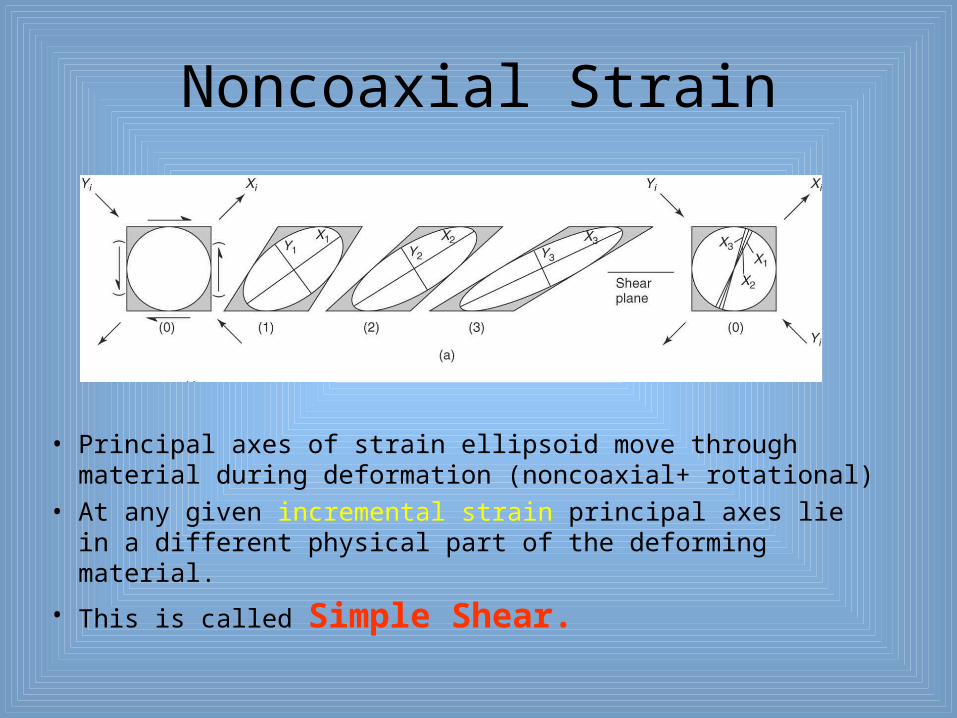
• Principal axes of strain ellipsoid move through material during deformation (noncoaxial+ rotational)
• At any given incremental strain principal axes lie in a different physical part of the deforming material.
• This is called Simple Shear.
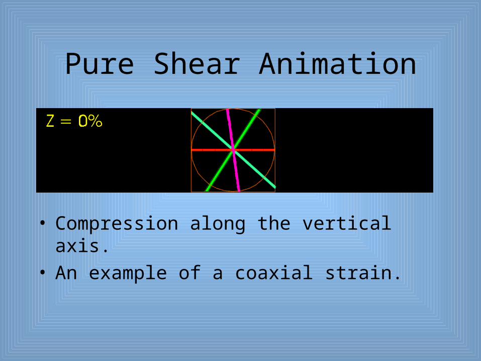
Pure Shear Animation
• Compression along the vertical axis.• An example of a coaxial strain.

Pure Shear Animation of Points
• Traces movement of material.
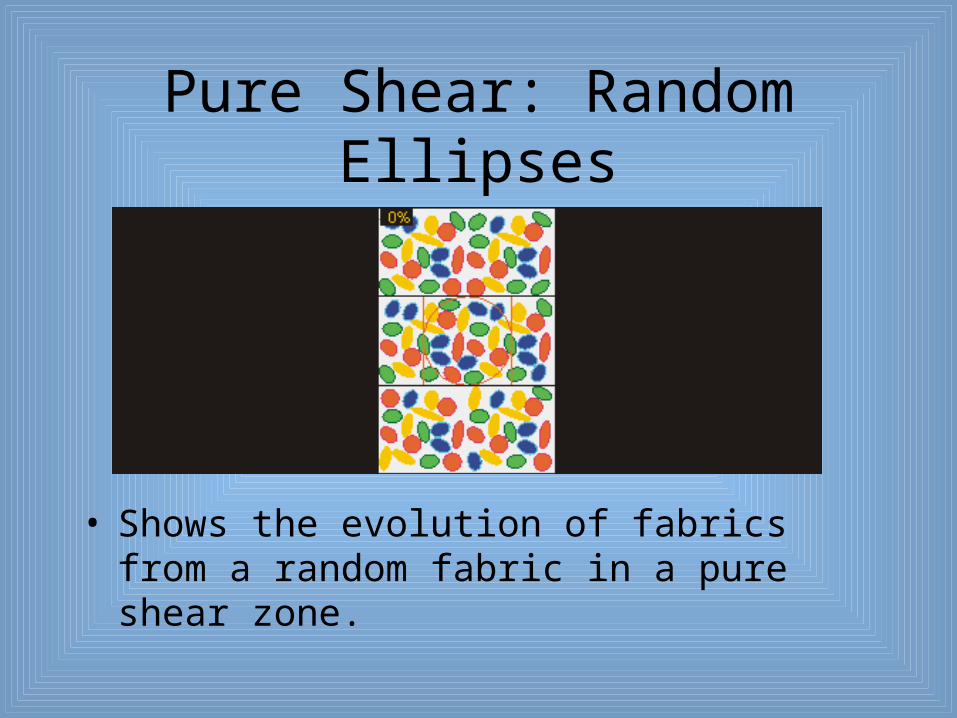
Pure Shear: Random Ellipses
• Shows the evolution of fabrics from a random fabric in a pure shear zone.

Simple Shear Animation
• Simple shear flow showing changes in orientation and length of lines.
• An example of a noncoaxial strain.

Simple Shear Animation of Points
Traces movement of material.

Simple Shear: Random Ellipses
• Shows the evolution of fabrics from a random fabric in a pure shear zone.

General Shear
• If a combination of simple shear and pure shear exists, it is known as general shear, and is noncoaxial
• Figure shows two types of general shear (a) is transtension (b) is transpression
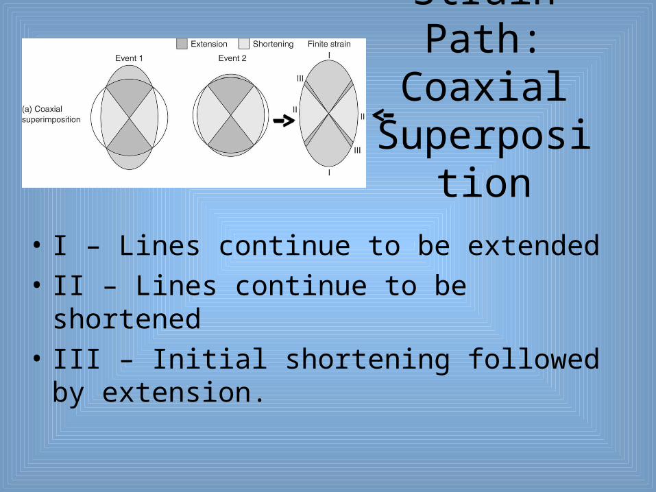
Strain Path: Coaxial
Superposition
• I – Lines continue to be extended
• II – Lines continue to be shortened
• III – Initial shortening followed by extension.
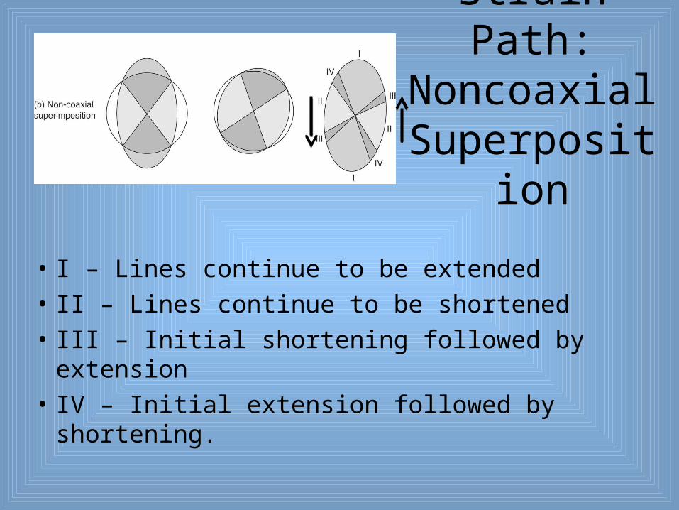
Strain Path: Noncoaxial
Superposition
• I – Lines continue to be extended
• II – Lines continue to be shortened
• III – Initial shortening followed by extension
• IV – Initial extension followed by shortening.

SPECIAL STRAIN STATE
• Some strain states that arise from various relationships between the principal strain axes, X, Y, and Z are:-
1. General strain (triaxial strain)
where X > Y > Z
and no volume change.

2. Axially symmetric elongation (extension)X > Y = Z
Prolate Shape (Cigar Shape)
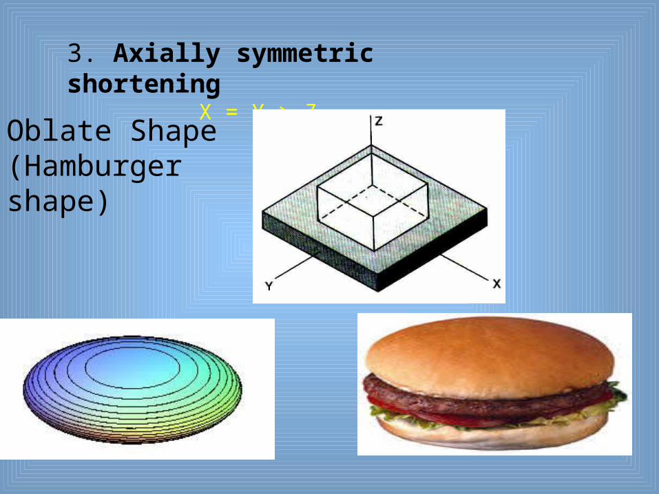
3. Axially symmetric shorteningX = Y > Z
Oblate Shape(Hamburger shape)

4. Plane Strain
X > Y(=1) > Z
5.1 (Simple shortening)
X= Y (=1) > Z
5.2 (Simple elongation)
X > Y = Z = 11+2+3+4 above have no volume change
5.1+5.2 include Change in volume ( 0)
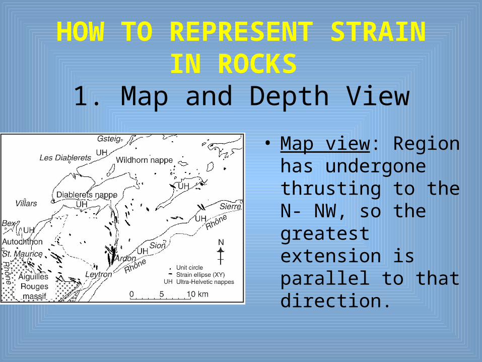
HOW TO REPRESENT STRAIN IN ROCKS
1. Map and Depth View
• Map view: Region has undergone thrusting to the N- NW, so the greatest extension is parallel to that direction.
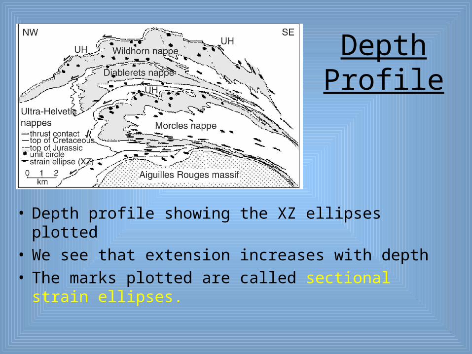
Depth Profile
• Depth profile showing the XZ ellipses plotted • We see that extension increases with depth• The marks plotted are called sectional strain ellipses.

HOW TO REPRESENT STRAIN IN ROCKS
2. Shape and Intensity by Flinn Diagram
• The Flinn diagram, named for British geologist Derek Flinn, is a plot of axial ratios
• In strain analysis, we typically use strain ratios, so this type of plot is very useful
• The horizontal axis is the ratio Y/Z = b (intermediate stretch/minimum stretch) and the vertical axis is X/Y = a (maximum stretch divided by intermediate stretch)
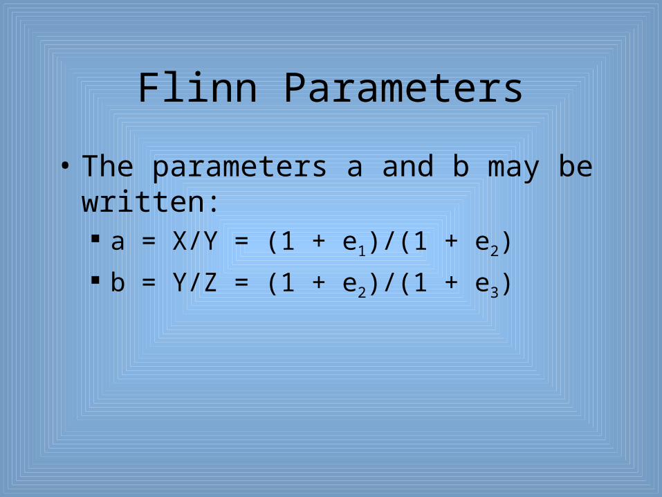
Flinn Parameters
• The parameters a and b may be written: a = X/Y = (1 + e1)/(1 + e2)
b = Y/Z = (1 + e2)/(1 + e3)
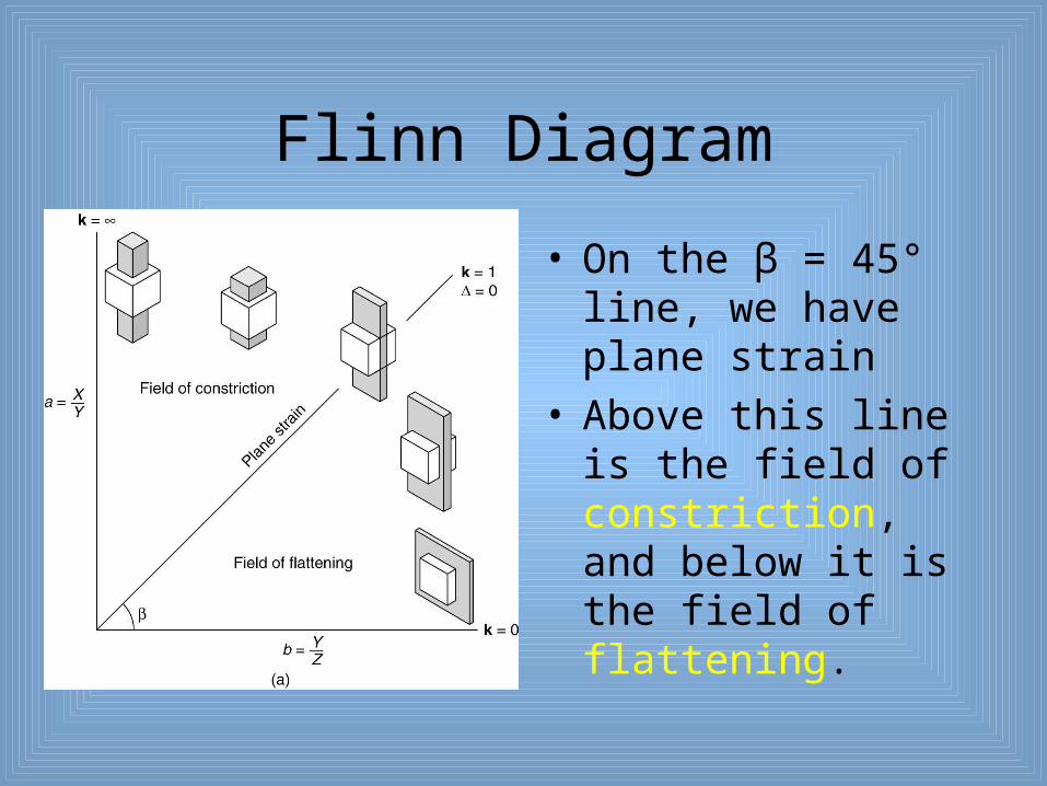
Flinn Diagram
• On the β = 45° line, we have plane strain
• Above this line is the field of constriction, and below it is the field of flattening.
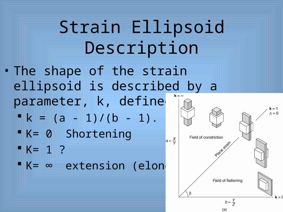
Strain Ellipsoid Description
• The shape of the strain ellipsoid is described by a parameter, k, defined as: k = (a - 1)/(b - 1). K= 0 Shortening K= 1 ? K= ∞ extension (elongation)

Flinn Diagram Modification
• A modification of the Flinn diagram is the Ramsey diagram, named after structural geologist John Ramsey.
• Ramsey used the natural log of (X/Y) and log of (Y/Z).

Mathematics of Modification
• Then, Mathematically modified to ln, ln a = ln (X/Y) = ln (1 + e1)/(1 + e2)
ln b = ln (Y/Z) = (1 + e2)/(1 + e3)
• From the definition of a logarithm, ln (X/Y) = lnX - lnY

STRAIN MARKERSPassive and Active marker
• Clay bed contains nodules of limestone
• Clay bed contains inclusion of granite.