chapter 4 a framework simulation in opnet modeler - …usir.salford.ac.uk/37055/9/9_chapter 4 a...
TRANSCRIPT
49
Chapter 4 A Framework Simulation in
OPNET Modeler
4.1 Introduction
In this chapter will present about a designed framework which simulating on OPNET
Modeler software. The research is simulating those techniques and designed processes on
OPNET Modeler software which is a licensing at University of Salford. OPNET Modeler
software is a network simulation software and solution. This software provides for
application and network management issues.
4.2 Network simulation
For doing research in the network field, network simulation software is a very useful and
important tool. As researchers or protocol designers have to design and testing the system in
simulation software before using it in a real network. There are many network simulations
that widely used in networking research such as OMNET++ (Objective Modular Network
Testbed in C++), NS-2 (Network Simulator version 2) and QualNet [69].
OPNET Modeler is generally used by researchers, developing protocol designers and so on.
The OPNET software was funded in 1986 by Alain Cohen. OPNET stands for Optimizing
Network Engineering Tools [70]. OPNET Modeler provides a comprehensive development
environment which is powerful for instance simulation, data analysis, model design and etc.
also it can support lot of technologies including local area network (LAN), mobile network,
sensor network, wireless network and so on.
4.2.1 Basic Structure within OPNET Modeler
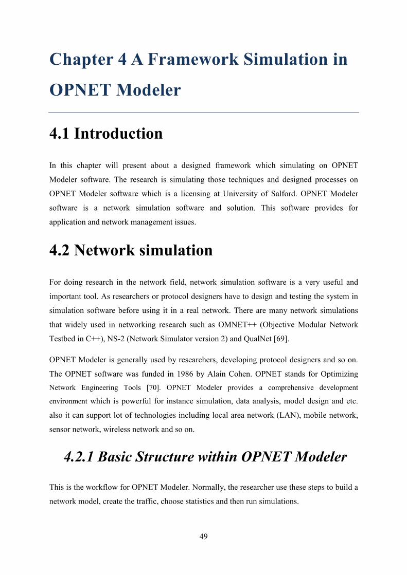
This is the workflow for OPNET Modeler. Normally, the researcher use these steps to build a
network model, create the traffic, choose statistics and then run simulations.
50
Figure 4-1 Basic step for creating network simulation
These 4 steps in Figure 4-1 consist of creating network environments which is including
network devices and traffic, and then choose statistics that we want to study. Next step is run
simulations. Finally, view and analyze the results. To complete these 4 steps, OPNET
Modeler provides variety kinds of editor to support users as show below.
The Project Editor
This is a main area of OPNET simulation. We use this area to create network topology,
generate traffic within network and view the results via this editor. Moreover, this area still
covers about choosing statistics and running simulations.
The Node Editor
The user can define the behavior of each network object via “Node Editor”. In Node Editor
of each model, the behavior is defined using different modules for example data storage, data
creation, etc. A network object in OPNET Modeler is typically building up from multiple
modules which define that object. The user can add their modules into the network object via
Node Editor.
A Network Model in the Project Editor
The OPNET Modeler let user to design and create any elements of network as they wish. For
instance, user can create node, link model, process models and build packet formats. Also,
the user can create filters and parameters that they want to analyze.
51
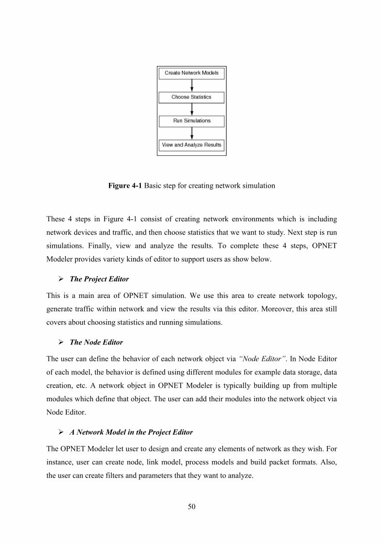
Node Model
Figure 4-2 Node Mode example
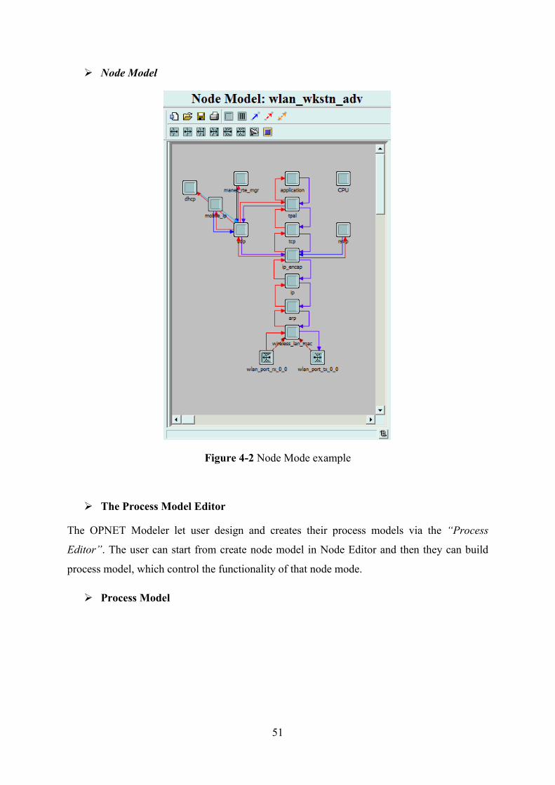
The Process Model Editor
The OPNET Modeler let user design and creates their process models via the “Process
Editor”. The user can start from create node model in Node Editor and then they can build
process model, which control the functionality of that node mode.
Process Model
52
Figure 4-3 Process Mode example
4.3 Implementation of the Proposed
Framework in OPNET Modeler
Due to the implementation of this research has been simulation environments and testing the
performance of designing on OPNET Modeler software version 16.0 which is not supported
multicast communication over IPv6 WiFi environment. Hence, the implementation and
development of this thesis has been modifying based on IPv4 environment. However, the
concept and designed of this framework can adapt to WiFi network both on IPv4 and IPv6
Networks.
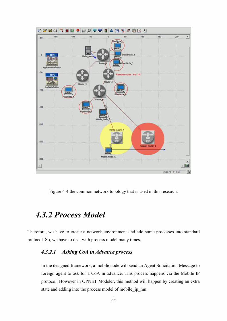
4.3.1 Network Architecture
Normally, the first thing that has to start network simulation is OPNET Modeler is to create
network architecture. The common start network topology that is used in this research is
shown in Figure 4-4.
53
Figure 4-4 the common network topology that is used in this research.
4.3.2 Process Model
Therefore, we have to create a network environment and add some processes into standard
protocol. So, we have to deal with process model many times.
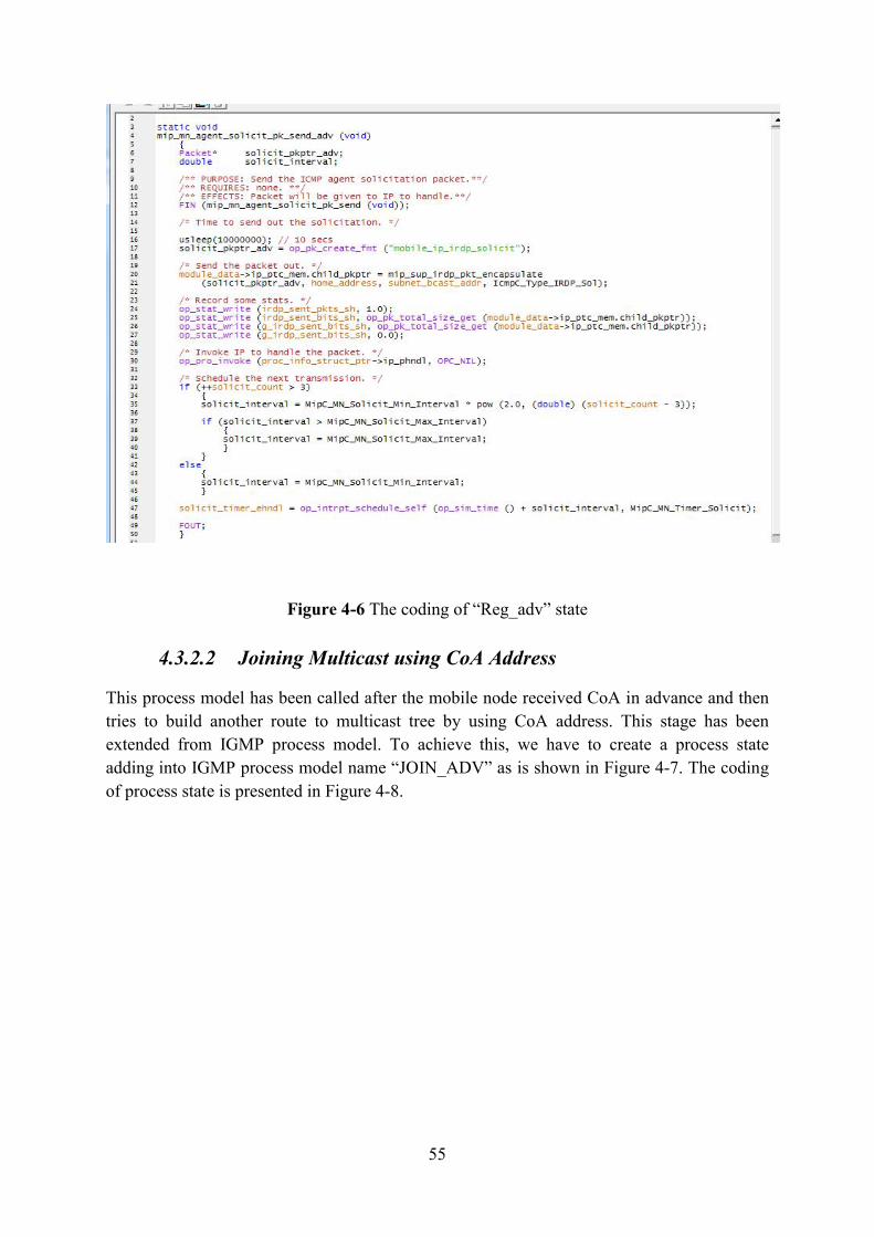
4.3.2.1 Asking CoA in Advance process
In the designed framework, a mobile node will send an Agent Solicitation Message to
foreign agent to ask for a CoA in advance. This process happens via the Mobile IP
protocol. However in OPNET Modeler, this method will happen by creating an extra
state and adding into the process model of mobile_ip_mn.

54
Figure 4-5 Process Model: mobile_ip_mn
Figure 4-5 is shown the Process Model of Mobile IP protocol within mobile node. To achieve
the process of asking CoA in advance, state name “Reg_adv” have to be added. The coding
of this state is shown in the Figure 4-6.
55
Figure 4-6 The coding of “Reg_adv” state
4.3.2.2 Joining Multicast using CoA Address
This process model has been called after the mobile node received CoA in advance and then
tries to build another route to multicast tree by using CoA address. This stage has been
extended from IGMP process model. To achieve this, we have to create a process state
adding into IGMP process model name “JOIN_ADV” as is shown in Figure 4-7. The coding
of process state is presented in Figure 4-8.

56
Figure 4-7 Process Model: IGMP host
Figure 4-8 The coding of “JOIN_ADV” state
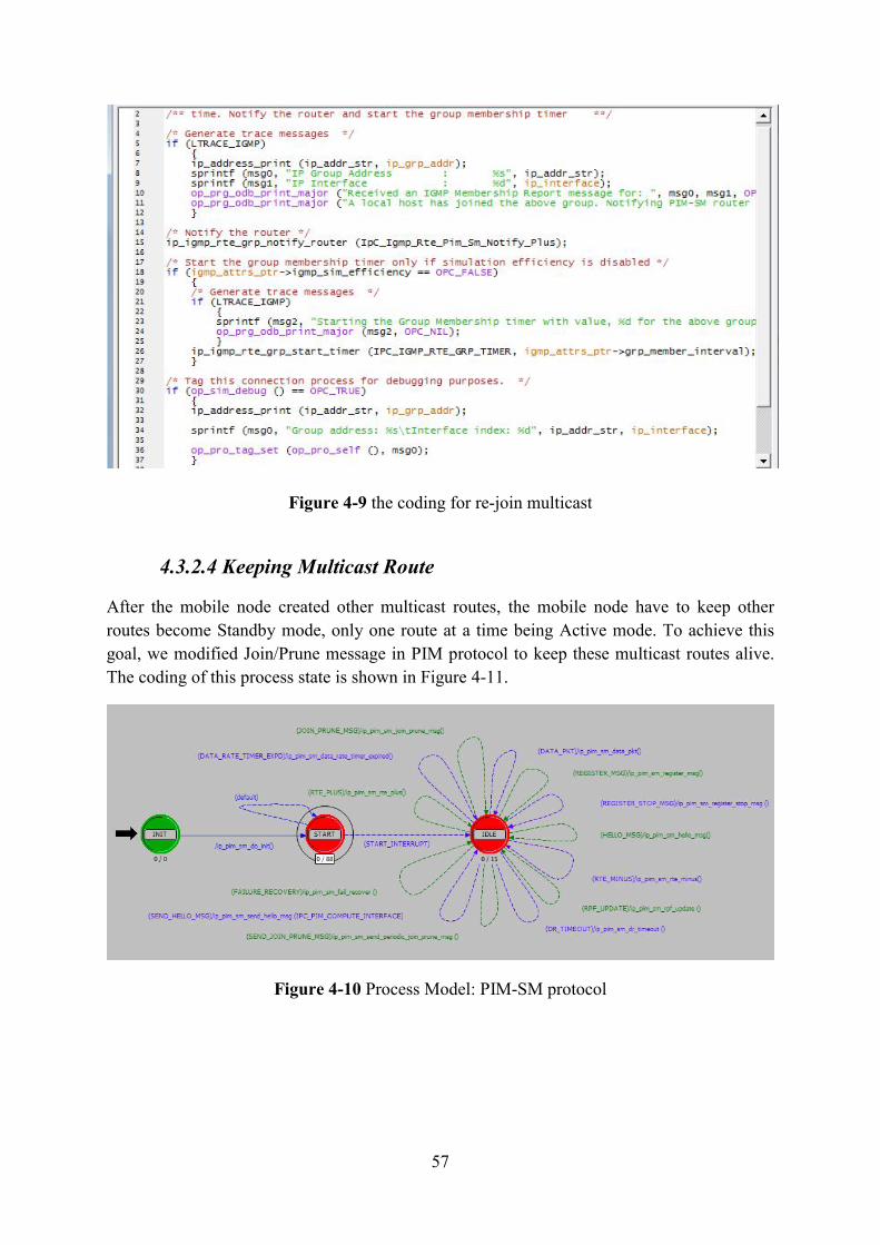
4.3.2.3 Re-join Multicast
When the mobile node has been realized that, now it is in a foreign agent. The process re-join
will call multicast joining state in process model “ip_igmp_rte_grp” to send a message to join
multicast group again.
57
Figure 4-9 the coding for re-join multicast
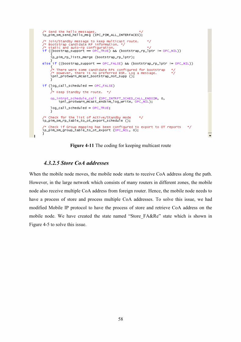
4.3.2.4 Keeping Multicast Route
After the mobile node created other multicast routes, the mobile node have to keep other
routes become Standby mode, only one route at a time being Active mode. To achieve this
goal, we modified Join/Prune message in PIM protocol to keep these multicast routes alive.
The coding of this process state is shown in Figure 4-11.
Figure 4-10 Process Model: PIM-SM protocol
58
Figure 4-11 The coding for keeping multicast route
4.3.2.5 Store CoA addresses
When the mobile node moves, the mobile node starts to receive CoA address along the path.
However, in the large network which consists of many routers in different zones, the mobile
node also receive multiple CoA address from foreign router. Hence, the mobile node needs to
have a process of store and process multiple CoA addresses. To solve this issue, we had
modified Mobile IP protocol to have the process of store and retrieve CoA address on the
mobile node. We have created the state named “Store_FA&Re” state which is shown in
Figure 4-5 to solve this issue.
59
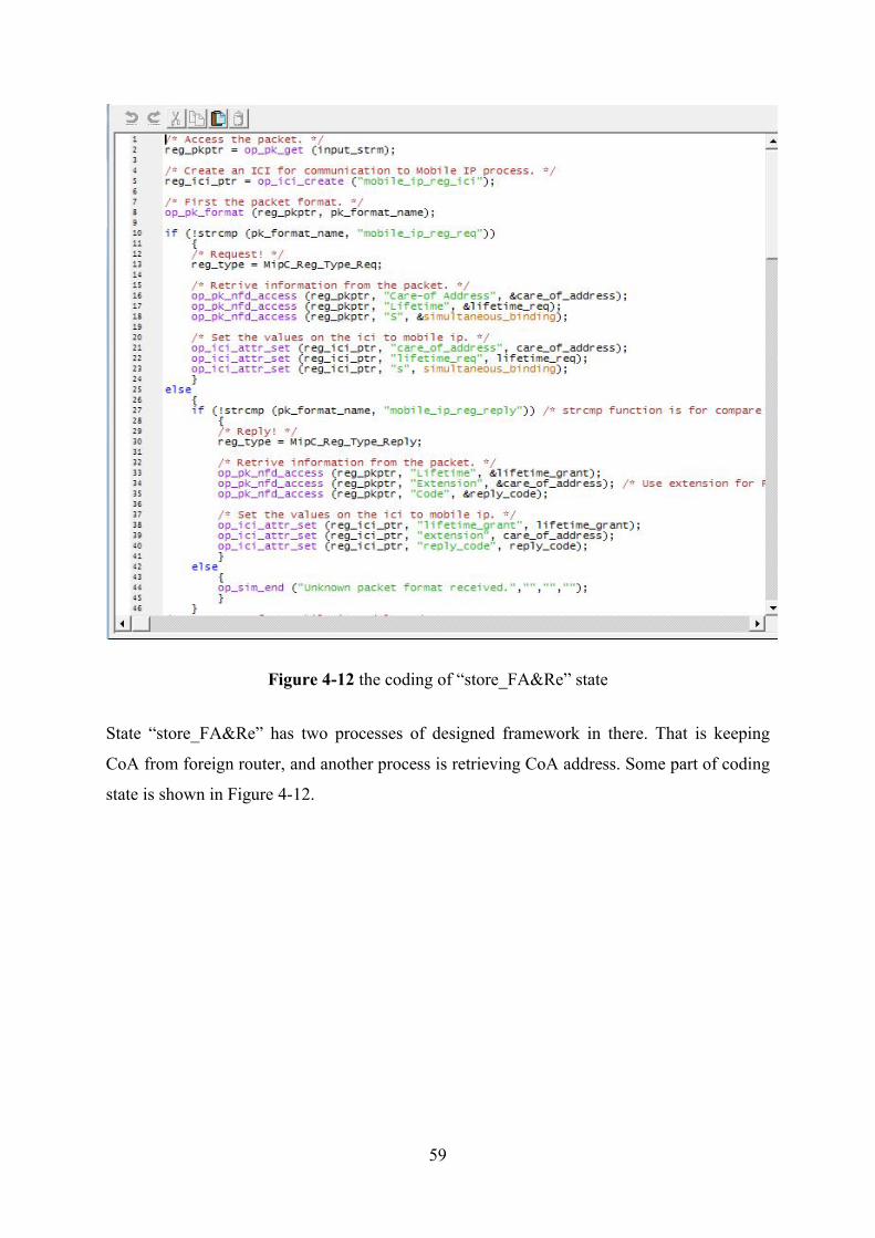
Figure 4-12 the coding of “store_FA&Re” state
State “store_FA&Re” has two processes of designed framework in there. That is keeping
CoA from foreign router, and another process is retrieving CoA address. Some part of coding
state is shown in Figure 4-12.
60
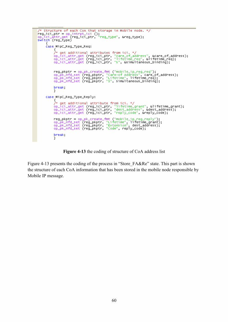
Figure 4-13 the coding of structure of CoA address list
Figure 4-13 presents the coding of the process in “Store_FA&Re” state. This part is shown
the structure of each CoA information that has been stored in the mobile node responsible by
Mobile IP message.
61
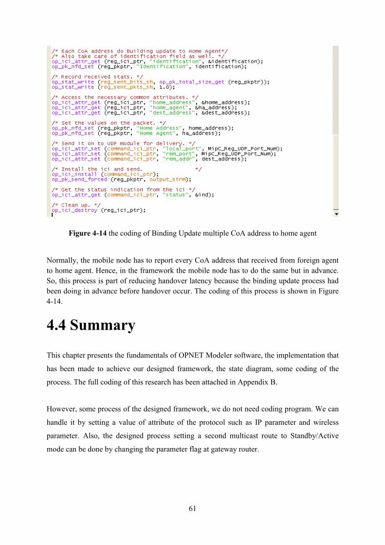
Figure 4-14 the coding of Binding Update multiple CoA address to home agent
Normally, the mobile node has to report every CoA address that received from foreign agent
to home agent. Hence, in the framework the mobile node has to do the same but in advance.
So, this process is part of reducing handover latency because the binding update process had
been doing in advance before handover occur. The coding of this process is shown in Figure
4-14.
4.4 Summary
This chapter presents the fundamentals of OPNET Modeler software, the implementation that
has been made to achieve our designed framework, the state diagram, some coding of the
process. The full coding of this research has been attached in Appendix B.
However, some process of the designed framework, we do not need coding program. We can
handle it by setting a value of attribute of the protocol such as IP parameter and wireless
parameter. Also, the designed process setting a second multicast route to Standby/Active
mode can be done by changing the parameter flag at gateway router.