chapter 3 · section 2 : carbon and low alloy steel pipes and fittings . 2.1 materials . 2.3 types...
TRANSCRIPT

2015

Rules & Regulations for the Construction & Classification of
Indian Coast Guard Ships
2015

Contents
Chapter 1 General
Chapter 2 Materials of Construction
Chapter 3 Design Loads
Chapter 4 Stability, Subdivision, Watertight and Weathertight Integrity
Chapter 5 Structures : Steel and Aluminium
Chapter 6 General Hull Requirements for Fibre Composite and Sandwich
Constructions
Chapter 7 Hull Appendages, Rudders and Steering Arrangement
Chapter 8 Anchoring and Mooring Equipment
Chapter 9 Fire Safety
Chapter 10 Piping Design Requirements
Chapter 11 Piping Systems
Chapter 12 Main and Auxiliary Machinery
Chapter 13 Electrical Installations
Chapter 14 Remote Control and Safety Systems
Chapter 15 Ships with Integrated Platform Management System
Chapter 16 Integrated Bridge System
Chapter 17 Dynamic Positioning Systems

Annexure - 1 Stability of Monohull Ships
Annexure - 2 Requirements and Compliance Criteria Related to Operational and Safety Performance
Annexure - 3
Factors to be considered in Determining Ship Operating Limitations
Rules and Regulations for the Construction and Classification of Indian Coast Guard Ships - 2015 Page 1 of 22
___________________________________________________________________________________
Contents
Chapter 1 : General
Section 1 : General Information 1.1 Indian Register of Shipping 1.2 Fees 1.3 Technical committee 1.4 Survey reports 1.5 Register of Ships 1.6 Liability 1.7 Audits and assessments by external organizations 1.8 Access of Surveyor to ships, shipyards or works 1.9 Requirements for service suppliers Section 2 : Application and Definitions 2.1 General 2.2 Application of Rules 2.3 Scope of classification 2.4 Interpretations of the Rules 2.5 Notations 2.6 Definitions 2.7 Character of classification 2.8 Class notations - Hull 2.9 Class notations - Machinery 2.10 Materials 2.11 Request for surveys 2.12 Classification of new constructions 2.13 Date of build 2.14 Appeal from Surveyors' recommendations 2.15 Certificates Appendix 1 : Table of characters of class and type notations, their expanded form and significance
Indian Register of Shipping

Contents Page 2 of 22
___________________________________________________________________________________
Chapter 2 : Materials of Construction
Section 1 : General 1.1 Scope Section 2 : Structural Steel 2.1 Manufacture, inspection and testing 2.2 Materials factor ‘k’ for steel 2.3 Grades of steel Section 3 : Structural Aluminium Alloy 3.1 Manufacture, inspection and testing 3.2 Material factor ‘k’ for aluminium alloys Section 4 : Glass Reinforced Plastic Materials 4.1 General 4.2 Procedure for approval of base materials 4.3 Glass fibre reinforcements 4.4 Polyester resins 4.5 Sandwinch core materials
Chapter 3 : Design Loads
Section 1 : General, Definition, Documentation 1.1 Scope and application 1.2 Definitions 1.3 Structural terms 1.4 Documentation Section 2 : Design Accelerations 2.1 Vertical acceleration
Indian Register of Shipping

Rules and Regulations for the Construction and Classification of Indian Coast Guard Ships - 2015 Page 3 of 22
___________________________________________________________________________________ Section 3 : Local Loads 3.1 General 3.2 Slamming pressure on bottom 3.3 Forebody side and bow impact pressure 3.4 Sea pressure 3.5 Loads on bulkheads 3.6 Pressure due to dry cargo, stores and equipment Section 4 : Global Loads 4.1 Longitudinal hull girder bending and shear loads
Chapter 4 : Stability, Subdivision, Watertight and Weathertight Integrity
Section 1 : General, Definitions, Documentation 1.1 Scope 1.2 Definitions 1.3 Documentation Section 2 : General Stability Requirements 2.1 General 2.2 Buoyant spaces 2.3 Intact stability in the displacement mode 2.4 Intact stability in the non-displacement mode 2.5 Intact stability in the transitional mode 2.6 Buoyancy and stability in the displacement mode following damage 2.7 Inclining and Stability Information 2.8 Loading and stability assessment 2.9 Damage control plan
Indian Register of Shipping

Contents Page 4 of 22
___________________________________________________________________________________
Section 3 : Watertight and Weathertight Integrity 3.1 Openings in watertight divisions 3.2 Indicators and surveillance 3.3 Integrity of superstructure Section 4 : Subdivision and Arrangement 4.1 Applicability 4.2 Transverse bulkheads 4.3 Cofferdams 4.4 Shell doors 4.5 Testing of hull structure 4.6 Ventilation, Air Pipes and Discharges 4.7 Bulwarks and Guard Rails 4.8 Other Openings and Weathertight Closing Appliances
Chapter 5 : Structures : Steel and Aluminium
Section 1 : Principles of Scantlings and Structural Details 1.1 Application 1.2 Symbols 1.3 Frame spacing 1.4 Stiffeners and girders 1.5 End attachments 1.6 Corrosion protection Section 2 : Hull Girder Strength 2.1 General 2.2 Hull section modulus 2.3 Openings in longitudinal strength members
Indian Register of Shipping

Rules and Regulations for the Construction and Classification of Indian Coast Guard Ships - 2015 Page 5 of 22
___________________________________________________________________________________ Section 3 : Plating 3.1 General 3.2 Bottom and bilge plating 3.3 Side plating 3.4 Deck plating 3.5 Bulkhead plating 3.6 Superstructure and deckhouse bulkheads, bulwarks 3.7 Hatch covers Section 4 : Secondary Stiffeners 4.1 General 4.2 Longitudinals 4.3 Frames 4.4 Bulkhead stiffeners 4.5 Superstructure and deckhouse bulkhead frames 4.6 Weather deck hatch cover stiffeners Section 5 : Primary Girders and Pillars 5.1 General 5.2 Bottom transverses and girders 5.3 Side webframes and stringers 5.4 Deck transverses and girders 5.5 Pillars Section 6 : Welding 6.1 General 6.2 Preparation for welding 6.3 Weld procedures and their approval 6.4 Inspection of welds 6.5 Butt welds 6.6 'T' connections 6.7 Lap connections
Indian Register of Shipping

Contents Page 6 of 22
___________________________________________________________________________________
6.8 Slot weld 6.9 End connection 6.10 Butt straps for aluminium alloy Section 7 : Direct Strength Analysis 7.1 General 7.2 Structural Analyses – Modeling & Procedure 7.3 Design Loads for Direct Strength Assessment 7.4 Analysis Criteria Section 8 : Helicopter Decks 8.1 General 8.2 Design Loads 8.3 Scantlings Section 9 : Vehicle Decks 9.1 General 9.2 Design Loads 9.3 Scantlings
Chapter 6 : General Hull Requirements for Fibre Composite and Sandwich Constructions
Section 1 : Principles of Scantlings and Structural Details 1.1 Application 1.2 Symbols 1.3 Frame spacing 1.4 Stiffeners and girders 1.5 End attachments 1.6 Bottom structures 1.7 Side structures 1.8 Deck structure
Indian Register of Shipping
Rules and Regulations for the Construction and Classification of Indian Coast Guard Ships - 2015 Page 7 of 22
___________________________________________________________________________________ 1.9 Bulkhead structures 1.10 Bow protection 1.11 Superstructures and deckhouses 1.12 Bulwarks Section 2 : Requirements for Manufacturing Facilities 2.1 Storage of raw materials 2.2 Manufacturing conditions Section 3 : Production Procedures, Workmanship and Manufacturing Control 3.1 General 3.2 Manual lamination 3.3 Spray moulding 3.4 Sandwich lay-up 3.5 Secondary bonding 3.6 Faults 3.7 Repair 3.8 Inspection 3.9 Acceptance criteria Section 4 : Details and Fastenings 4.1 General 4.2 Alignment 4.3 Continuity 4.4 Openings 4.5 Through bolting and bolted connections 4.6 Through hull fittings 4.7 Backing bars (inserts) and tapping plates 4.8 Exposed edges 4.9 Local reinforcement 4.10 Hull to deck connections 4.11 Exhaust systems
Indian Register of Shipping

Contents Page 8 of 22
___________________________________________________________________________________
4.12 Ballast 4.13 Limber holes 4.14 Integral tanks (requirements for coatings) 4.15 Reserve buoyancy Section 5 : Material Properties and Testing 5.1 Material properties 5.2 Testing Section 6 : Hull Girder Strength 6.1 General 6.2 Longitudinal bending strength 6.3 Calculation of effective sectional properties and longitudinal bending stress 6.4 Openings in longitudinal strength members 6.5 Shear Strength Section 7 : Sandwich Plate Panels 7.1 General 7.2 Sandwich core thickness 7.3 Sandwich laminate thickness Section 8 : Single Skin Plate Panels 8.1 General 8.2 Single skin laminate thickness Section 9 : Stiffeners, Primary Girders and Pillars 9.1 Applications 9.2 Strength requirements of stiffeners and girders 9.3 Pillars
Indian Register of Shipping

Rules and Regulations for the Construction and Classification of Indian Coast Guard Ships - 2015 Page 9 of 22
___________________________________________________________________________________
Chapter 7 : Hull Appendages, Rudders and Steering Arrangement
Section 1 : General Requirements 1.1 Scope 1.2 Materials Section 2 : Bar Keel, Stem and Stern Frames 2.1 General 2.2 Bar keel and stem 2.3 Stern frames 2.4 Sole piece Section 3 : Shaft Brackets Section 4 : Rudders Section 5 : Fin Stabilizers 5.1 General 5.2 Design loads 5.3 Fin stabilizer construction Section 6 : Steering Gear Systems 6.1 Scope 6.2 General 6.3 Definitions 6.4 Plans and documents 6.5 Materials 6.6 Rudder, rudder stock, vanes, tiller and quadrant 6.7 Requirements for design and performance 6.8 Mechanical steering gear 6.9 Control and monitoring
Indian Register of Shipping

Contents Page 10 of 22
___________________________________________________________________________________
Section 7 : Water Jet Installations 7.1 Waterjet propulsion systems – Construction 7.2 Waterjet systems – Installation 7.3 Design loads 7.4 Allowable stresses
Chapter 8 : Anchoring and Mooring Equipment
Section 1 : General 1.1 Introduction 1.2 Documentation Section 2 : Structural Arrangements for Anchoring Equipment 2.1 General Section 3 : Equipment Specification 3.2 Equipment Section 4 : Anchors 4.1 General 4.2 HHP (SHHP) anchors 4.3 Manufacture and testing Section 5 : Anchor Chain Cables 5.1 General 5.2 Manufacture and testing Section 6 : Towlines and Mooring Lines 6.1 General 6.2 Manufacture and testing 6.3 Mooring arrangement 6.4 Towing arrangements
Indian Register of Shipping

Rules and Regulations for the Construction and Classification of Indian Coast Guard Ships - 2015 Page 11 of 22
___________________________________________________________________________________ Section 7 : Windlass and Chain Stoppers 7.1 General 7.2 Testing
Chapter 9 : Fire Safety
Section 1 : General 1.1 Application 1.2 Documentation 1.3 General Principles 1.4 Definitions Section 2 : Structural Fire Protection 2.1 Main structure 2.2 Classification of space use 2.3 Structural arrangements and outfit Section 3 : Fuel and other Flammable Fluid Tanks and Systems Section 4 : Ventilation Section 5 : Fire Detection and Extinguishing Systems 5.1 Fire detection systems 5.2 Fixed fire extinguishing systems 5.3 Portable fire extinguishers 5.4 Fire pumps and fire mains 5.5 Hydrants and hoses 5.6 Shore connections 5.7 Weapons, magazines and ammunition spaces 5.8 Protection of deep-fat cooking equipment Section 6 : Protection of Ro-Ro Spaces 6.1 Structural fire protection of Ro-Ro spaces 6.2 Fixed fire-extinguishing system for Ro-Ro spaces
Indian Register of Shipping
Contents Page 12 of 22
___________________________________________________________________________________
6.3 Fire patrols and detection in Ro-Ro spaces 6.4 Fire extinguishing equipment in Ro-Ro spaces 6.5 Ventilation system of Ro-Ro spaces 6.6 Scuppers, bilge pumping and drainage of Ro-Ro spaces 6.7 Precautions against ignition of flammable vapours 6.8 Open Ro-Ro spaces Section 7 : Fire Protection of Helicopter Facilities Section 8 : Escape 8.1 Notification to crew 8.2 Means of escape Section 9 : Fire Control Plans Section 10 : Fireman’s Outfits Section 11 : Fire Safety Systems Code Section 12 : Fire Safety Requirements for Small Ships less than 500 GT 12.1 Purpose 12.1 General requirements/Application 12.2 Submission of plans and information 12.3 Definitions 12.4 Fire pumps and fire main system 12.5 Fire extinguishers 12.6 Fire extinguishing arrangements in machinery spaces 12.7 Special arrangements in machinery spaces 12.8 Arrangement of oil fuel, lubricating oil and other flammable oils 12.9 Fireman’s outfit/axe 12.10 Miscellaneous items 12.11 Fire safety measures for the ship
Indian Register of Shipping

Rules and Regulations for the Construction and Classification of Indian Coast Guard Ships - 2015 Page 13 of 22
___________________________________________________________________________________
Chapter 10 : Piping Design Requirements
Section 1 : General 1.1 Scope 1.2 Classes of pipes 1.3 Design pressure 1.4 Design temperature 1.5 Design symbols 1.6 Heat treatment 1.7 Minimum thickness of pipes and bends 1.8 Flanges 1.9 Materials Section 2 : Carbon and Low Alloy Steel Pipes and Fittings 2.1 Materials 2.3 Types of connection 2.4 Flange connections 2.5 Threaded sleeve joints 2.6 Welding, non-destructive examination and post-weld heat treatment of welded pipes 2.7 Mechanical joints Section 3: Copper and Copper Alloy Pipes and Fittings 3.1 Materials 3.2 Minimum thickness of pipes 3.3 Heat treatment Section 4 : Cast Iron Pipes and Fittings 4.1 Spheroidal or nodular graphite cast iron 4.2 Grey cast iron Section 5 : Plastic Pipes and Fittings 5.1 General
Indian Register of Shipping

Contents Page 14 of 22
___________________________________________________________________________________
Section 6 : Flexible Hoses 6.1 General 6.2 Applications Section 7 : Expansion Bellows 7.1 Design and construction requirements 7.2 Applications Section 8 : Hydraulic Tests on Pipes and Fittings 8.1 Hydraulic tests before installation on board 8.2 Testing after assembly on board
Chapter 11 : Piping Systems
Section 1 : Bilge, Ballast, Air Pipes and Sounding Systems 1.1 Application 1.2 Shell Valves and Fittings (other than those on scuppers and sanitary discharges) 1.3 Bilge Pumping and Drainage Systems 1.4 Air, Overflow and Sounding Pipes 1.5 Requirements for Ships less than 150 GT Section 2 : Machinery Piping Systems 2.1 Application 2.2 Oil Fuel Storage 2.3 Oil Fuel Systems 2.4 Low Flash Point Fuels 2.5 Lubricating / Hydraulic Oil Systems 2.6 Engine Cooling Water Systems 2.7 Requirements for Ships of less than 150 GT
Indian Register of Shipping

Rules and Regulations for the Construction and Classification of Indian Coast Guard Ships - 2015 Page 15 of 22
___________________________________________________________________________________
Chapter 12 : Main and Auxiliary Machinery
Section 1 : General Requirements for Machinery 1.1 Application 1.2 General 1.3 Fuel flash point 1.4 Exhaust 1.5 Bearings 1.6 Vibration of shaft systems 1.7 Alternative system of survey 1.8 Submission of information/ Plans 1.9 Certification of materials 1.10 Specifications 1.11 Certification of materials of construction 1.12 Operating control 1.13 Inclination of the ship 1.14 Securing of machinery 1.15 Collision load 1.16 Resilient mounts 1.17 Machinery mounted on resin chocks 1.18 Ventilation system 1.19 Recovery from dead ship condition 1.20 Operating conditions 1.21 Securing of machinery 1.22 Ventilation of machinery spaces 1.23 Surveys during construction 1.24 Sea trials
Indian Register of Shipping

Contents Page 16 of 22
___________________________________________________________________________________
Section 2 : Propulsion Shafting Systems 2.1 General requirements 2.2 Power ratings 2.3 Clutches 2.4 Safety 2.5 Plans 2.6 Calculations and specifications 2.7 Materials for shafts 2.8 Design and Construction 2.9 Vibration and alignment 2.10 Protection of propeller shafts 2.11 Control and Monitoring 2.12 Construction Section 3 : Prime Mover and Gearing 3.1 Diesel Engines 3.2 Gas Turbine 3.3 Gearing Section 4 : Propeller, Thruster, Water Jet System 4.1 Propeller 4.2 Thruster 4.3 Water Jet System Section 5 : Pressure Vessels 5.1 Application 5.2 Details to be submitted 5.3 Materials 5.4 Design pressure 5.5 Metal temperature 5.6 Design and construction
Indian Register of Shipping

Rules and Regulations for the Construction and Classification of Indian Coast Guard Ships - 2015 Page 17 of 22
___________________________________________________________________________________ 5.7 Mountings and Fittings for Pressure Vessels 5.8 Hydraulic tests 5.9 Fibre Reinforced Plastics Pressure Vessels 5.10 Requirements for Ships of less than 150 GT
Chapter 13 : Electrical Installations
Section 1 : General Requirements 1.1 General Section 2 : Requirements for Ships less than 500 GT 2.1 General requirements 2.2 Plans 2.3 Trials 2.4 Addition or alterations 2.5 Location and construction of equipment 2.6 Systems of distribution 2.7 Earthing 2.8 Protection 2.9 Quality of power supplies 2.10 Generators 2.11 Cables 2.12 Batteries 2.13 Lightning conductors
Indian Register of Shipping

Contents Page 18 of 22
___________________________________________________________________________________
Chapter 14 : Remote Control and Safety Systems
Section 1 : General 1.1 General Section 2 : Requirements for Ships less than 500 GT 2.1 Plans and information 2.2 Remote control of propulsion machinery 2.3 Periodically unattended machinery spaces (if installed) Section 3 : Tests and Trials 3.1 General 3.2 Directional control system 3.3 Stabilization system
Chapter 15 : Ships with Integrated Platform Management System
Section 1 : General 1.1 Scope 1.2 Main Features 1.3 Assumptions 1.4 Plans and particulars 1.5 Signboards and instruction manuals 1.6 Spares Section 2 : System Design 2.1 General 2.2 Control stations 2.3 Control systems 2.4 Alarm systems 2.5 Safety systems 2.6 Automatic start of pumps
Indian Register of Shipping

Rules and Regulations for the Construction and Classification of Indian Coast Guard Ships - 2015 Page 19 of 22
___________________________________________________________________________________ 2.7 Automatic start/connection of diesel generator units by Automated Power Management System (APMS) 2.8 Automatic stop of auxiliary engines 2.9 Automatic stop of propulsion machinery 2.10 Automatic stop of oil fired auxiliary boilers 2.11 Re-establishment of propulsion after blackout 2.12 Communications 2.13 Fire detection and alarm systems Section 3 : Ships fitted with Internal Combustion Propulsion Engines of 1000[kW] or more 3.1 Extent of monitoring 3.2 Electric power supply Section 4 : Ships fitted with Internal Combustion Propulsion Engines of less than 1000 [kW] 4.1 General 4.2 Alarm system 4.3 Arrangements on bridge 4.4 Electric power supply Section 5 : Precautions against Fire 5.1 Oil fuel systems 5.2 Fire detection 5.3 Fire detector indicator panel Section 6 : Testing of the System 6.1 Testing at supplier’s works 6.2 Environmental testing 6.3 Factory Acceptance Trials
6.4 Shipboard installation and trials 6.5 Monitoring systems 6.6 Automatic and remote control systems 6.7 Blackout test
Indian Register of Shipping

Contents Page 20 of 22
___________________________________________________________________________________
Chapter 16 : Integrated Bridge System
Section 1 : General 1.1 Application 1.2 Functional requirements 1.3 International standards and IMO requirements 1.4 Definitions 1.5 Abbreviations 1.6 Equipment list Section 2 : Documentation 2.1 Documents to be submitted Section 3 : System Requirements 3.1 General 3.2 Integration 3.3 Data exchange and data logging 3.4 Failure analysis 3.5 Quality Assurance 3.6 Alarm management 3.7 Power system requirement 3.8 Communication systems 3.9 Environmental conditions 3.10 EMI / EMC Section 4 : Operational and Technical Requirements 4.1 Human factors 4.2 Bridge layout 4.3 Lighting 4.4 Field of vision 4.5 Training
Indian Register of Shipping

Rules and Regulations for the Construction and Classification of Indian Coast Guard Ships - 2015 Page 21 of 22
___________________________________________________________________________________ Section 5 : Work Station 5.1 General 5.2 Navigation workstation Section 6 : Navigational Equipment Requirements Section 7 : Bridge Navigational Watch Alarm System Section 8 : Tests and Trials 8.1 General
Chapter 17 : Dynamic Positioning Systems
Section 1 : General 1.1 Scope, application 1.2 Definitions 1.3 Classification notations : definition and general principles 1.4 Summary of requirements for various class notations 1.5 Information and plans required to be submitted 1.6 Performance capability of the DP system Section 2 : Thruster System 2.1 General 2.2 Thruster system 2.3 Emergency stop Section 3 : Power Systems 3.1 General 3.2 Generators 3.3 Distribution arrangements 3.4 Control system power supply 3.5 Auxiliary supplies
Indian Register of Shipping
Contents Page 22 of 22
___________________________________________________________________________________
Section 4 : DP - Control System 4.1 General 4.2 System arrangement and functions 4.3 Position reference systems and environmental sensors 4.4 Alarms 4.5 Internal Communication Section 5 : Tests and Trials 5.1 General
ANNEXURES Annexure – 1 : Stability of Monohull Ships 1. Stability criteria in the intact condition (Applicable to all monohull ships of Indian Coast Guard). 2. Criteria for residual stability after damage Annexure – 2 : Requirements and Compliance Criteria Related to Operational and Safety Performance 1. Performance 2. Stopping 3. Cruise performance 4. Effects of failures or malfunction Annexure – 3 : Factors to be considered in Determining Ship Operating Limitations 1. Purpose and Scope 2. Factors to be considered
End of Chapter
Indian Register of Shipping

Rules and Regulations for the Construction and Classification of Indian Coast Guard Ships – 2015 Page 1 of 14
_________________________________________________________________________________
Chapter 1
General
Contents
Section
1 General Information
2
Application and Definitions
Section 1
General Information
1.1 Indian Register of Shipping 1.1.1 Indian Register of Shipping (hereinafter referred to as "IRS") was incorporated in 1975 as a Public Limited Company under Section 25 of the Indian Companies Act, 1956 for the purpose of providing amongst other things a faithful and accurate classification of mercantile shipping classed with it, to approve designs of, to survey and to issue reports on mercantile and non mercantile ships, hovercrafts, hydrofoils etc; all within the scope of classification described in the Rules. This Section contains General Regulations which have been adopted by IRS for its governance. 1.1.2 The management of the affairs of IRS are carried out under the direction and control of the Board of Directors (hereinafter referred to as the 'Board'), in accordance with the provisions of its Memorandum and Articles of Association. 1.1.3 The Board of Directors shall consist of representative of the interests of various members of the Company and those concerned with shipping in general as under: 3 Directors representing Indian Shipowners 2 Directors representing Indian Shipbuilders 1 Director representing General Insurance Corporation of India and other Indian underwriters 1 Director being the Director General of Shipping, Ministry of Surface Transport, Govt. of India 1 Director representing Ship Design Research and Development Institutions 1 Director representing Manufacturers of Marine Engines/General Engineering Goods 1 Director representing Indian Navy/Coast Guard 1 Director being a person of eminence from the field of Law 3 Directors being persons of eminence from any industry allied with maritime activities 1 Managing Director being full-time employee appointed by the Board of Directors. The composition of the Board as above is to be in accordance with the Articles of Association of IRS (as may be amended from time to time).
Indian Register of Shipping

Chapter 1 : General Page 2 of 14
1.1.4 The Board shall consist of not less than six and not more than fifteen Directors. The Board of Directors shall elect one of its members to be Chairman of the Board of Directors. 1.1.5 The Board is to appoint a Sub-Committee of Classification representing concerned interests. 1.1.6 The Board is to appoint the Chairman of the Sub-Committee of Classification and the Managing Director, IRS to be 'ex- officio' member of the Sub-Committee of Classification. 1.1.7 The employees of IRS are to be appointed by and be under the direction of the Board. 1.1.8 The Surveyors of IRS are not to be permitted without the special sanction of the Board of Directors to receive any fee, gratuity or reward whatsoever, for their own use or benefit, for any service performed by them in their capacity as Surveyors to IRS, except on pain of immediate dismissal. 1.1.9 The Funds and Accounts are to be under the authority and control of the Board of Directors. 1.2 Fees 1.2.1 Fees will be charged for all surveys and for other services rendered by IRS or any of its publications in accordance with established scales. Traveling expenses incurred by the Surveyors in connection with such services are also chargeable. 1.3 Technical committee 1.3.1 The Board appoints a Technical Committee whose function will be to consider :
a) Formulation of Technical Rules for Classification Surveys, building of ships, their machinery and equipment.
b) Important alterations to Rules once framed as may be required from time to time.
1.3.2 All decisions of the Technical Committee including amendments and/or additions to the Rules for classification surveys and building of ships' hull, their machinery and equipment to be reported to the Board of Directors. 1.3.3 The Technical Committee to be constituted as follows: Number of Members Nominees/Representatives of 3 Board of Directors of IRS 1 Marine Engine Unit of M/s. Garden Reach Ship-builders and Engineers Ltd. 1 Other Marine Engine Builders 6 Shipbuilders 2 Indian Institution of Naval Architects 2 Institute of Marine Engineers (India) 1 Company of Master Mariners 2 Directorate General of Shipping 1 IMU(Earlier NSDRC) 4 Indian National Shipowners Association
Indian Register of Shipping

Rules and Regulations for the Construction and Classification of Indian Coast Guard Ships – 2015 Page 3 of 14
_________________________________________________________________________________
1 Institution of Engineers (India) 1 Ex-Officio - Managing Director of IRS or his nominee 1 Indian Coastal Conference Shipping Association 1 Oil Industry Safety Directorate 5 Indian Navy 2 Indian Coast Guard 1 Research Institutes 2 Indian Institute of Technology/ National Institute of Technology
2 Maritime Training Institutes 3 Other Flag Administrations 1 Inland Waterways Authority of India 1.3.4 In addition to the foregoing, the Technical Committee may co-opt to the main body other members of high managerial positions in Ship Building and Engineering, Naval Architecture, Marine Insurance, Steel Making, etc. 1.3.5 Nomination of all members to the Technical Committee to be subject to confirmation by the Board. 1.3.6 The Technical Committee can appoint panels from amongst its body to which representatives of any organisation or industry or individuals specialised in relevant disciplines could be co-opted for the purpose of considering any particular Technical problem or area of Rules. 1.3.7 The Board of Directors to appoint biennially, the Chairman of the Technical Committee and the Technical Committee to appoint from their own body biennially a Vice-Chairman. The appointment of Vice-Chairman is to be confirmed by the Board of Directors. 1.3.8 The terms of office of all members to be not more than four years, one-fourth of all members (including those co-opted) to retire at the end of each calender year. The members so retiring being those who have been longest in office since their last nomination and such members to be eligible for re-nomination for a second term. Unless specially so authorised by the Board of Directors, no member other than Chairman and/or Vice- Chairman, who has served for two periods of nomination, is to be eligible for re-nomination. In the event of any vacancy occurring before the expiration of the normal term of office, a representative to be nominated to fill the vacancy from the same group/body/institution and for such nominee the date of his nomination by the respective body to be considered as date of his joining the Technical Committee for purposes of his retirement by rotation. 1.3.9 The meeting of the Technical Committee to be convened as often and at such time and place as may appear necessary, but there shall be at least two meetings in each year. 1.3.10 The members desiring to propose alterations in, or additions to the Rules for the classification, survey or building of ship (hull and machinery) shall give notice of such proposals to the Secretary. Every meeting to be convened by notice from the Secretary, if possible one month before the date of the meeting and the Secretary to send to each member an Agenda paper as soon as possible thereafter. Proposals for changes to rules may also be given by Flag Administrations, shipowners, shipbuilders and other interested parties who may not be represented in the Technical Committee 1.3.11 The quorum for any meeting of Technical committee will be six members, with at least 50% of the members present being those who do not have or represent any interest in commercial shipping.
Indian Register of Shipping
Chapter 1 : General Page 4 of 14
1.3.12 In the event that any matter is not decided by unanimity, the same may be decided by a majority of votes cast in favor, with each member, including co-opted members, having one vote only. In the event of a parity of votes, the Chairman of the Technical Committee would be entitled to an additional casting vote. 1.3.13 When any discussion relates to an item of interest to those connected with commercial shipping (representatives of commercial ship owning or ship building organizations), such representatives would not be entitled to vote, if such matter is to be decided by voting. 1.3.14 In the event that any member of the Technical Committee absents himself for 3 consecutive meetings of the Technical Committee without seeking leave of absence, he would be deemed to have vacated office and his vacancy would be filled by seeking fresh nomination from concerned interest represented. 1.3.15 In the absence of the Chairman & the Vice Chairman of the Technical Committee, the members of the Technical committee shall elect a Chairman, by majority vote, to preside over that particular meeting only. 1.3.16 The Board of Directors reserves to themselves the right of altering, adding to or rescinding any/or all of the above terms of reference including the dissolution of the Technical Committee. 1.4 Survey reports 1.4.1 All reports of survey are to be made by the Surveyors according to the form prescribed and submitted for consideration of the Board or the Sub-Committee of Classification, but the character assigned by the latter is to be reported to the Board. The Board may, in specified instances, vest in the Managing Director discretionary powers to act on its behalf, and all such actions being reported to the Board at its subsequent meeting. 1.4.2 The reports of the Surveyors shall, subject to the approval of the Managing Director, be open to inspection of the Owner and any other person authorised in writing by the Owner. Copies of the reports will, subject to the approval of the Managing Director, be supplied to Owners or their representatives. 1.5 Register of Ships 1.5.1 A Register of ships is available on-line on the IRCLASS website which contains the names of ships, character of class and notations assigned together with other relevant useful information for ships classed with IRS. 1.6 Liability 1.6.1 Whilst Indian Register of Shipping (hereinafter referred to as IRS) and its Board/Committees use their best endeavours to ensure that the functions of IRS are properly carried out, in providing services, information or advice, neither IRS nor any of its servants or agents warrants the accuracy of any information or advice supplied. Except as set out herein, neither IRS nor any of its servants or agents (on behalf of each of whom IRS has agreed this clause) shall be liable for any loss damage or expense whatever sustained by any person due to any act or omission or error of whatsoever nature and howsoever caused of IRS, its servants or agents or due to any inaccuracy of whatsoever nature and howsoever caused in any information or advice given in any way whatsoever by or on behalf of IRS, even if held to amount to a breach of warranty. Nevertheless, if any person uses services of IRS, or relies on any information or advice given by or on behalf of IRS and suffers loss, damage or expenses thereby which is proved to have been due to any negligent act omission or error of IRS its servants or agents or any negligent inaccuracy in information or advice given by or on behalf of IRS then IRS will pay compensation to such person for his proved loss up to but not exceeding the amount of the fee charged by IRS for that particular service, information or advice. 1.6.2 Any notice of claim for loss, damage or expense as referred to in 1.6.1 shall be made in writing to IRS Head Office within six months of the date when the service, information or advice was first
Indian Register of Shipping

Rules and Regulations for the Construction and Classification of Indian Coast Guard Ships – 2015 Page 5 of 14
_________________________________________________________________________________
provided, failing which all the rights to any such claim shall be forfeited and IRS shall be relieved and discharged from all liabilities. 1.7 Audits and assessments by external organizations 1.7.1 The surveys required by the regulations, and conducted by IRS may be subject to Audit by an independent Accredited Certification Body (ACB) as per the requirements of ISO 9001:2008 standard and Quality Management System Certification Scheme (QSCS) of IACS. For this purpose, ACB auditors are to be given the necessary access to the ship, shipyard or works when requested by IRS Access is also to be given to auditors or inspectors accompanying the surveyors as required by other external organizations 1.8 Access of Surveyor to ships, shipyards or works 1.8.1 The Surveyors are to be given free access to ships classed with IRS as well as to shipyards, works, etc. so as to perform their duties, and are to receive adequate assistance for this purpose. 1.9 Requirements for service suppliers 1.9.1 Firms providing following services on behalf of the Owner, the results of which are used by Surveyors in making decision affecting classification and/or affecting statutory certifications, are to be approved by IRS in accordance with the laid down procedures. a) Class services
- Firms engaged in thickness measurements on ships
- Firms engaged in tightness testing of hatches with ultrasonic equipment
- Firms carrying out in-water survey of ships.
- Firm engaged in the examination of bow, stern and inner doors b) Statutory services
- Firms engaged in surveys and maintenance of fire extinguishing equipment and systems
- Firms engaged in service on inflatable liferafts, inflatable lifejackets, hydrostatic release units, etc.
- Firms engaged in the servicing and testing of radio communication equipment
- Firms engaged in inspection and testing of centralised gas welding and cutting equipment
- Firms engaged in surveys and maintenance of self contained breathing apparatus.
- Firm engaged in sound pressure level measurements of public address and general alarm
system
- Firms engaged in testing of coating systems in accordance with the requirements of IMO performance standards for protective coating.
Indian Register of Shipping
Chapter 1 : General Page 6 of 14
Section 2
Application and Definitions
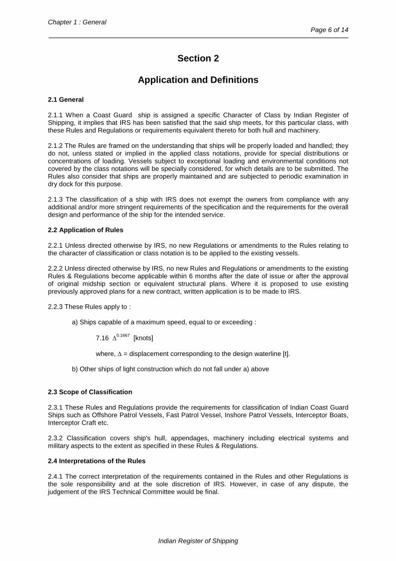
2.1 General 2.1.1 When a Coast Guard ship is assigned a specific Character of Class by Indian Register of Shipping, it implies that IRS has been satisfied that the said ship meets, for this particular class, with these Rules and Regulations or requirements equivalent thereto for both hull and machinery. 2.1.2 The Rules are framed on the understanding that ships will be properly loaded and handled; they do not, unless stated or implied in the applied class notations, provide for special distributions or concentrations of loading. Vessels subject to exceptional loading and environmental conditions not covered by the class notations will be specially considered, for which details are to be submitted. The Rules also consider that ships are properly maintained and are subjected to periodic examination in dry dock for this purpose. 2.1.3 The classification of a ship with IRS does not exempt the owners from compliance with any additional and/or more stringent requirements of the specification and the requirements for the overall design and performance of the ship for the intended service. 2.2 Application of Rules 2.2.1 Unless directed otherwise by IRS, no new Regulations or amendments to the Rules relating to the character of classification or class notation is to be applied to the existing vessels. 2.2.2 Unless directed otherwise by IRS, no new Rules and Regulations or amendments to the existing Rules & Regulations become applicable within 6 months after the date of issue or after the approval of original midship section or equivalent structural plans. Where it is proposed to use existing previously approved plans for a new contract, written application is to be made to IRS. 2.2.3 These Rules apply to :
a) Ships capable of a maximum speed, equal to or exceeding :
7.16 ∆0.1667 [knots]
where, ∆ = displacement corresponding to the design waterline [t].
b) Other ships of light construction which do not fall under a) above
2.3 Scope of Classification 2.3.1 These Rules and Regulations provide the requirements for classification of Indian Coast Guard Ships such as Offshore Patrol Vessels, Fast Patrol Vessel, Inshore Patrol Vessels, Interceptor Boats, Interceptor Craft etc. 2.3.2 Classification covers ship's hull, appendages, machinery including electrical systems and military aspects to the extent as specified in these Rules & Regulations. 2.4 Interpretations of the Rules 2.4.1 The correct interpretation of the requirements contained in the Rules and other Regulations is the sole responsibility and at the sole discretion of IRS. However, in case of any dispute, the judgement of the IRS Technical Committee would be final.
Indian Register of Shipping

Rules and Regulations for the Construction and Classification of Indian Coast Guard Ships – 2015 Page 7 of 14
_________________________________________________________________________________
2.5 Notations 2.5.1 Type Notation: A descriptive notation indicating the type of Coast Guard ship according to its intended purpose of operation. Any special requirement applicable to a particular type of ship is specified in the rules.e.g. Offshore Patrol Vessel, Inshore Patrol Vessel etc. 2.5.2 Special Feature Notation : A notation indicating that the ship incorporates special features which significantly affect the design. 2.5.3 Service Area Restriction Notation: A notation indicating that a ship has been classed on the understanding that it will be operated only in suitable areas or conditions which have been agreed to by IRS e.g. "RS-0". 2.6 Definitions 2.6.1 Assembly Station is an area where crew can be gathered in the event of an emergency, given instructions and prepared to abandon the Ship, if necessary. The crew spaces may serve as assembly stations if all crew can be instructed there and prepared to abandon the ship. 2.6.2 Auxiliary Machinery Spaces are spaces containing internal combustion engines of power output upto and including 110 kW driving generators, sprinkler, drencher or fire pumps, bilge pumps, etc., oil filling stations, switchboards of aggregate capacity exceeding 800 kW, similar spaces and trunks to such spaces. 2.6.3 Auxiliary Machinery Spaces having little or no fire risk are spaces containing refrigerating, stabilizing, ventilation and air conditioning machinery, switchboards of aggregate capacity 800 kW or less, similar spaces and trunks to such spaces. 2.6.4 Breadth (B) means breadth [m] of the broadest part of the moulded watertight envelope of the rigid hull, excluding appendages, at or below the design waterline in the displacement mode with no lift or propulsion machinery active. 2.6.5 Continuously Manned Control Station is a control station which is continuously manned by a responsible member of the crew while the ship is in normal service. 2.6.6 Control Stations are those spaces in which the ship’s radio or navigating equipment (main displays and controls for equipment) or the emergency source of power and emergency switchboard are located, or where the fire recording or fire control equipment is centralized, or where other functions essential to the safe operation of the ship such as propulsion control, public address, stabilization systems, etc., are located. 2.6.7 Crew Accommodation are those spaces allocated for the use of the crew, and include cabins, sick bays, offices, lavatories, lounges and similar spaces. 2.6.8 Critical Design Conditions means the limiting specified conditions chosen for design purposes, which the ship should keep in displacement mode. Such conditions should be more severe than the worst intended conditions by a suitable margin to provide for adequate safety in survival condition. 2.6.9 Datum means a watertight deck or equivalent structure of a non-watertight deck covered by a weathertight structure of adequate strength to maintain the weathertight integrity and fitted with weathertight closing appliances. 2.6.10 Design Waterline means the waterline corresponding to the maximum operational weight of the ship with no lift or propulsion machinery active and is limited by the stability and strength requirements in the Rules. 2.6.11 Displacement Mode means the regime, whether at rest or in motion, where the weight of the ship is fully or predominantly supported by hydrostatic forces.
Indian Register of Shipping

Chapter 1 : General Page 8 of 14
2.6.12 Failure Mode and Effect Analysis (FMEA) is an examination of the ship’s systems and equipment to determine whether any reasonably probable failure or improper operation can result in a hazardous or catastrophic effect. 2.6.13 Fire Test Procedures Code (FTP Code) means the International Code for Application of Fire Test Procedures, as defined in chapter II-2 of the SOLAS Convention. 2.6.14 Flash-point means a flash-point determined by a test using the closed cup apparatus. 2.6.15 Galleys are those enclosed spaces containing cooking facilities with exposed heating surfaces, or which have any cooking or food heating appliances each having a power of more than 5 [kW]. 2.6.16 High Speed Craft is a ship capable of maximum speed equal to or exceeding:
7.16 ∆0.1667 [knots]
where,∆ = displacement corresponding to the design waterline [t]. 2.6.17 IMO means the International Maritime Organisation. 2.6.18 Length (L) means the overall length [m] of the underwater watertight envelope of the rigid hull, excluding appendages, at or below the design waterline in the displacement mode with no lift or propulsion machinery active. 2.6.19 Lightweight is the displacement of the ship[t] without cargo, fuel, lubricating oil, ballast water, fresh water and feed-water in tanks, consumable stores, passengers and crew and their effects. 2.6.20 Light Craft is a ship of light construction, which does not fall in the category of ships defined by 2.6.16. 2.6.21 Machinery Spaces are spaces containing internal combustion engines either used for main propulsion or having an aggregate total power output of more than 110 kW, generators, oil fuel units, major electrical machinery and similar spaces and trunks to such spaces. 2.6.22 Maximum Operational Weight means the overall weight upto which the ship will be operated in the intended mode. 2.6.23 Maximum Speed V [knots] is the speed achieved at the maximum continuous propulsion power for which the ship is certified at maximum operational weight and in smooth water. 2.6.24 Non-Displacement Mode means the normal operational regime of a ship when non hydrostatic forces substantially or predominantly support the weight of the ship. 2.6.25 Oil Fuel Unit is the equipment used for the preparation of oil fuel for delivery to an oil-fired boiler, or equipment used for the preparation for delivery of heated oil to an internal combustion engine, and includes any oil pressure pumps, filters and heaters dealing with oil at a pressure of more than 0.18 [N/mm2]. 2.6.26 Open ro-ro spaces are spaces:
a) to which any personnel have access; and
b) which either:
i) are open at both ends, or
Indian Register of Shipping

Rules and Regulations for the Construction and Classification of Indian Coast Guard Ships – 2015 Page 9 of 14
_________________________________________________________________________________
ii) have an opening at one end and are provided with permanent openings distributed in the side plating or deckhead or from above, having a total area of at least 10% of the total area of the space sides.
2.6.27 Operating Compartment means the enclosed area from which the navigation and control of the ship is exercised. 2.6.28 Operating Station means a confined area of the operating compartment equipped with necessary means for navigation, manoeuvring and communication, and from where the functions of navigating, manoeuvring, communication, commanding, conning and lookout are carried out. 2.6.29 Passenger is every person other than:
a) the master and members of the crew or other persons employed or engaged in any capacity on board a ship on the business of that ship; and
b) a child under one year of age. 2.6.30 Place of Refuge is any naturally or artificially sheltered area which may be used as a shelter by a ship under conditions likely to endanger its safety. 2.6.31 Public Spaces include bars, smoke rooms, main seating areas, lounges, dining rooms, recreation rooms, lobbies, lavatories and similar permanently enclosed spaces allocated to passengers. 2.6.32 Ro-ro Ship is a ship fitted with one or more ro-ro spaces. 2.6.33 Ro-ro Spaces are spaces not normally subdivided in any way and normally extending to either a substantial length or the entire length of the ship in which motor vehicles with fuel in their tanks for their own propulsion and/or goods (packaged or in bulk, in or on rail or road cars, vehicles (including road or rail tankers), trailers, containers, pallets, demountable tanks or in or on similar stowage units or other receptacles) can be loaded and unloaded, normally in a horizontal direction. 2.6.34 Service Spaces are those enclosed spaces used for pantries containing food warming equipment but not cooking facilities with exposed heating surfaces, lockers, storerooms and enclosed baggage rooms. Such spaces containing no cooking appliances may contain:
.1 coffee automats, toasters, dish washers, microwave ovens, water boilers and similar appliances, each of them with a maximum power of 5 [kW]; and
.2 electrically heated cooking plates and hot plates for keeping food warm, each of them with a maximum power of 2 kW and a surface temperature not above 150°C.
2.6.35 Significant Wave Height is the average crest-to-trough height of the highest one third of the zero-upcrossing waves in a specified period 2.6.36 SOLAS 74 means the International Convention for Safety of Life at Sea, 1974, as amended. 2.6.37 Transitional Mode means the regime between displacement and non-displacement modes. 2.6.38 Watertight in relation to a structure means capable of preventing the passage of water through the structure in any direction under the head of water likely to occur in the intact or damaged condition. 2.6.39 Weather Deck is a deck which is completely exposed to the weather from above and at least two sides. 2.6.40 Weathertight means that water will not penetrate into the ship in any wind and wave conditions up to those specified as critical design conditions.
Indian Register of Shipping
Chapter 1 : General Page 10 of 14
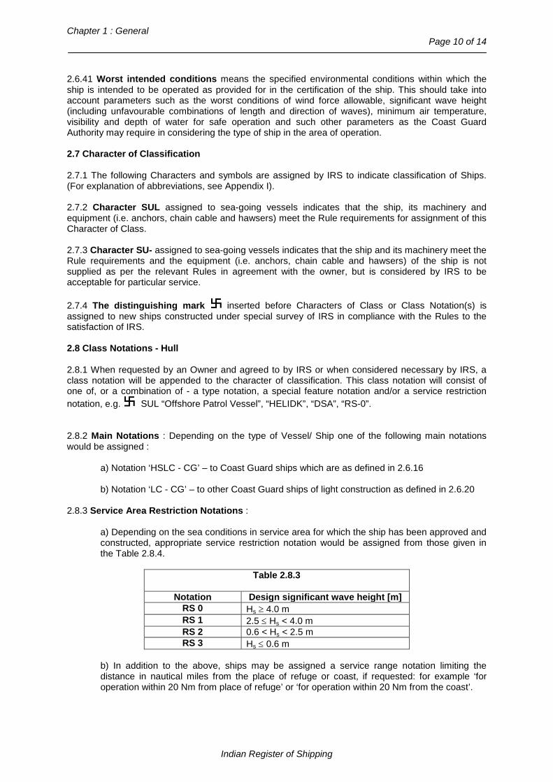
2.6.41 Worst intended conditions means the specified environmental conditions within which the ship is intended to be operated as provided for in the certification of the ship. This should take into account parameters such as the worst conditions of wind force allowable, significant wave height (including unfavourable combinations of length and direction of waves), minimum air temperature, visibility and depth of water for safe operation and such other parameters as the Coast Guard Authority may require in considering the type of ship in the area of operation. 2.7 Character of Classification 2.7.1 The following Characters and symbols are assigned by IRS to indicate classification of Ships. (For explanation of abbreviations, see Appendix I). 2.7.2 Character SUL assigned to sea-going vessels indicates that the ship, its machinery and equipment (i.e. anchors, chain cable and hawsers) meet the Rule requirements for assignment of this Character of Class. 2.7.3 Character SU- assigned to sea-going vessels indicates that the ship and its machinery meet the Rule requirements and the equipment (i.e. anchors, chain cable and hawsers) of the ship is not supplied as per the relevant Rules in agreement with the owner, but is considered by IRS to be acceptable for particular service. 2.7.4 The distinguishing mark inserted before Characters of Class or Class Notation(s) is assigned to new ships constructed under special survey of IRS in compliance with the Rules to the satisfaction of IRS. 2.8 Class Notations - Hull 2.8.1 When requested by an Owner and agreed to by IRS or when considered necessary by IRS, a class notation will be appended to the character of classification. This class notation will consist of one of, or a combination of - a type notation, a special feature notation and/or a service restriction notation, e.g. SUL “Offshore Patrol Vessel”, “HELIDK”, “DSA”, “RS-0”. 2.8.2 Main Notations : Depending on the type of Vessel/ Ship one of the following main notations would be assigned : a) Notation ‘HSLC - CG’ – to Coast Guard ships which are as defined in 2.6.16 b) Notation ‘LC - CG’ – to other Coast Guard ships of light construction as defined in 2.6.20 2.8.3 Service Area Restriction Notations :
a) Depending on the sea conditions in service area for which the ship has been approved and constructed, appropriate service restriction notation would be assigned from those given in the Table 2.8.4.
Table 2.8.3
Notation Design significant wave height [m] RS 0 Hs ≥ 4.0 m RS 1 2.5 ≤ Hs < 4.0 m RS 2 0.6 < Hs < 2.5 m RS 3 Hs ≤ 0.6 m
b) In addition to the above, ships may be assigned a service range notation limiting the distance in nautical miles from the place of refuge or coast, if requested: for example ‘for operation within 20 Nm from place of refuge’ or ‘for operation within 20 Nm from the coast’.
Indian Register of Shipping
Rules and Regulations for the Construction and Classification of Indian Coast Guard Ships – 2015 Page 11 of 14
_________________________________________________________________________________
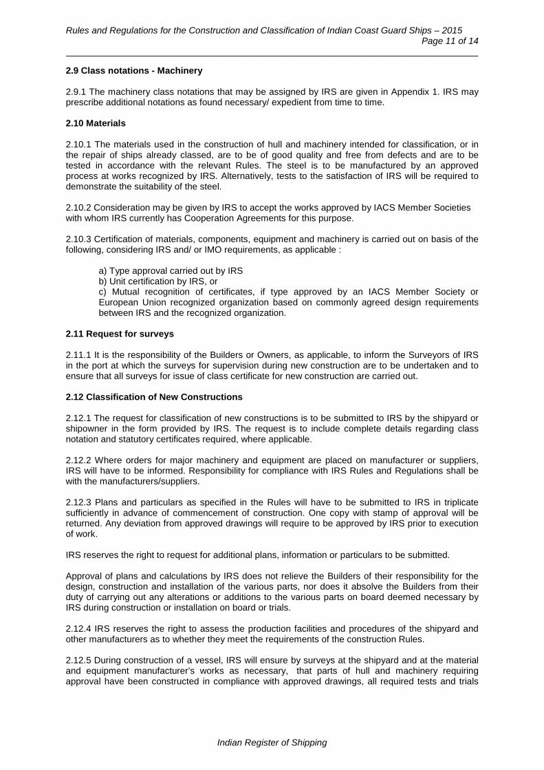
2.9 Class notations - Machinery 2.9.1 The machinery class notations that may be assigned by IRS are given in Appendix 1. IRS may prescribe additional notations as found necessary/ expedient from time to time. 2.10 Materials 2.10.1 The materials used in the construction of hull and machinery intended for classification, or in the repair of ships already classed, are to be of good quality and free from defects and are to be tested in accordance with the relevant Rules. The steel is to be manufactured by an approved process at works recognized by IRS. Alternatively, tests to the satisfaction of IRS will be required to demonstrate the suitability of the steel. 2.10.2 Consideration may be given by IRS to accept the works approved by IACS Member Societies with whom IRS currently has Cooperation Agreements for this purpose. 2.10.3 Certification of materials, components, equipment and machinery is carried out on basis of the following, considering IRS and/ or IMO requirements, as applicable :
a) Type approval carried out by IRS b) Unit certification by IRS, or c) Mutual recognition of certificates, if type approved by an IACS Member Society or European Union recognized organization based on commonly agreed design requirements between IRS and the recognized organization.
2.11 Request for surveys 2.11.1 It is the responsibility of the Builders or Owners, as applicable, to inform the Surveyors of IRS in the port at which the surveys for supervision during new construction are to be undertaken and to ensure that all surveys for issue of class certificate for new construction are carried out. 2.12 Classification of New Constructions 2.12.1 The request for classification of new constructions is to be submitted to IRS by the shipyard or shipowner in the form provided by IRS. The request is to include complete details regarding class notation and statutory certificates required, where applicable. 2.12.2 Where orders for major machinery and equipment are placed on manufacturer or suppliers, IRS will have to be informed. Responsibility for compliance with IRS Rules and Regulations shall be with the manufacturers/suppliers. 2.12.3 Plans and particulars as specified in the Rules will have to be submitted to IRS in triplicate sufficiently in advance of commencement of construction. One copy with stamp of approval will be returned. Any deviation from approved drawings will require to be approved by IRS prior to execution of work. IRS reserves the right to request for additional plans, information or particulars to be submitted. Approval of plans and calculations by IRS does not relieve the Builders of their responsibility for the design, construction and installation of the various parts, nor does it absolve the Builders from their duty of carrying out any alterations or additions to the various parts on board deemed necessary by IRS during construction or installation on board or trials. 2.12.4 IRS reserves the right to assess the production facilities and procedures of the shipyard and other manufacturers as to whether they meet the requirements of the construction Rules. 2.12.5 During construction of a vessel, IRS will ensure by surveys at the shipyard and at the material and equipment manufacturer’s works as necessary, that parts of hull and machinery requiring approval have been constructed in compliance with approved drawings, all required tests and trials
Indian Register of Shipping

Chapter 1 : General Page 12 of 14
are performed satisfactorily, workmanship is in compliance with current engineering practices and welded parts are produced by qualified welders. 2.12.6 All hull, machinery and electrical installations will be subjected to operational trials in the presence of IRS Surveyor. 2.12.7 On completion of the ship copies of as fitted plans showing the ship as built, essential certificates and records, loading manual etc. are to be submitted by the Builder generally prior to issuance of the Interim Certificate of Class. 2.13 Date of build 2.13.1 The date of completion of the special survey inspection will normally be taken as the date of build to be entered in the Register Book. Where there is a substantial delay between completion of construction survey and the ship commencing service, the date of commissioning may be specified on the classification certificate. When modifications are carried out on a ship, the initial date of build remains assigned to the ship. 2.13.2 When a complete replacement or addition of a major portion of the ship (e.g. fwd.section, midship section or aft section) is involved, the following applies:
- Date of build assigned to each portion of the ship will be indicated on the classification certificate, and the date of modification will be indicated in the Register Book.
- Survey requirements shall be based on the date of build associated with each major portion of
the ship. 2.14 Appeal from Surveyors' recommendations 2.14.1 If the recommendations of the Surveyors are considered in any case to be unnecessary or unreasonable, appeal may be made to IRS, who may direct a special examination to be held. 2.15 Certificates 2.15.1 Certificates of Class will be issued to Builders or Owners when the required reports on completion of Special Surveys of new ships or of existing ships submitted for classification have been received from the Surveyors and approved by IRS. 2.15.2 Certificates of class maintenance in respect of completed periodical special surveys of hull and machinery will also be issued to Owners. 2.15.3 The Surveyors are permitted to issue Interim Certificates to enable a ship, classed with IRS, to proceed on her voyage provided that, in their opinion, she is in a fit and efficient condition. Such Certificates will contain Surveyors' recommendations for continuance of Class, but in all cases are subject to confirmation by IRS. 2.15.4 Individual Certificates can also be issued for propelling machinery, boilers, equipments and fittings which have been manufactured under IRS Survey and in accordance with these Regulations.
Indian Register of Shipping

Rules and Regulations for the Construction and Classification of Indian Coast Guard Ships – 2015 Page 13 of 14
_________________________________________________________________________________
Appendix 1 Table of characters of class and type notations, their expanded form and significance
Abbreviation Expanded Form Significance
Characters of Class
SUL SARVOUTAM LANGER Denotes vessels which are classed with Indian Register of Shipping
SU- SARVOUTAM
Denotes vessels which are classed with IRS when the anchoring and mooring equipment of the ship is not supplied as per the relevant Rules, in agreement with the Owner, but is considered by IRS to be acceptable for particular service
SWASTIKA
This distinguishing mark inserted before Characters of Class or Class Notations is assigned to new ships constructed under special survey of IRS in compliance with the Rules to the satisfaction of IRS
Class Notations – Hull
RS-0 RESTRICTED SERVICE-0 Service in areas with significant wave height greater than or equal to 4 [m]
RS-1 RESTRICTED SERVICE- 1 Service in areas with significant wave height ranging from 2.5 [m] to 4 [m]
RS-2 RESTRICTED SERVICE-2 Service in areas with significant wave height ranging from 0.6 [m] to 2.5 [m]
RS-3 RESTRICTED SERVICE -3 Service in areas with significant wave height not greater than 0.6 [m]
RS-“Specified area”
RESTRICTED SERVICE-“Specified area”
Restricted service in a specified geographical area. The geographical area will form part of the class notation.
HELIDK
This notation will be assigned for vessels with erected platforms or landing area designed for helicopter landings in accordance with applicable requirements of the Rules
DSA (Seastate, Speed)
DIRECT STRENGTH ASSESSMENT (Seastate,
Speed)
This notation will be assigned when direct calculations for strength have been carried out for a specified Seastate and Speed combination in accordance with the Rule requirements
INWATER SURVEY Denotes that the examination of the ship's bottom and related items may be carried out while the ship is afloat
SMM STRESS AND MOTION MONITORING
Denotes that sensors and arrangement are provided for monitoring hull girder stresses and vertical accelerations of the vessel at sea.
HCM HULL CONDITION MONITORING
Denotes that a computer and related software are available on board for recording and analysis of the ship’s hull thickness measurement and other survey data.
Indian Register of Shipping
Chapter 1 : General Page 14 of 14
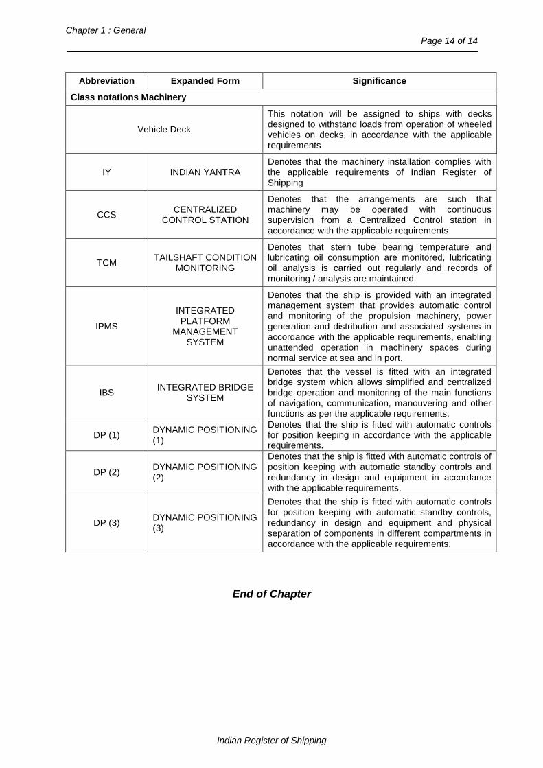
Abbreviation Expanded Form Significance
Class notations Machinery
Vehicle Deck
This notation will be assigned to ships with decks designed to withstand loads from operation of wheeled vehicles on decks, in accordance with the applicable requirements
IY INDIAN YANTRA Denotes that the machinery installation complies with the applicable requirements of Indian Register of Shipping
CCS CENTRALIZED CONTROL STATION
Denotes that the arrangements are such that machinery may be operated with continuous supervision from a Centralized Control station in accordance with the applicable requirements
TCM TAILSHAFT CONDITION MONITORING
Denotes that stern tube bearing temperature and lubricating oil consumption are monitored, lubricating oil analysis is carried out regularly and records of monitoring / analysis are maintained.
IPMS
INTEGRATED PLATFORM
MANAGEMENT SYSTEM
Denotes that the ship is provided with an integrated management system that provides automatic control and monitoring of the propulsion machinery, power generation and distribution and associated systems in accordance with the applicable requirements, enabling unattended operation in machinery spaces during normal service at sea and in port.
IBS INTEGRATED BRIDGE SYSTEM
Denotes that the vessel is fitted with an integrated bridge system which allows simplified and centralized bridge operation and monitoring of the main functions of navigation, communication, manouvering and other functions as per the applicable requirements.
DP (1) DYNAMIC POSITIONING (1)
Denotes that the ship is fitted with automatic controls for position keeping in accordance with the applicable requirements.
DP (2) DYNAMIC POSITIONING (2)
Denotes that the ship is fitted with automatic controls of position keeping with automatic standby controls and redundancy in design and equipment in accordance with the applicable requirements.
DP (3) DYNAMIC POSITIONING (3)
Denotes that the ship is fitted with automatic controls for position keeping with automatic standby controls, redundancy in design and equipment and physical separation of components in different compartments in accordance with the applicable requirements.
End of Chapter
Indian Register of Shipping

Rules and Regulations for the Construction and Classification of Indian Coast Guard Ships - 2015
Page 1 of 8
Chapter 2
Materials of Construction
Contents Section
1 General
2 Structural Steel
3 Structural Aluminium Alloy
4 Glass Reinforced Plastic Materials
Section 1
General
1.1 Scope 1.1.1 These Rules provide for use of steel, marine grade aluminium alloys and glass fibre reinforced plastics in the construction or repair of hull structures. These materials are to be tested and inspected according to the requirements given in Sections 2, 3 and 4 respectively. 1.1.2 Materials used for the construction or repair of machinery systems or components are to be manufactured tested and inspected according to the relevant requirements given in Part 2 of the Rules and Regulations for the Construction and Classification of Steel Ships. 1.1.3 Materials complying with recognised national or international standards giving equivalent requirements may also be accepted.
Section 2
Structural Steel
2.1 Manufacture, inspection and testing 2.1.1 All steel rolled products, castings and forgings used in the construction or repairs of the hull structures are to be manufactured and tested in accordance with the requirements of Chapters 3, 4 and 5, respectively of Part 2 of the Rules and Regulations for the Construction and Classification of Steel Ships. 2.2 Material factor ‘k’ for steel 2.2.1 Ordinary hull structural steel is a hull structural steel with a minimum yield stress of 235 [N/mm2] and a tensile strength generally in the range of 400-490 [N/mm2]. For ordinary hull structural steel, the material factor ‘k’ is to be taken as 1.0.
Indian Register of Shipping

Chapter 2 : Materials of Construction
Page 2 of 8 2.2.2 Steels having a yield stress of 315 [N/mm2] and higher, are regarded as higher tensile steels. Where higher tensile steel is used, the hull girder section modulus and the local scantlings may be reduced in accordance with the relevant requirement of the Rules. For this purpose, a material factor ‘k’, is to be taken as follows: k = 0.78 for steel with a minimum yield stress of 315 [N/mm2]. k = 0.72 for steel with a minimum yield stress of 355 [N/mm2]. k = 0.68 for steel with minimum yield stress of 390 [N/mm2] 2.3 Grades of steel 2.3.1 In general, grade A or AH steel would be acceptable. Where the thickness of material exceeds 15 mm, the required grade of steel would be specially considered depending on the thickness and the proposed use.
Section 3
Structural Aluminium Alloy
3.1 Manufacture, inspection and testing 3.1.1 All aluminium alloy rolled or extruded products, castings or aluminium / steel transition joints used in the construction or repairs of the hull structure are to be manufactured and tested in accordance with the requirements of Chapter 9 of Part 2, of the Rules and Regulations for the construction and Classification of Steel Ships. 3.1.2 Wrought aluminium alloys are to have a satisfactory resistance to corrosion in marine environment. Grades for welded structures are to be weldable, applying one of the welding methods approved by IRS. 3.1.3 The alloy grades 6005A, 6061 of the 6000 series should not be used in direct contact with sea water unless protected by anodes and/or paint system. 3.2 Material factor ‘k’ for aluminium alloys 3.2.1 The material factor ‘k’ to be used for determination of required scantlings of aluminium structures is to be taken as:
k = 235/σy where, σy = guaranteed minimum 0.2% proof stress of the alloy in the welded condition or 70% of the ultimate strength in the welded condition, whichever is the lesser [N/mm2].
Indian Register of Shipping

Rules and Regulations for the Construction and Classification of Indian Coast Guard Ships - 2015
Page 3 of 8
Section 4
Glass Reinforced Plastic Materials
4.1 General 4.1.1 The requirements given in this section are based on the use of an unsaturated polyester resin system with glass fibre reinforcement and employing hand lay-up or spray lay-up contact moulding production techniques. Other types of resin systems and reinforcements may be accepted based on testing and approval in each individual case. 4.1.2 The following base materials used in the construction or repair of GRP Ships are to be approved in accordance with the approval procedure given in this sub-section and the requirements of sub-sections 4.3, 4.4 and 4.5, as relevant. - Glass fibre reinforcements - Polyester resins - Sandwich core materials - Sandwich adhesives. 4.1.3 Materials other than GRP, are to be of good quality, suitable for the purpose intended and where applicable, are to comply with the Rule requirements appropriate to the material. Where these materials are attached to, or encapsulated within the GRP construction, they are to be such as not to affect adversely the cure of plastic materials. 4.2 Procedure for approval of base materials 4.2.1 The following information is to be submitted by the manufacturer for each base material product for which the approval is sought. a) Detailed specifications for each grade, giving Manufacturer’s Nominal Values (MNV) and
corresponding acceptable tolerances. b) An outline of the production process giving details of all important stages in production. c) A brief description of the plant and equipments. d) Details of systems employed for production and quality control. e) Details of the systems used for the identification of raw materials, semi-finished and finished
products. f) The number and qualifications of all staff engaged in quality control duties. g) Details of test equipment, testing procedures, stages at which tests are carried out by the
Manufacturer and frequency of testing. h) Manufacturer’s test results for a period of at least 3 months covering testing on at least 10
production batches. The Manufacturer’s works and equipment are to be inspected to examine all aspects of production and quality control as per the above mentioned details and the actual testing for approval of product may commence only after they have been found satisfactory. 4.2.2 The base material products are to be tested in accordance with the recommended test methods given in 4.3, 4.4 and 4.5, as relevant. Other equivalent test methods may be individually considered. The test equipment used is to be kept in a satisfactory and accurate condition and calibrated annually. The tests are to be carried out by competent personnel and are generally to be
Indian Register of Shipping

Chapter 2 : Materials of Construction
Page 4 of 8
witnessed by Surveyors. In case of testing by reputed independent test house, the witnessing may be waived at the discretion of the attending Surveyor. 4.2.3 The test samples and specimens are to be prepared in accordance with the manufacturer’s recommendations and the relevant recommended test methods. When tests on GRP laminates are required, the laminates are to be moulded by the hand lay-up method at an angle of 45 deg. to the horizontal and under environmental conditions specified in Chapter 7, Section 2. 4.2.4 On the satisfactory completion of all testing a type approval certificate valid for a period of five years shall be issued which shall be subject to the conditions of approval given in 4.2.5 and 4.2.6 and satisfactory annual inspections as per 4.2.7. Any alteration in the composition of the product or in any of the production details which affect the quality may warrant new approval testing. 4.2.5 The type approval is given on the condition that the product material, when correctly examined will give test results reasonably close to the submitted properties. Should the properties of the base materials or those of well made laminates using these materials be found to deviate significantly from the submitted properties, or should the quality control procedures not be adhered to consistently, approval will be withdrawn. 4.2.6 Each delivery of raw materials is to be suitably marked with following details:
- Approval Certificate No. and date - Designation of product - Batch No.
Properties to be tested for each delivery or batch to which the delivery belongs are specified in Tables 4.3.4, 4.4.2 and 4.5.4 (marked (D)). The values resulting from testing are to be recorded and made available for inspection. 4.2.7 Manufacturers’ works and quality control systems are to be subjected to annual inspection. The scope of inspection and testing at the annual inspection is limited to ensuring that the conditions of approval given in 4.2.4 to 4.2.6 remain valid. Quality control records and Manufacturer’s test results are to be made available to the Surveyor and random tests are to be carried out in the Surveyors’ presence to adequately demonstrate that the consistency of the approved grade is satisfactorily maintained. 4.3 Glass fibre reinforcements 4.3.1 The Rule requirements in respect of the following types of glass fibre reinforcements are given in this section.
- Chopped strand mat - Unidirectional - Woven roving - Woven cloth
Other types of glass fibre reinforcements will be individually considered.
4.3.2 Reinforcement features The following details are to be provided as applicable, for each type of reinforcements: a) Reinforcement type b) Fibre tex value c) Fibre finish and/or treatment d) Yarn count in each direction e) Width of manufactured reinforcement f) Weight per unit area of manufactured reinforcement
Indian Register of Shipping

Rules and Regulations for the Construction and Classification of Indian Coast Guard Ships - 2015
Page 5 of 8
g) Weight per linear metre of manufactured reinforcement h) Compatibility (e.g. suitable for polyesters, epoxides, etc) i) Constructional stitching (details of yarn, type, frequency and direction) j) Weave type k) Binder type and content. 4.3.3 The glass fibre reinforcements are to be manufactured from low-alkali borosilicate “E” glass. A chemical analysis is to be carried out and the chemical composition (%) is to comply with the following requirements:
SiO2 CaO AL2O3 B2O3 MgO Na2O + K2O
52-56 16-25
12-16 6-12 0-6 0-1
Binders where used are to be soluble polyester resin. Sizes and finishes are to be of the silane type, and are to be compatible with the laminating resins. 4.3.4 The glass fibre reinforcements and laminates prepared from them are to be tested in accordance with Table 4.3.4 and are to comply with the requirements specified therein. For the purpose of this approval testing, the laminates are to be prepared as follows: a) An approved resin of suitable type is to be used. b) A minimum of three layers of the reinforcement is to be laid with parallel ply to give a laminate
not less than 4 mm thick. c) The weights of resin and reinforcements used are to be recorded together with the measured
thickness of the laminate. d) The following glass/resin ratios by weight, are to be used:
Reinforcement type Glass fraction Chopped Strand-mat 0.3 Unidirectional 0.6 Woven Roving 0.5 Woven Cloth 0.5
The laminates are to be tested in air in the directions indicated below:
Type of
reinforcement Test orientation
Unidirectional 0o Chopped Strand Mat any direction
Woven Roving Woven Cloth
0o and 90o
0o and 90o 4.4 Polyester resins 4.4.1 Scope The Rule requirements in respect of the following unsaturated polyester resins suitable for lamination by hand lay-up are given in this section.
Indian Register of Shipping

Chapter 2 : Materials of Construction
Page 6 of 8
- Isophthalic polyester resins - Orthophthalic polyester resins.
It may be noted that orthophthalic polyester resins are not to be used in the main hull. The resins are to have good wetting properties and are to cure satisfactorily under specified environmental conditions. 4.4.2 Properties For each grade of resin to be approved, resin in liquid and cast conditions and the laminates prepared from it are to be tested in accordance with the Table 4.4.2 and are to comply with the requirements specified therein. For the purpose of approval testing, the laminates are to be prepared in accordance with 4.3.4 using the resin under consideration and an approved chopped strand mat reinforcement. Where woven cloth having directional properties are used and /or where vacuum infusion process is used, the properties will be specially considered. The properties given in Table 4.3.4 is based on hand lay-up method of manufacture. 4.4.3 The resins to be approved for application in gelcoats are to satisfy the requirements for isophthalic polyester resin given in Table 4.4.2 for liquid and cast conditions. Testing of laminates prepared using the resins need not be carried out.
Table 4.3.4 : Properties for acceptance purposes - Glass fibre reinforcements
Property Required values Recommended Test Methods (A) GLASS FIBRE REINFORCEMENTS Moisture content (D) Max. 0.2% (max. 0.3% for
emulsion bonded CSM) ISO 3344
Av. weight per unit area (D) MNV ± 8% BS 3749 BS EN 14118
% max. variation in weight per unit area (D)
19% of MNV BS 3749 BS EN 14118
Loss on ignition (D) MNV* ISO/R 1887 Mat binder solubility (for CSM only)
MNV* BS EN 14118
Wet-out time MNV* BS EN 14118 (B) LAMINATES Ultimate Tensile Strength Tensile Modulus
Subject to approval in each separate case
ISO 527-4
Ultimate Bending Strength Bending Modulus - do -
ISO 178 Glass Content - do - ISO 1172 Notes: MNV : Manufacturers Nominal Value (As given in the product specifications) D : To be tested for each delivery/batch * : Tolerance limits are subject to approval in each separate case.
Indian Register of Shipping

Rules and Regulations for the Construction and Classification of Indian Coast Guard Ships - 2015
Page 7 of 8
Table 4.4.2 : Properties for acceptance purposes : Polyester resins
Property Required values Recommended Test
Method ISOPHTHALIC ORTHOPHTHALIC (A) LIQUID RESIN Density (D) MNV ISO 1675 Viscosity (D) MNV ± 20% ISO 2555 OR ISO
2884 Acid value (D) MNV ± 10% ISO 2114 Monomer content (D) MNV ± 10% ISO 3251 Gel time (D) MNV ± 20% ISO 2535 Shrinkage during cure (D)
MNV ISO 3521
(B) CAST RESIN Density MNV MNV Hardness (Barcol) 35 35 ASTM D2583 Heat deflection temp. 75 (°C) 62 (°C) ISO 75 Water absorption (mg) (28 days immersion)
80 (mg) max. 100 (mg) max. Method A ISO 62
Ultimate tensile strength
45 [N/mm2] 45 [N/mm2] ISO 527-4
Tensile modulus 3000 [N/mm2] 3000 [N/mm2] ISO 527-4 Elongation at fracture 2% (2.5% for gelcoat) 1.5% Ultimate bending strength
80 [N/mm2] 80 [N/mm2] ISO 178
(C ) LAMINATE Ultimate tensile strength
85 [N/mm2] ISO 527-4
Tensile modulus 6500 [N/mm2] ISO 527-4 Ultimate bending strength
152 [N/mm2] ISO 178
Bending modulus 5206 [N/mm2] ISO 178 Glass content (by weight)
0.3 ISO 1172
Notes: MNV : Manufacturer’s Nominal Value (as given on the product specifications) D : To be tested for each delivery/batch 4.5 Sandwich core materials 4.5.1 The Rule requirements in respect of the following core materials to be used in sandwich constructions are given in this section. • Rigid expanded PVC foam • Balsa wood. Where plywood is proposed to be used as core, it is to be of a marine grade meeting the strength requirements of Chapter 6. Other core materials such as honeycombs, etc., will be individually considered. Expanded polystyrene foam is attacked by the styrene in the polyester resin and is not recommended for use as core.
Indian Register of Shipping

Chapter 2 : Materials of Construction
Page 8 of 8
4.5.2 Rigid expanded PVC foams are to have closed-cell structure and be impervious to water, fuel and oils and are to be compatible with the polyester resin. The foam is not to shrink with time, the shrinkage strains if any, not exceeding the tolerances on linear dimensions. 4.5.3 Balsa wood is to be end-grain and to have moisture content not exceeding 12%. Where manufactured into formable sheets of small blocks, the open weave backing material and adhesive are to be compatible and soluble, respectively, with the polyester laminating resin. 4.5.4 The core materials and the sandwich panels prepared with the core material under consideration are to be tested in accordance with Table 4.5.4 and are to comply with the requirements specified therein. The skin laminates used in the construction of the sandwich panel are to be prepared from approved resin and CSM reinforcements.
Table 4.5.4 : Properties for acceptance purposes - Sandwich core materials
Property Required values Recommended Test Method (A) CORE Density [Kg/m3] (D) MNV + 15%
- 0% ASTM C-271 specimen 1000 x 1000 x thickness of sheet [mm]
Compressive strength [N/mm2] (D)
0.7 0.53 (after 4 weeks immersion in salt water)
ISO 844
Compressive modulus [N/mm2] 30 22.5 (after 4 weeks immersion in salt water)
ISO 844
Shear strength [N/mm2] 0.69 ISO 1922 Shear modulus [N/mm2]
12 ISO 1922
Water absorption [Kg/m2] (1 week immersion in salt water)
1.5 max. ASTM C272 40 deg. C
Styrene resistance Resistance ISO 175 (B) SANDWICH PANEL Shear strength [N/mm2] 0.69 Failure not to occur in
bond between skins and core ISO 1922
Shear modulus [N/mm2] 12 ISO 1922 Notes: MNV : Manufacturer’s Nominal Value (as given in the product specification) D : To be tested for each delivery/batch.
End Of Chapter
Indian Register of Shipping

Rules and Regulations for the Construction and Classification of Indian Coast Guard Ships - 2015
Page 1 of 10
Chapter 3
Design Loads
Contents
Section
1 General, Definitions, Documentation
2 Design Accelerations
3 Local Loads
4 Global Loads
Section 1
General, Definitions, Documentation
1.1 Scope and application 1.1.1 The scantlings of various hull members are to be based on the design values of accelerations given in Section 2 and the local loads due to lateral pressures, impact pressures, liquid pressures in tanks, dry cargo, stores etc. given in Section 3. Longitudinal strength is to be investigated as per Chapter 5 and 6. 1.1.2 Speed reduction may be considered in heavy seas to limit the accelerations to the design values. A table giving the allowable speeds versus significant wave heights is to be appended to the class certificate and also to be posted in the wheelhouse. 1.1.3 Alternative methods of load estimation based on model tests, full scale measurements or accepted theories may be specially considered. 1.2 Definitions 1.2.1 The forward perpendicular, F.P., is the perpendicular drawn at the forward end of the length defined in chapter 1, 2.6.18. 1.2.2 The after perpendicular, A.P. is the perpendicular drawn at the aft end of the length defined in Chapter 1, 2.6.18. 1.2.3 “Amidship” is at 0.5L aft of the F.P. 1.2.4 Depth, D, is the moulded depth [m], measured amidships from top of the keel to the moulded deck line of the uppermost continuous deck at side. 1.2.5 Draught, T, is the moulded draught amidships corresponding to the fully loaded waterline with the Ship floating at rest, [m]. 1.2.6 The block coefficient, Cb, is the moulded block co-efficient calculated as follows:
Indian Register of Shipping

Chapter 3 : Design Loads
Page 2 of 10
1.2.7 Bw is the greatest moulded breadth of the hull(s) in m at the fully loaded waterline, with the Ship at rest. 1.2.8 Wave factor - CW = 0.0856 L for L ≤ 90 m = 10.75 - [(300-L)/100]3/2 for L > 90 m Wave factor CW for service area notations would be reduced as follows:
Notation Reduction factor RS0 1.0 RS1 0.8 RS2 0.6 RS3 0.35
1.2.9 For definitions of breadth B, maximum service speed V, displacement ∆ and other terms see Chapter 1, Sec.2.6. 1.3 Structural terms 1.3.1 The general terms used in the Rules for various structural components of the Ships are defined as under: Strength Deck : In general, the uppermost continuous deck. Where a superstructure deck has within 0.4L amidships, a continuous length equal to or greater than (1.5B + 3H), it is to be regarded as the strength deck instead of the covered part of the uppermost continuous deck. (H is the height of the superstructure [m]). Freeboard Deck : The freeboard deck is normally the uppermost complete deck exposed to weather and sea, which has permanent means of closing all openings in the weather part and below which all openings on the sides of the ship are fitted with means for watertight closing. Superstructure : A decked structure on freeboard deck extending from side to side of the ship or with the side plating not inboard of shell plating by more than 4 percent of the breadth B. Deckhouse : A decked structure above the freeboard deck with the side plating being inboard of the shell plating by more than 4 percent of the breadth B. Girder : A collective term for the primary supporting members, other terms include: − Transverse – transverse girder under the deck − Web frame – side vertical girder − Stringer – horizontal girder − Floor – bottom transverse girder. Stiffener : A collective term for secondary supporting members, other terms being − Frame − Reverse frame – transverse stiffener on the inner bottom − Horizontal or vertical bulkhead stiffener.
TwBL
Tdraughtatmntdisplacememoulded ]3[bC =
Indian Register of Shipping

Rules and Regulations for the Construction and Classification of Indian Coast Guard Ships - 2015
Page 3 of 10
1.4 Documentation 1.4.1 Documents as listed in 1.4.2 to 1.4.4 below are to be submitted in triplicate, one copy of which shall be returned. 1.4.2 The following supporting plans and calculations are to be submitted for information: − General arrangement − Tank plan − Lines plan and hydrostatic curves or tables − Docking plan − Operating manuals. 1.4.3 The following additional information is to be submitted for the purpose of strength calculations: − Maximum values of still water bending moments and shear forces − Lightship weight and its longitudinal distribution − Bonjeans data − Masses and unbalanced moments of heavy machinery components e.g. engines, cranes,
winches etc. 1.4.4 Plans as indicated in Table 1.4.4 are to be submitted for approval, as relevant.
Table 1.4.4 : Hull plans for approval
Plan Including information on Loading manual and stability information booklets
Details of loading in all contemplated loading conditions and resulting SWBM, SF and Torsional Moments (TM) Intact and damage stability analysis
Midship section Other transverse sections Longitudinal sections and decks Cross deck structure in case of multi-hull vessels Shell expansion and frame plan
Main dimensions, displacements, maximum speed Design values of vertical accelerations at c.g and wave height, speed reductions, if any Equipment specification Complete class notation applied for Spacing of stiffeners Deck loads, if other than those specified in the Rules Opening on the deck Minimum ballast draught(s) Extent of flat part of bottom forward Openings of the shell Material grades
Double bottom Indication of access Height and location of overflows Loading on inner bottom
Watertight subdivision bulkheads and watertight tunnels
Openings and their closing appliances
Aft-end structure Propeller shaft brackets Aftpeak structure
Propeller outline Propeller thrust Structural details in way of rudder and propeller bearings
Engine room structure Machinery foundations
Type, power and r.p.m. of propulsion machinery Weight of machinery, boilers, etc.
Fore-end construction Fore peak structure
Openings on non-watertight bulkheads and diaphragm plates
Indian Register of Shipping
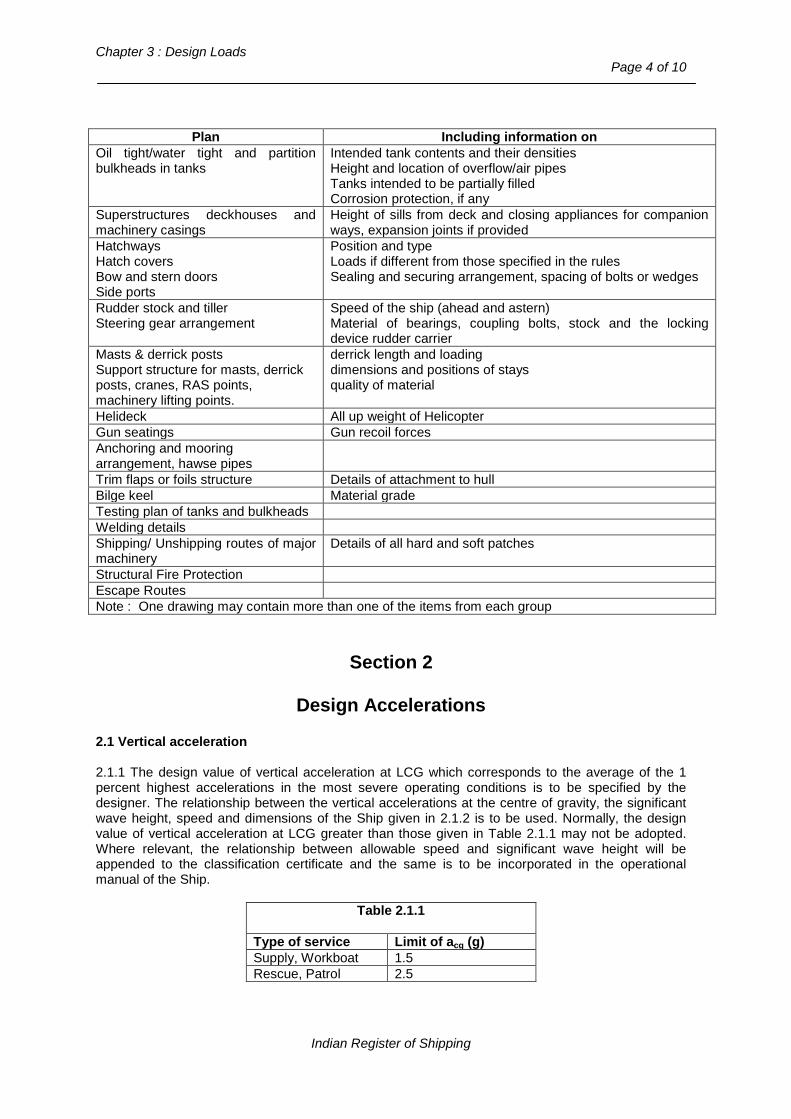
Chapter 3 : Design Loads
Page 4 of 10
Plan Including information on
Oil tight/water tight and partition bulkheads in tanks
Intended tank contents and their densities Height and location of overflow/air pipes Tanks intended to be partially filled Corrosion protection, if any
Superstructures deckhouses and machinery casings
Height of sills from deck and closing appliances for companion ways, expansion joints if provided
Hatchways Hatch covers Bow and stern doors Side ports
Position and type Loads if different from those specified in the rules Sealing and securing arrangement, spacing of bolts or wedges
Rudder stock and tiller Steering gear arrangement
Speed of the ship (ahead and astern) Material of bearings, coupling bolts, stock and the locking device rudder carrier
Masts & derrick posts Support structure for masts, derrick posts, cranes, RAS points, machinery lifting points.
derrick length and loading dimensions and positions of stays quality of material
Helideck All up weight of Helicopter Gun seatings Gun recoil forces Anchoring and mooring arrangement, hawse pipes
Trim flaps or foils structure Details of attachment to hull Bilge keel Material grade Testing plan of tanks and bulkheads Welding details Shipping/ Unshipping routes of major machinery
Details of all hard and soft patches
Structural Fire Protection Escape Routes Note : One drawing may contain more than one of the items from each group
Section 2
Design Accelerations
2.1 Vertical acceleration 2.1.1 The design value of vertical acceleration at LCG which corresponds to the average of the 1 percent highest accelerations in the most severe operating conditions is to be specified by the designer. The relationship between the vertical accelerations at the centre of gravity, the significant wave height, speed and dimensions of the Ship given in 2.1.2 is to be used. Normally, the design value of vertical acceleration at LCG greater than those given in Table 2.1.1 may not be adopted. Where relevant, the relationship between allowable speed and significant wave height will be appended to the classification certificate and the same is to be incorporated in the operational manual of the Ship.
Table 2.1.1 Type of service Limit of acg (g) Supply, Workboat 1.5 Rescue, Patrol 2.5
Indian Register of Shipping
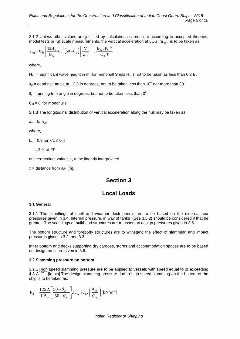
Rules and Regulations for the Construction and Classification of Indian Coast Guard Ships - 2015
Page 5 of 10
2.1.2 Unless other values are justified by calculations carried out according to accepted theories, model tests or full scale measurements, the vertical acceleration at LCG, ‘acg’, is to be taken as:
where, Hs = significant wave height in m, for monohull Ships Hs is not to be taken as less than 0.2 Bw θd = dead rise angle at LCG in degrees, not to be taken less than 10o nor more than 30o. θt = running trim angle in degrees, but not to be taken less than 3o. CH = θt for monohulls 2.1.3 The longitudinal distribution of vertical acceleration along the hull may be taken as: av = kv acg where, kv = 0.8 for x/L ≤ 0.4 = 2.0 at FP at intermediate values kv to be linearly interpolated x = distance from AP [m].
Section 3
Local Loads
3.1 General 3.1.1 The scantlings of shell and weather deck panels are to be based on the external sea pressures given in 3.4. Internal pressure, in way of tanks (See 3.5.2) should be considered if that be greater. The scantlings of bulkhead structures are to based on design pressures given in 3.5. The bottom structure and forebody structures are to withstand the effect of slamming and impact pressures given in 3.2, and 3.3. Inner bottom and decks supporting dry cargoes, stores and accommodation spaces are to be based on design pressure given in 3.6. 3.2 Slamming pressure on bottom 3.2.1 High speed slamming pressure are to be applied to vessels with speed equal to or exceeding 4.8 Δ0.1667 [knots].The design slamming pressure due to high speed slamming on the bottom of the ship is to be taken as:
][kN/mCa
.K..K50
50LB
125P 2
b
cgLA
wsl
−−∆
=d
dl
θθ
[ ]TC
10.B.
LV501
BH12
Cab
5w
2
dw
sHcg
−
θ−
+=
Indian Register of Shipping

Chapter 3 : Design Loads
Page 6 of 10
KA = Area factor as given in Fig.3.2.1 where, AR = reference area = 0.7 L Bw Cb and A = design load area for the element under consideration [m2]. for plating, ‘A’ is not to be greater than 3s2 where s is the spacing of stiffeners. for stiffeners, ‘A’ is to be taken as the stiffener span x spacing.
Fig. 3.2.1 : Area factor for slamming pressure KL = longitudinal distribution factor = 0.5 at A.P. = 0.5 + x/L for x/L ≤ 0.5 = 1.0 for 0.5 ≤ x/L ≤ 0.8 = 3.0 – 2.5 x/L for x/L > 0.8 where x = distance of load point from the A.P. θdl = deadrise angle in degrees at the section under consideration θd = deadrise angle at l.c.g. 3.3 Forebody side and bow impact pressure 3.3.1 Forebody side and bow in the region forward 0.25L from the F.P is to be strengthened for bow impact pressure Pi, is to be taken as: Pi = CL (2.2 + 1.5 tan α) (0.4 V Sin β + 0.6 √L)2 . x/L [kN/m2]
0.35
00.10.20.30.40.50.60.70.80.9
11.1
-0.5 0 0.5 1 1.5 2 2.5 3
Log10(A x 1000 / AR)
KA
Indian Register of Shipping

Rules and Regulations for the Construction and Classification of Indian Coast Guard Ships - 2015
Page 7 of 10
where, V = maximum speed (knots) β = angle made by the tangent to water line with the centre line of the ship at the point under consideration as shown in Fig.3.3.1 CL = 0.0125L, not to be taken more than 1.0 α = angle between the side shell and the vertical as shown in Fig.3.3.1 x = distance from A.P.
Fig.3.3.1 : Bow flare details
3.4 Sea pressure 3.4.1 The pressure ‘p’ acting on the Ship’s side, bottom and weather decks is to be taken as: - For load point below design waterline:
p = 10 ho + (ks – 1.5 ho/T) Cw [kN/m2] - For load point above design waterline:
p = ks (Cw – 0.8 ho) [kN/m2] ho = vertical distance [m] from fully loaded waterline to the loadpoint ks = 7.5 aft of amidships = 5/CB forward of F.P. elsewhere, the value of ks may be obtained by linear interpolation. ‘p’ is not to be taken less than: 10 [kN/m2] for Ship’s sides, 5 [kN/m2] for weather decks For vessels with service restriction notation ‘RS3’ the above values may be reduced to 5 [kN/m2] and 3 [kN/m2] respectively. 3.4.2 For decks forming crown of tanks, loads due to liquids in tanks should be considered as for bulkheads given in 3.5.
α
SEC Y-Y
Y
Y β
F P
Indian Register of Shipping

Chapter 3 : Design Loads
Page 8 of 10
3.4.3 The design pressure on superstructure and bulkheads and deckhouses is not to be taken less than: p = a ks (Cw – 0.8 ho) [kN/m2] where, ho is as defined in 3.4.1 a = factor for location: = 2.0 for lowest tier of unprotected fronts = 1.5 for 2nd tier unprotected fronts = 1.0 for deckhouse sides = 0.8 elsewhere. The design pressure ‘p’, should not be less than: 10 + 0.05L [kN/m2] for lowest tier of unprotected fronts and 5 [kN/m2] elsewhere. For Ships with notation ‘RS3’ the above values may be reduced to 5 [kN/m2] and 3 [kN/m2] respectively. 3.5 Loads on bulkheads 3.5.1 The design pressure for ordinary watertight bulkheads is given by p = 10 h [kN/m2] where, h = the vertical distance from the centre of loading to the top of bulkhead or to the flooded waterline if it is higher. 3.5.2 The design pressure for tank bulkheads are normally to be taken as the greater of: p = (10 + 5 av) hs [kN/m2] p = 6.7 hp [kN/m2] p = 10 hs + po [kN/m2] where, av = vertical acceleration at the load point as given in 2.1.3 hs = vertical distance from the load point to top of tank [m]. hp = vertical distance from the load point to top of air pipe [m]. po = (0.2L + 6) [kN/m2] for L ≤ 90 m = 24 [kN/m2] for L > 90 m. 3.5.3 The design pressure on wash bulkheads is to be taken not less than: p = (4 – 0.005L) lt [kN/m2] for transverse bulkheads
Indian Register of Shipping

Rules and Regulations for the Construction and Classification of Indian Coast Guard Ships - 2015
Page 9 of 10
= (3 – 0.01B) bt [kN/m2] for longitudinal bulkheads where, lt = greater of the distances between the adjacent transverse bulkheads bt = greater of the distances between adjacent longitudinal bulkheads. 3.6 Pressure due to dry cargo, stores and equipment 3.6.1 The design pressure on inner bottom, decks and hatch covers due to dry cargo, stores or equipment is to be taken as the following: p = q (10 + 5 av) [kN/m2] av is as given in 2.1.3 q = deck cargo load [t/m2] = 1 [t/m2] for weather decks and hatchcovers with cargo loading, in general = 1.6 [t/m2] for platform deck in machinery spaces = ρ H [t/m2] for tween decks or inner bottom where, ρ = density of cargo [t/m3] and H is the stowage height [m] q = 0.35 [t/m2] for accommodation decks.
Section 4
Global Loads 4.1 Longitudinal hull girder bending and shear loads 4.1.1 The longitudinal bending and shear strength of the hull girder is to be based on i) the combination of still water and wave bending moments and shear forces as given in
4.1.2, or ii) the dynamic bending moments and shear forces due to slamming effects as given in 4.1.3,
whichever is higher. 4.1.2 The total longitudinal bending moment amidships is given by: ML = Ms + Mw where, Ms = the still water bending moment [kN-m] Mw = -0.11 Cw L2 B (Cb + 0.7) [kN-m] – for sagging condition
Indian Register of Shipping
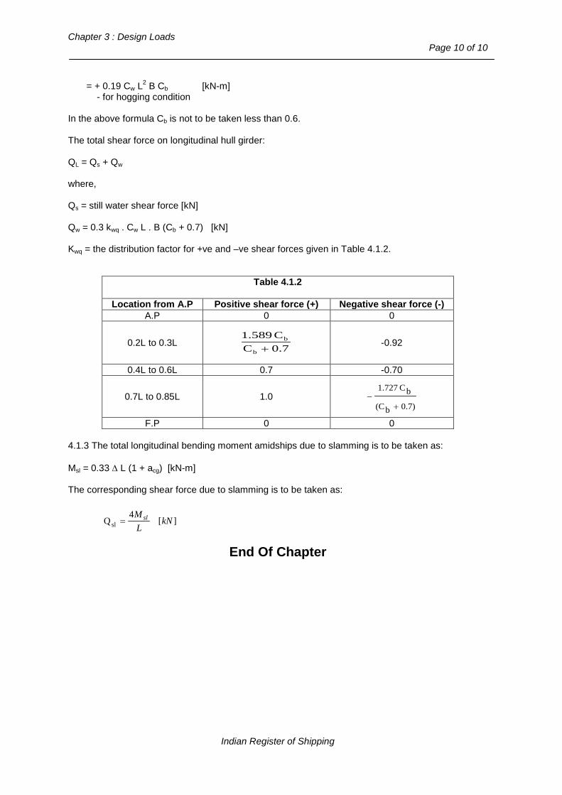
Chapter 3 : Design Loads
Page 10 of 10
= + 0.19 Cw L2 B Cb [kN-m] - for hogging condition In the above formula Cb is not to be taken less than 0.6. The total shear force on longitudinal hull girder: QL = Qs + Qw where, Qs = still water shear force [kN] Qw = 0.3 kwq . Cw L . B (Cb + 0.7) [kN] Kwq = the distribution factor for +ve and –ve shear forces given in Table 4.1.2.
Table 4.1.2 Location from A.P Positive shear force (+) Negative shear force (-)
A.P 0 0
0.2L to 0.3L 0.7CC1.589
b
b
+ -0.92
0.4L to 0.6L 0.7 -0.70
0.7L to 0.85L 1.0 0.7)b(C
bC1.727
+−
F.P 0 0 4.1.3 The total longitudinal bending moment amidships due to slamming is to be taken as: Msl = 0.33 ∆ L (1 + acg) [kN-m] The corresponding shear force due to slamming is to be taken as:
][4
Qsl kNLM sl=
End Of Chapter
Indian Register of Shipping

Rules and Regulations for the Construction and Classification of Indian Coast Guard Ships - 2015
Page 1 of 12
Chapter 4
Stability, Subdivision, Watertight and Weathertight Integrity
Contents Section
1 General, Definitions, Documentation 2 General Stability Requirements 3 Watertight and Weathertight Integrity 4 Subdivision and Arrangement
Section 1
General, Definitions, Documentation
1.1 Scope 1.1.1 All Monohull ships covered by these Rules are to satisfy the Stability requirements in this Chapter and any other additional requirements specified by the Indian Coast Guard. 1.1.2 Other general requirements in respect of subdivision and arrangement, weathertight integrity and loadline are given in Section 3 and 4. 1.2 Definitions 1.2.1 For the purpose of this and other chapters, unless expressly defined otherwise, the following definitions apply. 1.2.2 Down flooding point means any opening, irrespective of size, that would permit passage of water through a water/weathertight structure (e.g. opening windows), but excludes any opening kept closed to an appropriate standard of water/weathertightness at all times other than when required for access or for operation of portable submersible bilge pumps in an emergency (e.g. non-opening windows of similar strength and weathertight integrity to the structure in which they are installed). 1.2.3 Monohull Ship means any Ship which is not a multihull Ship. 1.2.4 Permeability of a space means the percentage of the volume of that space which can be occupied by water. 1.2.5 ∇ = volume of displacement corresponding to the design waterline [m3]. 1.3 Documentation 1.3.1 The following plans or documents are to be submitted for examination or approval of stability, as applicable :
a) Lines plan and offset table.
b) Hydrostatic tables, cross curve tables.
c) Data of all compartment and sub-compartment boundaries.
Indian Register of Shipping

Chapter 4 : Stability, Subdivision, Watertight and Weathertight Integrity
Page 2 of 12
d) Position of all non-watertight and non-weathertight openings.
e) Stability investigation with input and output data including initial loading conditions.
f) Inclining test report.
g) Intact stability report, damage stability computations
h) Damage control plan.
Section 2
General Stability Requirements
2.1 General 2.1.1 A Ship is to have:
a) Buoyancy and stability characteristics adequate for safety where the Ship is operated in the displacement mode both in the intact condition and damaged condition;
b) Stability characteristics and stabilization system adequate for safety when the Ship is operated in the non-displacement mode and during the transient mode;
c) Stability characteristics in the non-displacement and transient modes adequate to transfer
the Ship safely to displacement mode in case of any system malfunction. 2.1.2 Other means of demonstrating compliance with the requirements of any part of this chapter may be accepted, provided that the method chosen can be shown to provide an equivalent/ greater level of safety. Such methods may include:
a) mathematical simulation of dynamic behaviour; b) scale model testing; and c) full-scale trials.
The adequacy of mathematical simulations must first be demonstrated by correlation with full-scale or model tests for the appropriate type of Ship. It may be appropriate to use mathematical simulations to help to identify the more critical scenarios for subsequent physical testing. The model or full-scale tests and/or calculations (as appropriate) shall also include consideration of the following known stability hazards to which high-speed Ship are known to be liable, according to Ship type :
a) directional instability, which is often coupled with roll and pitch instabilities;
b) broaching and bow diving in following seas at speeds near to wave speed, applicable to most types;
c) bow diving of planing monohulls due to dynamic loss of longitudinal stability in relatively
calm seas;
d) reduction in transverse stability with increasing speed of monohulls;
e) porpoising of planing monohulls, being coupled pitch and heave oscillations, which can become violent;
Indian Register of Shipping

Rules and Regulations for the Construction and Classification of Indian Coast Guard Ships - 2015
Page 3 of 12
f) chine tripping, being a phenomenon of planing monohulls occurring when the immersion of a chine generates a strong capsizing moment;
2.1.3 Suitable calculations shall be carried out and/or tests conducted to demonstrate that, when operating within approved operational limitations, the Ship will, after a disturbance causing roll, pitch, heave or heel due to turning or any combination thereof, return to the original attitude. Where calculations are employed, it shall first be shown that they correctly represent dynamic behaviour within the operational limitations of the Ship. 2.2 Buoyant spaces 2.2.1 All Ships are to have a sufficient reserve of buoyancy at the design waterline to meet the intact and damage stability requirements of this Chapter. IRS may require a larger reserve of buoyancy to permit the Ship to operate in any of its intended modes. This reserve of buoyancy is to be calculated by considering:
a) watertight compartments situated below the datum, and;
b) watertight or weathertight compartments situated above the datum. In considering the stability after damage, flooding shall be assumed to occur until limited by
(a) watertight boundaries in the equilibrium condition and
(b) weathertight boundaries in intermediate stages of flooding and within the range of positive righting lever required to satisfy the residual stability requirements.
Where a buoyant space is subjected to increased fluid pressure in the equilibrium position after damage, the boundaries and associated openings and penetrations of that space are to be designed and constructed to prevent the passage of fluid under that pressure. 2.2.2 Arrangements are to be provided for checking the watertight or weathertight integrity of all compartments considered for calculation of reserve buoyancy in paragraph 2.2.1. 2.3 Intact stability in the displacement mode 2.3.1 Subject to 2.3.2 a mono hull Ship are to meet the requirements of Annexure 1 of these rules in all permitted conditions of loading. 2.3.2 Where the characteristics of mono hull Ship are inappropriate for application of Annexure 1 of these rules, alternative criteria equivalent to those stipulated as appropriate to the type of craft and area of operation may be accepted. 2.3.3 The wind speeds, as given in the table below, are to be used for analyzing the stability of the Ship:
Notation Design significant wave height [m] Wind Speed [knots] RS 0 Hs ≥ 4.0 m 60 RS 1 2.5 ≤ Hs < 4.0 m 40 RS 2 0.6 < Hs < 2.5 m 30 RS 3 Hs ≤ 0.6 m 30
2.4 Intact stability in the non-displacement mode 2.4.1 The requirements of this section are to be applied on the assumption that any stabilization systems fitted are fully operational.
Indian Register of Shipping

Chapter 4 : Stability, Subdivision, Watertight and Weathertight Integrity
Page 4 of 12
2.4.2 The roll and the pitch stability on the first and/ or any other Ship of a series should be qualitatively assessed during operational safety trials as required by Annex 3. The result of such trials may indicate the need to impose operational limitations. 2.4.3 Where Ships are fitted with surface piercing structure or appendages, precautions should be taken against dangerous attitudes or inclinations and loss of stability subsequent to a collision with a submerged or floating object. 2.5 Intact stability in the transitional mode 2.5.1 For all weather conditions upto the worst intended conditions, the time to pass from the displacement mode to the non-displacement mode and vice versa should be minimal unless it is demonstrated that no substantial reduction of stability occurs during this transition. 2.6 Buoyancy and stability in the displacement mode following damage 2.6.1 The requirements of this section apply to all permitted conditions of loading 2.6.2 For the purpose of making damage stability calculations the following volume and surface permeabilities are to be assumed in general.
Spaces Permeability Appropriated to cargo or stores 60 Occupied by accommodation 95 Occupied by machinery 85 Intended for liquids 0 or 95* Appropriated for cargo vehicles 90 Voids spaces 95 * Whichever results in the more severe requirements.
2.6.3 Notwithstanding 2.6.2, permeability determined by direct calculation is to be used where a more onerous condition results, and may be used where a less onerous condition results from that provided according to 2.6.2. 2.6.4 IRS may accept the use of low density foam or other media to provide buoyancy in void spaces, provided that there is satisfactory evidence to show that any such proposed medium is the most suitable alternative and is:
a) of closed cell form if foam, or otherwise impervious to water absorption;
b) structurally stable under service conditions;
c) chemically inert in relation to structural materials with which it is in contact or other substances with which the medium is likely to be in contact.
d) properly secured in place and easily removable for inspection of the void spaces.
2.6.5 Void bottom spaces may be fitted within the watertight envelope of the hull without the provision of a bilge system or air pipes, subject to the approval of the Indian Coast Guard, provided that:
a) the structure is capable of withstanding the pressure head after any of the damages required by this section;
b) when carrying out a damage stability calculation in accordance with the requirements of this section, any void space adjacent to the damaged zone shall be included in the calculation and the criteria in 2.6, 3.2 and 4.1 are complied with;
Indian Register of Shipping

Rules and Regulations for the Construction and Classification of Indian Coast Guard Ships - 2015
Page 5 of 12
c) the means by which water which has leaked into the void space is to be removed shall be included in the Ship operating manual.; and
d) adequate ventilation is provided for inspection of the space under consideration as required
by 2.2.2. Void spaces filled with foam or modular buoyancy elements are considered to be void spaces for the purposes of this paragraph, provided such foam or elements fully comply with 2.6.4. 2.6.6 Any damage of a lesser extent than that postulated in 2.6.7 to 2.6.10, as applicable, which would result in a more severe condition, also is also to be investigated. 2.6.7 The following side damages are to be assumed anywhere on the periphery of the Ship:
a) the longitudinal extent of damage is to be 0.75 ∇1/3 , or (3m + 0.225 ∇1/3 ) or 11 m, whichever is the least;
b) the transverse extent of penetration into the Ship is to be 0.2 ∇1/3. However, where the Ship
is fitted with inflated skirts or with non-buoyant side structures, the transverse extent of penetration is to be at least 0.12 ∇1/3 into the main buoyancy hull or tank structure; and
c) the vertical extent of damage is to be taken for the full vertical extent of the Ship.
The damages described in this paragraph shall be assumed to have the shape of a parallelepiped. Applying this to Fig.2.6.7 (a), the inboard face at its mid-length shall be tangential to, or otherwise touching in at least 2 places, the surface corresponding to the specified transverse extent of penetration, as illustrated in Fig.2.6.7 (a). Side damage shall not transversely penetrate a greater distance than the extent of 0.2∇1/3 at the design waterline or the lesser extent given in 2.6.7 (b). (Refer to Fig. 2.6.7 (b)). 2.6.8 Extent of bow and stern damage 2.6.8.1 The following extents of damage are to be applied to bow and stern, as illustrated in Fig.2.6.8:
a) at the fore end, damage to the area defined as Abow, the aft limit of which being a transverse vertical plane, provided that this area need not extend further aft from the forward extremity of the Ship’s watertight envelope than the distance defined in 2.6.7 (a) and
Fig. 2.6.7 (a)
Indian Register of Shipping

Chapter 4 : Stability, Subdivision, Watertight and Weathertight Integrity
Page 6 of 12
b) at the aft end, damage to the area aft of a transverse vertical plane at a distance 0.2∇1/3
forward of the aft extremity of the watertight envelope of the hull. Abow = 0.0035 A m f V, but not les than 0.04A where,
Abow is the plan projected area of Ship energy absorbing structure forward of the transverse plane [m2] (See Fig.2.6.8).
A = total plan projected area for the full length of the Ship [m2]
m = material factor = 0.95/M
M = 1.3 for high-tensile steel
= 1.0 for aluminium alloy
= 0.95 for mild steel
= 0.8 for fibre reinforced plastics.
Where materials are mixed, the material factor is to be taken as a weighted mean, weighted according to the mass of material in the area defined by Abow.
f = framing factor = 0.8 for longitudinal deck and shell stiffening = 0.9 for mixed longitudinal and transverse stiffening = 1.0 for transverse deck and shell stiffening V = 90% of maximum speed [knots].
2.6.8.2 The provisions of 2.6.6 in relation to damage of lesser extent remain applicable to such damage. 2.6.9 Extent of bottom damage 2.6.9.1 This applies to all parts of the hull(s) below the design waterline. Damage shall not be applied at the same time as that defined in 2.6.7 or 2.6.8. 2.6.9.2 Extent The following extent of damage shall be assumed:
Fig. 2.6.7 (b)
Indian Register of Shipping

Rules and Regulations for the Construction and Classification of Indian Coast Guard Ships - 2015
Page 7 of 12
a) the length of damage in the fore-and-aft direction shall be 0.75∇1/3 or (3 m + 0.225 ∇1/3), or
11 m whichever is the least;
b) the athwartships girth of damage shall be 0.2∇1/3 ; and
c) the depth of penetration normal to the shell shall be 0.02∇1/3.
d) the shape of damage shall be assumed to be rectangular in the plane of the shell of the Ship and rectangular in the transverse plane as illustrated in Fig.2.6.9.1.
2.6.10 Following any of the postulated damages detailed in 2.6.6 to 2.6.9, the Ship in still water shall have sufficient buoyancy and positive stability to simultaneously ensure that:
a) for all Ships, after flooding has ceased and state of equilibrium has been reached, the final waterline is below the level of any opening through which further flooding could take place;
b) there is a positive freeboard from the damage waterline to survival Ship embarkation
positions;
c) essential emergency equipment, emergency radios, power supplies and public address systems needed for organising the evacuation remain accessible and operational; and
d) the residual stability of Ship meets the appropriate criteria as laid out in these Rules
according to Table 2.3.2. 2.6.11 Down flooding openings referred to in 2.6.10 a), shall include air pipes, ventilators and other openings which are closed by means of weathertight doors or hatch covers.
Fig. 2.6.9.1
Fig. 2.6.8
Indian Register of Shipping

Chapter 4 : Stability, Subdivision, Watertight and Weathertight Integrity
Page 8 of 12
2.6.12 Angle of inclination from the horizontal of the Ship following damage Following any of the postulated damages detailed in 2.6.6 to 2.6.9, in addition to satisfying the requirements of 2.6.10 , the Ship (in still water) is to have sufficient buoyancy and positive stability to simultaneously ensure that the angle of inclination of the Ship from the horizontal does not normally exceed 15o in any direction. However, where this is clearly impractical, angles of inclination upto 20o immediately after damage but reducing to 15o within 15 min may be permitted provided that efficient non-slip deck surface and suitable holding points, e.g. holes, bars, etc., are provided. 2.7 Inclining and Stability Information 2.7.1 Every Ship on completion of build is to be inclined and the elements of its stability determined. IRS may waive the requirement of inclining experiment, provided basic stability data is available from the inclining test of a sister ship. A weight survey is to be carried out upon completion and the ship is to be inclined whenever, in comparison with the data derived from the sister ship, a deviation from the lightship displacement exceeding 1% for ships of 160 [m] or more in length and 2% for ships of 50 [m] or less in length and as determined by linear interpolation for intermediate lengths or a deviation from the lightship longitudinal centre of gravity exceeding 0.5% of L is found. 2.7.2 When an accurate inclining is not practical the lightship displacement and centre of gravity may be determined by a lightweight survey and accurate calculation, subject to approval by the Indian Coast Guard. On all Ships, where an accurate inclining experiment is impractical owing to the height of the center of gravity (VCG or KG) being less than one third of the transverse metacentric height (GMT), IRS may accept estimation of KG by detailed calculation in place of an inclining experiment. In such cases, a displacement check is to be undertaken to confirm the calculated lightship characteristics, including LCG, which may be accepted if the measured lightship displacement and LCG are respectively within 2% and 1% L relative to the estimate. 2.7.3 The Master is to be supplied by the Shipbuilder with reliable information relating to the stability of the Ship which has been approved by IRS incorporating such additions and amendments as IRS in any particular case may have required. 2.7.4 Where any alterations are made to a Ship so as materially to affect the stability information supplied to the master, amended stability information is to be provided. If necessary, the Ship is to be re-inclined. 2.7.5 A report of each inclining or lightweight survey carried out in accordance with this Chapter and of the calculation therefrom of the lightship condition particulars is to be submitted to IRS for approval, together with a copy for their retention. The approved report is to be placed on board the Ship by the owner in the custody of the master and is to incorporate such additions and amendments as IRS may in any particular case require. The amended lightship condition particulars so obtained from time to time is to be used by the master in substitution for such previously approved particulars when calculating the Ship’s stability. 2.7.6 The above mentioned stability information demonstrating compliance with this chapter is to be furnished in the form of a stability information book to be kept on board the Ship at all times in the custody of the master. The information is to include particulars appropriate to the Ship and must reflect the Ship’s loading conditions and mode of operation. Any enclosed superstructures or deckhouses included in the cross curves of stability and the critical downflooding points and angles are to be identified. 2.7.7 Every Ship is to have scales of draughts marked permanently and clearly at the bow and stern. Accuracy of the draught marks should be demonstrated to IRS prior to the inclining experiment. In the case where the draught marks are not located where they are easily readable, or operational constraints for a particular trade make it difficult to read the draught marks, then the Ship is also be
Indian Register of Shipping
Rules and Regulations for the Construction and Classification of Indian Coast Guard Ships - 2015
Page 9 of 12
fitted with a reliable draught indicating system by which the bow and stern draughts can be determined. 2.7.8 At periodical intervals, not exceeding five years, a lightweight survey is to be carried out on all Ships to verify any changes in lightweight displacement and longitudinal centre of gravity. The Ship is to be re-inclined whenever, in comparison with the approved stability information, a deviation from the lightweight displacement exceeding 2% or a deviation of the longitudinal centre of gravity exceeding 1% of L is found or anticipated. 2.8 Loading and stability assessment On completion of loading of the Ship and prior to its departure on a voyage, the Ship’s trim and stability is to be determined and recorded by the master in order to ascertain that the Ship is in compliance with stability criteria of the relevant requirements. IRS may accept the use of an electronic loading and stability computer or equivalent means for this purpose. 2.9 Damage control plan 2.9.1 A damage control plan is to be permanently exhibited or readily available on the navigating bridge and is to include inboard profile, plan views of each deck and transverse section necessary to show the following:
a) the watertight boundaries of the ship,
b) the locations and arrangements of cross flooding systems if any,
c) the locations of all internal watertight closing appliances and their local and remote controls, position indicators and alarms. Information regarding the usage of doors such as ‘open while at sea’, ‘not used while at sea’ etc. should be clearly indicated,
d) the locations of all doors on the shell of the Ship, position indicators, leakage detectors and
surveillance devices,
e) the locations of all weathertight closing appliances in local subdivision boundaries above the bulkhead deck and on the lowest exposed weather decks, their controls and position indicators if any,
f) the locations of all bilge and ballast pumps, their control positions and associated valves.
2.9.2 The above information is to be repeated in a damage control booklet to be kept on board the Ship. The damage control booklet is to also include instructions for controlling the effects of damage in detail.
Section 3
Watertight and Weathertight Integrity
3.1 Openings in watertight divisions 3.1.1 The number of openings in watertight bulkheads are to be kept at the minimum compatible with the design and proper working of the Ship and all such doors are to be closed prior to departure of the Ship from the berth. 3.1.2 Doors in watertight bulkheads may be hinged or sliding. They are to be shown by suitable testing to be capable of maintaining the watertight integrity of the bulkhead. Such testing is to be carried out for both sides of the door and shall apply a pressure head 10% greater than that determined from the minimum permissible height of a down flooding opening. (Refer to 2.6.10)
Indian Register of Shipping

Chapter 4 : Stability, Subdivision, Watertight and Weathertight Integrity
Page 10 of 12
Testing may be carried out either before or after the door is fitted into the Ship but, where shore testing is adopted, satisfactory installation in the Ship is to be verified by inspection and hose testing. 3.1.3 Type approval may be accepted in lieu of testing individual doors, provided the approval process includes pressure testing to a head equal to, or greater than, the required head (Refer to 3.1.2). 3.1.4 All watertight doors are to be capable of being operated when the Ship is inclined upto 15°, and are to be fitted with means of indication in the operating compartment showing whether they are open or closed. All such doors are to be capable of being opened and closed locally from each side of the bulkhead. 3.1.5 Watertight doors are to remain closed when the Ship is at sea, except that they may be opened for access. A notice is to be attached to each door to the effect that it is not to be left open. 3.1.6 Watertight doors are to be capable of being closed by remote control from the operating compartment in not less than 20s and not more than 40s, and are to be provided with an audible alarm, distinct from other alarms in the area, which will sound for at least 5s but no more than 10s before the doors begin to move whenever the door is closed remotely by power and continue sounding until the door is completely closed. The power, control and indicators are to be operable in the event of main power failure, as required by regulation II-1/15.7.3 of SOLAS. In accommodation areas and areas where the ambient noise exceeds 85 dB(A) the audible alarm is to be supplemented by an intermittent visual signal at the door. Where such doors are essential for the safe work of the Ship, hinged watertight doors having only local control may be accepted for areas to which crew only have access, provided they are fitted with remote indicators as required by 3.1.4. 3.1.7 Where pipes, scuppers, electric cables, etc. are carried through watertight divisions, the arrangements for creating a watertight penetration shall be of a type which has been prototype tested under hydrostatic pressure equal to or greater than that required to be withstood for the actual location in the Ship in which they are to be installed. The test pressure shall be maintained for at least 30 min and there must be no leakage through the penetration arrangement during this period. The test pressure head shall be 10% greater than that determined from the minimum permissible height of a down flooding opening. Watertight bulkhead penetrations which are effected by continuous welding do not require prototype testing. 3.1.8 Where a ventilation trunk forms part of a watertight boundary, the trunk shall be capable of withstanding the water pressure that may be present, taking into account the maximum inclination angle allowable during all stages of flooding. 3.2 Indicators and surveillance 3.2.1 Indicators Indicators are to be provided in the operating compartment for all shell doors, loading doors and other closing appliances which, if left open or not properly secured, could lead to major flooding in the intact and damage conditions. The indicator system is to be designed on the fail-safe principle and is to show by visual alarms if the door is not fully closed or if any of the securing arrangements are not in place and fully locked and by audible alarms if such door or closing appliance becomes open or the securing arrangements become unsecured. The indicator panel in the operating compartment is to be equipped with a mode-selection function 'harbour / sea voyage' so arranged that an audible alarm is given in the operating compartment if the Ship leaves harbour with the bow doors, inner doors, stern ramp or any other side shell doors not closed or any closing device not in the correct position. The power supply for the indicator system is to be independent of the power supply for operating and securing the doors.
Indian Register of Shipping

Rules and Regulations for the Construction and Classification of Indian Coast Guard Ships - 2015
Page 11 of 12
3.2.2 Television surveillance Television surveillance and a water leakage detection system is to be arranged to provide an indication to the operating compartment and to the engine control station of any leakage through inner and outer bow doors, stern doors or any other shell doors which could lead to major flooding. 3.3 Integrity of superstructure 3.3.1 Where entry of water into structures above the datum would significantly influence the stability and buoyancy of the Ship, such structures are to be
a) of adequate strength to maintain the weathertight integrity and fitted with weathertight closing appliances; or
b) provided with adequate drainage arrangements; or c) an equivalent combination of both measures.
3.3.2 Weather tight superstructures and deckhouses located above the datum shall, in the outside boundaries, have means of closing openings with sufficient strength such as to maintain weathertight integrity in all damage conditions where the space in question is not damaged. Furthermore, the means of closing shall be such as to maintain weathertight integrity in all operational conditions.
Section 4
Subdivision and Arrangement
4.1 Applicability 4.1.1 The requirements in this section apply to all Ships. 4.2 Transverse bulkheads 4.2.1 The following transverse watertight bulkheads are to be fitted in all Ships: • A collision bulkhead • An aftpeak bulkhead • A bulkhead at each end of the machinery space. Additional bulkheads, as necessary to satisfy any applicable Damage Stability requirements are to be fitted at suitable locations. 4.2.2 The watertight bulkheads are in general to extend to the freeboard deck. The afterpeak bulkhead may terminate at the fore deck above the loadwater line provided that the deck is made watertight to the stern or to a watertight transom floor. 4.2.3 The collision bulkhead is normally to extend to the uppermost continuous deck or, in the case of ships with a long superstructure that includes a forecastle, to the superstructure deck. 4.2.4 For Ships with two continuous decks and a large freeboard to the uppermost deck with the second deck above design waterline, all bulkheads except the collision bulkhead may be terminated at the second deck. 4.2.5 The distance xc from the forward perpendicular to the collision bulkhead is to be between the following limits:
xc (minimum) = 0.05L [m] xc (maximum) = 3.0 + 0.05L [m]
Indian Register of Shipping

Chapter 4 : Stability, Subdivision, Watertight and Weathertight Integrity
Page 12 of 12
However, positioning of collision bulkhead aft of the above limits may be considered if calculation showing that with the Ship loaded to design waterline, flooding of the space forward of the collision bulkhead will not result in any part of the freeboard deck becoming submerged or result in any unacceptable loss of stability. 4.2.6 Any recesses or steps in collision bulkheads are to fall within the limits of bulkhead positions given in 4.2.5. 4.3 Cofferdams 4.3.1 Fuel oil, lubricating oil and freshwater tanks are to be separated from each other by cofferdams. However, cofferdams need not be fitted between fuel oil and lubricating oil tanks provided that the common boundaries have full penetration welds and the head of fuel oil is generally not in excess of that in the adjacent lubricating oil tanks. 4.4 Shell doors 4.4.1 The scantlings and arrangements of any side shell doors, stern or bow doors are to be as given in Part 3, Chapter 12 of the IRS Rules and Regulations for the Construction and Classification of Steel Ships; with appropriate value of design loads given in Chapter 3 of these rules. In the case of aluminium doors, appropriate material factor is to be used in the formulations. 4.5 Testing of hull structure 4.5.1 In general the testing of tanks, watertight bulkheads, weathertight hatchcovers and closing appliances is to be carried out in accordance with the requirements given in Part 3, Chapter 18, Section 3 of the IRS Rules and Regulations for the Construction and Classification of Steel Ships. The references to 'freeboard deck' in the above rules are to be taken as references to 'Datum'. 4.6 Ventilation, Air Pipes and Discharges 4.6.1 The scantlings and arrangements for ventilation, air pipes and discharges are to be as per Part 3, Chapter 13 of the IRS Rules and Regulations for the Construction and Classification of Steel Ships. 4.7 Bulwarks and Guard Rails 4.7.1 The arrangement of bulwarks and guard rails is to be as per Part 3, Chapter 11, Section 5 of the IRS Rules and Regulations for the Construction and Classification of Steel Ships. 4.8 Other Openings and Weathertight Closing Appliances 4.8.1 The requirements of Part 3, Chapter 12 of the IRS Rules and Regulations for the Construction and Classification of Steel ships are to be complied with including door sill heights, coaming heights of hatches etc
End of Chapter
Indian Register of Shipping

Rules and Regulations for the Construction and Classification of Indian Coast Guard Ships - 2015
Page 1 of 50
Chapter 5
Structures : Steel and Aluminium
Contents Section
1 Principles of Scantlings and Structural Details
2 Hull Girder Strength
3 Plating
4 Secondary Stiffeners
5 Primary Girders and Pillars
6 Welding
7 8
Direct Strength Analysis Helicopter Decks
9 Vehicle Decks
Section 1
Principles of Scantlings and Structural Details
1.1 Application 1.1.1 Scantlings of various platings, stiffeners and girders satisfying the local strength requirements are to be determined in accordance with the general principles given in the chapter. Scantlings of hull members contributing to the longitudinal strength are also to comply with the requirements of Section 2. 1.1.2 The design values of loads to be considered are given in Chapter 3 and further detailed reference of the applicable loads is given in individual sections of this chapter. 1.1.3 Scantlings of hull members subjected to compressive stresses are also to comply with the requirements to resist buckling given in ‘Rules and Regulations for the Construction and Classification of Steel Ships’ Part 3, Chapter 3, Section 6. 1.2 Symbols
p = design pressure [kN/m2] as per 1.1.2. s = spacing of stiffeners [m], measured along the plating l = span of the stiffener [m], in accordance with 1.4 S = span of girder [m] or primary supporting member, in accordance with 1.4. b = mean breadth [m] of the load area supported by the girder σa = allowable bending stress [N/mm2], as given in relevant sections σy = minimum yield stress of material [N/mm2] may be taken as 235 [N/mm2] for normal strength steel. For aluminium alloys the guaranteed minimum 0.2% proof stress [N/mm2] of the alloy in
Indian Register of Shipping

Chapter 5 : Structures : Steel and Aluminium
Page 2 of 50
welded condition or 70% of the ultimate strength in the welded condition, whichever is lesser, is to be used. k = material factor given in Chapter 2, Cl. 2.2 and 3.2. E = modulus of elasticity: = 2.06 x 10⁵ [N/mm2] for steel and 0.7 x 10⁵ [N/mm2] for aluminium alloy. L= Length of ship as defined in 2.6.18 of Chapter 1.
1.3 Frame spacing 1.3.1 The standard frame spacing ‘sr’ may be taken as 480 + 2L [mm]. 1.3.2 Where the actual frame spacing differs from the standard frame spacing given in 1.3.1 the minimum thickness requirement for various structural members is to be corrected in direct proportion. 1.4 Stiffeners and girders 1.4.1 For stiffeners, the span ‘l’ [m] is to be taken as the length of the stiffener between the two supporting members less the depth of stiffener on crossing panel if any. Where brackets larger than those required in 1.5.1 are fitted, the span may be determined as shown in Fig.1.4.1. For curved stiffeners, ‘l’ may be based on the chord length. 1.4.2 For girders, the span ‘S’ [m] is to be taken as the length of the girder between the two supporting members, less the web height of in-plane girder if any and the correction for bracket ‘bc’, as shown in Fig.1.4.2. 1.4.3 The area of the attached plating to be used in the calculation of sectional properties of the stiffeners and girders, is to be taken as the cross sectional area within the effective width of the attached plating. 1.4.4 The effective width of plating attached to a stiffener may be taken as the mean of spacings on either side of the stiffener. 1.4.5 The effective width of plating attached to a girder, ‘be’ is to be taken as per the following:
be = c . b where, c = c1, for girders with uniformly distributed loads or with six or more evenly spaced point loads = c2, for girders with three or less evenly spaced point loads.
Table 1.4.5 : Values of “c” a/b 0.5 1.0 2.0 3.0 4.0 5.0 6.0 ≥ 7.0 c1 0.19 0.38 0.67 0.84 0.93 0.97 0.99 1.00 c2 0.11 0.22 0.40 0.52 0.65 0.73 0.78 0.80
For intermediate values of a/b and number of point loads, values of ‘c’ may be obtained by interpolation. a = span of the girder, for simply supported girders [m] = 60 per cent of span of the girder, for girders fixed at both ends [m].
Indian Register of Shipping
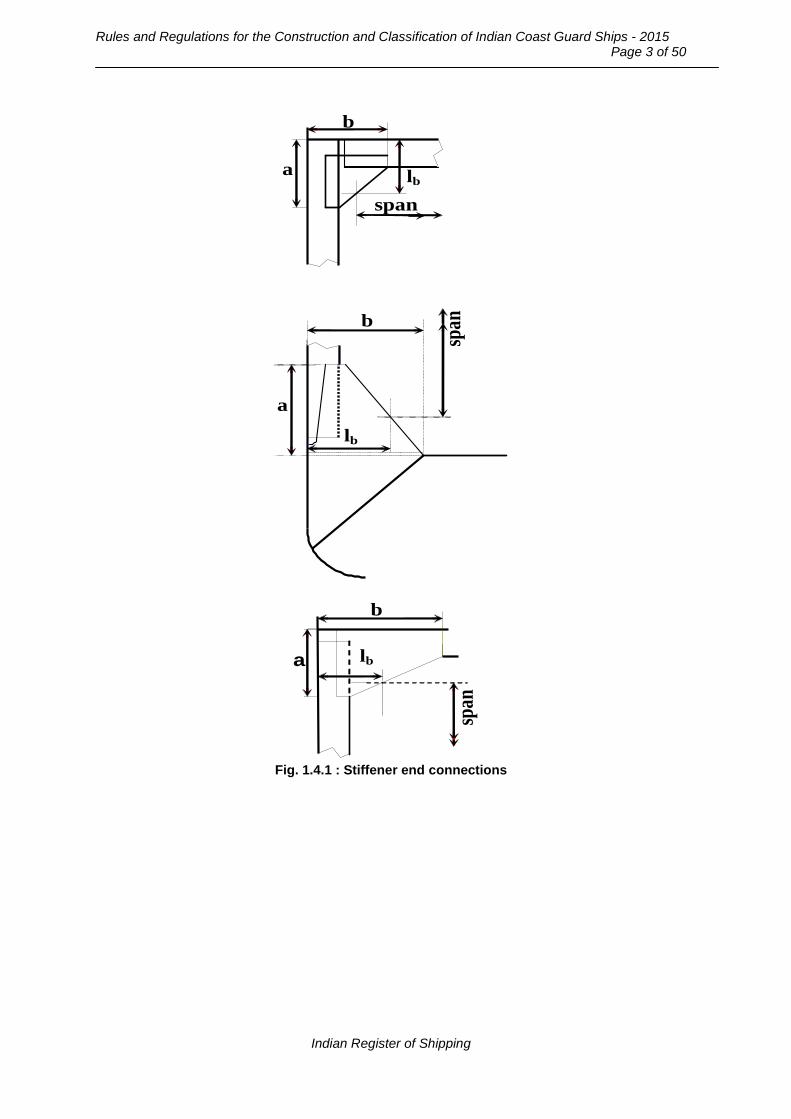
Rules and Regulations for the Construction and Classification of Indian Coast Guard Ships - 2015
Page 3 of 50
b
a
span
b
a
span
a
b
lb
span
lb
lb
Fig. 1.4.1 : Stiffener end connections
Indian Register of Shipping

Chapter 5 : Structures : Steel and Aluminium
Page 4 of 50
a
bb
bc
hw
span
a
span
a
span
bc = bb (1-hw/a)
bc
bb
bc
bb
hw
hw
Fig. 1.4.2 : Girder end details 1.4.6 In case of girders on corrugated bulkheads which run across the corrugations, the effective width of attached plating is to be taken as 10% of that obtained from 1.4.5. 1.4.7 The effective cross sectional area of the attached plating is not to be less than that of the face plate. 1.4.8 The effective cross sectional area of the girder web is to be taken as:
Aw = 0.01 hn tw [cm2] where, hn = net girder height [mm], after deduction of cutouts at the section under consideration. Where an opening is located at a distance less than hw/3 from the cross section under consideration, hn is to be taken as the smaller of the net height and the distance through the opening (hn1 + hn2) (See Fig. 1.4.8).
Indian Register of Shipping

Rules and Regulations for the Construction and Classification of Indian Coast Guard Ships - 2015
Page 5 of 50
hn1
hn
hw
hn2 hn
tw
tw
a
ls
<hw/3
θ
Fig. 1.4.8 : Effective web area of girders Where the girder flange is at angle θ to the length of the girder, Aw may be taken as:
Aw = 0.01 hn tw + 1.3 a Sin 2θ Sin θ [cm2] where, a = area of flange [cm2] The requirement of effective web area of various girders are given in the 5.1. 1.4.9 The thickness of the girder web tw is not to be less than:
[mm]65wS
wt =
where, Sw = web depth or spacing [mm], of the first web stiffener parallel to the face plate. The web stiffeners may be flat bars of same thickness as that of the web and 1/10 of the height of girder, in depth. 1.4.10 Where openings are cut in the girder web, they are to be away from the girder ends and scallops for stiffeners; with their centre location as near to the neutral axis of the girder as practicable. Openings of depth exceeding 25% of the girder depth or 300 [mm] and of length exceeding the depth of the girder or 60% of the secondary stiffener spacing, are to be reinforced all around at the edge; or alternatively by providing horizontal and vertical stiffeners. 1.4.11 Girders are to be provided with adequate lateral stability by tripping brackets fitted generally at every alternate stiffener in case of asymmetrical section or at every fourth stiffener in case of symmetrical section. Tripping brackets are also to be fitted at the toes of end brackets and in way of concentrated loads such as heels of pillars or cross ties. Where the width of face plate on one side of the web exceeds 15 tf, the tripping brackets are to be connected to the face plate. The tripping brackets are to be adequately dimensioned at base and are to have a smooth transition to the adjoining stiffeners. The free edge of the tripping bracket is to be stiffened if it’s length exceeds 60 t [mm]. Additional stiffeners are to be fitted parallel to the free edge to ensure that the arm length of an unstiffened triangular end panel does not exceed 100 t [mm].
Indian Register of Shipping

Chapter 5 : Structures : Steel and Aluminium
Page 6 of 50
1.5 End attachments a) End attachments of stiffeners 1.5.1 Scantlings of brackets fitted on stiffeners not participating in the longitudinal strength are not to be less than the following: - The arm lengths, ‘a’ and ‘b’ (See Fig.1.4.1) are to be such that:
i) a, b ≥ 0.8 lb
and
ii) a + b ≥ 2.0 lb where,
lb = 24 √Z + 75 [mm] - Thickness of unflanged bracket is to be not less than:
t = (4.0 + 0.3 √Z ) √(kb / ks) [mm] - Thickness of flanged bracket is to be not less than:
t = (3.0 + 0.25 √Z ) √(kb / ks) [mm]
but need not be taken greater than 13.5 [mm]. - Width of flange, w ≥ 40 + Z/25 [mm], but not to be less than 50 [mm].
where,
Z is the section modulus [cm3], of the smaller stiffener, being connected.
kb, ks are the material factors for the bracket and the stiffener, respectively. b) End attachments of girders 1.5.2 The end attachments and supporting structure of the girders are to provide adequate resistance against rotation and displacement of the joint and effective distribution of the load from the member. Supporting members to which the girders are being connected, may require additional strengthening to provide adequate stiffness to resist rotation of the joint. Where the end attachment provides only a low degree of restraint against rotation, the girder is generally to be extended beyond the point of support by at least two frame spaces before being gradually tapered. Connections between girders forming a ring system are to be such as to minimize stress concentrations at the junctions. Integral brackets are generally to be radiused or well rounded at the toes. Where the face plate of the girder is not continuous over the bracket, the free edge of the bracket is to be stiffened and the face plate of the girder is to be extended well beyond the toe of the bracket. 1.5.3 The thickness ‘t’ of brackets on girder is not to be less than that of the girder web. The arm length ‘a’ including the depth of girder is not to be less than: A = 83 √(Z/t) [mm];
Indian Register of Shipping

Rules and Regulations for the Construction and Classification of Indian Coast Guard Ships - 2015
Page 7 of 50
where, Z = the section modulus [cm3], of the girder to which the bracket is connected. The cross sectional area ‘Af’ of the face plate on the girder bracket is not to be less than:
Af = 0.001 lf t [cm2] where, lf is the length [mm], of the free edge of the bracket. Additional stiffeners parallel to the bracket face plate are to be fitted on webs of large brackets. The arm length of an unstiffened triangular end panel of bracket is generally not to exceed 100 t [mm]. 1.6 Corrosion protection 1.6.1 The scantlings determined from the formulae provided in the Rules assume that the materials used are selected, manufactured and protected in such a way that there is negligible loss in strength by corrosion. Where the materials are not adequately protected against corrosion, by painting or other approved means, the scantlings may require to be further considered. 1.6.2 Where bimetallic connections are made, involving dissimilar metals, measures are to be incorporated to preclude galvanic corrosion. In order to prevent galvanic corrosion, special attention is to be given to the penetrations of and connections to the hull, bulkheads and decks by piping and equipment where dissimilar materials are involved. The design is to ensure that the location of all bimetallic connections allows for regular inspection and maintenance of the joints and penetrations during service. 1.6.3 The hull, deck and all surfaces exposed to the marine environment are to be suitably protected against corrosion. This may be by coating and/or by a system of cathodic protection in accordance with the requirements detailed below. 1.6.4 In case of steel Ships, all internal spaces except the integral fuel tanks are to be suitably protected against corrosion. In case of aluminium Ships the internal spaces need not in general be coated provided they are built of suitable grades as per Chapter 3. 1.6.5 Paints or other coatings are to be suitable for the intended purpose in the locations where they are to be used and are generally to be hard coatings. Coatings are to be of adequate film thickness, applied in accordance with the paint manufacturer’s specification and are to be compatible with any previously applied primer. Primers used are to be of a type approved in accordance with Part 3, Chapter 2 of the ‘Rules and Regulations for the Construction and Classification of Steel Ships’. Paints, varnishes and similar preparations having a nitro-cellulous or other highly flammable base are not to be used in accommodation or machinery spaces. In case of aluminium ships, paints containing lead, mercury or copper are not to be used. 1.6.6 All steel structures are to be suitably cleaned and cleared of millscale before the application of any coating. It is recommended that blast cleaning, or other equally effective means, be employed for this purpose. All aluminium structures are to be suitably cleaned, cleared of oxide and degreased before the application of any coating. 1.6.7 Where an impressed current cathodic protection system is fitted, plans showing the proposed layout of anodes, reference cells, wiring diagram and the means of bonding-in of the rudder and propeller are to be submitted.
Indian Register of Shipping
Chapter 5 : Structures : Steel and Aluminium
Page 8 of 50
The arrangements for glands, where cables pass through the shell, are to include a small cofferdam. Cables to anodes are not to be led through tanks containing low flash point oils. 1.6.8 Anodes to be used for protection of ballast spaces are to be of an approved type and fitted in accordance with the requirements of Part 3, Chapter 2 of the ‘Rules and Regulations for the Construction and Classification of Steel Ships’. In case of aluminium Ships, particular attention is to be paid to the electric potential of aluminium alloys used in the construction during selection of the anodes, anodes containing mercury however, are not to be used. 1.6.9 Where plated decks are sheathed with wood, the sheathing is to be efficiently attached to the deck, caulked and sealed, to the satisfaction of the Surveyor in accordance with the approved drawings. Deck coverings within accommodation spaces, control stations, stairways and corridors are to be of a type, which will not readily ignite where used on decks.
Section 2
Hull Girder Strength
2.1 General 2.1.1 Scantlings of hull members contributing to longitudinal strength are to comply with the requirements given in the section. These members are also to comply with the requirement of buckling strength as mentioned in 1.1.3. 2.1.2 In general, the longitudinal strength is to be checked for all Ships where L/D > 12 and/or L > 50 m. For other vessels longitudinal strength calculations may be required based on the form, construction arrangement and loading. 2.1.3 For new designs of large and structurally complicated Ship the rule scantling calculations are to be complemented by a direct calculation using 3D finite element analysis. The design loads are to be based on model tests or full scale measurements where available or required. 2.2 Hull section modulus 2.2.1 The required section modulus of the hull is given by:
][cm1000xM
Z 3
σ=
where, M is the longitudinal bending moment, which is greater of: a) Bending Moment due to slamming Msl given in Chapter 3, Section 4.1.3 and b) Total Bending Moment Mt = (Ms + Mw) given in Chapter 3, Section 4.1.2. σ = 175/k {N/mm2]. 2.3 Openings in longitudinal strength members 2.3.1 The effective sectional area of continuous longitudinal members considered in the calculation of section modulus should be the net area after deduction of openings. Shadow areas representing
Indian Register of Shipping

Rules and Regulations for the Construction and Classification of Indian Coast Guard Ships - 2015
Page 9 of 50
the imaginary longitudinal extension of an opening is to be deducted by drawing two tangent lines with an opening angle of 30o as shown in Fig.2.3.1. 2.3.2 The keel plate is normally not to have any openings. In the bilge plate within 0.6L amidships openings are to be avoided as far as practicable. Openings in strength deck are to be kept well clear of Ship’s side and hatch corners. 2.3.3 Circular openings with diameter equal to or more than 0.325 m are to have edge reinforcement. Elliptical openings are to have their major area in the fore and aft direction. Where the ratio of the major axis to the minor axis is less than 2 the openings are to have edge reinforcement.
b1
b1
b1
30o
Fig. 2.3.1 : Shadow areas 2.3.4 Rectangular openings are to have their corners well rounded. Where corners are of circular shape, the radius is not to be less than 20 percent of the breadth of the opening and the edges are to be reinforced.
Section 3
Plating
3.1 General 3.1.1 The thickness ‘t’ of plating subjected to lateral pressure given by:
where, ‘s’ is the frame spacing [mm] p = lateral pressure [kN/m2] σa = permissible stress [N/mm2] given in Table 3.1.1
[mm]psf.f0.0158
ta
ra
σ=
Indian Register of Shipping
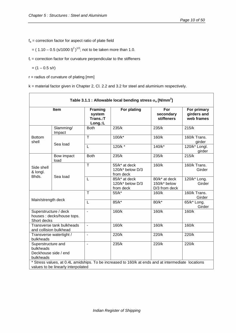
Chapter 5 : Structures : Steel and Aluminium
Page 10 of 50
fa = correction factor for aspect ratio of plate field = ( 1.10 – 0.5 (s/1000 l)2 )1/2; not to be taken more than 1.0. fr = correction factor for curvature perpendicular to the stiffeners = (1 – 0.5 s/r) r = radius of curvature of plating [mm] k = material factor given in Chapter 2, Cl. 2.2 and 3.2 for steel and aluminium respectively.
Table 3.1.1 : Allowable local bending stress σa [N/mm2]
Item Framing
system Trans.:T Long.:L
For plating For secondary stiffeners
For primary girders and web frames
Bottom shell
Slamming/ Impact
Both 235/k 235/k 215/k
Sea load
T 100/k* 160/k 160/k Trans. girder
L 120/k * 140/k* 120/k* Longl. girder
Side shell & longl. Bhds.
Bow impact load
Both 235/k 235/k 215/k
Sea load
T 55/k* at deck 120/k* below D/3 from deck
160/k 160/k Trans. Girder
L 85/k* at deck 120/k* below D/3 from deck
80/k* at deck 150/k* below D/3 from deck
120/k* Long. Girder
Main/strength deck
T 55/k* 160/k 160/k Trans. Girder
L 85/k* 80/k* 65/k* Long. Girder
Superstructure / deck houses : decks/house tops. Short decks
- 160/k 160/k 160/k
Transverse tank bulkheads and collision bulkhead
- 160/k 160/k 160/k
Transverse watertight / bulkheads
- 220/k 220/k 220/k
Superstructure and bulkheads Deckhouse side / end bulkheads
- 235/k 220/k 220/k
* Stress values, at 0.4L amidships. To be increased to 160/k at ends and at intermediate locations values to be linearly interpolated
Indian Register of Shipping
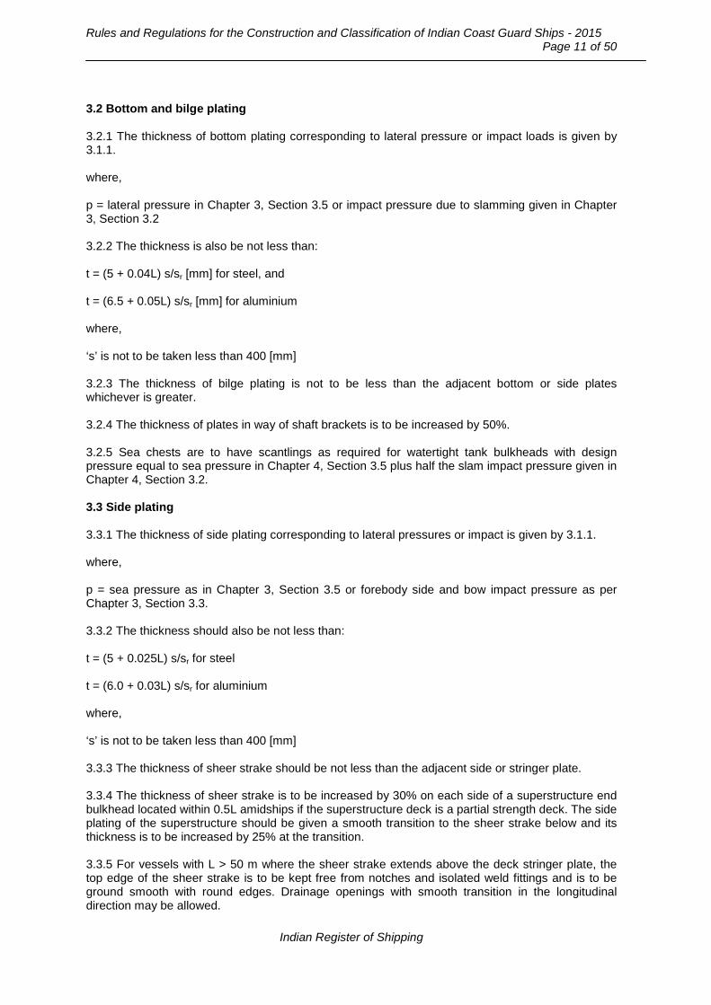
Rules and Regulations for the Construction and Classification of Indian Coast Guard Ships - 2015
Page 11 of 50
3.2 Bottom and bilge plating 3.2.1 The thickness of bottom plating corresponding to lateral pressure or impact loads is given by 3.1.1. where, p = lateral pressure in Chapter 3, Section 3.5 or impact pressure due to slamming given in Chapter 3, Section 3.2 3.2.2 The thickness is also be not less than: t = (5 + 0.04L) s/sr [mm] for steel, and t = (6.5 + 0.05L) s/sr [mm] for aluminium where, ‘s’ is not to be taken less than 400 [mm] 3.2.3 The thickness of bilge plating is not to be less than the adjacent bottom or side plates whichever is greater. 3.2.4 The thickness of plates in way of shaft brackets is to be increased by 50%. 3.2.5 Sea chests are to have scantlings as required for watertight tank bulkheads with design pressure equal to sea pressure in Chapter 4, Section 3.5 plus half the slam impact pressure given in Chapter 4, Section 3.2. 3.3 Side plating 3.3.1 The thickness of side plating corresponding to lateral pressures or impact is given by 3.1.1. where, p = sea pressure as in Chapter 3, Section 3.5 or forebody side and bow impact pressure as per Chapter 3, Section 3.3. 3.3.2 The thickness should also be not less than: t = (5 + 0.025L) s/sr for steel t = (6.0 + 0.03L) s/sr for aluminium where, ‘s’ is not to be taken less than 400 [mm] 3.3.3 The thickness of sheer strake should be not less than the adjacent side or stringer plate. 3.3.4 The thickness of sheer strake is to be increased by 30% on each side of a superstructure end bulkhead located within 0.5L amidships if the superstructure deck is a partial strength deck. The side plating of the superstructure should be given a smooth transition to the sheer strake below and its thickness is to be increased by 25% at the transition. 3.3.5 For vessels with L > 50 m where the sheer strake extends above the deck stringer plate, the top edge of the sheer strake is to be kept free from notches and isolated weld fittings and is to be ground smooth with round edges. Drainage openings with smooth transition in the longitudinal direction may be allowed.
Indian Register of Shipping

Chapter 5 : Structures : Steel and Aluminium
Page 12 of 50
3.4 Deck plating 3.4.1 The thickness of deck plating to be designed to withstand lateral pressure as given by 3.1.1. where, p = weather load given in Chapter 3, Section 3.5.1 or other loads as applicable 3.4.2 The thickness of deck plating is also be not less than the following: a) For strength deck
t = (5 + 0.02L) s/sr [mm] for steel, and t = (6 + 0.03L) s/sr [mm] for aluminium.
where, ‘s’ is not to be taken less than 400 [mm] b) For other decks t = (4.5 + 0.01L) s/sr [mm] for steel t = (6 + 0.01L) s/sr for aluminium. where, ‘s’ is not to be taken less than 400 [mm] 3.4.3 Adequate transverse buckling strength is to be provided for deck plating by increased thickness or by providing intercoastal transverse stiffeners. 3.4.4 Where corners of openings in the strength deck are not of streamlined shape, inserts plates are to be fitted at the corners. The insert plates are to be 25 percent thicker than the deck plating outside the line of openings and are to extend as shown in Fig.3.4.4.
x1 x2
y 1
y 2 r
x1,x2 > 1.5r
y1 > 2r
y2 > r
'r' as per 2.3.4
Fig.3.4.4 : Extent of insert plate
Indian Register of Shipping
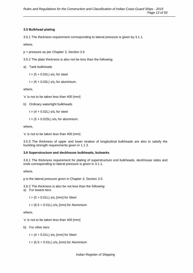
Rules and Regulations for the Construction and Classification of Indian Coast Guard Ships - 2015
Page 13 of 50
3.5 Bulkhead plating 3.5.1 The thickness requirement corresponding to lateral pressure is given by 3.1.1. where, p = pressure as per Chapter 3, Section 3.6 3.5.2 The plate thickness is also not be less than the following: a) Tank bulkheads
t = (5 + 0.02L) s/sr for steel t = (6 + 0.03L) s/sr for aluminium.
where, ‘s’ is not to be taken less than 400 [mm] b) Ordinary watertight bulkheads
t = (4 + 0.02L) s/sr for steel t = (5 + 0.025L) s/sr for aluminium.
where, ‘s’ is not to be taken less than 400 [mm] 3.5.3 The thickness of upper and lower strakes of longitudinal bulkheads are also to satisfy the buckling strength requirements given in 1.1.3. 3.6 Superstructure and deckhouse bulkheads, bulwarks 3.6.1 The thickness requirement for plating of superstructure end bulkheads, deckhouse sides and ends corresponding to lateral pressure is given in 3.1.1. where, p is the lateral pressure given in Chapter 3, Section 3.5. 3.6.2 The thickness is also be not less than the following: a) For lowest tiers
t = (5 + 0.01L) s/sr [mm] for Steel t = (6.5 + 0.01L) s/sr [mm] for Aluminium
where, ‘s’ is not to be taken less than 400 [mm] b) For other tiers
t = (4 + 0.01L) s/sr [mm] for Steel t = (5.5 + 0.01L) s/sr [mm] for Aluminium
Indian Register of Shipping

Chapter 5 : Structures : Steel and Aluminium
Page 14 of 50
where, ‘s’ is not to be taken less than 400 [mm] 3.6.3 The thickness of the bulwark plating is not to be less than that required for the superstructure side plating in the same location if the height of the bulwark is equal to or greater than 1.8 [m]. Where the height of the bulwark is 1.0 [m], the thickness is not to be less than 6.0 s/sr [mm] with a minimum of 3.0 [mm]. 3.7 Hatch covers 3.7.1 Hatch cover plating should have same strength as the adjacent deck plating.
Section 4
Secondary Stiffeners
4.1 General 4.1.1 This section gives the requirements for secondary stiffeners of the bottom, sides and decks. 4.1.2 The section modulus of stiffeners subject to lateral loading is given by:
]cm[m
spl Z 3
a
2
σ=
l = span of stiffener [m] s = spacing of stiffener [mm] p = lateral pressure [kN/m2] as given in Chapter 3, Section 3. m = bending moment factor given for each item in Table 4.1.1. σa = allowable stress [N/mm2] given for each item, in Table 3.1.1 k = material factor as given in Chapter 2, Cl. 2.2 and 3.2 for steel and aluminium respectively. 4.2 Longitudinals 4.2.1 The section modulus of longitudinal stiffeners are to be as given in 4.1.2. 4.2.2 The bottom longitudinals are to be preferably continuous through the transverse members. Where they are interrupted at a transverse watertight bulkhead continuous brackets are to be fitted through the bulkhead connecting the ends of longitudinals, in general. 4.3 Frames 4.3.1 In general the section modulus of transverse frames and deck beams are to be not less than given in 4.1.2. 4.3.2 The section modulus of side shell frames below freeboard deck is also not be less than: Z = 6.5 √(Lk) . s/sr [cm3].
Indian Register of Shipping

Rules and Regulations for the Construction and Classification of Indian Coast Guard Ships - 2015
Page 15 of 50
Table 4.1.1 : Bending moment factor ‘m’
Item Framing:
Trans:T Longitudinal:L
For secondary stiffeners
For primary girders and transverses
Bottom shell Slamming/impact Both 16 16
Sea load T 10 10 L 12 12
Side shell & longl. bulkheads
Bow impact Both 16 16
Sea load T 15 1) 15 1) L 12 12
Main/strength deck
T 10 10 L 12 12
Short decks, ss/deckhouse tops
T 10 10 L 12 12
Transverse tank bulkheads & collision bulkhead
10 10
Trans. Watertight bulkhead
Fixed ends 16
10 Simply supported ends
8
One end fixed 12 Superstructure / deckhouse end bulkheads
12 10
1) with rule brackets at end of span as given in 4.3.2 4.3.3 The side frame brackets are to be as follows: Length of bracket:
- upper 70 l [mm] - lower 120 l [mm]
Section modulus at end including bracket :
- upper 1.7 Z [cm3] - lower 2.0 Z [cm3]
where, Z = section modulus of side frame. Where the free edge of the bracket exceeds 40 times the bracket thickness, the brackets are to be flanged. The flange is to be at least 1/15 of the length of the free edge. 4.3.4 Brackets at the ends of the side frame may be omitted provided the frame is carried through the supporting members and the section modulus of the frame increased by 75 percent. 4.4 Bulkhead stiffeners 4.4.1 The section modulus of vertical and horizontal stiffeners on bulkheads is given by 5.1.2. where, p is lateral pressure from Chapter 3, Section 3.6
Indian Register of Shipping

Chapter 5 : Structures : Steel and Aluminium
Page 16 of 50
4.4.2 Brackets are to be fitted at the ends of stiffeners for tank bulkheads and collision bulkhead. For other bulkheads where stiffeners are sniped at ends, the thickness of the plating supported by the stiffeners is not to be less than:
where l, s and p are as defined in 5.1.2. 4.5 Superstructure and deckhouse bulkhead frames 4.5.1 The section modulus of frames of superstructure and deckhouse end bulkheads and exposed side bulkheads of deckhouses is given by 4.1.2. where, ‘p’ is the lateral pressure as per Chapter 3, Section 3.5.3. 4.5.2 Stiffeners on fronts are to be connected to deck at both ends with a connection area ‘a’ not less than: a = 0.07 s p l k [cm2] Webs of stiffeners on sides and after ends of the lowest tiers of all erections are to be welded to the deck at both ends. 4.5.3 The section modulus ‘Z’ at the bottom of the bulwark stay is not to be less than: Z = (33 + 0.44 L) h2 s [cm3] where, h = height of the bulwark [m] s = spacing of bulwark stays [m] In the calculation of section modulus ‘Z’ only the material connected to the deck is to be included. 4.6 Weather deck hatch cover stiffeners 4.6.1 The section modulus of weather deck hatch cover stiffeners and girders is not to be less than that given by 4.1.2. where, p = lateral pressure based on deck load given in Chapter 4 σa = 135 [N/mm2] m = 8. 4.6.2 The moment of inertia of stiffeners and girders of weather deck, hatch covers supported at side or end coamings only, is not to be less than: I = 1.7 Z l [cm4] where, Z is the rule section modulus of the stiffener or girder [cm3], and l is the span [m].
[mm]p.k.]0.0005s)s.[(.0.04t −= l
Indian Register of Shipping

Rules and Regulations for the Construction and Classification of Indian Coast Guard Ships - 2015
Page 17 of 50
Section 5
Primary Girders and Pillars
5.1 General 5.1.1 In general the section modulus of girders and web frames supporting transverse beams, longitudinals, vertical frames or bulkhead stiffeners is not to be less than: where,
b = breadth of area supported by the girder [m] p = lateral pressure [kN/m2] as given in Chapter 3, Section 3 S = span of girder [m] σa = allowable stress from Table 3.1.1. m = bending moment factor from Table 4.1.1. k = material factor as given in Chapter 2, Cl. 2.2 and 3.2 for steel and aluminium respectively. 5.1.2 The effective web area of girders and web frames is not to be less than: Aw = 0.07 S b p k [cm2] 5.2 Bottom transverses and girders 5.2.1 A single bottom construction is assumed, in these Rules in general. Double bottom construction would be specially considered, if provided. In general, the scantlings of double bottom structure is not to be less than that for tank boundaries. 5.2.2 A centreline girder is to be fitted normally on all ships for docking purposes. This girder should have web thickness, depth and flange area suitable for the load from the docking block. In addition, side girders are to be fitted with their spacing not exceeding 2.5 m, in general. 5.2.3 In machinery spaces, floors are to be fitted at every frame, in general. Under the main engine, girders extending from the bottom to the top plate of the engine seating are to be fitted. 5.2.4 Floors are to be positioned in way of side and deck transverses. 5.2.5 The scantlings of bottom girders are to be based on section modulus given in 5.1.1 where the allowable stress ‘σa’ and bending moment factor ‘m’ are given in Tables 3.1.1 and 4.1.1 respectively. 5.3 Side webframes and stringers 5.3.1 Web frames are to be fitted in way of hatch end beams and deck transverses. In the engine room, web frames are to be fitted at the forward and aft end of the engine and every 5th frame, in general. 5.3.2 In peak spaces, side stringers supporting vertical peak frames are normally to be fitted at every 2.6 [m].
]3cm[am
2Spb1000 Zσ
=
Indian Register of Shipping

Chapter 5 : Structures : Steel and Aluminium
Page 18 of 50
5.3.3 The scantlings of simple stringers and web frames supporting frames and longitudinals are to be in accordance with 6.1.1 and 6.1.2 where ‘σa’ and ‘m’ are to be obtained from Table 3.1.1 and Table 4.1.1 respectively. 5.3.4 The scantlings of webs supporting fully effective side stringers are to be based on point loadings and σa values in Table 3.1.1. The scantlings of complex girder systems are to be based on direct stress analysis. 5.4 Deck transverses and girders 5.4.1 Deck girders and transverses are to be arranged in line with vertical members of scantlings sufficient to provide adequate support. 5.4.2 The scantlings of simple girders and transverses are to be in accordance with 6.1.1 and 6.1.2 where ‘σa‘ and ‘m’ are to be obtained from Table 3.1.1 and Table 4.1.1 respectively. 5.4.3 The scantlings of a complex girder system are to be based on a direct stress analysis. The girders are to be satisfactorily stiffened against buckling. 5.5 Pillars 5.5.1 Scantlings of pillars are to be in accordance with the requirements to prevent buckling given in ‘Rules and Regulations for the Construction and Classification of Steel Ships’ Part 3, Chapter 3, Section 6 with appropriate material properties for steel or aluminium as applicable. Axial loads, if any from pillars above is to be added to the load from deck girders. 5.5.2 Pillars are to be fitted in the same vertical line wherever possible and arrangements are to be made to effectively distribute the load at the heads and heels. Where pillars support eccentric loads, they are to be strengthened for the additional bending moments imposed on them. Doubling or insert plates are generally to be fitted at the head and heel of pillars. 5.5.3 The pillars are to have a bearing fit and are to be attached to the head and heel plates by continuous welding. 5.5.4 Structural reinforcement below pillars will be considered in individual cases. 5.5.5 Inside tanks, hollow pillars are not to be used and strengthening at the heads and heels of pillars is not to be obtained by means of doublers. Where hydrostatic pressure may give rise to tensile stresses in the pillars, the sectional area ‘A’ is not to be less than:
A = .07 AL . p [cm2] where, AL = load area of deck [m2] supported by pillar p = design pressure causing tensile stress pillar [kN/m2].
Indian Register of Shipping
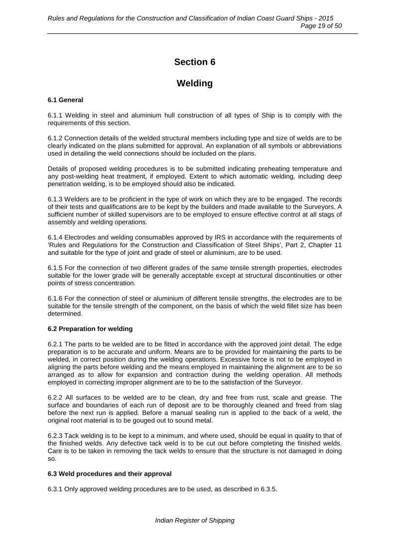
Rules and Regulations for the Construction and Classification of Indian Coast Guard Ships - 2015
Page 19 of 50
Section 6
Welding
6.1 General 6.1.1 Welding in steel and aluminium hull construction of all types of Ship is to comply with the requirements of this section. 6.1.2 Connection details of the welded structural members including type and size of welds are to be clearly indicated on the plans submitted for approval. An explanation of all symbols or abbreviations used in detailing the weld connections should be included on the plans. Details of proposed welding procedures is to be submitted indicating preheating temperature and any post-welding heat treatment, if employed. Extent to which automatic welding, including deep penetration welding, is to be employed should also be indicated. 6.1.3 Welders are to be proficient in the type of work on which they are to be engaged. The records of their tests and qualifications are to be kept by the builders and made available to the Surveyors. A sufficient number of skilled supervisors are to be employed to ensure effective control at all stags of assembly and welding operations. 6.1.4 Electrodes and welding consumables approved by IRS in accordance with the requirements of ‘Rules and Regulations for the Construction and Classification of Steel Ships’, Part 2, Chapter 11 and suitable for the type of joint and grade of steel or aluminium, are to be used. 6.1.5 For the connection of two different grades of the same tensile strength properties, electrodes suitable for the lower grade will be generally acceptable except at structural discontinuities or other points of stress concentration. 6.1.6 For the connection of steel or aluminium of different tensile strengths, the electrodes are to be suitable for the tensile strength of the component, on the basis of which the weld fillet size has been determined. 6.2 Preparation for welding 6.2.1 The parts to be welded are to be fitted in accordance with the approved joint detail. The edge preparation is to be accurate and uniform. Means are to be provided for maintaining the parts to be welded, in correct position during the welding operations. Excessive force is not to be employed in aligning the parts before welding and the means employed in maintaining the alignment are to be so arranged as to allow for expansion and contraction during the welding operation. All methods employed in correcting improper alignment are to be to the satisfaction of the Surveyor. 6.2.2 All surfaces to be welded are to be clean, dry and free from rust, scale and grease. The surface and boundaries of each run of deposit are to be thoroughly cleaned and freed from slag before the next run is applied. Before a manual sealing run is applied to the back of a weld, the original root material is to be gouged out to sound metal. 6.2.3 Tack welding is to be kept to a minimum, and where used, should be equal in quality to that of the finished welds. Any defective tack weld is to be cut out before completing the finished welds. Care is to be taken in removing the tack welds to ensure that the structure is not damaged in doing so. 6.3 Weld procedures and their approval 6.3.1 Only approved welding procedures are to be used, as described in 6.3.5.
Indian Register of Shipping

Chapter 5 : Structures : Steel and Aluminium
Page 20 of 50
6.3.2 Structural arrangements are to be such as to allow adequate access for satisfactory completion of all welding operations. Welded joints are to be so arranged so as to facilitate downhand welding wherever possible. 6.3.3 The sequence of welding is to be so planned that any restraint during welding operations is reduced to a minimum. The ends of the frames and stiffeners should be left unattached to the plating at the subassembly stage until connecting welds are made, in the intersecting systems of plating, framing and stiffeners, at the erection stage. Where a butt meets a seam, the welding of the seam should be interrupted well clear of the junction and not be continued until the butt is completed. Welding of the butt should continue past the open seam and the weld be chipped out for the seam to be welded straight through. 6.3.4 Adequate precautions are to be taken to ensure that the welding site is protected from the deleterious effects of high moisture, severe wind and extreme cold. 6.3.5 Unless previously approved, welding procedures are to be established by the yard and forwarded to IRS for approval. The welding procedure specifications are to include detailed description of the base material, primer, plate thickness range, joint/groove design, welding consumable, welding position, welding techniques, welding parameters, preheating / interpass temperature and post heat treatment if any. The welding for procedure qualification and subsequent testing, are to be witnessed by the IRS Surveyor. 6.4 Inspection of welds 6.4.1 Effective arrangements are to be provided for the inspection of finished welds to ensure that all welding has been satisfactorily completed. 6.4.2 All finished welds are to be visually inspected and are to be sound, uniform and substantially free from slag inclusions, porosity, undercutting or other defects. Welds and adjacent base metal are to be free from injurious arc strikes. 6.4.3 For the examination of important structural welds, visual inspection is to be supplemented by radiography or other acceptable non- destructive crack or flaw detection methods. The extent of such examination is to be to the Surveyors' satisfaction, but particular attention is to be given to the following locations: a) Junction and crossings of seams and butts in strength deck, sheer strake, side and bottom shell
within 0.4L amidships. b) Butts of keel plating and rounded sheerstrake within 0.4L amidships. c) Insert plates in way of hatch openings on the strength deck. d) Butts of longitudinal framing and longitudinal bulkhead stiffeners within 0.4L amidships. 6.4.4 Defective sections of welds as found by visual or non- destructive examination or leakages under hydrostatic tests, are to be gouged out as necessary and carefully rewelded. 6.5 Butt welds 6.5.1 Plates of equal thickness may be manually butt welded as per Fig. 6.5.1. For automatic welding procedures and special welding techniques, the welding procedure will be specially considered.
Indian Register of Shipping

Rules and Regulations for the Construction and Classification of Indian Coast Guard Ships - 2015
Page 21 of 50
6.5.2 For joints of plates with difference in thickness of more than 4 [mm], the thicker plate is to be tapered. The taper is not to exceed 1:3. Edge preparation after the tapering is to be as indicated in 6.5.1 above. 6.5.3 All manual butt welds are normally to be welded from both sides. Where a back ceiling run is not practicable or in certain cases when the stress level in the members is very low, welding on one side may be permitted provided the welding process is found satisfactory. 6.5.4 Where stiffening members, attached by continuous fillet welds, cross the finished butt or seam welds, these welds are to be made flush in way of the faying surface. Similarly for butt welds in webs of stiffening members, the butt weld is to be first completed and made flush with the stiffening member before the stiffener is connected to the plating by fillet weld. The ends of the flush portion are to run out smoothly without notches or any sudden change of section. Where such conditions can not be complied with, a scallop is to be arranged in the web of the stiffening member. Scallops are to be of such size and in such a position, that a satisfactory weld can be made.
Indian Register of Shipping

Chapter 5 : Structures : Steel and Aluminium
Page 22 of 50
Fig.6.5.1 : Typical manually welded butt joints
Square butt
Single bevel butt Double bevel butt
θο = 50o – 70o
α o = 90 o
θ o = 50o
h
6 ≤ h ≤ t/3 mm
R≤3 mm
t >19 mm
R ≤3 mm
R ≤3 mmR≤3 mm
θ o = 30 o - 45 o
θο = 50o – 70o
R≤3 mm
Single vee butt
Single vee butt, one side welding with backing strip(temporary or permanent)
Double vee butt, uniform bevels
t t
t
G = 3 - 9 mm
t
t≤ 5mm
t >5 mm
Double vee butt, non-uniform bevel
G = 1.5 - 3.0 mm
G = 1.5 - 3.0 mm
G = 1.5 - 3.0 mm G = 1.5 - 3.0 mm
G = 1.5 - 3.0 mm G G = 1.5 - 3.0 mm
θο = 50o – 70o θο = 50o – 70o
Indian Register of Shipping

Rules and Regulations for the Construction and Classification of Indian Coast Guard Ships - 2015
Page 23 of 50
Fig.6.6.1 : Intermittent fillet welds
6.6 'T' connections 6.6.1 The throat thickness (See Fig.6.6.1) of the fillet welds is given by: throat thickness = tp . weld factor. d/s where, tp = thickness [mm], of the thinner of the two parts being connected. d = distance [mm], between the successive weld fillets. s = length [mm], of the correctly proportioned weld fillets, clear of end craters s is not to be less than 75 [mm]. The weld factors for various connections are generally to be as given in Table 6.6.1. Where an approved automatic deep penetration procedure is used, the weld factors may be reduced by 15 per cent.
Indian Register of Shipping

Chapter 5 : Structures : Steel and Aluminium
Page 24 of 50
Table 6.6.1 : Weld factors for fillet welds
Structural items Weld factors
Permitted type of weld Remarks Double
Cont. Intermi-ttent
Bottom Structure Center girder To keel plate or bar
keel 0.3 *
Double continuous welding is required in bottom impact area.
See 6.6.5(g)
To face plate 0.15 * To inner bottom 0.25 *
Side girder To bottom shell 0.15 * To face plate 0.13 * To floors 0.20 * To inner bottom 0.15 *
Floors To keel plate 0.15 * To shell plating 0.15 * To centre girder 0.35 * To longitudinal bulkheads
0.35 *
To inner bottom 0.15 * To face plate 0.15 * Stern-tube covering 0.15 *
Bottom and inner bottom longitudinals, frames
To shell plating 0.13 *
Inner bottom To side shell 0.4 * Stiffeners To floors and girders 0.13 * Structure in Machinery Space Floors and girders To shell and inner
bottom 0.3 *
See Note 1
To face plate 0.2 * Transverse and longitudinal frames
To shell plating 0.15 *
Floors To centre girder in way of engine, thrust blocks and boiler seatings
- In single bottom 0.50 * - In double bottom 0.30 *
Main engine foundation
To top plate 0.5 *
Girders To hull structure 0.4 * Floors To engine girder 0.4 * Brackets etc. To engine girders 0.3 * Side Structure Transverse frames To side shell
- In tanks 0.13 * - Elsewhere 0.11 *
Side longitudinals To shell plating 0.13 * Web frames and side stringers
To shell plating - Within 0.2 x
span from ends 0.35 *
- Elsewhere 0.20 * To face plate and tripping bracket
0.15 *
Web frames To side stringers 0.3 *
Indian Register of Shipping

Rules and Regulations for the Construction and Classification of Indian Coast Guard Ships - 2015
Page 25 of 50
Table 6.6.1 : Weld factors for fillet welds (Continued….)
Structural items Weld factors
Permitted type of weld Remarks Double
Cont. Intermi-ttent
Deck Structure Strength deck To shell F.P.
See Note 2 Generally
Other decks To shell and bulkheads
0.3 *
Deck beams To deck plating - In tanks 0.13 * - elsewhere 0.11 *
Deck longitudinals To decks 0.13 * Deck girders To deck plating
- Within 0.2 x span from ends
0.35 *
- Elsewhere 0.20 * - To face plating
and tripping brackets
0.15 *
Cantilever webs To shell, decks, face plates and longitudinal girders at ends
0.35 *
Pillars To deck, inner bottom and pillar brackets
0.40 *
Bulkheads and Partitions Boundaries of Watertight, oiltight
and wash bulkheads and shaft tunnels
0.4 *
Stiffeners On tank and wash bulkheads
0.13 *
On pillar bulkheads 0.13 * On ordinary bulkheads
0.11 *
Vertical and horizontal girders in tanks and wash bulkheads
To bulkhead plating - Within 0.2 x
span from ends 0.40 *
- Elsewhere 0.30 * - To faceplate 0.30 * - To tripping
brackets 0.15 *
Vertical and horizontal girders elsewhere
To bulkhead plating - Within 0.2 x
span from ends 0.35 *
- Elsewhere 0.20 * To faceplate and tripping brackets
0.15 *
Indian Register of Shipping
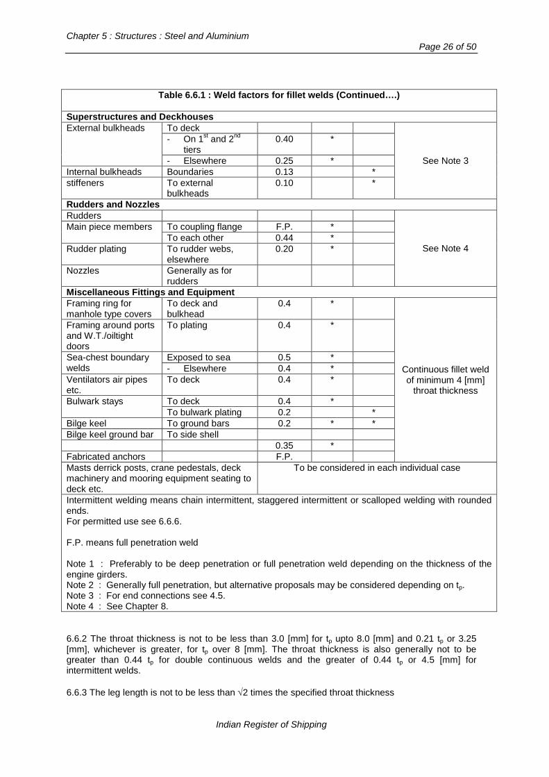
Chapter 5 : Structures : Steel and Aluminium
Page 26 of 50
Table 6.6.1 : Weld factors for fillet welds (Continued….)
Superstructures and Deckhouses External bulkheads To deck
See Note 3
- On 1st and 2nd tiers
0.40 *
- Elsewhere 0.25 * Internal bulkheads Boundaries 0.13 * stiffeners To external
bulkheads 0.10 *
Rudders and Nozzles Rudders
See Note 4
Main piece members To coupling flange F.P. * To each other 0.44 *
Rudder plating To rudder webs, elsewhere
0.20 *
Nozzles Generally as for rudders
Miscellaneous Fittings and Equipment Framing ring for manhole type covers
To deck and bulkhead
0.4 *
Continuous fillet weld of minimum 4 [mm]
throat thickness
Framing around ports and W.T./oiltight doors
To plating 0.4 *
Sea-chest boundary welds
Exposed to sea 0.5 * - Elsewhere 0.4 *
Ventilators air pipes etc.
To deck 0.4 *
Bulwark stays To deck 0.4 * To bulwark plating 0.2 *
Bilge keel To ground bars 0.2 * * Bilge keel ground bar To side shell 0.35 * Fabricated anchors F.P. Masts derrick posts, crane pedestals, deck machinery and mooring equipment seating to deck etc.
To be considered in each individual case
Intermittent welding means chain intermittent, staggered intermittent or scalloped welding with rounded ends. For permitted use see 6.6.6. F.P. means full penetration weld Note 1 : Preferably to be deep penetration or full penetration weld depending on the thickness of the engine girders. Note 2 : Generally full penetration, but alternative proposals may be considered depending on tp. Note 3 : For end connections see 4.5. Note 4 : See Chapter 8. 6.6.2 The throat thickness is not to be less than 3.0 [mm] for tp upto 8.0 [mm] and 0.21 tp or 3.25 [mm], whichever is greater, for tp over 8 [mm]. The throat thickness is also generally not to be greater than 0.44 tp for double continuous welds and the greater of 0.44 tp or 4.5 [mm] for intermittent welds. 6.6.3 The leg length is not to be less than √2 times the specified throat thickness
Indian Register of Shipping

Rules and Regulations for the Construction and Classification of Indian Coast Guard Ships - 2015
Page 27 of 50
6.6.4 Where the connection is highly stressed, deep penetration or full penetration welding may be required. Where full penetration welding is required, the abutting plate may require to be beveled. (See Fig. 6.6.4).
G ≤2
αο = 50o – 70o βο = 70o – 90o
Small angle fillet
θο = 30ο − 45ο
Single bevel tee with permanent backing
Single bevel tee
θο = 50o R ≤ 3 mm R = 3 mm
G = 2.5 - 4 mm
θο≥ 35o
r
r = 12 - 15 mm
Single 'J' tee
θ = 50
R≤3 mm
G ≤3 mm
Double bevel tee symmetrical
t >19 mm
R≤3 mm
G≤3 mm
Double bevel tee assymetrical
G = 2.5 - 4 mm
θ ≥35o
r
r = 12 - 15 mm
(Not normally for strength members)
t
t
G ≤ 3 mm
t
50o
G ≤ 6 mm
t>19 mm
Double J bevel symmetrical
R ≤3 mm
50o
Fig. 6.6.4 : Typical edge preparations for manually welded ‘T’ or cross joints
Indian Register of Shipping
Chapter 5 : Structures : Steel and Aluminium
Page 28 of 50
6.6.5 Continuous welding is to be adopted in the following locations and may be used elsewhere if desired. a) Boundaries of weathertight decks and erections, including hatch coamings, companionways and
other openings. b) Boundaries of tanks and watertight compartments. c) All structures in the afterpeak and the afterpeak bulkhead stiffeners. d) All welding inside tanks intended for chemicals or edible liquids if any. e) All lap welds in tanks. f) Bottom framing structure in machinery spaces. g) Where loading is mainly of dynamic nature e.g. bottom plating subjected to slamming and
forebody side or bow impact area. h) Under side of cross deck structure in case of multi-hull Ship. i) Primary and secondary members to plating in way of end connection and end brackets to
plating in the case of lap connection. j) Where the thickness of the abutting member (i.e. stiffener web) is greater than 15 [mm] and also
exceeds the thickness of the table member (e.g. plating). k) Other connections as given in Table 6.6.1. 6.6.6 Where intermittent welding is used, the welding is to be made continuous around the ends of brackets, lugs, scallops and at other orthogonal connections with other members. Where intermittent welding is permitted as per Table 6.6.1, only scalloped welding is to be used in tanks for water ballast, cargo oil or freshwater. Chain or staggered intermittent welding may be used in dry spaces or tanks arranged for fuel oil only. 6.6.7 Where structural members pass through the boundary of a tank, and leakage into the adjacent space could be hazardous or undesirable, full penetration welding is to be adopted for the members for at least 150 [mm] on each side of the boundary. Alternatively, a small scallop of suitable shape may be cut in the member close to the boundary outside the compartment, and carefully welded all round. 6.7 Lap connections 6.7.1 Overlaps are not to be used to connect plates which may be subjected to high tensile or compressive loading. However, where they are adopted, the width of overlap is to be adequate to ensure a good weld, the surfaces are to be in close contact and the joints should be closed all round by continuous fillet weld. 6.8 Slot weld 6.8.1 For the connection of plating to internal webs, where access for welding is not practicable, the closing plating is to be attached by continuous full penetration or slot welds to flat bars fitted to the webs. Slots are to be well rounded at ends, to have a minimum length of 75 [mm] and in general, a minimum width of twice the plating thickness. The distance between the slots is not to exceed 150 [mm]. Complete filling of the slots is normally not permitted.
Indian Register of Shipping

Rules and Regulations for the Construction and Classification of Indian Coast Guard Ships - 2015
Page 29 of 50
6.9 End connection 6.9.1 In way of the end connections of girders double continuous welding is to be used all around. The weld area is not to be less than the cross-sectional area of the member, and the throat thickness not less than that given by Table 6.6.1 for girder ends. 6.9.2 Where stiffeners have bracketed end connections, bracket arms are to be welded all around and the throat thickness is not to be less than 0.35 times the thickness of bracket. 6.9.3 Where stiffeners are continuous at girder, they are to be connected to the webs, either directly and/or by means of lugs. The weld area is to be such that the shear stress does not exceed 80/k [N/mm2]. Where the shear forces are high, a double sided connection to the web and/or a web stiffener welded on top of the continuous stiffener may be required. 6.10 Butt straps for aluminium alloy 6.10.1 In general the scantlings of welded structures are to be determined using the mechanical properties of aluminium alloy in the welded condition. However, where stiffeners are butt welded, consideration would be given to the use of suitable butt straps on the flanges which sufficiently reinforce the area of the weld to allow the scantlings to be determined using unwelded mechanical properties. The butt weld is to be completed and made flush with the flange of the stiffening member before the butt strap is fitted and the butt strap weld is to be continuous. The scantlings, arrangements and locations of all joints and butt straps are to be submitted for approval in such cases. Mechanical tests may also be required to be carried out to demonstrate the effectiveness of such arrangements.
Section 7
Direct Strength Analysis
7.1 General 7.1.1 Application 7.1.1.1 Previous sections gives prescriptive requirements to determine the scantlings of the hull
girder as a whole and individual strength members consisting of platings, secondary stiffeners, primary girders and other supporting structures such as pillars etc. When the scantlings as determined by the prescriptive requirements are to be additionally verified by direct strength assessment, the requirements of this Chapter are to be applied. In such cases class notation “DSA (Seastate, Speed)” will be assigned as per 7.1.1.3.
7.1.1.2 Direct Strength Assessment consists of: - Creation of 3D FE model as specified in Section 7.2 - Computation of Load sets as specified in Section 7.3 - Structural analyses for each load set as specified in Section 7.4 - Strength check against specified criteria as specified in Section 7.5 - Adjustment of scantlings and re-analyses, if necessary
A flowchart of the finite element analysis procedure for the direct strength assessment is shown in Fig 7.1.1.2.
Indian Register of Shipping

Chapter 5 : Structures : Steel and Aluminium
Page 30 of 50
7.1.1.3 For class notation ”DSA (Seastate, Speed)” The hull girder and local loads for this additional assessment are to be determined by direct hydrodynamic calculation method specified in Sec. 3.1 and 3.3, considering the stated operating environment of sea state & ship speed combination.
7.1.2 Computer programs 7.1.2.1 Computer programs for FE analysis and where applicable, for Hydrodynamic analyses, are
to be suitable for the intended analyses and also providing reliable results to the satisfaction of IRS.
7.1.2.2 The computer program used for structural analyses is to take into account the combined
effects of bending, shear, axial and torsional moments or forces. 7.1.2.3 The computer program used for hydrodynamic analysis is to be based on established 2D/3D
methods capable of determining ship motions, accelerations, global hull girder moments and forces and local dynamic pressures.
Demand
Loading Conditions & Load Cases
Light Weight Still water loads
Wave Loads
Capability of the hull structure
3 D Model
Boundary Conditions
Calculation - Deformation - Stress
Strength Criteria - Yielding - Buckling
Adjustment of Scantlings
END of Analysis
YES
Indian Register of Shipping

Rules and Regulations for the Construction and Classification of Indian Coast Guard Ships - 2015
Page 31 of 50
7.1.2.4 Considering the types of load components and the structural responses which are of primary interest, the computer program used for structural analysis based on formulations derived from linear idealizations are sufficient. The adequacy of the selected software is to be demonstrated satisfactorily.
7.1.3 Submission of analysis report A detailed report of direct strength FE analyses is to be submitted for information. The report is to include the following items as a minimum: a) List of drawings/plans used in the analysis, including their versions and dates b) Detailed description of structural modeling principles and any deviations/assumptions in the
model from the actual structures c) Documentation in respect of the computer program used for transfer of the hydrodynamic loads
to the 3D FE structural model is to be submitted. d) Plots of structural model e) Material properties, plate thickness and beam properties used in the model f) Details of boundary conditions g) All loading conditions analyzed h) Data for loads application i) Summaries and plots of calculated deflections j) Summaries and plots of calculated stresses k) Details of buckling strength assessment l) Tabulated results showing compliance with the design criteria m) Reference of the finite element computer program, including its version and date. 7.2 Structural Analyses – Modeling & Procedure 7.2.1 Purpose 3D FE structural analyses as specified in this section are to be carried out to verify that the following are within the acceptance criteria when subjected to the specified static and dynamic loads:
a) Stress level in the longitudinal hull girder members, primary supporting members and the transverse bulkheads. b) Buckling capability of plates and stiffened panels and other primary supporting members subjected to compressive stresses. c) Deflection of primary supporting members.
7.2.2 Extent of model 7.2.2.1 The minimum extent of the hull structure model is to be such as to cover all compartments that lie within the region of 0.6L amidships. Where, there is a significant change in the structural arrangement or special features, the extent may have to be suitably increased. The overall analyses may comprise of structural analyses carried out in parts. The extent of the structure included in each “part model ” is to cover at least three compartments. The transverse
Indian Register of Shipping

Chapter 5 : Structures : Steel and Aluminium
Page 32 of 50
bulkheads at the ends are to be included, together with their associated structures. Both ends of the model are to form vertical planes. The FE model is to include both sides of ship structures allowing application of the unsymmetrical loads. 7.2.2.2 Where the global/part model analysis reveals local areas of high stress or stress concentration, a further investigation using local fine mesh model would be required. Appropriate boundary conditions determined from the larger scale model are to be imposed in the local models to ensure structural continuity and load transfer between the two levels of models. 7.2.3 Finite element modeling 7.2.3.1 All main structural members (plates, stiffeners, girders and pillars) detailed are to be represented in FE model, e.g.: − inner and outer shell, − inner bottom and decks − transverse and longitudinal bulkheads − floors / girders systems / pillars and secondary stiffeners associated with the above mentioned
plating 7.2.3.2 Mesh boundaries of finite elements are to simulate the stiffening systems on the actual structures as far as practical and are to represent the correct geometry of the panels between stiffeners. Similarly, sufficient compatibility between the hydrodynamic and structural models is to be ensured so that the application of fluid pressures onto the finite element mesh of the structural model can be done appropriately. 7.2.3.3 Stiffness of each structural member is to be represented by using element type appropriately as given below :
(1) Stiffeners are to be modeled by beam elements having axial, torsional, bi-directional shear and bending stiffness. However, stiffeners on girder webs and face plates of primary supporting members may be modeled by bar elements having only axial stiffness and a constant cross-sectional area along its length.
(2) Plates are to be modeled by shell element having out-of-plane bending stiffness in addition
to bi-axial and in-plane stiffness. However, membrane element having only bi-axial and in-plane stiffness can be used for plates that are not subject to lateral pressures. For membrane and shell elements, only linear quad or triangle elements, as shown in Fig 7.2.3.3, are to be adopted. Triangle elements are to be avoided as far as possible, especially in highly stressed areas and in areas around openings and at bracket connections where significant stress gradient should be predicted.
Indian Register of Shipping

Rules and Regulations for the Construction and Classification of Indian Coast Guard Ships - 2015
Page 33 of 50
Fig. 7.2.3.3 : Linear Membrane and Shell Quad & Triangle Elements 7.2.3.4 When orthotropic elements are not used in FE model:
− mesh size is to be equal to or less than the representative spacing of secondary stiffeners on the relevant load bearing plating e.g. deck, shell, bulkhead plating
− stiffeners are to be modeled by using beam or bar elements, as per 7.2.3.3 (1) above − In spaces such as a double bottom, webs of primary supporting members e.g. double
bottom girders and plate floors, are to be divided in at least four rows of elements, height-wise
− In general, girders and transverses and deep stiffeners, large end brackets etc. are to be modeled by using shell elements for web and shell or beam or bar elements for face plate.
− aspect ratio of all shell elements is not to exceed 1:4. 7.2.4 Boundary conditions 7.2.4.1 General requirements The model of the hull girder structure should be close to equilibrium state when all the loads (static and dynamic) are applied. Any unbalanced forces in the model’s global axis system for each load case need to be determined and resolved appropriately. The magnitude of the unbalanced forces, and the procedure used to balance the structural model in equilibrium is to be fully documented. The boundary conditions applied to the model are to be such as to closely represent the physical structural behaviour, a standard method for this purpose is given in 7.2.4.2. 7.2.4.2 Standard method At both end sections of a part model, the point of intersection of neutral axis with the ships’ centerline, located within the transverse bulkhead, is to be considered as a “Master Node”. These “Master Nodes” are to have support conditions as given in Table 7.2.4.1. Other nodes on the longitudinal members at each end section are to be linked to the respective “Master Node” as shown in Table 7.2.4.2, so that the transverse sections remain plane after bending.
Indian Register of Shipping

Chapter 5 : Structures : Steel and Aluminium
Page 34 of 50
Table 7.2.4.1: Support condition of Master Node
Location Translational Rotational
Dx Dy Dz Rx Ry Rz
Master Node on aft end of the model - Fixed Fixed - - -
Master Node on fore end of the model Fixed Fixed Fixed Fixed - -
Dx, Dy and Dz mean restrains on displacements along X, Y and Z axis, respectively. Rx, Ry and Rz mean restrains on rotations about X, Y and Z axis, respectively. X, Y and Z axes are in the longitudinal, transverse and vertical directions respectively.
Table 7.2.4.2: Rigid Plane links at both end sections
Nodes on longitudinal members at both ends of the model
Translational Rotational
Dx Dy Dz Rx Ry Rz
RL RL RL - - -
RL means linked to the applicable “Master Node” to allow the necessary degrees of freedom (displacements) in relation to the “Master Node”, so that the transverse sections at ends remain plane after bending.
7.2.5 Loading conditions 3D FE analyses are to be carried out considering the ship loading conditions and load cases specified in Section 7.3. 7.2.6 Consideration of hull girder loads 7.2.6.1 The hull girder loads to be considered for each loading condition are to consist of the still water loads and appropriate values of wave-induced loads based on the Load Combination Factors (LCFs) given in Section 7.3. These are to be applied at the Master Nodes at the end sections of the part model. Thus, the vertical bending moment, M V and the horizontal bending moment, M H to be applied at each master node are given by : M V = MSW + LCF. MWV M H = LCF. MWH Where, MSW: Design vertical Still water bending moment, See Chapter 3 MWV: Vertical wave bending moment, in hogging or sagging condition, See Chapter 3 MWH: Horizontal wave bending moment, See Chapter 3 LCF: The Load Combination Factor applicable for the load component corresponding to the load case being considered. LCF is to be determined by hydrodynamic analysis using the Equivalent Design Wave method given in 7.3.
Indian Register of Shipping

Rules and Regulations for the Construction and Classification of Indian Coast Guard Ships - 2015
Page 35 of 50
In addition to the above, incremental corrections M V_T _INCR and M H_T_INCR to the vertical bending moment and the horizontal bending moment to account for the moments caused by the application of local loads within the FE model, are to be applied at each web frame between the aft and forward end sections. See 7.2.6.3. These correction moments may be equally distributed on the nodes on longitudinal members at that section. M V_T _INCR = M V_T (at the web frame under consideration) – M V_T (at the web frame immediately aft of that under consideration) M H_T_INCR = M H_T (at the web frame under consideration) – M H_T (at the web frame immediately aft of that under consideration)
M V_T and M H_T at any web frame between the aft and forward end sections are to be obtained as per 7.2.6.2. 7.2.6.2 Alternatively, the superimposition method can be used to consider the effect of hull girder loads in the overall strength assessment. In this method, instead of applying the hull girder vertical and horizontal bending moments on the model, the resulting stresses are superimposed on to the stresses obtained from the structural analysis based on the local lateral loads. The hull girder stress,
SIMσ , in each element participating in the longitudinal strength is given by :
( )_ _
N/ z /V T H T
SIMY Z
M MI z I y
σ = −−
Where,
YI : Vertical inertia of the section under consideration about the horizontal neutral axis
ZI : Horizontal inertia of the section under consideration about the vertical neutral axis ( Z axis ) zN : Distance of the horizontal neutral axis above base line y: Y co-ordinate of the element z: Z co-ordinate of the element MV_T, MH_T: Target (equivalent) vertical and horizontal bending moments at the section under consideration, respectively, after taking into account the required corrections due to local loads, M V_T = MV – M V_FEM M H_T = MH – M H_FEM M V_FEM: Local vertical bending moment correction due to local loads as per 7.2.6.3 M H_FEM: Local horizontal bending moment correction due to local loads as per 7.2.6.3 7.2.6.3 The vertical and horizontal bending moment corrections M V_FEM and M H_FEM respectively, are the moments caused by the application of local loads within the FE model, which at each web frame between the aft and forward end sections, may be obtained from a 2D beam model, simply supported at the forward & aft end and subjected to summation of all loads in Z and Y directions, respectively. The vertical and horizontal bending moments, M V_FEM and M H_FEM respectively, are the required corrections to account for the moments caused by the application of local loads within the FE model.
Indian Register of Shipping

Chapter 5 : Structures : Steel and Aluminium
Page 36 of 50
The values of moment corrections M V_FEM and M H_FEM at each web frame between the aft and forward end sections, may be obtained from an independent 2D beam model simply supported at the forward & aft ends and subjected to summation of all loads in Z and Y directions, respectively. 7.3 Design Loads for Direct Strength Assessment 7.3.1 General 7.3.1.1 Direct Strength Assessment is to performed for the following two ship loading conditions: a) Deep Condition b) Light Seagoing condition - as defined in Part 3, Chapter 6.
7.3.1.2 For each loading conditions, three load cases for the wave-induced loads are to be considered for the structural analysis. The three load cases are: (i) Load Case 1 - Wave Bending Moment Dominant (Hogging) – Head Sea (ii) Load Case 2 - Wave Bending Moment Dominant (Sagging) – Head Sea (iii) Load Case 3 - Pressure at Waterline Dominant - Beam Sea
The hull girder and local loads to be considered for each load case are to consist of the static (still water) loads and appropriate values of the dynamic (wave-induced) loads considering the wave heading and the phase difference between the load component under consideration and the dominant load. 7.3.1.3 Where the Class notation “DSA (Seastate, Speed)” is to be assigned, the design values for various local and global load components (for the additional load cases specified in 7.3.2 ) are to be obtained by direct hydrodynamic calculations as per the requirements given in section 7.3.2. 7.3.2 Design loads for Class Notation “DSA( Seastate, Speed )” 7.3.2.1 The direct hydrodynamic analyses are to be performed for the combination of sea state and speed as stated in the desired class notation. The values of significant wave heights to be used in the analyses are to be taken as per Table 7.3.2.1 below, depending on the specified sea state.
Table 7.3.2.1 Significant Wave heights for the Sea states
Sea State Significant Wave Height (m.)
0-1 0.10 2 0.50 3 1.25 4 2.50 5 4.00 6 6.00 7 9.00 8 14.00 9 > 14
Indian Register of Shipping

Rules and Regulations for the Construction and Classification of Indian Coast Guard Ships - 2015
Page 37 of 50
Unless accurate information on the range of peak period, Tp, [sec] is supplied by the designer, the following range is to be considered for determining the peak period to be used in the calculations for hydrodynamic loads. The chosen peak period is to match that at which the relevant RAO is the maximum.
13 30S P SH T H< <
where,
SH is the significant wave height [m].
7.3.2.2 A flowchart of the hydrodynamic analysis procedure for determination of the loads for the required additional strength assessment is shown in Fig 7.3.2.2 below :
Indian Register of Shipping
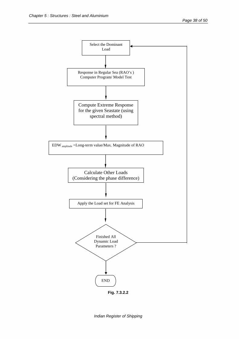
Chapter 5 : Structures : Steel and Aluminium
Page 38 of 50
Fig. 7.3.2.2
Select the Dominant Load
Response in Regular Sea (RAO’s ) Computer Program/ Model Test
Compute Extreme Response for the given Seastate (using
spectral method)
EDW amplitude =Long-term value/Max. Magnitude of RAO
Calculate Other Loads (Considering the phase difference)
Finished All Dynamic Load Parameters ?
END
Apply the Load set for FE Analysis
Indian Register of Shipping

Rules and Regulations for the Construction and Classification of Indian Coast Guard Ships - 2015
Page 39 of 50
7.3.2.3 Three load cases each corresponding to a dominant load parameter are to be considered for the strength assessment. The dominant load parameters are given below:
i. Wave Bending Moment (Hogging) – Head Sea ii. Wave Bending Moment (Sagging) – Head Sea iii. Pressure at Waterline – Beam Sea
For each load case the most probable extreme value of the dominant load component should be calculated considering the 3 hours exposure. The other load components are to be calculated using equivalent design wave concept given in section 7.3.2.5. 7.3.2.4 The extreme values for each dominant load parameter is evaluated using the spectral analysis based approach. In this approach the response amplitude operators (RAO’s) should be calculated for the range of frequencies corresponding to a wavelength of LR/5 to 5LR, where LR is the rule length. Care should be taken to include the possible peak in the RAO. 7.3.2.5 Equivalent Design Wave (EDW) for each load case is the sinusoidal wave of such amplitude and frequency that produces the most probable extreme value of the dominant load component corresponding to the load case (see 7.3.2.3). The amplitude, Wζ , of the each EDW is given by:
Most Probable Extreme ValueMaximum magnitude of RAOWζ =
The frequency of the each EDW is the frequency at which the peak of the corresponding dominant load component RAO occurs. 7.3.2.6 Values of other load components, i.e. other than the dominant load component, are to be obtained by a hydrodynamic analysis carried out using a sinosidal wave of the amplitude and frequency of the equivalent design wave determined as per 7.3.2.5. The snapshot values that occur at the wave position when the dominant load reaches its peak value are to be used to define the load set for each load case. 7.3.3 Structural weight 7.3.3.1 Effect of the hull structure weight due to gravity is to be included. The dynamic load components due to various acceleration from self-weight are to be ignored. Standard density of steel will be taken as 7.85 t/m3. 7.4 Analysis Criteria 7.4.1 Validity of results for strength assessment Generally, the results obtained for mid region of the structural model are considered valid for assessment against the specified criterion, results in areas close to where the boundary conditions have been applied are to be ignored.
Indian Register of Shipping

Chapter 5 : Structures : Steel and Aluminium
Page 40 of 50
The results of the structural analysis are to satisfy the criterion for yielding strength, buckling strength and deflection, as given in 7.4.2 to 7.4.4 below. 7.4.2 Yielding strength assessment 7.4.2.1 Reference stresses Based on the results of the FE analyses, the Reference stress for various structural elements is to be taken as :
− Von Mises equivalent stress at centre of a plane element in case of shell or membrane elements
− Combined axial + bending stress in case of a beam element, and − Axial stress in case of a bar element
Where, Von Mises equivalent stress, eqσ , is given by :
222 3 xyyyxxeq τσσσσσ ++−=
σx, σy: Element normal stresses, τxy: Element shear stress 7.4.2.2 Allowable stress The Reference stresses for steel structures are not to exceed 235/k N/mm2, where k is the material factor as per Chapter 2, Cl. 2.2. For aluminum structures, the Reference stresses are not to exceed 200/ka N/mm2, where ka is the material factor as per Chapter 2, Cl. 3.2. 7.4.3 Local buckling strength assessment 7.4.3.1 The requirements in respect of buckling strength assessment described in this Section are independent of that given in 1.1.3, which relate to determination of the scantlings as per prescriptive Rules. Buckling strength assessment is to be carried out for the plating and stiffened panels in areas where high compressive stresses are developed. The assessment is to be carried out for such panels in longitudinal hull girder structural members, primary supporting structural members and transverse bulkheads – i.e. deck, bottom & side shell, double bottom, double side, transverse and longitudinal bulkhead structures and transverse and vertical web frames, floors, girders, stringers, etc. The buckling assessment is to be based on the net thickness obtained by deducting the full corrosion addition thickness from the gross scantlings provided. The method used for buckling analysis is to be based on non-linear analysis techniques, or equivalent, which predict the complex behaviour of stiffened and un-stiffened panels subjected to simultaneous application of bi-axial compression/tension, shear and lateral pressure. The method is also to be capable of taking into account the following to satisfaction of IRS :
Indian Register of Shipping

Rules and Regulations for the Construction and Classification of Indian Coast Guard Ships - 2015
Page 41 of 50
(a) non- linear geometrical behaviour (b) inelastic material behaviour (c) initial deflections - geometrical imperfections/out-of flatness (d) welding residual stresses (e) interactions between buckling modes and structural elements; plates, stiffeners, girders etc. (f) boundary conditions as per section 7.4.3.3 The utilisation factor, η , is used as a measure of safety margin available against buckling failure.
For combined loads, the utilisation factor, η , is defined as the ratio between the applied equivalent
load and the equivalent membrane loads which would result in reaching the maximum buckling capacity of the panel. A structure is considered to have an acceptable buckling strength when 1.0η ≤ .
7.4.3.2 Panel stresses to be considered The buckling assessment is to be based on membrane stress evaluated at the centroid of the plate elements. Where shell elements are used, stresses at the mid plane of the element are to be used for the buckling assessment. For the purpose of buckling analyses, the relevant stress components in each panel are to be obtained according to the following procedure :
1) When the mesh model differs from the elementary plate panel geometry, the stresses σx , σy and τ acting on an elementary plate panel are to be evaluated by extrapolation and/or interpolation using the element stresses in the surrounding meshes.
2) Where the membrane the stresses σx* and σy
* are both compressive stresses, they may be reduced for the purpose of buckling assessment to take account of the Poisson effect, the reduced stresses xσ and yσ , are given by :
( )* * 2. / (1 )x x yσ σ µ σ µ= − −
( )* * 2. / (1 )y y xσ σ µ σ µ= − − Where, µ is the P ois on’s ratio for the
material 3) determine stress distributions along edges of the considered buckling panel by
introducing proper linear approximation as shown in Fig 7.4.3.1 4) calculate edge factor Ψ
Indian Register of Shipping

Chapter 5 : Structures : Steel and Aluminium
Page 42 of 50
Figure 7.4.3.1 : Stresses of Panel for buckling assessment
7.4.3.3 Boundary conditions Buckling load cases are to be applied suitably to the buckling panel under evaluation, depending on the stress distribution and geometry. In general simply supported boundary conditions of all edges will be applied. 7.4.4 Deflection of primary girders The maximum relative deflection of primary girders is not to exceed the following criteria:
max 325ilδ =
where: δmax: Maximum relative deflection [mm] li : Span of primary girder [mm]
Section 8
Helicopter Decks
8.1 General 8.1.1 Application 8.1.1.1 The requirements of this section apply to vessels provided with helicopter landing area located on an appropriate location on the weather deck or on a platform specifically erected for this purpose. The section also provides the requirements in respect of helicopter manoeuvring and stowage on decks. Ships complying with the requirements of this section will be eligible to be assigned the class notation “HELIDK”. 8.1.1.2 The scantlings of all structures in way of the helicopter landing and operations area are also to comply with the requirements for exposed decks in the same position and the requirements for structures subjected to wheeled loads as given in Section 9. 8.1.1.3 Attention is drawn to the requirements of Indian Coast Guard and other Statutory Authorities concerning the construction of helicopter landing platforms and the operation of helicopters, which
Indian Register of Shipping
Rules and Regulations for the Construction and Classification of Indian Coast Guard Ships - 2015
Page 43 of 50
are to be complied with. Consideration is to be given to airflow over the landing area & surrounding structures. 8.1.1.4 These rules assume that the helicopters are fitted with oil/gas dampers and pneumatic type under carriages, arrangements other than these, will be specially considered. 8.1.2 Definitions 8.1.2.1 OLEO load is defined as the load, which will cause the damper and tyre combination to reach the end of their travel. 8.1.2.2 The All-Up-Weight (AUW) is the maximum weight that will be encountered for the specific application under consideration. It includes the maximum total weight of helicopter, personnel, fuel and payload. 8.1.3 Documentation 8.1.3.1 Plans showing the proposed scantlings and arrangements of the structure are to be submitted for approval. The type, size, the OLEO load and AUW weight of each of the helicopters to be used are also to be indicated. 8.1.3.2 Details of arrangements for securing the helicopter to the deck are to be submitted for approval. 8.1.3.3 A landing guide should be provided as part of the ships’ documentation. This is to contain all the relevant information of the helicopters on which the helicopter deck design has been based, identification of landing, parking and maneuvering areas, tie down arrangements, weights and a summary of the design calculations. 8.1.4 Flight deck arrangements 8.1.4.1 The landing area is to be sufficiently large to allow for the landing and maneuvering of the helicopter, and is to be approached by a clear landing and take-off sector complying with the applicable regulations. 8.1.4.2 Normally, for maximum flexibility in helicopter operations, the landing area is to be taken as a square, with each side not less than 1.25 times the rotor diameter. Where the operation of helicopters is restricted to known helicopter types, the areas of deck structure to be assessed for the landing condition are to be taken as squares, with each side not less than two times the maximum wheel strut spacing. The squares are to be centered on all the normal landing points, at all specified landing orientations, for all helicopters. 8.1.4.3 The takeoff and landing area are generally to be free of projections above the level of the deck. Projections above 25 mm may only be permitted where allowed by the helicopter undercarriage design standard. Projections outside the landing and takeoff areas are to be kept to a minimum such that they do not hinder helicopter maneuvering operations.
Indian Register of Shipping

Chapter 5 : Structures : Steel and Aluminium
Page 44 of 50
8.1.4.4 The structure is to be designed to accommodate the largest helicopter type which it is intended to use. It is advised that an allowance be made for future growth of the helicopter weight such that future operations are not restricted to lower sea states. 8.1.4.5 Suitable arrangements are to be made to minimize the risk of personnel or machinery sliding off the landing area. A non-slip surface and anchoring devices, and in the case of independent platforms, safety nets, are to be provided. 8.1.4.6 The following lighting arrangements are to be provided for the helicopter landing area as per the requirements of the Indian Coast Guard Authority.
a) Safe landing area perimeter indicting lights; b) Flood lights / LED arrays for illumination of landing area; c) Obstacle marking lights.
8.1.5 Fire safety 8.1.5.1 The requirements in respect of fire protection of helicopter landing, maneuvering and parking areas and in way of the helicopter facilities, are to comply with the requirements given in Chapter 9 Section 7. 8.2 Design Loads 8.2.1 Helicopter deck loading 8.2.1.1 The load cases to be applied to all parts of the structure are defined in Table 8.2.1.1.
Table 8.2.1.1: Tyre Force Loading
Tyre Force to be considered
Structural element >> For Plating For Stiffening
Load Case Fpl kN
Fstiffr kN
Helicopter Landing Cases
Crash Landing 1.2 * f1 * Woleo 1.6 * f1 * Woleo
Normal Landing 0.6 *1.2 * f1 *Woleo 0.6 * 1.6 * f1 * Woleo
Operation on decks
Manoeuvring 1.6 * f2 * Wty 1.6 Wty
Parking ( stowed condition ) (1 + 0.6 av/g) * f2 * Wty (1 + 0.6 av/g) * f2 * Wty
Indian Register of Shipping

Rules and Regulations for the Construction and Classification of Indian Coast Guard Ships - 2015
Page 45 of 50
Table 8.2.1.1 (Contd.) Where, f1 = 1.15 for landing decks over magazines, manned spaces, e.g. deckhouses, bridges, control rooms, etc. = 1.0 elsewhere f2 = 1.10 for exposed decks = 1.0 for internal decks not directly exposed to weather Wty = static load, on the tyre print, in kN; with the centre of gravity in a position that causes the highest load. In the absence of specific helicopter manufacturers’ information on the static distribution of load, Wty may be taken as Wauw divided equally between the two main undercarriages ignoring the nose or tail wheel. For helicopters with twin main rotors Wty is to be taken as Wauw distributed between all main undercarriages in accordance with the static load distribution. Woleo = Oleo Ultimate Load, kN (and not collapse load, which refers to complete failure) of undercarriage Wauw = the maximum all up weight of the helicopter, in kN, as defined in 8.1.2.2 av = vertical acceleration [m/s2], See Chapter 3, Cl 2.1.3
8.3 Scantlings
8.3.1 Helicopter deck scantling 8.3.1.1 The scantlings of helicopter deck structures are to meet the requirements given in Section 3.2 below for helicopter landing cases and those given in Section 8.3.3 below for cases related to helicopter operation on decks using respective loads as given in Table 8.2.1.1. 8.3.2 Scantlings for helicopter landing loads
8.3.2.1 Deck Plating The net thickness ’ nett ’ of deck plating subjected to landing loads as defined in Sec 8.2, is not to be
less than :
2 pl_landingnet 1 a
c b s pt f [mm]
m. Y
Cσ
=
where, The deck panel dimensions a,b,s,l [mm], fa , C2 and m are as given for plating in, Section 9.3.1 and
pl_landingp = Fpl_landing 103 / ( a.b ) [N/mm2] Fpl_landing = Tyre force for plating & the landing case under consideration, as per Table 8.2.1.1 [kN]
Indian Register of Shipping

Chapter 5 : Structures : Steel and Aluminium
Page 46 of 50
C1 = 1.8 for crash landing case, and = 2.1 for normal landing case
8.3.2.2 Deck Stiffeners
The scantlings of stiffeners subjected to Crash/Normal Landing are also to meet the following requirements: - The net section modulus is not to be less than:
3 stiffr_landing
a
c ab p Z
m σl
= [cm3]
Where,
stiffr_landingp = Fstiffr_landing 103 / ( a.b ) [N/mm2] Fstiffr_landing = Tyre force for stiffener & the landing case under consideration, as per Table 8.2.1.1 [kN] C3 and m are as given for stiffeners in Section 9.3.2
aσ = Yσ for for crash landing case, and
= as given in Table 9.3.2.1 for normal landing case Suitable lugs are to be fitted in way of crossing of deck stiffeners and the primary girders to provide weld connection on either side of the stiffener . The total area of the weld connection as well as the area of the stiffener web, each is not to be less than:
3 22
w5R(m 2m 2)A [ ]cm
τ− +
= ,
where,
2[N/mm ]3Yστ =
R = Fstiffr_landing for the crash landing case m = a/ l 8.3.2.3 Deck primary girders The scantlings of girders will be specially considered based on the most severe location of the tyre print. The resulting stresses, based on net scantlings, are not to exceed allowable stress, aσ , is not
to exceed 0.9 Yσ for crash landing case, and aσ as given in Table 9.3.3.1 for normal landing case.
The deflection of the girder due to landing loads is not to be greater than (1/325)th of the span of the girder.
Indian Register of Shipping

Rules and Regulations for the Construction and Classification of Indian Coast Guard Ships - 2015
Page 47 of 50
8.3.3 Scantlings for loads related to helicopter manoeuvring and stowage on decks 8.3.3.1 The scantlings of deck plating, stiffeners and primary girders in respect of loads related to helicopter operations on decks are to be determined in accordance with Sec 9- Vehicle Decks. However, the tyre print pressure as per Sec 9 is to obtained by using the Fplating in lieu of “W”. Where, Fplating = Tyre Force as per Table 8.2.1.1 in Manoeuvring or Stowed condition whichever is greater :
Section 9
Vehicle Decks
9.1 General
9.1.1 Application, definitions, documentation 9.1.1.1 This Section provides the requirements in respect of decks subjected to loads from wheeled vehicles, which are to be complied with in addition to the general requirements in this chapter. These requirements can also be applied to or inner bottoms or platforms or ramps subjected to loads from wheeled vehicles. Ships complying with these requirements would be eligible to be assigned the class notation “Vehicle Deck “. 9.1.1.2 The requirements given below are based on the assumption that each structural element i.e. deck plating panel and/or stiffener under consideration is subjected to one load area only (see Fig.9.2.1.1) at a given instant and that the element is continuous over several evenly spaced supports. The requirements for other loads and/or boundary conditions will be specially considered. 9.1.1.3 A "load area" is the tyre print area of individual wheels, for closely spaced wheels it may be taken as the enveloped area of the wheel group. See Fig. 9.2.1.1 9.1.1.4 The details of wheel loadings are to be forwarded for information and they are to include the proposed arrangement and dimensions of tyre prints, axle and wheel spacing, maximum axle load and tyre pressure, for each one of the vehicles envisaged. 9.2 Design Loads 9.2.1 Wheel loads 9.2.1.1 The pressure 'p' from the wheels on deck is to be taken as:
]N/mm[10.)a5.081.9(.n.a.bWp 23
v+=
where, W = maximum axle load, [t]. For forklift trucks, the total weight is to be taken as the axle load. n = number of "load areas" per axle a = extent [mm], of the load area parallel to the stiffener (see Fig.9.2.1.1) b = extent [mm], of the load area perpendicular to the stiffener (see Fig.9.2.1.1) av = vertical acceleration [m/s2],See Chapter 3, Cl 2.1.3
Indian Register of Shipping

Chapter 5 : Structures : Steel and Aluminium
Page 48 of 50
Figure 9.2.1.1 Plate panel and load area
9.3 Scantlings
9.3.1 Deck plating 9.3.1.1 The net thickness 't' of deck plating subjected to wheel loadings is not to be less than;
2a
c bs pt 2.1 f [mm]m. aσ
=
where, fa = (1.1 - 0.25 s/l) for s ≤ l, however need not be taken as greater than 1.0 a,b,s,l = deck panel dimensions [mm] (see Fig.9.2.1.1), however for the purpose of these calculations ‘b’ is not to be taken as greater than ‘s’. p = wheel pressure as per 9.2.1.1
,)8.1a/s(
2.43.1c 22 +−= However, need not be taken as greater than 1.0
s.bfor5.6)b/s(7.4b/s)(
38m 2 ≤+−
=
aσ = allowable as per Table 9.3.1.1 below
Table 9.3.1.1 : Allowable stress σa , for plating [N/mm2]
Plating ( σa )
Contributing to the hull girder longitudinal strength
Longitudinally framed plating 0.95 σY - 0.45 | σL |, not to be taken greater than 0.9σY
Transversely framed plating 0.95 σY - 0.9 | σL |, not to be taken greater than 0.9σY
Not contributing to the hull girder longitudinal strength 0.9σY
b
a
l
s
Indian Register of Shipping
Rules and Regulations for the Construction and Classification of Indian Coast Guard Ships - 2015
Page 49 of 50
σL_ = the hull girder bending stress at the load point under consideration, calculated based on the global loads in Chapter 3, Cl 4.1 9.3.2 Deck stiffeners 9.3.2.1 The net section modulus 'Z' of deck beams and longitudinals subjected to wheel loadings is not to be less than:
3 33c .a.b. .pZ 10 [cm ]m a
lσ
−=
where, c3 = (1.15 -0.25 b/s) for b ≤ s, however need not be taken as greater than 1.0
5.6/7.4)/(rm 2 +−
=lala
r = 29 for continuous stiffeners supported at girders = 38 when the continuous stiffeners can be considered as rigidly supported at girders against rotation.
aσ = allowable as per Table 9.3.2.1 below:
Table 9.3.2.1 : Allowable stress values σa, for stiffeners
Ordinary stiffener Allowable stress value, σas
Longitudinal stiffeners contributing to the hull girder longitudinal strength
σY - |σL|, not to be taken greater than 0.83σY
Longitudinal stiffeners in long deck houses
To be specially considered based on their effectiveness in respect of longitudinal strength
Other stiffeners 0.83σY σL_ = the hull girder bending stress at the load point under consideration based on the global loads in 4.1 of Chapter 3. 9.3.2.2 Suitable lugs are to be fitted in way of crossing of deck stiffeners and the primary girders to provide weld connection on either side of the stiffener. The total area of the weld connection as well as the area of the stiffener web, each is not to be less than:
3 22
w5R(m 2m 2)A [ ]cm
τ− +
= ,
where,
2[N/mm ]3aστ =
R = p a b. 10-3 [kN] m = a/ l
Indian Register of Shipping

Chapter 5 : Structures : Steel and Aluminium
Page 50 of 50
9.3.3 Deck girders 9.3.3.1 The scantlings of girders will be specially considered based on the most severe condition of moving or stowed vehicles (also see 9.1.1.3.). The resulting stresses, based on net scantlings, are not to exceed allowable stress, aσ , as per Table 9.3.3.1 below.
Table 9.3.3.1 : Allowable stress values σa, for primary girders Girder Allowable stress value, σa
Longitudinal girder contributing to the hull girder longitudinal strength
σY -|σL|, without being taken greater than 0.8σY
Other girders 0.8σY σL = the hull girder bending stress at the load point under consideration based on the global loads in 4.1 of Chapter 3. The deflection of the girder is not to be greater than (1/325)th of the span of the girder.
End Of Chapter
Indian Register of Shipping
Rules and Regulations for the Construction and Classification of Indian Coast Guard Ships - 2015
Page 1 of 27
Chapter 6
General Hull Requirements for Fibre Composite and Sandwich Constructions
Contents
Section
1 Principles of Scantlings and Structural Details 2 Requirements for Manufacturing Facilities 3 Production Procedures, Workmanship and Manufacturing Control 4 Details and Fastenings 5 Material Properties and Testing 6 Hull Girder Strength 7 Sandwich Plate Panels 8 Single Skin Plate Panels 9 Stiffeners, Primary Girders and Pillars
Section 1
Principles of Scantlings and Structural Details 1.1 Application 1.1.1 The Rules in this chapter apply to glass reinforced unsaturated polyester (GRP) structures of single skin construction and sandwich construction. Structures using fibre-reinforced plastics other than GRP may be accepted upon special consideration. 1.12 Scantlings of various laminates, stiffeners and girders satisfying the local strength requirements are to be determined in accordance with the general principles given in this chapter. Scantlings of hull members contributing to the longitudinal strength are also to comply with the requirements of Section 6. 1.1.3 The design values of loads to be considered are given in Chapter 3. 1.1.4 In certain cases additional check to investigate the buckling strength of hull members subjected to compressive stresses may be required. 1.2 Symbols s = spacing of stiffener [mm] b = unsupported panel breadth [mm], See Fig. 7.3.2. l = span of stiffener or girder [m]
Indian Register of Shipping
Chapter 6 : General Hull Requirements for Fibre Composite and Sandwich Constructions
Page 2 of 27
p = design pressure [kN/m2] as per 1.1.3 Gc = the glass content by weight of the reinforcement within the laminate G = shear modulus of sandwich core material [N/mm2] σu = ultimate tensile or compressive stress, as applicable, for the laminate under consideration [N/mm2] Ei = tensile modulus of individual laminate, [N/mm2] tc = core thickness [mm] τu = ultimate shear stress of the laminate under consideration [N/mm2]. 1.3 Frame spacing 1.3.1 The normal frame spacing ‘sr’ may be taken as 350 + 5L [mm]. 1.3.2 Where the actual spacing of stiffeners differs from the normal frame spacing sr, the minimum thickness requirements specified in this Chapter for various structural members is to be corrected in direct proportion to the frame spacing, however, any reduction in thickness is not to be more than 30%. 1.4 Stiffeners and girders 1.4.1 For girders and stiffeners, the span ‘l’ [m] is to be taken as the length of the girder or stiffener between the two supporting members less the depth of girder or stiffener on crossing panel if any, with correction for end brackets as shown in Fig. 1.4.1(a) and 1.4.1(b). For curved or knuckled stiffeners, ‘l’ may be based on the chord length. 1.4.2 The area of the attached plating to be used in the calculation of sectional properties of the stiffeners and girders, is to be taken as the cross sectional area within the effective width of the attached plating as given in 1.4.3 1.4.3 In case of single-skin laminates, the effective width ‘w’ of plating attached to a stiffener or girder is to be taken as the mean stiffener or girder spacing in [mm] or ( 18 t + bw) [mm ], whichever is less where, t = thickness of plating [mm] and bw = net width of stiffener [mm]. See Fig. 1.4.3. Where FRP sandwich laminate plating with an effective (balsa or marine plywood or plastic) core is used, “t” in the above equation is to be taken as the thickness of a single-skin laminate having the same moment of inertia per unit width as the two skins of the sandwich. For a stiffener along an opening, the effective plating width is to be taken as either half the stiffener spacing in [mm] or ( 9t + b ) [mm], whichever is less. 1.4.4 The effective cross sectional area of the attached plating is not to be less than that of the faceplate. 1.4.5 The effective cross sectional area of the girder web Aw is to be taken as per Chapter 5, Section 1.4.8.
Indian Register of Shipping

Rules and Regulations for the Construction and Classification of Indian Coast Guard Ships - 2015
Page 3 of 27
1.5dw
dw
l
le
le
le/2
θ >150o
Fig. 1.4.1 (a) and (b)
9t 9t
t
bw
w=18t+bw
Fig. 1.4.3 1.4.6 The proportions of stiffeners and girders with hollow form or nonstructural cores or forms, including ineffective wood cores (softwoods used below the waterline are considered to be ineffective), are to conform with Fig.1.4.6. The widths and heights of the stiffeners are to be not greater than:
Indian Register of Shipping

Chapter 6 : General Hull Requirements for Fibre Composite and Sandwich Constructions
Page 4 of 27
w = 20 t1 [mm] h = 30 tw [mm] Where, w = width of stiffener face [mm] h = height of stiffener webs [mm] t1 = thickness of stiffeners face [mm] tw = thickness of stiffener webs and flanges [mm]. The thickness of the web of an inverted angle or T bar stiffener or girder is not to be less than twice the web thickness specified for hollow forms. For encapsulated effective wood or plywood core, webs and faces are not subjected to the above mentioned thickness limitations, however, minimum thickness of the web and face is to be 3 [mm].
h
ω t1 Hat
section
t
≅3t t
Minimum lap greater of 0.2h or 50 [mm]; may not be greater than 6t
Fig. 1.4.6 : Proportions and connections of stiffeners
1.4.7 Shear ties (stiffeners) Where the total web depth to thickness ratio requirement in 1.4.6 for buckling of stiffener webs is not complied with, cross linking of the stiffener webs at the Rule depth to thickness ratio is to be provided by the use of shear ties, as indicated in Fig.1.4.7. Alternative arrangements will be subject to individual consideration in conjunction with submitted direct calculations.
Web depth Unsupported
2nd tie
1st tie
Fig. 1.4.7 : Arrangement of shear ties (stiffeners)
Indian Register of Shipping

Rules and Regulations for the Construction and Classification of Indian Coast Guard Ships - 2015
Page 5 of 27
1.4.8 Where openings are cut in the girder web, they are to be away from the girder ends and scallops for stiffeners, with their centre location as near to the neutral axis of the girder as practicable. Openings of depth exceeding 25% of the girder depth or 300 [mm] and of length exceeding the depth of the girder or 60% of the secondary stiffener spacing, are to be suitably reinforced all around at the edge 1.4.9 Girders are to be provided with adequate lateral stability by tripping brackets fitted generally at every alternate stiffener in case of asymmetrical section or at every fourth stiffener in case of symmetrical section. Tripping brackets are also to be fitted at the toes of end brackets and in way of concentrated loads such as heels of pillars or cross ties. 1.5 End attachments 1.5.1 The end attachment of stiffeners and girders are to ensure good structural continuity. As far as practicable the stiffeners and girders are to be continuous through and adequately supported at the supporting members. In case of connections side frame to deck beams or where it is not feasible to provide the continuity, the stiffeners and girders may be abutted provided brackets as required by 1.5.2 are fitted. Typical acceptable arrangements are shown in Fig.1.5.1.
Continuous face
reinforcement
Beam knee
Deck beam
Side frame
Bracket Longit- udinal Girder
Continu-ous face reinforc-ement
Transverse frame
Supporting BHD
Taper 1:4 min.
Girder
Fig. 1.5.1 : End attachments 1.5.2 In general, the thickness of webs and flanges of the stiffeners or girders is to be continued over the bracket region. The bracket arm length (including the depth of the stiffener or girder) is not to be less than 1.5 times the depth of the stiffener or girder. 1.6 Bottom structures 1.6.1 In Ships of single skin construction, the bottom structures are normally to be longitudinally stiffened. In Ships with sandwich construction, adequate longitudinals or longitudinal girders are to be provided in way of shear ties see 7.2.3 and may also be provided to support the bottom panels.
Indian Register of Shipping

Chapter 6 : General Hull Requirements for Fibre Composite and Sandwich Constructions
Page 6 of 27
The bottom longitudinals are to be supported by bottom transverses or bulkheads spaced not more than 2 metres apart. 1.6.2 Web frame rings continuous around the transverse cross section of the Ship are to be arranged in line with the bottom transverses. Where intermediate floors are fitted for additional bottom support, their ends are to be well tapered or connected to local panel stiffening. 1.6.3 In the engine room, floors are generally to be fitted at every frame. The floors are preferably to be carried continuously through the engine girders. In way of thrust bearings additional strengthening is to be provided. 1.6.4 Bottom longitudinal girders in general, are to spaced 2.5 m and are to be carried continuously through bulkheads. A centre girder is to be fitted for docking purposes if the external keel or bottom shape does not give sufficient strength and stiffness. 1.6.5 Main engines are to be supported by longitudinal girders with suitable local reinforcement to take the engine and gear mounting bolts. Rigid core materials are to be applied in all through bolt connections. Also see 4.7 for inserts. 1.6.6 Adequate number of manholes are to be provided for easy access to all parts of the double bottom. Exposed edges of openings in sandwich constructions are to be sealed with resin impregnated mat see 4.8 for details. All openings are to have well-rounded corners. 1.7 Side structures 1.7.1 The Ship sides may be longitudinally or vertically stiffened. 1.7.2 In open deck Ships, the top ends of the stiffeners are to be efficiently connected to fore and aft gunwale at deck line. 1.8 Deck structure 1.8.1 Decks of single skin construction are normally to be longitudinally stiffened. 1.8.2 In areas subjected to high compressive stresses additional transverse intermediate stiffeners may have to be fitted to ensure adequate buckling strength. 1.8.3 Hull to deck connections details are to be as per 4.10. 1.9 Bulkhead structures 1.9.1 Number and location of transverse watertight bulkheads are to be in accordance with the requirements given in Chapter 4, Section 4. 1.9.2 Bulkheads are to be suitably strengthened at the ends of deck girders and where subjected to concentrated loads. 1.10 Bow protection 1.10.1 For Ship of composite sandwich construction the fore foot region upto atleast one frame spacing abaft of the stem, is to be so designed that in the event of local impact the effect of damage will be limited. This may be achieved by providing an additional sacrificial nose or sheathing or by arranging the individual plies of the laminate such that any delamination due to the impact will be directed to the outer surface of the laminate.
Indian Register of Shipping
Rules and Regulations for the Construction and Classification of Indian Coast Guard Ships - 2015
Page 7 of 27
1.11 Superstructures and deckhouses 1.11.1 In superstructures and deckhouses, the front bulkhead is to be in line with a transverse bulkhead in the hull below or be supported by a combination of girders and pillars. The after end bulkhead is also to be effectively supported. As far as practicable, exposed sides and internal longitudinal and transverse bulkheads are to be located above girders and frames in the hull structure and are to be in line in the various tiers of accommodation. Where such structural arrangement in line is not possible other effective supports are to be arranged. 1.11.2 Sufficient transverse strength is to be provided by means of transverse bulkheads or girders supported by web frames. 1.11.3 At the break of superstructures, which have not set-in from the ship’s side, the side plating is to extend beyond the ends of the superstructure and is to be gradually reduced in height down to the deck or bulwark. The transition is to be smooth and without local discontinuities. 1.11.4 Openings in the sides of deckhouses are to have well-rounded corners. Large openings in sides of deckhouses are to be substantially stiffened along the edges. 1.11.5 Machinery casings supporting one or more decks above are to be adequately strengthened. 1.12 Bulwarks 1.12.1 Bulwark sides shall have the same scantlings as required for a superstructure in the same position. 1.12.2 A strong flange is to be made along the upper edge of the bulwark. Bulwark stays are to be arranged in line with transverse beams or local stiffening. The stays are to have sufficient width at deck level. If the deck is of sandwich construction solid core inserts are to be fitted at the foot of the bulwark stays. Stays of increased strength are to be fitted at ends of bulwark openings. Openings in bulwarks are not to be situated near the ends of superstructures. 1.12.3 Where bulwarks on exposed decks form wells, ample provision is to be made to facilitate freeing the decks of water.
Section 2
Requirements for Manufacturing Facilities
2.1 Storage of raw materials 2.1.1 Storage premises are to be so equipped and arranged that the respective material supplier’s recommendations for correct storage and handling of the raw materials are complied with. 2.1.2 Storage premises for glassfibre are to be kept clean and as free from dust as possible, so that the raw material is not contaminated. Glassfibre parcels are also to be protected against rain and moisture. 2.1.3 The glass fibre materials are to be stored for at least two days in storage premises where the relative humidity of air is not higher and the air temperature is not lower than that in the moulding shop. 2.1.4 The resins are to be stored under dry, well-ventilated conditions, in accordance with the material supplier’s recommendations. Resins which are stored at temperatures lower than + 18oC are to be pre-conditioned to the moulding shop temperature prior to use. 2.1.5 Core materials are to be stored dry and protected against mechanical damage.
Indian Register of Shipping

Chapter 6 : General Hull Requirements for Fibre Composite and Sandwich Constructions
Page 8 of 27
2.2 Manufacturing conditions 2.2.1 Manufacturing premises are to be so equipped and arranged that the material supplier's directions for handling the materials, the laminating process and curing conditions can be followed. 2.2.2 The air temperature in the moulding shops is not to be less than + 18oC and in general, not more than 30oC. The air temperature is to be attained at least 24 hours before commencement of lamination and is to be maintained within ±3oC throughout the moulding area during the lay-up and curing period. 2.2.3 The relative humidity of the air is to be kept below the dew point to avoid condensation and is in any case not to exceed 75%. In areas where spray moulding is taking place, the relative humidity is not to be less than 40%. 2.2.4 Air temperature and relative humidity are to be recorded at all necessary locations regularly. 2.2.5 Arrangements are to be made to prevent draught and direct sunlight in places where lamination and curing are in progress. 2.2.6 Sufficient scaffoldings are to be arranged so that all lamination work can be carried out without operators standing on the core or on surfaces on which lamination work is taking place. 2.2.7 Fabrication of flat panels is to be carried out on a support lifted from the workshop floor level.
Section 3
Production Procedures, Workmanship and Manufacturing Control
3.1 General 3.1.1 Fabrication of all major structural parts is to be carried out in accordance with the approved production plan and by skilled operators. Any deviations from this plan are required to be approved by the surveyor prior to commencement of the work. 3.1.2 Raw materials for all structural members covered by the Rules are to be of approved type in accordance with Chapter 2. The supplier’s directions for application of the materials are to be followed. 3.2 Manual lamination 3.2.1 The reinforcement material is to be applied in the approved sequence. 3.2.2 Changes in laminate thickness are to be made using a gradual taper. The length of such taper is, in general, not to be less than 20 times the difference in thickness. Where the construction changes from sandwich laminate to a solid laminate, the thickness of the core material is, in general, to be reduced by a gradual taper of not less than 2:1. Also see Fig.7.1.3. 3.2.3 When the laminate is applied in a mould a chopped strand mat of max. 450 g/m2 is to be applied next to the gelcoat. 3.2.4 Polyester resin is to be applied on each layer of reinforcement. Gas and air pockets are to be worked out of the laminate by regular rolling, generally before the next layer is applied. Rolling of the layers are to be made carefully, paying special attention to sharp corners and transitions.
Indian Register of Shipping
Rules and Regulations for the Construction and Classification of Indian Coast Guard Ships - 2015
Page 9 of 27
3.2.5 The time interval between applications of each layer of reinforcement is to be within the limits specified by the material supplier. For thicker laminates care is to be taken to ensure a time interval sufficiently large to avoid excessive heat generation. 3.2.6 Curing systems are to be selected with due regard to the reactivity of the polyester and in accordance with the supplier’s directions. Heat development during curing is to be kept at a safe level. The quantity of curing agents is to be kept within the limits specified by the supplier. 3.2.7 After completion of lamination the laminates are to cure for at least 48 hours at an air temperature of not less than 18oC. Curing at a higher temperature and a shorter curing time may be accepted on the basis of control of the curing rate. 3.3 Spray moulding 3.3.1 The term spray moulding is understood to mean the simultaneous deposit of polyester resin and fibreglass reinforcement. Manufacturers using this method are subject to special approval. 3.3.2 When approval of the spray moulding process is considered, special attention will be paid to production arrangement, ventilation equipment, the manufacturer's own quality control systems and other factors of significance to the quality of the finished product. 3.3.3 Spray moulding of structural members is to be carried out only by specially approved operators. 3.3.4 The equipment used for spray moulding is to give an even and homogenous build-up of the laminate. Any dosage devices are to ensure an even application of additives to the polyester resin. No fibres are to be shorter than 20 mm in length. 3.3.5 In addition to ensuring an even application during the spray moulding over the entire surface, regular rolling out of the sprayed-on layers is to be carried out. Immediately next to the gelcoat, the rolling out is to be done before the thickness of finished laminate reaches 1.5 mm and thereafter for every 2.5 mm of thickness of subsequent layers. The rolling out is to be done thoroughly to ensure adequate compression and removal of gas and air pockets. Special care is to be taken at sharp transitions and corners. 3.4 Sandwich lay-up 3.4.1Sandwich constructions can be fabricated either by lamination on the core (e.g. plug moulding), application of the core against a wet laminate or by gluing the core against a cured skin laminate. 3.4.2 Efficient bond is to be obtained between the skin laminates and the core and between the individual core elements. Approved tools for cutting, grinding etc. of various types of core material are to be specified in the production procedure. The bond is to be verified by shear or tensile testing. 3.4.3 All joints between skin laminates and core and between the individual core elements are to be completely filled with resin, glue or filler material. 3.4.4 Core materials with open cells in the surface are normally to be impregnated with resin before it is applied to a wet laminate or before lamination on the core is commenced. 3.4.5 When the core is applied manually to a wet laminate the surface is to be reinforced with a chopped strand mat of 450 g/m2 on plane surface and 600 g/m2 on curved surfaces. The core material is to be laid onto the pre-moulded skin as soon as possible after the laminate cure has passed the exothermic stage. 3.4.6 Frameworks for core build up are to give the core sufficient support to ensure stable geometrical shape of the construction and a rigid basis for the lamination work.
Indian Register of Shipping

Chapter 6 : General Hull Requirements for Fibre Composite and Sandwich Constructions
Page 10 of 27
3.4.7 When a prefabricated skin laminate is glued to a sandwich core, measures are to be taken to evacuate air from the surface between skin and core. 3.4.8 The core material is to be free from dust and other contamination before the skin laminates are applied or core elements are glued together. 3.4.9 Where a core is to be applied to an uneven surface, the Surveyor may request additional building up of the surface or contouring of the core to suit. 3.4.10 In general laminates are to be staggered by 50 mm per layer of reinforcement. Where very thin sandwich skins are adopted the rate of laminate stagger will be individually considered. The plans are to clearly show the staggering of successive plies in both the transverse and longitudinal directions. 3.4.11 Thermoforming of core materials is to be carried out in accordance with the manufacturer’s recommendations. Maximum temperature limits are to be strictly observed. 3.5 Secondary bonding 3.5.1 A secondary bonding is any bond between two GRP structures which is made after one or both of the individual structures has effectively cured. Normally, the laminating is to proceed as a continuous process, as far as practicable, with the minimum of delay between successive plies. Where a secondary bond is required to be made, it is to be carried out in accordance with the resin manufacturer’s recommendation, details of which are to be incorporated in the builder’s quality control documentation. This will, in general, take the form of the area being lightly abraded and wiped with a suitable solvent, which is to be allowed to dry prior to laminating. 3.5.2 The surface ply of a laminate subject to secondary bonding and the first ply of the bonding laminate is normally to be of chopped strand mat to enhance the interlaminar strength of the laminate. 3.5.3 Surfaces in way of secondary bonding are to be clean and free from dust. 3.5.4 If a laminate subject to secondary bonding has cured for more than 5 days the surface is to be ground. If resin containing wax is used, grinding is required if the curing time exceeds 24 hours. 3.5.5 Consideration is to be given, especially in highly stressed areas, to the application of peel ply materials to obviate contamination of the exposed surface, and thereby reducing the abrading required to obtain a good secondary bond. If “peel strips” are used in the bonding surface the required surface treatment may be dispensed with. 3.6 Faults 3.6.1 All faults are to be classified according to their severity and recorded, together with the remedial action taken, under the requirements of the quality control systems. The documentation is to be made available during surveys and for works approval. 3.6.2 Production faults are to be brought to the attention of the attending Surveyor and a rectification scheme agreed upon. 3.7 Repair 3.7.1 Minor repairs are to be agreed with the attending Surveyor prior to being carried out. The builder is to incorporate details of the agreed repair procedures in the quality control system for the Ship.
Indian Register of Shipping

Rules and Regulations for the Construction and Classification of Indian Coast Guard Ships - 2015
Page 11 of 27
3.7.2 Where required, plans giving details of the proposed structural modifications or repairs are to be submitted for approval, prior to execution. 3.8 Inspection 3.8.1 It is the builder’s responsibility to carry out the inspections required in accordance with the accepted quality control system. 3.8.2 The Surveyors will monitor the builder’s quality control records and carry out inspections of work in progress during their periodical visits. 3.8.3 During inspections, all deviations are to be dealt with under the builder’s agreed quality procedures. 3.9 Acceptance criteria 3.9.1 Classification is dependent upon the work being carried out in accordance with the approved plans and the requirements of an accepted quality system. 3.9.2 The workmanship is to be to the satisfaction of the attending Surveyor. This will include the verification of the quality control documentation and the remedial action associated with all defects and deficiencies recorded. 3.9.3 Proposed deviations from the approved plans are subject to IRS approval. An amended plan is to be submitted for approval prior to any such changes being introduced.
Section 4
Details and Fastenings
4.1 General 4.1.1 The general requirements in respect of details and fastenings given in this section are in addition to the accepted good building practices. Alternative details may be accepted against evidence of satisfactory service experience or test data. 4.2 Alignment 4.2.1 Details of alignment and building tolerances are to be laid down in the builder's production plan. 4.2.2 Where details of alignment and building tolerances are not included on the construction plans, or submitted separately for consideration with the plan submission, they may, subject to individual consideration, be agreed locally with the attending Surveyor. 4.2.3 Particular attention is to be given to the accurate alignment of the following: a) girder abutting single skin bulkhead, b) girder webs with tank sides, c) frames with beams, d) deck and bottom girders with bulkhead or transom stiffeners, e) tank baffles with floors, f) longitudinals where broken at tank ends, and 4.2.4 For larger Ships, the hull breakage sight line is to be progressively monitored during the construction of the Ship and is to form part of the quality control documentation. The production plan is to identify maximum breakage limits dependent upon the size of the Ship.
Indian Register of Shipping

Chapter 6 : General Hull Requirements for Fibre Composite and Sandwich Constructions
Page 12 of 27
4.2.5 The production plan is to identify allowable tolerances for the alignment of the primary structural components. 4.2.6 To ensure efficient load transmission, intercostals, single skin bulkheads are to be aligned to within half the thickness of the thinner bulkhead. In the case of sandwich construction the tolerance requirements will be individually considered dependent upon the sandwich panel dimensions and the construction of the continuous member. In general, the webs of the intercoastal sandwich panel member are to be aligned within 5 mm. Where poor alignment has been identified, additional boundary bonding reinforcements are to be applied as agreed with the attending Surveyor. Any deviations and details of the remedial action taken are to be recorded in the builder's quality control documentation. 4.2.7 To ensure efficient transmission of shear loads, the alignment tolerance of intercoastal ‘top hat’ stiffener webs is, in general, to be within half of the web thickness. Where poor alignment is identified, additional reinforcements are, in general, to be incorporated into the stiffener webs as agreed with the attending Surveyor. Such deviations and details of the remedial action taken are to be recorded in the builder's quality control documentation. 4.3 Continuity 4.3.1 Continuity of all primary structural members is to be maintained and abrupt changes of section are to be avoided. All longitudinal girders and stiffeners are to be continuous through their supporting members. Brackets ending at unsupported sandwich panels are to be tapered smoothly to zero and the panels skin laminate to be locally reinforced at the end of the bracket. Girders are to be fitted with bracket or tapered gradually at ends. See Fig. 1.5.1 4.3.2 Special consideration is to be given to the inter-section of longitudinal and transverse members. In general the ratio between the depths of the intersecting members is to be 2:1. The shallower member is to be continuous under the supporting members. 4.3.3 Alternative proposals to the requirements given in 4.3.2 will be subject to special consideration alongwith details for maintaining the continuity of reinforcements at intersections in both directions which are to be submitted. Where stiffeners are of similar dimensions the primary member is to be continuous. In general, the section modulus of the continuous material is to be maintained. 4.4 Openings 4.4.1 All openings are to have well rounded corners and are to be supported on all sides. Cut edges of openings are to be sealed to prevent the ingress of moisture. 4.4.2 All hatch openings are to be supported by a system of transverse and longitudinal stiffeners, the details of which are to be submitted for approval. 4.4.3 The requirements for closing arrangements and outfit are given in Chapter 4, Section 3. 4.4.4 All deck openings are to have corner radii as specified in Section 6.4.3. 4.4.5 For details of sealing the edges of openings and sandwich panels, see 4.9. 4.5 Through bolting and bolted connections 4.5.1 Bolting arrangements are, in general, to be in accordance with 4.5 to 4.7. The details of all through bolted structural connections including bolt material, proposed number and spacing are to be indicated on the relevant construction plans submitted for approval. The design of the joint is to be suitable for its intended purpose with a sufficient number of bolts to satisfactorily close the joint.
Indian Register of Shipping

Rules and Regulations for the Construction and Classification of Indian Coast Guard Ships - 2015
Page 13 of 27
4.5.2 All fastenings are to be of a suitable marine grade and are to be of a non-corrosive material or protected against corrosion. 4.5.3 In general, large headed bolts or large diameter thick washers are to be used to prevent localised crushing damage during tightening. 4.5.4 Where mechanical fastenings are used, the torque is to be indicated on the plans submitted for approval. 4.5.5 In sandwich constructions, inserts of a material capable of resisting crushing are to be fitted in accordance with 4.7. 4.5.6 The diameter of a fastening is not to be less than the thickness of the thinner component being fastened, with a minimum of 6 mm. 4.5.7 Bolted connections are, in general, to be bonded along all mating surfaces using an accepted structural adhesive, applied in accordance with the manufacturer’s requirements. Where connections rely solely on the shear resistance of the connecting bolts the spacing is not to exceed 3 x the bolt diameter. In areas where subsequent access will either be limited or not possible, self-locking nuts are to be provided. 4.5.8 In general, all structural, bolted connections are to use reeled lines of bolts in accordance with the requirements given in Table 4.5.8.
Table 4.5.8 : Minimum bolt pitch requirements in bonded and bolted connections Location Pitch
Watertight connections - below static load waterline
10 db
Connections in hull above static load waterline to deck 15 db Hull to deck connections - bonded with structural adhesive - bolted with mastic sealant (see note 2)
15 db 8 db
Connections in deckhouses 20 db Deckhouse to deck connections - bonded with structural adhesive - bolted with mastic sealant (see note 2)
15 db 8 db
Minimum distance between reeled lines of bolts 3 db Minimum distance from centreline of line of bolts to free edge 2 db Notes: 1. db is the diameter of the bolt 2. Internal boundary sealing angle to be provided.
4.5.9 All structural, single line, bolted connections without adhesive bonding are to be in accordance with the requirements given in Table 4.5.9.
Table 4.5.9 : Minimum bolt pitch requirements in bolted structural connections
Location Pitch Manhole covers to fuel tanks 6 db Manhole covers to water tanks 8 db Covers over void tanks/cofferdams 10 db Bolted access hatches in decks 10 db Bolted watertight door frames 8 db Window frames 8 db Notes: 1. db is the diameter of the bolt. 2. Internal boundary sealing angle to be provided.
Indian Register of Shipping

Chapter 6 : General Hull Requirements for Fibre Composite and Sandwich Constructions
Page 14 of 27
4.5.10 Care is to be taken to avoid distortion of the frame when window frames are bolted into the structure of the Ship. Where necessary, uneven surfaces are to be locally built upto the satisfaction of the attending Surveyor. 4.5.11 Bolt holes are to be drilled, without undue pressure at break through, having a diametric tolerance of two percent of the bolt diameter. Where bolted connections are to be made watertight the hole is to be sealed with resin and allowed to cure before the bolt is inserted. 4.5.12 In areas of high stress or where unusual bolting configurations are proposed, testing on the basis of equivalence with the above Rules, may be required. 4.6 Through hull fittings 4.6.1 Where fittings penetrate the hull envelope, care is to be taken to seal the hull laminate with resin or other suitable compound. See 4.9. 4.6.2 The areas in way of penetrations for fittings in sandwich construction are, in general, to comply with the requirements of 4.7. Where the requirements cannot be complied with, the core is to be replaced locally with a solid core or very high density foam core with compressive properties commensurate with the loads imposed by the securing arrangements. In areas where localised crushing of a sandwich core is likely to occur, large diameter washers, compression tubes or inserts or a combination of these may to be provided. 4.6.3 All bolted fittings are to be bedded down using a suitable mastic, details of which are to be indicated on the plans for approval. 4.7 Backing bars (inserts) and tapping plates 4.7.1 The requirements for backing plates and bars will be individually considered, on the basis of the loading imposed, details of which are to be indicated on the submitted plans. 4.7.2 Metallic plates and bars are to be suitably protected against corrosion. 4.7.3 Tapping plates may be encapsulated within the laminate, laminated to or bolted to the structure. Where tapping plate edges or corners are likely to give rise to hard spots or stress concentrations the edges are to be suitably rounded. 4.7.4 Where tapping plates are placed on foam cores the plate is to be mounted on a suitable foundation to prevent the movement of the tapping plate during drilling operations. 4.7.5 Direct calculations regarding the scantlings of tapping plates are to be provided at the plan appraisal stage. 4.8 Exposed edges 4.8.1 The exposed edges of all openings cut in single skin laminate panels are to be suitably sealed. Where such edges are in wet spaces or under water the edges of such openings are to have rounded edges and are to be sealed by two plies of 450 g/m2 chopped strand mat (or equivalent) reinforcements. 4.8.2 Exposed edges of openings cut in sandwich panels are to be suitably sealed. The cut edges are, in general, to be sealed with a weight of reinforcement not less than that required for the outer skin of the sandwich. Where other than an epoxy resin system is used the first layer of such reinforcement is to be chopped strand mat with a weight not exceeding 450 g/m2. 4.9 Local reinforcement 4.9.1 Areas subject to local loads or increased stress are to be suitably reinforced, details of which are to be indicated on the submitted plans.
Indian Register of Shipping

Rules and Regulations for the Construction and Classification of Indian Coast Guard Ships - 2015
Page 15 of 27
4.9.2 The hull is to be locally increased by minimum 50% in thickness in way of rudder tubes, propeller brackets, etc. Details of such reinforcements are to be submitted. Local reinforcement is in general to extend under the adjacent supporting structure and then tapered gradually to the base laminate thickness over a distance of minimum 20 times the difference in thickness. 4.10 Hull to deck connections 4.10.1 Details of the hull to deck connection, the method of bonding and the tolerances are to be indicated on the submitted plans. 4.10.2 Hull to deck connections are to be, in general, bolted and over-bonded. A suitable mastic or sealing compound is to be incorporated within the joint. 4.10.3 The bolting details are to be reeled lines of bolts pitched as specified in Tables 4.5.8 and 4.5.9, as applicable. Suitable large diameter thick washers are to be used under both the head and the nut. 4.10.4 Where a mastic is not used, sealing plies are to be applied on the inside of the hull. 4.10.5 The weight of the over-bonding reinforcement is, in general, not to be taken as less than equivalent to the lighter of the component members being connected, and in no case less than equivalent to three plies of 600 g/m2 chopped strand mat. 4.10.6 Substantial beam knees are to be provided to maintain structural continuity between the transverse deck and hull stiffening. 4.10.7 The watertight integrity, continuity and strength of the connection is not to be impaired by the attachment of the hull fender. 4.11 Exhaust systems 4.11.1 Exhaust systems, manufactured from FRP, are to be of the water injected type with a normal operating temperature of 60o to 70oC. 4.11.2 Exhaust pipes, silencers and water separators are to be of a type approved design, installed strictly in accordance with the manufacturer’s requirements. 4.11.3 Where a type approved system is not used, the arrangement will be considered on an individual basis. Resins used in the manufacture of exhaust systems are to be of a type approved by IRS and are to have good heat and chemical resistance properties with a high deflection temperature under load. A vinylester resin is to be used, but a fire retardant polyester resin, having a high heat distortion temperature, will be considered. Test samples may be required dependent upon the proposed arrangement, temperatures and materials. 4.11.4 It is recommended that pigments and additives are not used unless it can be demonstrated that the mechanical properties of the resin system remain unaffected. Resins used are not to show any embrittlement with age. 4.11.5 Special consideration is to be given to post curing of such systems to obtain optimal characteristics. 4.11.6 Due to the weight of water contained within the system, exhaust pipes and fittings are to be efficiently supported. 4.11.7 Exhaust boxes are to be lined with a minimum of two plies of 600 g/m2 chopped strand mat (or equivalent) using a suitable fire retardant/high temperature resin.
Indian Register of Shipping

Chapter 6 : General Hull Requirements for Fibre Composite and Sandwich Constructions
Page 16 of 27
4.11.8 For engineering aspects of exhaust systems reference is to be made to Chapter 12, Section 3.1.4. 4.12 Ballast 4.12.1 The provision of permanent ballast is not to adversely affect the surrounding structure. 4.12.2 Where a resin compound is to be poured into a void space, care is to be taken to minimise the generation of heat that may affect the mechanical and weathering characteristics of the structural laminate. 4.12.3 Details of all ballast materials and the proposed method of installation are to be indicated on the submitted plans. 4.13 Limber holes 4.13.1 Provision is to be made to drain areas likely to accumulate liquids, details of which are to be indicated on the submitted plans. 4.13.2 The size, shape and position of limber holes are not to affect the structural strength of the stiffening members in which they are fitted. Limber holes are, in general, to be positioned at the quarter span of the stiffener. 4.13.3 In way of limber holes, “Top Hat” stiffeners are to be boxed, so that, water does not pass through stiffener hollows to other parts of the vessel. 4.14 Integral tanks (requirements for coatings) 4.14.1 The surfaces of integral tanks are to be provided with a barrier to reduce the ingress of liquid. The details of the proposed system are to be indicated on the submitted plans. 4.14.2 Fresh water tanks are to be coated with a non-toxic and non-tainting coat of resin that is recommended by the resin manufacturer for potable water tanks. 4.14.3 The design and arrangement of oil fuel tanks is to be such that there is no exposed horizontal section at the bottom that could be exposed to a fire. Other fire protection arrangements for oil fuel tanks will be specially considered. For details of fire protection requirements see Chapter 10. 4.14.4 Where plywood bulkheads form part of a tank boundary, the surface is to be completely protected against the ingress of moisture with a minimum of 5 mm thickness of laminate to provide an effective fluid barrier. 4.14.5 Where outfit items are to be laminated to the tank surface, the heavy coating of resin is to be applied afterwards and the laminated brackets sealed to prevent the ingress of moisture. 4.14.6 The scantlings of integral oil fuel and water tanks are to be in accordance with Sections 7, 8 and 9. 4.14.7 Integral tanks are to be tested in accordance with Chapter 4, Section 4.6. 4.15 Reserve buoyancy 4.15.1 Details of materials to be used and the method of installation of reserve buoyancy are to be indicated on the submitted plans. 4.15.2 Where necessary, buoyancy materials are to be over-laminated in-situ to prevent the ingress of moisture.
Indian Register of Shipping

Rules and Regulations for the Construction and Classification of Indian Coast Guard Ships - 2015
Page 17 of 27
Section 5
Material Properties and Testing 5.1 Material properties 5.1.1 The mechanical properties of materials which are assumed for determination of scantlings as per Sections 6, 7 and 8, are to be clearly indicated on the structural plans submitted for approval. 5.1.2 The reinforcements are to be thoroughly impregnated with resin. The maximum glass content by weight of reinforcement is in general, not to exceed the following: In case of chopped strand mat or sprayed fibres
0.34
In case of Woven rovings 0.50 5.1.3 In the absence of suitable test data, the assumed mechanical properties of laminates may be based on the properties given in Tables 5.1.4 (a) and (b). In case of laminates using alternate layers of chopped strand mat and woven roving reinforcements, the estimation of properties of the composite laminates is to be based on the mechanical properties of individual layers, their thickness and location in the laminate etc. 5.1.4 The approval of plans is subject to proof, by testing as per 5.2, that the assumed mechanical properties are within the following limits : − 90 percent of the mean first ply/resin cracking failure values determined from accepted
mechanical tests,
− or the mean values minus two times the standard deviation for the five samples.
Table 5.1.4 (a) : Mechanical properties for chopped strand mat (CSM) reinforcements
Mechanical property [N/mm2] Ultimate tensile strength 200 Gc + 25 Tensile modulus (15 Gc + 2) x 103 Ultimate compressive strength 150 Gc + 72 Compressive modulus (40 Gc – 6) x 103 Ultimate shear strength 80 Gc + 38 Shear modulus (1.7 Gc + 2.24) x 103 Ultimate flexural strength 502 Gc
2 + 106.8 Flexural modulus (33.4 Gc
2 + 2.2) x 103 Note: Gc is the glass content by weight of the reinforcement within the laminate.
Indian Register of Shipping

Chapter 6 : General Hull Requirements for Fibre Composite and Sandwich Constructions
Page 18 of 27
Table 5.1.4 (b) : Mechanical properties for woven roving (WR) reinforcements
Mechanical property [N/mm2] Ultimate tensile strength 400 Gc - 10 Tensile modulus (30 Gc - 0.5) x 103 Ultimate compressive strength 150 Gc + 72 Compressive modulus (40 Gc – 6) x 103 Ultimate shear strength 80 Gc + 38 Shear modulus (1.7 Gc + 2.24) x 103 Ultimate flexural strength 502 Gc
2 + 106.8 Flexural modulus (33.4 Gc
2 + 2.2) x 103 Note: Gc is the glass content by weight of the reinforcement within the laminate.
5.1.5 The total thickness of a cured laminate is given by:
t = Σti , (excluding the gel coat) where, ti = the thickness of ith layer
[mm]1.36cG
2.56x
3072iw
−=
wi = the weight of the reinforcement in the ith layer, [g/m2] Gc = glass content by weight in the ith layer. 5.2 Testing 5.2.1 The test pieces of sandwich panels and laminates are to represent the actual construction in respect of the raw materials used ( reinforcements, resins, additives and fillers ), lay-up sequence, production procedures, workshop conditions, etc. The shear strength and shear modulus properties of type approved core materials as tested and certified by the supplier may be accepted subject to satisfactory supporting documentation. 5.2.2 The testing is to be carried out as per the test methods specified in Chapter 2,section 4. 5.2.3 The extent of material testing will be considered in each individual case but shall normally include the following, as a minimum : In case of single skin laminates : − the tensile strength, tensile modulus, bending strength and bending modulus and glass content In case of sandwich panels : − the tensile strength and tensile modulus of the skin laminates − the bending strength and modulus of the sandwich panel as a whole − shear test for core materials and test for bond between the skin and core
Indian Register of Shipping
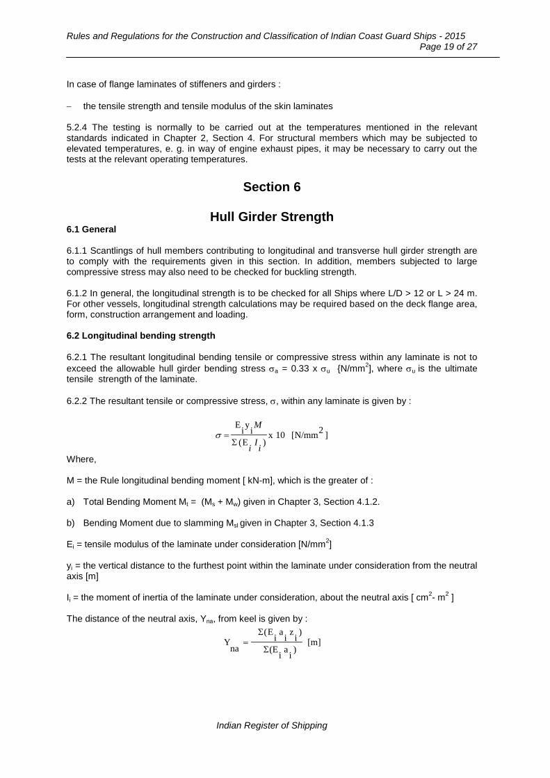
Rules and Regulations for the Construction and Classification of Indian Coast Guard Ships - 2015
Page 19 of 27
In case of flange laminates of stiffeners and girders : − the tensile strength and tensile modulus of the skin laminates 5.2.4 The testing is normally to be carried out at the temperatures mentioned in the relevant standards indicated in Chapter 2, Section 4. For structural members which may be subjected to elevated temperatures, e. g. in way of engine exhaust pipes, it may be necessary to carry out the tests at the relevant operating temperatures.
Section 6
Hull Girder Strength
6.1 General 6.1.1 Scantlings of hull members contributing to longitudinal and transverse hull girder strength are to comply with the requirements given in this section. In addition, members subjected to large compressive stress may also need to be checked for buckling strength. 6.1.2 In general, the longitudinal strength is to be checked for all Ships where L/D > 12 or L > 24 m. For other vessels, longitudinal strength calculations may be required based on the deck flange area, form, construction arrangement and loading. 6.2 Longitudinal bending strength 6.2.1 The resultant longitudinal bending tensile or compressive stress within any laminate is not to exceed the allowable hull girder bending stress σa = 0.33 x σu {N/mm2], where σu is the ultimate tensile strength of the laminate. 6.2.2 The resultant tensile or compressive stress, σ, within any laminate is given by :
]2[N/mm10x)E(
iyiE
iIi
M
Σ=σ
Where, M = the Rule longitudinal bending moment [ kN-m], which is the greater of : a) Total Bending Moment Mt = (Ms + Mw) given in Chapter 3, Section 4.1.2. b) Bending Moment due to slamming Msl given in Chapter 3, Section 4.1.3 Ei = tensile modulus of the laminate under consideration [N/mm2] yi = the vertical distance to the furthest point within the laminate under consideration from the neutral axis [m] Ii = the moment of inertia of the laminate under consideration, about the neutral axis [ cm2- m2 ] The distance of the neutral axis, Yna, from keel is given by :
[m])iai(E
)iziaiE(
naY
Σ
Σ=
Indian Register of Shipping

Chapter 6 : General Hull Requirements for Fibre Composite and Sandwich Constructions
Page 20 of 27
Where, ai, = the cross sectional area of individual laminate [ cm2] zi = the distance to the centre of area of individual laminate from keel [m] 6.3 Calculation of effective sectional properties and longitudinal bending stress 6.3.1 The effective sectional properties of a transverse section are to be calculated using the net area of all continuous longitudinal members after deduction of openings in accordance with Chapter 5, Section 2.3. 6.3.2 In case of sandwich panels, area of only the skin laminates are to be considered, ignoring the core material. 6.4 Openings in longitudinal strength members 6.4.1 The keel plate is normally not to have any openings. In the bilge plate within 0.6L amidships openings are to be avoided as far as practicable. Openings in strength deck are to be kept well clear of Ship’s side and hatch corners. 6.4.2 Circular openings with diameter equal to or more than 0.325 m are to have edge reinforcement. Elliptical openings are to have their major axis in the fore and aft direction. Where the ratio of the major axis to the minor axis is less than 2, the openings are to have edge reinforcement. 6.4.3 Rectangular openings are to have their corners well rounded. Where corners are of circular shape, the radius is not to be less than 20 percent of the breadth of the opening and the edges are to be reinforced. 6.5 Shear Strength 6.5.1 The shear stress, τ, at mid depth at any position along the length is not to exceed the allowable hull shear stress σa = 0.33 x τu {N/mm2], where τu is the ultimate shear strength of the laminate. 6.5.2 The shear stress τ, is to be taken as :
]2[N/mmsA
10Q=τ
Where, Q = the Rule shear force [kN], which is the greater of : a) Total shear force QL = (Qs + Qw) given in Chapter 3, Section 4.1.2. b) Shear force due to slamming Qsl given in Chapter 3, Section 4.1.3. As = net sectional area of laminates of side shell plating and longitudinal bulkheads, if any [cm2]
Indian Register of Shipping

Rules and Regulations for the Construction and Classification of Indian Coast Guard Ships - 2015
Page 21 of 27
Section 7
Sandwich Plate Panels 7.1 General 7.1.1 In this section general requirements for local strength of sandwich panels are given. 7.1.2 The reinforcement of skin laminates is to be containing at least 40% continuous fibres. 7.1.3 In way of keel, stem and knuckles, single skin construction is to be locally adopted with scantlings as specified in Section 8.1. Similarly, in way of rudder tubes and shaft brackets etc; the reinforced areas are generally to be of single skin construction. See Section 4.9 for details. The design in way of attachment of other fittings or equipment is to be such that the load can be transmitted into the structure by bending and not by shear. Suitably reinforced single skin construction is generally to be provided in these areas. The recommended arrangement of reinforcement in way of the transition from sandwich construction to single skin laminate is to be in accordance with Fig. 7.1.3.
T
≅0.4T
≅ 0.6T
≥1.5tc ≥4tc Taper 1:20
tc t2
t1
Fig. 7.1.3 7.2 Sandwich core thickness 7.2.1 The thickness of the sandwich core, tc, is not to be less than :
(i) and ,[mm]a2.
310xb.pcsfct
τ
−=
(ii) [mm]G
210xb.pcdfct
−=
where, fcs = 320 (l/b) + 0.36, with 0.68 ≤ fcs ≤ 1.0 fcd = 0.56 + ln (1000 l/b), with fcd ≤ 1.0 τa = allowable shear stress for the core material, as per Table 7.2.1, [N/mm2]
Indian Register of Shipping
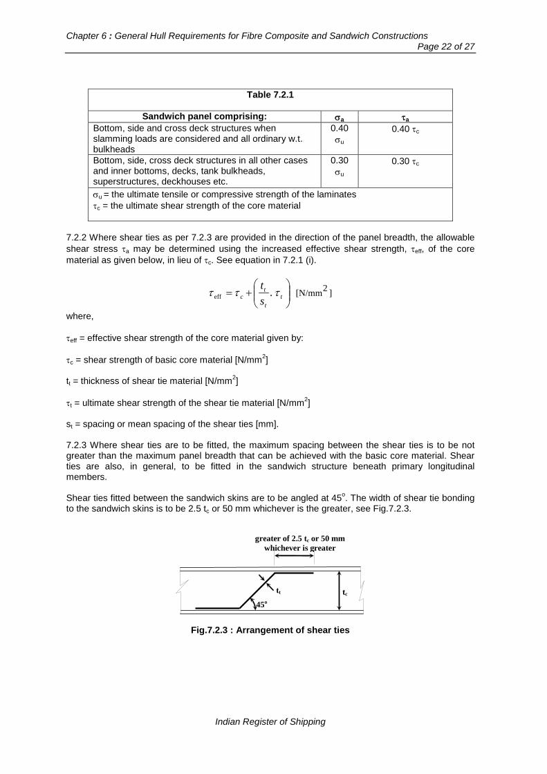
Chapter 6 : General Hull Requirements for Fibre Composite and Sandwich Constructions
Page 22 of 27
Table 7.2.1
Sandwich panel comprising: σa τa
Bottom, side and cross deck structures when slamming loads are considered and all ordinary w.t. bulkheads
0.40 σu
0.40 τc
Bottom, side, cross deck structures in all other cases and inner bottoms, decks, tank bulkheads, superstructures, deckhouses etc.
0.30 σu
0.30 τc
σu = the ultimate tensile or compressive strength of the laminates τc = the ultimate shear strength of the core material
7.2.2 Where shear ties as per 7.2.3 are provided in the direction of the panel breadth, the allowable shear stress τa may be determined using the increased effective shear strength, τeff, of the core material as given below, in lieu of τc. See equation in 7.2.1 (i).
]2[N/mm.eff
+= t
t
tc s
tτττ
where, τeff = effective shear strength of the core material given by: τc = shear strength of basic core material [N/mm2] tt = thickness of shear tie material [N/mm2] τt = ultimate shear strength of the shear tie material [N/mm2] st = spacing or mean spacing of the shear ties [mm]. 7.2.3 Where shear ties are to be fitted, the maximum spacing between the shear ties is to be not greater than the maximum panel breadth that can be achieved with the basic core material. Shear ties are also, in general, to be fitted in the sandwich structure beneath primary longitudinal members. Shear ties fitted between the sandwich skins are to be angled at 45o. The width of shear tie bonding to the sandwich skins is to be 2.5 tc or 50 mm whichever is the greater, see Fig.7.2.3.
greater of 2.5 tc or 50 mm whichever is greater
tc tt
45o
Fig.7.2.3 : Arrangement of shear ties
Indian Register of Shipping
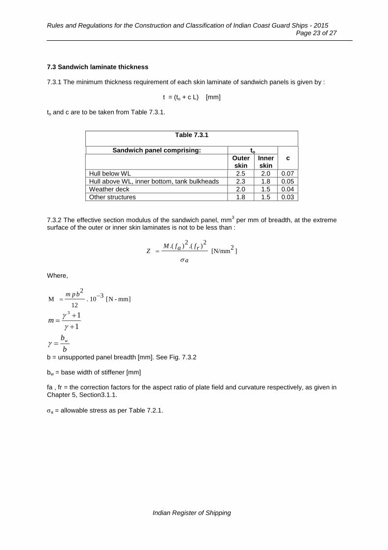
Rules and Regulations for the Construction and Classification of Indian Coast Guard Ships - 2015
Page 23 of 27
7.3 Sandwich laminate thickness 7.3.1 The minimum thickness requirement of each skin laminate of sandwich panels is given by :
t = (to + c L) [mm] to and c are to be taken from Table 7.3.1.
Table 7.3.1
Sandwich panel comprising: to c Outer
skin Inner skin
Hull below WL 2.5 2.0 0.07 Hull above WL, inner bottom, tank bulkheads 2.3 1.8 0.05 Weather deck 2.0 1.5 0.04 Other structures 1.8 1.5 0.03
7.3.2 The effective section modulus of the sandwich panel, mm3 per mm of breadth, at the extreme surface of the outer or inner skin laminates is not to be less than :
]2[N/mm2).(2).(
σ a
rfafMZ =
Where,
]mm-N[310.12
2M −=
bpm
113
++
=γ
γm
bbw=γ
b = unsupported panel breadth [mm]. See Fig. 7.3.2 bw = base width of stiffener [mm] fa , fr = the correction factors for the aspect ratio of plate field and curvature respectively, as given in Chapter 5, Section3.1.1. σa = allowable stress as per Table 7.2.1.
Indian Register of Shipping
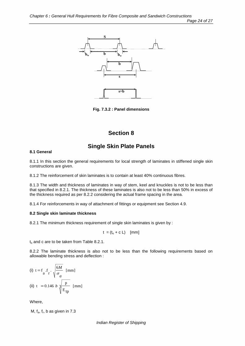
Chapter 6 : General Hull Requirements for Fibre Composite and Sandwich Constructions
Page 24 of 27
S
b bw bw
b
s
s=b
Fig. 7.3.2 : Panel dimensions
Section 8
Single Skin Plate Panels 8.1 General 8.1.1 In this section the general requirements for local strength of laminates in stiffened single skin constructions are given. 8.1.2 The reinforcement of skin laminates is to contain at least 40% continuous fibres. 8.1.3 The width and thickness of laminates in way of stem, keel and knuckles is not to be less than that specified in 8.2.1. The thickness of these laminates is also not to be less than 50% in excess of the thickness required as per 8.2.2 considering the actual frame spacing in the area. 8.1.4 For reinforcements in way of attachment of fittings or equipment see Section 4.9. 8.2 Single skin laminate thickness 8.2.1 The minimum thickness requirement of single skin laminates is given by :
t = (to + c L) [mm] to and c are to be taken from Table 8.2.1. 8.2.2 The laminate thickness is also not to be less than the following requirements based on allowable bending stress and deflection :
(i) ]mm[6
.r
.fa
f t a
Mσ
=
(ii) ]mm[3tpE
p0.146 t b=
Where, M, fa, fr, b as given in 7.3
Indian Register of Shipping

Rules and Regulations for the Construction and Classification of Indian Coast Guard Ships - 2015
Page 25 of 27
σa = allowable stress as per Table 8.2.2 Etp = tensile modulus of plate laminate [N/mm2].
Table 8.2.1
Single skin laminate comprising: to c Stem and keel, for a distance of (100+8L) mm on either side of centre line
9.0
0.10
Chine and transom corners, for a distance of (10L) mm on either side of the corner
7.0
0.06
Hull below WL 5.0 0.10 Hull above WL, inner bottom, tank bulkheads 5.0 0.05 Weather deck 4.5 0.05 Other structures 3.5 0.05
Table 8.2.2
Single skin laminate comprising: σa Bottom, side and cross deck structures when slamming loads are considered and all ordinary w.t. bulkheads
0.40 σu
Bottom, side, cross deck structures in all other cases and inner bottoms, decks, tank bulkheads, superstructures, deckhouses etc.
0.30 σu
σu = the ultimate tensile or compressive strength of the laminates
Section 9
Stiffeners, Primary Girders and Pillars
9.1 Applications 9.1.1 In this section general requirements for local strength of stiffeners and primary girders ( i.e. longitudinal and transverse girders, web frames etc.) and pillars based on the lateral pressure on plating they support are given. 9.2 Strength requirements of stiffeners and girders 9.2.1 The required section modulus of each stiffener and girder, based on the lateral pressure is given by:
]3cm[2l
Zam
ps
σ=
Indian Register of Shipping
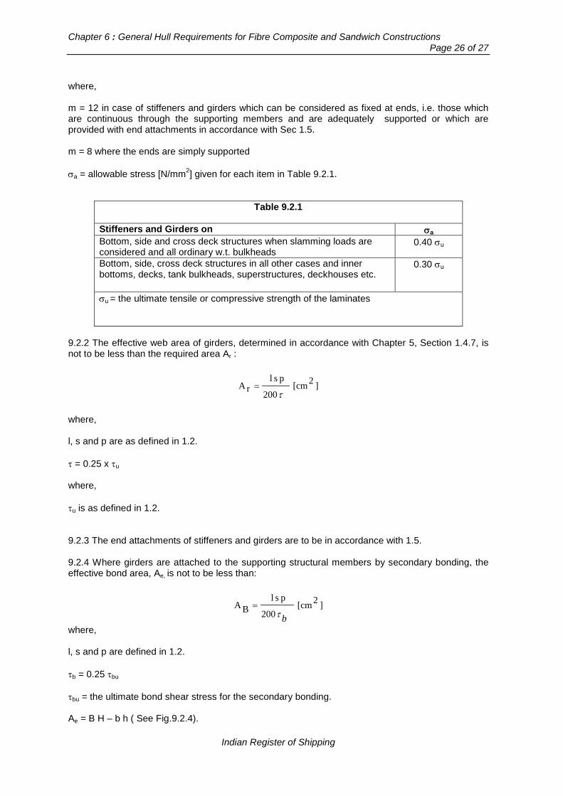
Chapter 6 : General Hull Requirements for Fibre Composite and Sandwich Constructions
Page 26 of 27
where, m = 12 in case of stiffeners and girders which can be considered as fixed at ends, i.e. those which are continuous through the supporting members and are adequately supported or which are provided with end attachments in accordance with Sec 1.5. m = 8 where the ends are simply supported σa = allowable stress [N/mm2] given for each item in Table 9.2.1.
Table 9.2.1
Stiffeners and Girders on σa Bottom, side and cross deck structures when slamming loads are considered and all ordinary w.t. bulkheads
0.40 σu
Bottom, side, cross deck structures in all other cases and inner bottoms, decks, tank bulkheads, superstructures, deckhouses etc.
0.30 σu
σu = the ultimate tensile or compressive strength of the laminates
9.2.2 The effective web area of girders, determined in accordance with Chapter 5, Section 1.4.7, is not to be less than the required area Ar :
]2[cm200
pslrA
τ=
where, l, s and p are as defined in 1.2. τ = 0.25 x τu where, τu is as defined in 1.2. 9.2.3 The end attachments of stiffeners and girders are to be in accordance with 1.5. 9.2.4 Where girders are attached to the supporting structural members by secondary bonding, the effective bond area, Ae, is not to be less than:
]2[cm200
pslBA
bτ=
where, l, s and p are defined in 1.2. τb = 0.25 τbu τbu = the ultimate bond shear stress for the secondary bonding. Ae = B H – b h ( See Fig.9.2.4).
Indian Register of Shipping
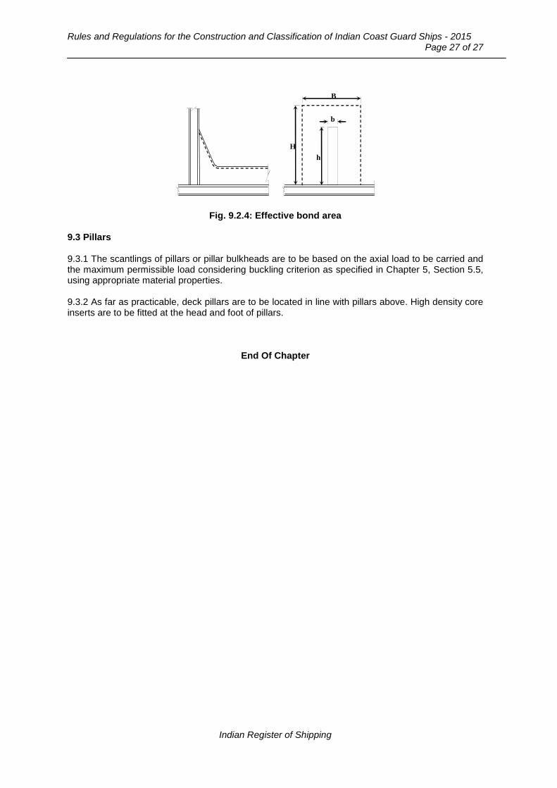
Rules and Regulations for the Construction and Classification of Indian Coast Guard Ships - 2015
Page 27 of 27
H h
b
B
Fig. 9.2.4: Effective bond area 9.3 Pillars 9.3.1 The scantlings of pillars or pillar bulkheads are to be based on the axial load to be carried and the maximum permissible load considering buckling criterion as specified in Chapter 5, Section 5.5, using appropriate material properties. 9.3.2 As far as practicable, deck pillars are to be located in line with pillars above. High density core inserts are to be fitted at the head and foot of pillars.
End Of Chapter
Indian Register of Shipping
Rules and Regulations for the Construction and Classification of Indian Coast Guard Ships - 2015
Page 1 of 10
Chapter 7
Hull Appendages, Rudders and Steering Arrangement
Contents Section
1 General Requirements
2 Bar Keel, Stem and Stern Frames
3 Shaft Brackets
4 Rudders
5 Fin Stabilizers
6 Steering Gear Systems
7 Water Jet Installations
Section 1
General Requirements
1.1 Scope 1.1.1 This chapter applies to all the Ship types detailed in the Rules. Requirements are given for stem, stern frame, shaft brackets, rudders, stabilizers and steering gears. 1.1.2 Further, the requirements include structural strength of hull foundations of above items and appended propulsion units such as water jets. 1.1.3 The details of other appendages e.g. hydrofoils, wings etc. will be specially considered. 1.2 Materials 1.2.1 All plates and sections, castings and forgings used in the constructions are to be tested and approved in accordance with the requirements of Part 2 of the ‘Rules and Regulations for the Construction and Classification of Steel Ships’. 1.2.2 Use of other materials not covered above will be individually considered.
Indian Register of Shipping
Chapter 7 : Hull Appendages, Rudders and Steering Arrangement
Page 2 of 10
Section 2
Bar Keel, Stem and Stern Frames 2.1 General 2.1.1 Bar keel, stem and stern frames are to be designed such that they are effectively integrated into the ship's structure. 2.1.2 It is recommended that the after body of the ship be so shaped as to ensure adequate flow of water to the propeller so as to prevent uneven formation of eddies, as far as possible. 2.1.3 The scantlings are indicated based on normal mild steel as per Part 2 of the ‘Rules and Regulations for the Construction and Classification of Steel Ships’. Aluminium stern frames and stems will be specially considered based on the proposed material grades. 2.2 Bar keel and stem 2.2.1 Details and scantlings of bar keel and stem are to be as per Section 2 and Section 3 respectively of Part 3, Chapter 6 of the ‘Rules and Regulations for the Construction and Classification of Steel Ships’. 2.2.2 The thickness of the plate stem is not to be lower than the rule side shell plate thickness in way. However, the thickness ‘t’ of the plate stem below the summer load water line need not be more than:
t = (0.1L + 3) k1/2
2.2.3 The thickness of the plate stem may be gradually reduced to that of the side shell at the stem head. 2.2.4 The plate stems are to be supported by horizontal diaphragms spaced not more than 1.0 [m] apart. When the stem plate radius is large, a centerline stiffener or web is to be provided. 2.3 Stern frames 2.3.1 For a moderately cavitating propeller the minimum values of propeller-hull clearances may be as per Part 3, Chapter 6, Section 4 of the ‘Rules and Regulations for the Construction and Classification of Steel Ships’. For propellers that are heavily loaded, the propeller-hull clearances will be specially considered individually based on detailed analysis. 2.3.2 The scantlings and details of the stern frames are to be as per Part 3, Chapter 6, Section 4 of the Rules as mentioned in 2.3.1 above. 2.3.3 The scantlings and details of rudder posts are to be as per Part 3, Chapter 6 of the Rules mentioned in 2.3.1 above. 2.4 Sole piece 2.4.1 The details and scantlings of sole-pieces if fitted are to be as per Part 3, Chapter 6, Section 4 of the Rules mentioned in 2.3.1 above.
Indian Register of Shipping

Rules and Regulations for the Construction and Classification of Indian Coast Guard Ships - 2015
Page 3 of 10
Section 3
Shaft Brackets
3.1 Details of shaft bracket struts and reinforcements in way are to be as per Part 3, Chapter 6, Section 4 of the Rules as mentioned in 2.3.1 above. 3.2 For the shaft and the shaft bracket boss made of the same material the length and thickness [mm] of the shaft bracket boss are to be not less than (4dp) and (dp/4), respectively, where dp is the tail shaft diameter [mm]. For shaft and shaft bracket boss made of different materials dp [mm] is to be based on bracket boss material. For calculating dp see Chapter 12, Section 2.
Section 4
Rudders
4.1 The details and scantlings of rudder blade, rudder stock, pintles and rudder couplings are to be as per Part 3, Chapter 14 of the ‘Rules and Regulations for the Construction and Classification of Steel Ships’.
Section 5
Fin Stabilizers
5.1 General 5.1.1 The general structure of the fin stabilizer is to comply with the rule requirement for rudders. 5.1.2 Fin stabilizers are to be contained within a watertight compartment. For non-retractable fin stabilizers, the forward and aft bulkheads of the water tight compartment are to be arranged not less than one root chord length from the center line of the stabilizer shaft. For retractable type stabilizers, the forward and aft bulkheads of the water tight compartment are to be arranged not less than the total length of the stabilizer (from the extreme end of the shaft to the tip of the stabilizer fin) from the center of the stabilizer shaft. 5.1.3 In general, the stabilizer fins should not extent beyond the design water line breadth and design depth. However, in the case of retractable fins, alternate arrangements may be considered, subject to operational restrictions, when permitted by the Indian Coast Guard 5.1.4 The stabilizer machinery and surrounding structure are to be adequately stiffened and supported. When cyclic loadings are expected, the maximum stresses are not to exceed 39 [N/mm2] in the case of mild steel. When other materials are used the limiting stress values shall be specially considered. 5.1.5 The shell plating in way of the retractable stabilizers are to comply with the requirements in 5.1.4. The thickness of the insert plate should be at least 50% more than the thickness of the bottom shell in way of the opening. The extent of the insert plate in way of the opening is to be such that it covers 125 percent of the operational profile of the stabilizer fin in all directions. 5.1.6 The scantlings of the internal watertight bulkheads and stiffening are not to be less than the scantlings for double bottom structures in way and as specified by the manufacturer of the stabilizer
Indian Register of Shipping

Chapter 7 : Hull Appendages, Rudders and Steering Arrangement
Page 4 of 10
system. The box into which the stabilizers are fitted are to be thicker than the adjacent shell plating at least by 2 mm. Stiffening of the structure should be to the same standard applicable to adjacent ships structures. 5.1.7 When retractable fin stabilizers are fitted, position indicators are to be provided at the Navigation Bridge, emergency steering positions and local control stations. 5.1.8 The scantlings of the fins, stocks, supporting structures and attachments are to be directly calculated when the fins are of novel design, high aspect ratio, or when the ships speed is more than 45 knots. 5.2 Design loads 5.2.1 The fin force FF [kN] is to be calculated using the maximum speed of the vessel in ahead condition and using the maximum astern speed, not less than 50 % of the ahead speed, in the astern condition. The details of the calculations are to be submitted. Forces due to the self weight of the fin are also to be considered. 5.2.2 The fin torque QF in ahead and astern conditions may be determined from the following formula:
QF = FF x r [kNm] where
FF = fin force as defined at 5.2.1.
r is the mean distance of center of pressure from the leading edge [m] to be calculated similar to that for rudders .
Torque due to the self weight of the fin is also to be considered.
5.2.3 For conventional fins, the fin bending moment MF may be determined as
MF = FF x YG kNm,
Where: FF is as defined in 5.2.1. YG is the distance of the centroid of the area of the fin from mid length of the main bearing of the fin stock, in metres.
Bending moment due to the self weight of the fin is also to be considered. 5.3 Fin stabilizer construction 5.3.1 Diameter of the fin stocks when obtained by direct calculation are normally to give an equivalent stress σ e not exceeding 118/k [N/mm2] i.e.
][N/mmk/1183 222 ≤+= te τσσ
where,
σ is the bending stress in [N/mm2],
τt is the torsional shear stress in [N/mm2]. This requirement is regardless of the liners; and both ahead and astern conditions are to be considered.
Indian Register of Shipping

Rules and Regulations for the Construction and Classification of Indian Coast Guard Ships - 2015
Page 5 of 10
5.3.2 Fin stock diameter in way of the tiller, du ,is given by du = 4.2 3√ (QF . k) [mm], where QF is the fin torque in appropriate condition. 5.3.3 Fin stock diameter ,d, at any other section is given by: d = du 6√ { 1 + (4/3) (MF/QF)2 } [mm], where QF and MF are Fin torque and bending moment, [kNm], in appropriate condition considering the self weight of the fin also. 5.3.4 Sudden changes of sections and sharp corners are to be avoided in the case of the stocks. All corners and fillets are to be smooth and radiused to avoid stress concentrations. 5.3.5 Bearing pressures are to be as per the requirements for rudders. 5.3.6 Design and construction of the stabilizer fins are to be as per the requirements of rudder blades specified at 4.1 using forces, torques and moments applicable to the fins in appropriate ahead / astern conditions.
Section 6
Steering Gear Systems
6.1 Scope 6.1.1 The requirements of this chapter apply to the design and construction of Directional Control systems. A Directional Control System includes all steering devices, all mechanical, electrical and hydraulic linkages, all power devices, including manual devices, all controls and all actuating systems. Steering may be achieved by means of air or water rudders, foils, flaps, steerable propellers or jets, yaw control ports or transverse thrusters, differential propulsive thrust, variable geometry of the Ship or its lift system components or by a combination of these devices. 6.2 General 6.2.1 Ship should be provided with means for directional control of adequate strength and suitable design to enable the Ship’s heading and direction of travel to be effectively controlled to the maximum extent possible in the prevailing conditions and Ship spaced without undue physical effort at all speeds and in all conditions for which the Ship is to be certified. 6.2.2 Attention is drawn to the possibility of interaction between directional control system and stabilization systems. Where such interaction occurs or where dual purpose components are fitted requirement of the independent circuits of stabilization system and of controllability to be complied with. 6.3 Definitions 6.3.1 Part 4, Chapter 6 of the ‘Rules and Regulations for the Construction and Classification of Steel Ships’ .may be referred for all applicable definitions, installation and location requirements of steering gear compartment.. 6.4 Plans and documents 6.4.1 Plans and documents of the steering gear system to be submitted are as follows:
Indian Register of Shipping

Chapter 7 : Hull Appendages, Rudders and Steering Arrangement
Page 6 of 10
Plans
a) General arrangements of the main and auxiliary steering gears, and of the steering gear compartment.
b) Assembly of upper rudder stock, tiller, tie rod, rudder actuators, etc. as applicable.
c) Construction details of all torque transmitting components of steering gear such as tiller,
tiller pin, tiller/rudder stock interference fit mechanism, tie rod, rudder actuator, etc. including bill of materials, welding procedures, non-destructive testing, as applicable.
d) Schematic hydraulic piping diagram, incorporating hydraulic logic diagram and including bill
of materials, typical pipe to pipe joint details, pipe to valve joint details, pipe to equipment joint details, pressure rating of valves and pipe fittings and pressure relief valve settings.
e) Steering gear control system, incorporating schematic electrical control logic diagram,
instrumentation, alarm devices, etc. including bill of materials.
f) Electrical power supply to power units to steering gear control, including schematic diagram of motor controlled feeder cables, feeder cable electrical protection.
Documents − Rated torque of main steering gear. − Calculations of torque-transmitting components − such as tiller, tie rod, rudder actuator, etc. 6.5 Materials 6.5.1 All the steering gear components and the rudder stock are to be of sound and reliable construction to the Surveyor's satisfaction. 6.5.2 All components transmitting mechanical forces to the rudder stock are to be tested according to the requirements of Part 2 of the ‘Rules and Regulations for the Construction and Classification of Steel Ships’. 6.5.3 Ram; cylinders; pressure housing of rotary vane type actuators; hydraulic power piping; valves; flanges and fittings; and all steering gear components transmitting mechanical forces to the rudder stock (such as tillers, quadrants, or similar components) are to be of steel or other approved ductile material, duly tested in accordance with the requirements of Part 2 of the ‘Rules and Regulations for the Construction and Classification of Steel Ships’. In general, such material is not to have an elongation of less than 12 per cent nor a tensile strength in excess of 650 [N/mm2]. The use of ductile (nodular) iron castings will be acceptable provided the material has an elongation of not less than 12 per cent. 6.6 Rudder, rudder stock, vanes, tiller and quadrant 6.6.1 Details and scantlings of rudder and rudder stock are to be as per Section 4 above. Maximum permissible jumping clearances and rudder bush clearances are to be clearly mentioned in the drawings and same is to be also clearly indicated in the manuals. 6.6.2 Details and scantlings of vanes, tiller and quadrants are to be as per Part 4, Chapter 6 of the ‘Rules and Regulations for the Construction and Classification of Steel Ships’.
Indian Register of Shipping
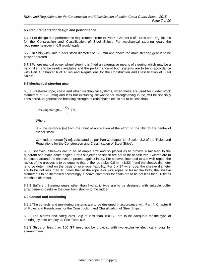
Rules and Regulations for the Construction and Classification of Indian Coast Guard Ships - 2015
Page 7 of 10
6.7 Requirements for design and performance 6.7.1 For design and performance requirements refer to Part 4, Chapter 6 of ‘Rules and Regulations for the Construction and Classification of Steel Ships’. For mechanical steering gear, the requirements given in 6.8 would apply. 6.7.2 In Ship with Rule rudder stock diameter of 120 mm and above the main steering gear is to be power operated. 6.7.3 Where manual power wheel steering is fitted an alternative means of steering which may be a hand tiller is to be readily available and the performance of both systems are to be in accordance with Part 4, Chapter 6 of ‘Rules and Regulations for the Construction and Classification of Steel Ships’. 6.8 Mechanical steering gear 6.8.1 Steel-wire rope, chain and other mechanical systems, when these are used for rudder stock diameters of 120 [mm] and less but excluding allowance for strengthening in ice, will be specially considered. In general the breaking strength of rods/chains etc. is not to be less than :
][R
rQ 6 strength Breaking N=
Where,
R = the distance [m] from the point of application of the effort on the tiller to the centre of rudder stock.
Qr = rudder torque [N-m], calculated as per Part 3, chapter 14, Section 3.2 of the ‘Rules and Regulations for the Construction and Classification of Steel Ships’.
6.8.2 Sheaves: Sheaves are to be of ample size and so placed as to provide a fair lead to the quadrant and avoid acute angles. Parts subjected to shock are not to be of cast iron. Guards are to be placed around the sheaves to protect against injury. For sheaves intended to use with ropes, the radius of the grooves is to be equal to that of the rope plus 0.8 mm (1/32in) and the sheave diameter is to be determined on the basis of wire rope flexibility. For 5 x 37 wire rope, the sheave diameter are to be not less than 18 times that of the rope. For wire ropes of lesser flexibility, the sheave diameter is to be increased accordingly. Sheave diameters for chain are to be not less than 30 times the chain diameter. 6.8.3 Buffers : Steering gears other than hydraulic type are to be designed with suitable buffer arrangement to relieve the gear from shocks to the rudder. 6.9 Control and monitoring 6.9.1 The controls and monitoring systems are to be designed in accordance with Part 4, Chapter 6 of ‘Rules and Regulations for the Construction and Classification of Steel Ships’. 6.9.2 The alarms and safeguards Ship of less than 150 GT are to be adequate for the type of steering system employed. See Table 6.9 6.9.3 Ships of less than 150 GT need not be provided with two exclusive electrical circuits for steering gear.
Indian Register of Shipping
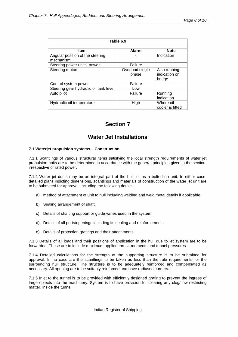
Chapter 7 : Hull Appendages, Rudders and Steering Arrangement
Page 8 of 10
Table 6.9
Item Alarm Note
Angular position of the steering mechanism
- Indication
Steering power units, power Failure - Steering motors Overload single
phase Also running indication on bridge
Control system power Failure - Steering gear hydraulic oil tank level Low Auto pilot Failure Running
indication Hydraulic oil temperature High Where oil
cooler is fitted
Section 7
Water Jet Installations
7.1 Waterjet propulsion systems – Construction 7.1.1 Scantlings of various structural items satisfying the local strength requirements of water jet propulsion units are to be determined in accordance with the general principles given in the section, irrespective of rated power. 7.1.2 Water jet ducts may be an integral part of the hull, or as a bolted on unit. In either case, detailed plans indicting dimensions, scantlings and materials of construction of the water jet unit are to be submitted for approval, including the following details:
a) method of attachment of unit to hull including welding and weld metal details if applicable
b) Sealing arrangement of shaft
c) Details of shafting support or guide vanes used in the system.
d) Details of all ports/openings including its sealing and reinforcements
e) Details of protection gratings and their attachments 7.1.3 Details of all loads and their positions of application in the hull due to jet system are to be forwarded. These are to include maximum applied thrust, moments and tunnel pressures. 7.1.4 Detailed calculations for the strength of the supporting structure is to be submitted for approval. In no case are the scantlings to be taken as less than the rule requirements for the surrounding hull structure. The structure is to be adequately reinforced and compensated as necessary. All opening are to be suitably reinforced and have radiused corners. 7.1.5 Inlet to the tunnel is to be provided with efficiently designed grating to prevent the ingress of large objects into the machinery. System is to have provision for clearing any clog/flow restricting matter, inside the tunnel.
Indian Register of Shipping

Rules and Regulations for the Construction and Classification of Indian Coast Guard Ships - 2015
Page 9 of 10
7.1.6 Water jet unit(s) having a total rated power more than 500 [kW] are to be contained within their own watertight compartment. Other arrangements for maintaining watertight integrity would be specially considered depending on the size and installation layout. 7.1.7 For details of machinery requirements, see Chapter 12. 7.2 Waterjet systems – Installation 7.2.1 All units are to be installed in accordance with the manufacturer’s instructions. Integral jet ducts to be constructed in accordance with the manufacturer’s requirements and as per relevant approved plans required by Section 6.1.2. 7.2.2 Where the load is transmitted to the transom and/or bottom shell, the thickness of plating in way is to be increased by 50 percent over calculated rule thickness; however, increase in thickness is not to be less than 8 [mm]. Such reinforcement is to extend beyond the adjacent main supporting stiffeners. 7.2.3 For “bolted in” units, hull receiving rings are to be of a material compatible with the hull. All welding details are to be to the satisfaction of the attending Surveyors. 7.2.4 Bolt sizes and spacings are to be finalized in consultation with the system manufacturer and are to be of suitable marine grade, insulated as appropriate and locked by suitable means. 7.2.5 Where studs are proposed, the remaining thickness of plating below the depth of blind tap is to be not less than the rule plating thickness in way plus 2 [mm]. Bottom of all blind taps are to be free of sharp corners. 7.2.6 Use of approved alignment resins may be considered, where accurate seating and laying surfaces are required. Details are to be submitted for consideration alongwith tightening torque and bearing loads. 7.2.7 Where complex installations are proposed, an approved FE model analysis results are to be submitted in lieu of calculations from the first principle. 7.3 Design loads 7.3.1 Maximum load due to the installation(s) including the following loads are normally to be considered: − Crash stop − Maximum reversing load, from 10 kn − Forward speed − Maximum steering load − Waterjet unit weight with dynamic load factors as per the rules i.e. unit acting as a cantilever
during vessel pitching − High cycle loads from impeller pulses, if available from the system manufacturer. Design forces/moments and information regarding weights are to be specified by the manufacturer of the waterjet. 7.4 Allowable stresses 7.4.1 The maximum allowable stresses for the duct and hull supporting structures are as follows: − Normal stress : σ = 110/k [N/mm2]
− Shear stress : τ = 50/k [N/mm2]
Indian Register of Shipping

Chapter 7 : Hull Appendages, Rudders and Steering Arrangement
Page 10 of 10
Where, k for steel is to be as per Chapter 2, Section 2 k for aluminium is to be as per Chapter 2, Section 3, and For FRP structure, maximum allowable stresses for the duct and hull supporting structures are as follows:
Normal stress : σ = 0.2 σu [N/mm2]
Shear stress : τ = 0.2 τu [N/mm2]
where,
σu = ultimate tensile strength of the plate laminate [N/mm2]
τu = ultimate shear strength of the plate laminate [N/mm2]. 7.4.2 For the steering, reversing and cantilever bending, the maximum allowable stresses are to be based on fatigue life considerations. The number cycles for each load case is to be based on the expected operational time during 20 years lifetime of the Ship and normally not to be taken less than: − 105 cycles for reversing loads − 106 cycles for steering loads, and − 107 cycles for pitching loads.
End Of Chapter
Indian Register of Shipping
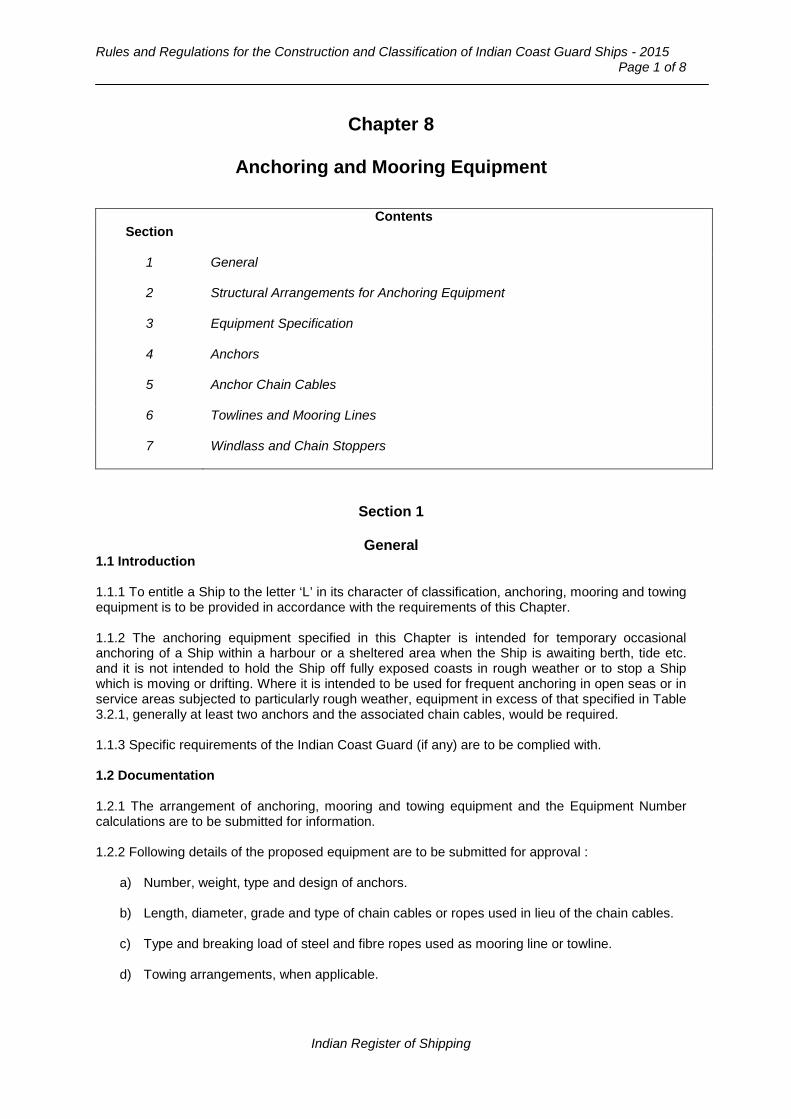
Rules and Regulations for the Construction and Classification of Indian Coast Guard Ships - 2015
Page 1 of 8
Chapter 8
Anchoring and Mooring Equipment
Contents Section
1 General
2 Structural Arrangements for Anchoring Equipment
3 Equipment Specification
4 Anchors
5 Anchor Chain Cables
6 Towlines and Mooring Lines
7 Windlass and Chain Stoppers
Section 1
General 1.1 Introduction 1.1.1 To entitle a Ship to the letter ‘L’ in its character of classification, anchoring, mooring and towing equipment is to be provided in accordance with the requirements of this Chapter. 1.1.2 The anchoring equipment specified in this Chapter is intended for temporary occasional anchoring of a Ship within a harbour or a sheltered area when the Ship is awaiting berth, tide etc. and it is not intended to hold the Ship off fully exposed coasts in rough weather or to stop a Ship which is moving or drifting. Where it is intended to be used for frequent anchoring in open seas or in service areas subjected to particularly rough weather, equipment in excess of that specified in Table 3.2.1, generally at least two anchors and the associated chain cables, would be required. 1.1.3 Specific requirements of the Indian Coast Guard (if any) are to be complied with. 1.2 Documentation 1.2.1 The arrangement of anchoring, mooring and towing equipment and the Equipment Number calculations are to be submitted for information. 1.2.2 Following details of the proposed equipment are to be submitted for approval :
a) Number, weight, type and design of anchors.
b) Length, diameter, grade and type of chain cables or ropes used in lieu of the chain cables.
c) Type and breaking load of steel and fibre ropes used as mooring line or towline.
d) Towing arrangements, when applicable.
Indian Register of Shipping

Chapter 8 : Anchoring and Mooring Equipment
Page 2 of 8
Section 2
Structural Arrangements for Anchoring Equipment 2.1 General 2.1.1 The anchors are normally to be housed in hawse pipes and anchor pockets of adequate size, scantlings and suitable form to prevent movement of anchor and chain due to wave action. Other suitable arrangements for housing of anchors may be considered. The arrangements are to provide an easy lead of chain cable from windlass to the anchors. Upon release of the brake, the anchors are to immediately start falling by their own weight. Substantial chafing lips are to be provided at shell and deck. These are to have sufficiently large and radiused faces to minimise the probability of cable links being subjected to large bending stresses. Alternatively, roller fairleads of suitable design may be fitted. 2.1.2 The shell plating and framing in way of the hawse pipes are to be reinforced as necessary. 2.1.3 On ships provided with a bulbous bow or a wave piercing bow and where it is not possible to obtain ample clearance between shell plating and anchors during anchor handling, adequate local reinforcements are to be provided in areas likely to be damaged by anchors or chain cables. 2.1.4 The chain locker is to have adequate capacity and depth to provide an easy direct lead for the cable into the chain pipes, when the cable is fully stowed. The chain pipes are to be of suitable size and provided with chafing lips. The port and starboard cables are to have separate spaces. Provisions are to be made to minimize the ingress of water to the chain locker in bad weather. The chain lockers fitted abaft of the collision bulkhead are to be watertight and the space is to be efficiently drained. Provisions are to be made for securing the inboard ends of the chains to the structure. The strength of this attachment should be between 15 per cent to 30 per cent of the breaking strength of the chain cable. It is recommended that suitable arrangements be provided so that in an emergency the chain can be readily made to slip from an accessible position outside the chain locker. 2.1.5 The windlass and chain stoppers are to be efficiently bedded and secured to deck. The thickness of deck plating is to be increased in way of the windlass and chain stoppers and adequate stiffening underneath is to be provided.
Section 3
Equipment Specification
3.1 The equipment number, EN, on which the requirements of equipment are based is to be calculated as follows : -
EN = K.ENc
Where,
[ ] AihibaBENc 1.0).(23/2)( +Σ++∆Σ=
∆i = moulded displacement [t] of the ith hull, corresponding to the design water line. For monohull Ships i = 1 and ∆i = ∆.
a = distance [m] from design waterline amidships to the upper deck at side
Indian Register of Shipping
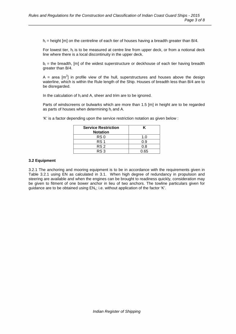
Rules and Regulations for the Construction and Classification of Indian Coast Guard Ships - 2015
Page 3 of 8
hi = height [m] on the centreline of each tier of houses having a breadth greater than B/4.
For lowest tier, hi is to be measured at centre line from upper deck, or from a notional deck line where there is a local discontinuity in the upper deck.
bi = the breadth, [m] of the widest superstructure or deckhouse of each tier having breadth greater than B/4.
A = area [m2] in profile view of the hull, superstructures and houses above the design waterline, which is within the Rule length of the Ship. Houses of breadth less than B/4 are to be disregarded.
In the calculation of hi and A, sheer and trim are to be ignored.
Parts of windscreens or bulwarks which are more than 1.5 [m] in height are to be regarded as parts of houses when determining hi and A.
‘K’ is a factor depending upon the service restriction notation as given below :
Service Restriction
Notation K
RS 0 1.0 RS 1 0.9 RS 2 0.8 RS 3 0.65
3.2 Equipment 3.2.1 The anchoring and mooring equipment is to be in accordance with the requirements given in Table 3.2.1 using EN as calculated in 3.1. When high degree of redundancy in propulsion and steering are available and when the engines can be brought to readiness quickly, consideration may be given to fitment of one bower anchor in lieu of two anchors. The towline particulars given for guidance are to be obtained using ENc; i.e. without application of the factor ‘K’.
Indian Register of Shipping
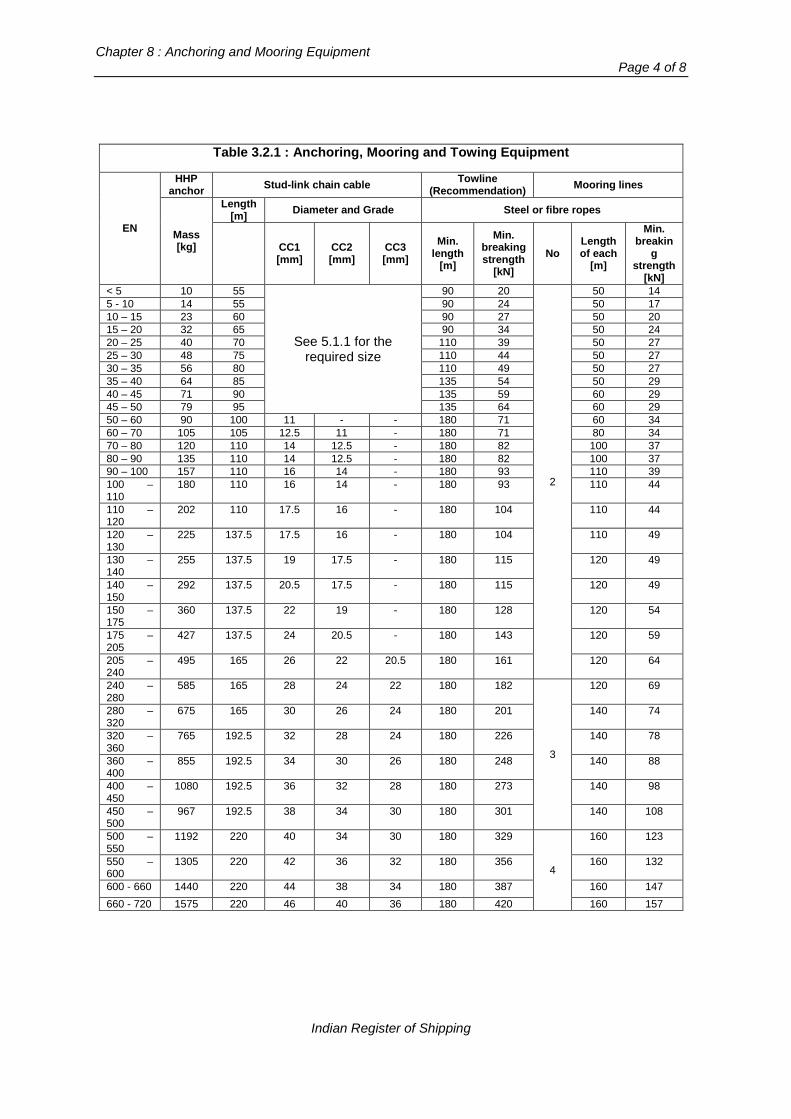
Chapter 8 : Anchoring and Mooring Equipment
Page 4 of 8
Table 3.2.1 : Anchoring, Mooring and Towing Equipment
EN
HHP anchor Stud-link chain cable Towline
(Recommendation) Mooring lines
Mass [kg]
Length [m] Diameter and Grade Steel or fibre ropes
CC1 [mm]
CC2 [mm]
CC3 [mm]
Min. length
[m]
Min. breaking strength
[kN] No
Length of each
[m]
Min. breakin
g strength
[kN] < 5 10 55
See 5.1.1 for the required size
90 20
2
50 14 5 - 10 14 55 90 24 50 17 10 – 15 23 60 90 27 50 20 15 – 20 32 65 90 34 50 24 20 – 25 40 70 110 39 50 27 25 – 30 48 75 110 44 50 27 30 – 35 56 80 110 49 50 27 35 – 40 64 85 135 54 50 29 40 – 45 71 90 135 59 60 29 45 – 50 79 95 135 64 60 29 50 – 60 90 100 11 - - 180 71 60 34 60 – 70 105 105 12.5 11 - 180 71 80 34 70 – 80 120 110 14 12.5 - 180 82 100 37 80 – 90 135 110 14 12.5 - 180 82 100 37 90 – 100 157 110 16 14 - 180 93 110 39 100 – 110
180 110 16 14 - 180 93 110 44
110 – 120
202 110 17.5 16 - 180 104 110 44
120 – 130
225 137.5 17.5 16 - 180 104 110 49
130 – 140
255 137.5 19 17.5 - 180 115 120 49
140 – 150
292 137.5 20.5 17.5 - 180 115 120 49
150 – 175
360 137.5 22 19 - 180 128 120 54
175 – 205
427 137.5 24 20.5 - 180 143 120 59
205 – 240
495 165 26 22 20.5 180 161 120 64
240 – 280
585 165 28 24 22 180 182
3
120 69
280 – 320
675 165 30 26 24 180 201 140 74
320 – 360
765 192.5 32 28 24 180 226 140 78
360 – 400
855 192.5 34 30 26 180 248 140 88
400 – 450
1080 192.5 36 32 28 180 273 140 98
450 – 500
967 192.5 38 34 30 180 301 140 108
500 – 550
1192 220 40 34 30 180 329
4
160 123
550 – 600
1305 220 42 36 32 180 356 160 132
600 - 660 1440 220 44 38 34 180 387 160 147 660 - 720 1575 220 46 40 36 180 420 160 157
Indian Register of Shipping

Rules and Regulations for the Construction and Classification of Indian Coast Guard Ships - 2015
Page 5 of 8
Section 4
Anchors 4.1 General 4.1.1 Anchors are to be of an approved design. 4.1.2 The anchor mass given in Table 3.2.1 is based on the use of H.H.P (high holding power) type anchors. 4.1.3 When ordinary holding power anchors are used as bower anchors, the tabular mass is to be increased by 33%. 4.1.4 When anchors of a design approved for the designation SHHP (Super High Hold Power) are used as bower anchors the tabular mass may be reduced by 33%. 4.1.5 The actual mass of each anchor may vary by +7% to –3% per cent of the tabular mass. 4.1.6 Anchor shackles are to be of a design and material suitable to the service for which the anchor is intended. 4.2 HHP (SHHP) anchors 4.2.1 Designs of HHP and SHHP anchors are to be approved for the designation in accordance with Part 3, Chapter 15 of the ‘Rules for the Construction and Classification of Steel Ships’. 4.3 Manufacture and testing 4.3.1 Anchors and anchor shackles are to be manufactured and tested in accordance with the requirements of Part 2, Chapter 10 of the ‘Rules for the Construction and Classification of Steel Ships’.
Section 5
Anchor Chain Cables
5.1 General 5.1.1 Anchor chain cables are to be as required by Table 3.2.1. For EN < 50, the required size of the chain cables and ropes used in lieu of the chain cable are to be such that the breaking strength [kN] is not less than 0.565 times the HHP anchor weight [kg]. 5.1.2 Short link chain cable may be accepted provided that the breaking load is not less than that of the required stud link chain cable. 5.1.3 Grade CC1 chain cable having material tensile strength of less than 400 [N/mm2] is not to be used in association with HHP or SHHP anchors. Grade CC3 chain cable is to be used only when diameter is 20.5 [mm] or more. 5.1.4 In case of Ships assigned class notations RS1, RS2 or RS3, the chain cable may be replaced by ropes of equal breaking strength as follows: - by steel wire ropes when EN ≤ 500 - by polyamide or other synthetic fibre ropes excluding polypropylene, when EN ≤ 100.
Indian Register of Shipping
Chapter 8 : Anchoring and Mooring Equipment
Page 6 of 8
In both cases, a length of chain not less than the distance between the anchor in stowed position and the windlass, is to be fitted between the anchor and the wire rope. 5.2 Manufacture and testing 5.2.1 Chain cables, steel wire ropes and shackles are to be manufactured and tested in accordance with the requirements of Part 2, Chapter 10 of the ‘Rules for the Construction and Classification of Steel Ships’.
Section 6
Towlines and Mooring Lines
6.1 General 6.1.1 Towlines and mooring lines may be of steel wire, natural fibre or synthetic fibre and are to be made by an approved manufacturer. 6.1.2 The number, length and breaking strength of towlines and mooring lines are to be as required by Table 3.2.1. 6.1.3 The lengths of individual mooring lines may be reduced by upto 7 percent of the tabular length, provided that the total length of mooring lines is not less than would have resulted had all lines been of equal tabular length. 6.2 Manufacture and testing 6.2.1 Steel wire ropes are to be manufactured and tested in accordance with the requirements of Part 2. 6.2.2 Fibre ropes will be specially considered in each case. 6.3 Mooring arrangement 6.3.1 Means are to be provided to enable mooring lines to be adequately secured on board a ship. bollards, cleats, etc. are to be so designed and installed as to protect ropes against excessive wear. Attention is drawn to relevant national standards and adequate stiffening in way of these fittings. 6.3.2 Mooring winches should be fitted with drum brakes, the strength of which is sufficient to prevent unreeling of the mooring line when the rope tension is equal to 80 percent of the braking strength of the rope as fitted on the first layer on the winch drum. 6.3.3 The strength of the mooring fittings, their attachment to the hull structure and under-deck supporting structure are to comply with the requirements of Pt.3, Ch.15, Sec.6 of “Rules and Regulations for the Construction and Classification of Steel Ships”. The breaking strength of the mooring ropes are to be based on Table 3.2.1 of this chapter. 6.4 Towing arrangements 6.4.1 Ships are to be provided with adequate towing arrangements to enable them to be towed in the worst intended environmental condition. 6.4.2 Where towage arrangement envisages attachments to the Ship at more than one point, a suitable bridle is to be provided. 6.4.3 Towlines specified in Table 3.2.1 are for guidance only. The maximum permissible speed at which the Ship may be towed is to be included in the operating manual.
Indian Register of Shipping

Rules and Regulations for the Construction and Classification of Indian Coast Guard Ships - 2015
Page 7 of 8
6.4.4 The towing arrangements should be such that damage to the towline or the bridle from abrasion is minimised.
Section 7
Windlass and Chain Stoppers 7.1 General 7.1.1 Windlass of sufficient power and suitable for the size of chain cable is to be fitted. Where ropes are proposed and approved in lieu of chain cables, suitable winches capable of controlling the rope at all times are to be fitted. 7.1.2 Windlass is to have one cable lifter for each anchor required to be kept ready for use. The cable lifter is normally to be connected to the driving shaft by release coupling and provided with brake. 7.1.3 For each chain cable, a chain stopper is normally to be arranged between the windlass and hawse pipe. The chain cables are to reach the hawse pipe through the cable lifter only. 7.1.4 Electrically driven windlasses are to have a torque limiting device. Electric motors are to comply with the requirements of Part 4, Chapter 8 of the ‘Rules for the Construction and Classification of Steel Ships’. 7.1.5 The windlass is to be capable of exerting, for a period of 30 minutes, a continuous duty pull corresponding to the grade of chain cable, as follows:
36.8 dc2 [N] For Grade CC1
41.7 dc2 [N] For Grade CC2
46.6 dc2 [N] For Grade CC3
Where dc is the chain diameter [mm]. The mean hoisting speed is not to be less than 9 [m/min]. Also see Section 7.2.1. The windlass is to be also capable of exerting, for a period of not less than 2 minutes, a pull of not less than 1.5 times the continuous duty pull. The speed in this period can be lower. The above criteria do not require both anchors (where provided) to be raised or lowered simultaneously on windlass fitted with two cable lifters. 7.1.6 The capacity of the windlass brake is to be sufficient for safe stopping of anchor and chain cable when paying out. The windlass with brakes engaged and release coupling disengaged is to be able to withstand static pull of 45 percent of the tabular breaking strength of the chain without any permanent deformation of the stressed parts and without brake slip. If a chain stopper is not fitted, the windlass is to be able to withstand a static pull of 80 percent of the tabular breaking strength of the chain without any permanent deformation of the stressed parts and without brake slip. The chain stoppers and their attachments are to withstand a pull of 80 percent of the tabular breaking strength of the chain without any permanent deformation of the stressed parts. The chain stoppers are to be so designed that additional bending of the individual link does not occur and the links are evenly supported. 7.1.7 Attention is to be paid to stress concentrations in keyways and other stress raisers and also to dynamic effects due to sudden starting or stopping of the prime mover or anchor chain.
Indian Register of Shipping

Chapter 8 : Anchoring and Mooring Equipment
Page 8 of 8
7.2 Testing 7.2.1 After installation on board, anchoring tests are to be carried out to demonstrate satisfactory working. The mean speed of the chain cable measured during trials, when hoisting the anchor and cable from a depth of 82.5 [m] to a depth of 27.5 [m] is not to be less than 9 [m/min]. Where the depth of water in trial areas is inadequate or the anchor cable is less than 82.5 [m] in length, consideration will be given to acceptance of equivalent simulated conditions.
End Of Chapter
Indian Register of Shipping
Rules and Regulations for the Construction and Classification of Indian Coast Guard Ships - 2015
Page 1 of 39
Chapter 9
Fire Safety
Contents Section
1 General 2 Structural Fire Protection 3 Fuel and other Flammable Fluid Tanks and Systems 4 Ventilation 5 Fire Detection and Extinguishing Systems 6 Protection of Ro-Ro Spaces 7 Fire Protection of Helicopter Facilities 8 Escape 9 Fire Control Plans 10 Fireman’s Outfits 11 Fire Safety Systems Code 12 Fire Safety Requirements for Small Ships less than 500 GT.
Section 1
General
1.1 Application 1.1.1. The requirements of this chapter are applicable to all Coast Guard ships intended to be classed with IRS. These requirements are to be complied with as a minimum, for fire safety purposes. Additional requirements over and above these rules, if any, specified by the Indian Coast Guard Authority , agreed between the Shipyard and the Indian Coast Guard Authority for the ship under consideration, are also to be complied with. The details are to be submitted for approval along with the plans. 1.1.2 Alternative fire safety design and arrangements deviating from the prescriptive requirements given in this Chapter may be accepted provided they demonstrate compliance with the functional requirements, based on an engineering analysis and evaluation to the satisfaction of IRS. 1.1.3 Full compliance with applicable fire safety requirements of SOLAS Ch II-2 may be considered as an acceptable alternative to the requirements of this chapter. 1.1.4 When alternative arrangements are followed as given in 1.1.2 or 1.1.3 appropriate description will be added in the class certificate 1.1.5 The following aspects are to be complied with:
a) Subdivision of the vessel into main vertical zones b) Construction of fire zone boundaries c) Independent ventilation systems in each zone. Dedicated smoke extraction systems in each
zone.
Indian Register of Shipping

Chapter 9 : Fire Safety
Page 2 of 39
1.2 Documentation 1.2.1 The plans and particulars detailed in 1.2.2 to 1.2.4, where applicable, are to be submitted for approval, together with all additional relevant information such as complement, operational profile of the vessel and other special requirements, if any. 1.2.2 For fire protection, the following plans and information are to be submitted:
a) Plans showing the arrangements of the fire zones and fire subdivisions including doors and other means of closing the openings in fire resisting divisions, escape and evacuation routes, fire fighting/damage control routes etc.
b) Ventilation plan inclusive of smoke extraction system (if any), showing the ducts and any
dampers in them and the position of the controls for stopping the system. c) A plan showing automatic fire detection systems and manually operated call points,
including fire alarm systems. d) A plan showing the details of construction of the fire protection bulkheads and decks and the
particulars of any paints and surface laminates employed. e) A policy document regarding the fire characteristics of all materials used in the construction
of the vessel f) Copies of the certificates of approval by National or Indian Coast Guard Authorities in
respect of all fire divisions, non-combustible materials and materials having low flame-spread characteristics, etc., which are to be used but have not been approved by IRS.
g) A plan showing the remote control for the fire doors, if applicable. h) A plan showing the location and arrangement of the emergency stop for the oil fuel unit
pumps and for closing the valves on the pipes from oil fuel tanks.
1.2.3 For fire extinguishing, the following plans are to be submitted:
a) A general arrangement plan showing the disposition of all the firefighting equipment including the fire main, the fixed fire extinguishing systems, disposition of the portable and non-portable extinguishers and the types used; and the position and details of the firemen’s outfits;
b) A plan showing the layout and construction of the fire main, including the main and
emergency fire pumps, isolating valves, pipe sizes and materials; and the cross connections to any other system;
c) A plan showing details of each fixed fire-fighting system, including calculations for the
quantities of the media used and the proposed rates of application. d) Constructional plans relevant to pressure vessels or bottles serving fixed fire extinguishing
systems mentioned under (c). e) Plans of pumping and drainage means for the water delivered by fixed water-spraying fire
extinguishing systems. Further documentation may be required, if deemed necessary by IRS. 1.2.4 Fire control plan as required by Section 9 of this chapter is to be submitted.
Indian Register of Shipping
Rules and Regulations for the Construction and Classification of Indian Coast Guard Ships - 2015
Page 3 of 39
1.3 General Principles 1.3.1 The requirements in this chapter are based on the following conditions:
a) Where a fire is detected, the crew immediately puts into action the fire fighting and damage control procedures.
b) The use of fuel with a flashpoint below 43oC is not recommended. However, fuel with a
lower flashpoint, but not lower than 35oC, may be used subject to compliance with the provisions specified in 3.7, for specific localized purposes.
c) The repair and maintenance of the vessel is carried out in accordance with the requirements
of these Rules; 1.4 Definitions 1.4.1 “Fire-resisting divisions” are those divisions formed by bulkheads and decks which comply with the following:
a) They are to be constructed of steel or other non-combustible materials which by insulation or inherent-fire-resisting properties satisfy the requirements of b) to f) below.
b) They are to be suitably stiffened. c) They are to be so constructed as to be capable of preventing the passage of smoke and
flame up to the end of the appropriate fire protection time as detailed in the FTP Code. d) Where required they are to maintain load-carrying capabilities up to the end of the
appropriate fire protection time. e) They are to have thermal properties such that the average temperature on the unexposed
side will not rise more than 140oC above the original temperature, nor will the temperature, at any one point, including any joint, rise more than 180oC above the original temperature during the appropriate fire protection time.
Compliance with above requirement is to be demonstrated by tests carried out in accordance with the test procedures for a prototype bulkhead and deck. ( Note; The above are same as the requirements of A-Class Divisions of SOLAS ). 1.4.2 “Non-combustible material” is material which neither burns nor gives off flammable vapours in sufficient quantity for self-ignition when heated to approximately 750oC, this being determined in accordance with the FTP Code. 1.4.3 “A standard fire test” is one in which specimens of the relevant bulkheads, decks or other constructions are exposed in a test furnace by specified test method in accordance with the FTP Code. 1.4.4 Where the words “steel or other equivalent material” occur, “equivalent material” means any non-combustible material which, by itself or due to insulation provided, has structural and integrity properties equivalent to steel at the end of the applicable exposure to the standard fire test (e.g. aluminium alloy with appropriate insulation). 1.4.5 “Low flame-spread” means that the surface thus described will adequately restrict the spread of flame, this being determined in accordance with the FTP Code. 1.4.6 “Smoke-tight” or “capable of preventing the passage of smoke” means that a division made of steel or non-combustible materials is capable of preventing the passage of smoke. 1.4.7 “FTP Code” is ‘International Code for Application of Fire Test Procedures’ published by IMO.
Indian Register of Shipping
Chapter 9 : Fire Safety
Page 4 of 39
Section 2
Structural Fire Protection
2.1 Main structure 2.1.1 The requirements in this section apply to all ships irrespective of construction material. 2.1.2 The structural fire protection times for separating bulkheads and decks, are to be in accordance with Table 2.1. 2.1.3 In using Table 2.1, it is to be noted that the title of each category is intended to be typical rather than restricted. For determining the appropriate fire integrity standards to be applied to boundaries between adjacent spaces, where there is doubt as to their classification for the purpose of this section, they are to be treated as spaces within the relevant category having the most stringent boundary requirement. 2.1.4 The hull, superstructure, structural bulkheads, decks, deckhouses and pillars are to be constructed of steel or approved non-combustible materials having adequate structural properties. 2.2 Classification of space use 2.2.1 For the purposes of classification of space use in accordance with fire hazard risks, the following grouping is applicable: a) “Areas of major fire hazard” referred to in Tables 2.1 by ‘A’, include the following spaces: − Propulsion machinery spaces and Auxiliary Machinery spaces other than covered in b) & c)
below. − Helicopter landing and fueling areas, helicopter hangars − Ro-Ro spaces with vehicles having fuel in their tanks − Weapons, Magazines and Ammunition Spaces − Store-rooms containing flammable liquids/ Spaces containing tanks for storage of fuel with F.P.
less than 430C but not less than 350C − Galleys − Trunks in direct communication with the above spaces. b) “Areas of moderate fire hazard” referred to in Table 2.1 by ‘B’, include the following spaces: − Auxiliary machinery spaces containing internal combustion engines rated up to and including
110 KW, oil filling stations, switch boards of total capacity 110 KW and above; or similar spaces − Stores containing packaged beverages with alcohol content not exceeding 24% by volume − Accommodation spaces containing sleeping berths − Service spaces − Trunks in direct communication with the above spaces. Note: (i) Accommodation Spaces: Sleeping quarters, corridors, lavatories, cabins, offices, hospitals, recreational spaces, hobby rooms, barber shops, pantries containing no cooking equipments and similar spaces are considered as Accommodation Spaces.
Indian Register of Shipping

Rules and Regulations for the Construction and Classification of Indian Coast Guard Ships - 2015
Page 5 of 39
(ii) Service Spaces: Spaces used for food preparation except galleys, pantries containing food warming appliances, lockers, mail rooms, workshops not forming part of machinery spaces, and similar spaces are considered as Service Spaces. c) “Areas of minor fire hazards” referred to in Tables 2.1 by ‘C’, include the following spaces: − Auxiliary machinery spaces containing refrigerating, stabilization, ventilation / air-conditioning
machinery, switch boards of total capacity below 110 KW and similar spaces − Stores spaces − Fuel tanks − Recreational spaces − Tanks, voids and areas of little or no fire risk − Corridors and stairway enclosures − Accommodation spaces other than that mentioned in b) − Trunks in direct communication with the above spaces. d) “Control stations” referred to in Table 2.1 by ‘D’, where navigating equipments ( in particular, the
steering control and the compass, radar and direction finding equipment )., communication equipments, propulsion and auxiliary power control equipments, propulsor control equipments, steering and stabilization control equipments, fire and damage control equipments, weapons direction and control equipments, emergency source of power, public address system etc are located.
Explanations to Control Stations referred in d) above: 1. Where in the paragraphs relevant to fixed fire-extinguishing systems, there are no specific
requirements for the centralization within a control station of major components of a system, such major components may be placed in spaces which are not considered to be a control station.
2. Spaces containing, for instance, the following battery sources are to be regarded as control
stations regardless of battery capacity:
.1 emergency batteries in separate battery room for power supply from black-out till start of emergency generator; .2 emergency batteries in separate battery room as reserve source of energy to radiotelegraph installation; .3 batteries for start of emergency generator; and .4 in general, all emergency batteries.
e) “Evacuation stations and external escape routes” referred to in Table 2.1 by ‘E’, include
following areas: − External stairs and open decks used for escape routes − Assembly stations, internal and external − Open deck spaces and life boat and life raft embarkation and lowering stations − The vessel’s side to the waterline in the lightest seagoing condition, superstructure and
deckhouse sides situated below and adjacent to the liferaft’s embarkation areas. f) “Open spaces” referred to in Table 2.1 by ‘F’, include the following areas: − Open spaces locations other than evacuation stations and external escape routes and control
stations. Indian Register of Shipping

Chapter 9 : Fire Safety
Page 6 of 39
2.2.2 Insulation values of spaces with special characteristic of two or more groupings: Where a space has the special characteristic of two or more space groupings, the structural fire protection time of the divisions is to be the highest for the space groupings concerned. For example, the structural fire protection time of the divisions of emergency generator rooms is to be the higher value for the space when the space is considered as being a control station ‘D’ and a machinery space ‘A’. 2.2.3 Separating partial bulkheads of spaces If a space is divided by partial bulkheads into two (or more) smaller areas such that they form enclosed spaces, then the enclosed spaces are to be surrounded by bulkheads and decks in accordance with Tables 2.1, as applicable. However, if the separating bulkheads of such spaces are at least 30% open, then the spaces may be considered as the same space. 2.2.4 Cabinets Cabinets having deck area of less than 2 [m2] may be accepted as part of the space they serve provided they have open ventilation to the space and do not contain any material or equipment which could be a fire risk.
Table 2.1 : Structural fire protection times for separating bulkheads and decks within a vertical fire zone.
A B C D E F A
Areas of major fire hazard
60(1,2) 60(1,2)
30 60(1)
(3) 60(1,8)
(3,4) 60(1)
(3) 60(1)
- 60(1,6,8)
B Areas of moderate fire hazard
30(2) 30(2)
(3) 30(7)
(3,4) 60
(3) 30
- (3)
C Areas of minor fire hazard
(3) (3)
(3,4) 30(7)
(3) (3)
- (3)
D Control stations
(3,4) (3,4)
(3) (3,4)
- (3)
E Evacuation stations and escape routes
(3) (3)
- (3)
F Open spaces
- -
Notes : the figures on either side of the diagonal line represent the required structural fire protection time, in minutes, for the protection system on the relevant side of the division. When steel construction is used only the greater of the required protection times need be applied on the relevant side.
1. The upper side of the decks of ro-ro spaces need not be insulated. 2. Where adjacent spaces are in the same alphabetical category and a note 2 appears, a
bulkhead or deck between such spaces need not be fitted unless deemed necessary by IRS. For example, a bulkhead need not be required between two storerooms. A bulkhead is,
Indian Register of Shipping

Rules and Regulations for the Construction and Classification of Indian Coast Guard Ships - 2015
Page 7 of 39
however, required between a machinery space and a ro-ro space even though both spaces are in the same category.
3. No structural fire protection requirements, however a smoke-tight division of non-combustible material is required.
4. Control stations which are also auxiliary machinery spaces are to be provided with 30 min structural fire protection.
5. There are no special requirements for material or integrity of boundaries where only a dash appears in the tables.
6. Fire-resisting divisions need not comply with 1.4.1 e). 7. When steel construction is used, fire-resisting divisions adjacent to void spaces need not
comply with 1.4.1 e). 8. The fire protection time may be reduced to 0 min for those parts of open ro-ro spaces which
are not essential parts of the vessel’s main load bearing structure, and where personnel need not have access during any emergency.
9. Ventilation openings may be accepted in entrance doors to public toilets provided they are positioned in the lower portion of the door and fitted with closable grilles operable from outside the space and made of non-combustible material.
Fig.2.3.1 a)
Fig.2.3.1 b)
Indian Register of Shipping
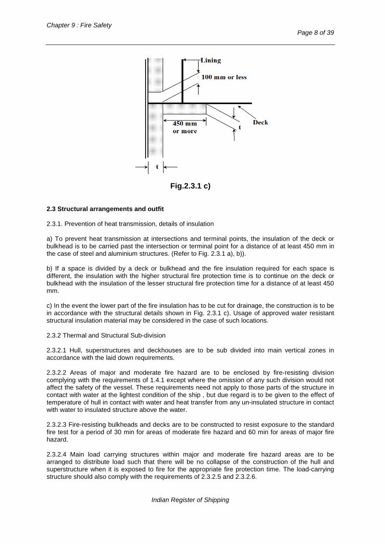
Chapter 9 : Fire Safety
Page 8 of 39
Fig.2.3.1 c)
2.3 Structural arrangements and outfit 2.3.1. Prevention of heat transmission, details of insulation a) To prevent heat transmission at intersections and terminal points, the insulation of the deck or bulkhead is to be carried past the intersection or terminal point for a distance of at least 450 mm in the case of steel and aluminium structures. (Refer to Fig. 2.3.1 a), b)). b) If a space is divided by a deck or bulkhead and the fire insulation required for each space is different, the insulation with the higher structural fire protection time is to continue on the deck or bulkhead with the insulation of the lesser structural fire protection time for a distance of at least 450 mm. c) In the event the lower part of the fire insulation has to be cut for drainage, the construction is to be in accordance with the structural details shown in Fig. 2.3.1 c). Usage of approved water resistant structural insulation material may be considered in the case of such locations. 2.3.2 Thermal and Structural Sub-division 2.3.2.1 Hull, superstructures and deckhouses are to be sub divided into main vertical zones in accordance with the laid down requirements. 2.3.2.2 Areas of major and moderate fire hazard are to be enclosed by fire-resisting division complying with the requirements of 1.4.1 except where the omission of any such division would not affect the safety of the vessel. These requirements need not apply to those parts of the structure in contact with water at the lightest condition of the ship , but due regard is to be given to the effect of temperature of hull in contact with water and heat transfer from any un-insulated structure in contact with water to insulated structure above the water. 2.3.2.3 Fire-resisting bulkheads and decks are to be constructed to resist exposure to the standard fire test for a period of 30 min for areas of moderate fire hazard and 60 min for areas of major fire hazard. 2.3.2.4 Main load carrying structures within major and moderate fire hazard areas are to be arranged to distribute load such that there will be no collapse of the construction of the hull and superstructure when it is exposed to fire for the appropriate fire protection time. The load-carrying structure should also comply with the requirements of 2.3.2.5 and 2.3.2.6.
Indian Register of Shipping

Rules and Regulations for the Construction and Classification of Indian Coast Guard Ships - 2015
Page 9 of 39
2.3.2.5 If the structures specified in 2.3.2.4 are made of aluminium alloy, their installation is to be such that the temperature of the core does not rise more than 200oC above the ambient temperature in accordance with the times in 2.1.1 and 2.1.2. 2.3.2.6 If the structures specified in 2.3.2.3 are made of combustible material, their insulation is to be such that their temperatures will not rise to a level where deterioration of the construction will occur during the exposure to the standard fire test in accordance with the FTP Code to such an extent that the load carrying capability, in accordance with the times in 2.1.1 and 2.1.2 will be impaired. 2.3.2.7 The construction of all doors and door frames in fire-resisting divisions, with the means of securing them when closed, is to provide resistance to fire as well as to the passage of smoke and flame equivalent to that of the bulkheads in which they are situated. Watertight sliding doors of steel need not be insulated. Also, where a fire-resisting division is penetrated by pipes, ducts, controls, electrical cables or for other purposes, arrangements are to be made to ensure that the fire-resisting integrity of the division is not impaired and necessary testing is to be carried out in accordance with FTP Code. 2.3.3 Restricted use of combustible materials 2.3.3.1 All separating divisions, ceilings or linings if not a fire resisting division, are to be of non-combustible materials. Draught stops are to be of non-combustible material. 2.3.3.2 Where insulation is installed in areas in which it could come into contact with any flammable fluids or their vapours, its surface is to be impermeable to such flammable fluids or vapours. The insulation may be covered by metal sheets (not perforated) or by vapour proof glass cloth effectively sealed at all joints. 2.3.3.3 Furniture and furnishings are to comply with the following standards:
a) all case furniture such as desks, wardrobes, dressing tables, bureaux and dressers is constructed entirely of approved non-combustible materials, except that a combustible veneer with a calorific value not exceeding 45 [MJ/m2] may be used on the exposed surface of such articles;
b) all other furniture such as chairs, sofas, tables, is constructed with frames of non-
combustible materials; c) all draperies, curtains and other suspended textile materials have qualities of resistance to
the propagation of flame, this being determined in accordance with the FTP Code; d) all upholstered furniture has qualities of resistance to the ignition and propagation of flame
this being determined in accordance with the FTP Code; e) all bedding components have qualities of resistance to the ignition and propagation of flame,
this being determined in accordance with the FTP Code; and f) all deck finish materials comply with the FTP Code.
2.3.3.4 The following surfaces, as a minimum standard, are to be constructed of materials having low flame-spread characteristics:
a) exposed surfaces in corridors and stairway enclosures and of bulkheads (including windows), wall and ceiling linings in all accommodation and service spaces, control stations and internal assembly and evacuation stations;
b) surfaces in concealed or inaccessible spaces in corridors and stairway enclosures,
accommodation and service spaces, control stations and internal assembly and evacuation stations.
Indian Register of Shipping

Chapter 9 : Fire Safety
Page 10 of 39
2.3.3.5 Any thermal and acoustic insulation is to be of non-combustible material. 2.3.3.6 Exposed surfaces in corridors and stairway enclosures and of bulkheads (including windows), wall and ceiling linings, in all spaces, control stations and internal assembly and evacuation stations are to be constructed of materials which, when exposed to fire, are not capable of producing excessive quantities of smoke or toxic products, this being determined in accordance with the FTP Code. 2.3.3.7 Void compartments, where low -density combustible materials are used to provide buoyancy, are to be protected from adjacent fire hazard areas by fire-resisting divisions, in accordance with Table 2.1. Also, the space and closures to it are to be gastight but it is to be ventilated to atmosphere. 2.3.3.8 In compartments where smoking is allowed, suitable non-combustible ash containers are to be provided. In compartments where smoking is not allowed, adequate notices are to be displayed. 2.3.3.9 The exhaust gas pipes are to be so arranged that the risk of fire is kept to a minimum. To this effect, the exhaust system is to be insulated and all the compartments and structures which are contiguous with the exhaust system, or those which may be affected by increased temperatures caused by waste gases in normal operation or in an emergency, are to be constructed of non-combustible material or be shielded and insulated with non-combustible material to protect from high temperatures. 2.3.3.10 The design and arrangement of the exhausts manifolds or pipes are to be such as to ensure the safe discharge of exhaust gases. Hot discharges from all safety / relief valves are to be directed to open spaces and guarded as necessary. 2.3.3.11 In accommodation and service spaces, control stations, corridors and stairways, air spaces enclosed behind ceilings, paneling or linings are to be suitably divided by close fitting draught stops not more than 14 [m] apart 2.3.4 Stairways and Lift trunks 2.3.4.1 Internal stairways connecting only two decks need only be enclosed at one deck by means of divisions and self-closing doors having the structural fire protection time as required by Table 2.1 for divisions separating those areas which each stairway serves. 2.3.4.2 Lift trunks are to be so fitted as to prevent the passage of smoke and flame from one deck to another and provided with means of closing so as to permit the control of draught and smoke. 2.3.5 Openings in fire-resisting divisions 2.3.5.1. All openings are to be provided with permanently attached means of closing which are to be at least as effective for resisting fires as the divisions in which they are fitted. 2.3.5.2 Each door is to be capable of being opened and closed from each side of the bulkhead by one person only. 2.3.5.3 Fire doors bounding areas of major fire hazard and stairway enclosures are to satisfy the following requirements: a) The doors are to be self-closing and be capable of closing with an angle of inclination of upto 3.5o opposing closure and are to have an approximately uniform rate of closure of no more than 40 [sec] and no less than 10 [sec] with the ship in the upright position. The approximate uniform rate of closure for sliding fire doors is to be of no more than 0.2 [m/s] and no less than 0.1 [m/s] with the ship in the upright position. b) Remote-controlled sliding or power-operated doors are to be equipped with an alarm that sounds at least 5s but no more than 10 [sec] before the door begins to move and continue sounding until
Indian Register of Shipping
Rules and Regulations for the Construction and Classification of Indian Coast Guard Ships - 2015
Page 11 of 39
the door is completely closed. Doors designed to re-open upon contacting an object in their paths are to re-open not more than 1 [metre] from point of contact. c) All doors are to be capable of remote and automatic release from a continuously manned central control station, either simultaneously or in groups and also individually from a position at both sides of the door. Indication is to be provided at the fire control panel in the continuously manned control station whether each of the remote controlled doors is closed. The release mechanism is to be so designed that the door will automatically close in the event of disruption of the control system or central power supply. Release switches are to have an on-off function to prevent automatic resetting of the system. Hold-back hooks not subject to control station release are not allowed. d) A door closed remotely from the continuously manned control station is to be capable of being re-opened at both sides of the door by local control. After such local opening, the door is to close automatically again. e) Local power accumulators for power-operated doors are to be provided in the immediate vicinity of the doors to enable the doors to be operated at least ten times (fully opened and closed) using the local controls. f) Disruption of the control system or main source of electric power at one door is not to impair the safe functioning of the other doors. g) Double-leaf doors equipped with a latch necessary to their fire integrity are to have a latch that is automatically activated by the operation of the doors when released by the system. h) The components of the local control system are to be accessible for maintenance and adjusting. i) Power operated doors are to be provided with a control system of an approved type which are be able to operate in case of fire, this being determined in accordance with the FTP Code. This system is to satisfy the following requirements: - The control system is to be able to operate at a temperature of at least 200°C for at least 60
[min], served by the power supply;
- The power supply for all other doors not subject to fire will not be impaired; and - At temperatures exceeding 200°C the control system is to be automatically isolated from the
power supply and is to be capable of keeping the door closed up to at least 945°C. 2.3.5.4 Doors in smoke-tight divisions are to be self-closing. Doors which are normally kept open are to be closed automatically or by remote control from a continuously manned control station.
Section 3
Fuel and other Flammable Fluid Tanks and Systems
3.1 Tanks containing fuel and other flammable fluids are to be separated from other compartments by vapour-proof enclosures or cofferdams which are suitably ventilated and drained. 3.2 Fuel oil tanks are not to be located in or contiguous to major fire hazard areas. However, flammable fluids of a flashpoint not less than 60oC may be located within such areas provided the tanks are made of steel or other equivalent material. 3.3 Integral or independent fuel tanks made of aluminium alloys, GRP or equivalent may be located within major fire hazard areas when they are insulated for 60 minutes fire integrity. The same
Indian Register of Shipping

Chapter 9 : Fire Safety
Page 12 of 39
insulation standard is required for bulkheads or decks separating oil fuel tanks from major fire hazard areas. 3.4 Every oil fuel pipe which, if damaged, would allow oil to escape from a storage, settling or daily service tank is to be fitted with a cock or valve directly on the tank capable of being closed from a position outside the space concerned in the event of fire occurring in the space in which such tanks are situated. 3.5 Pipes, valves and couplings conveying flammable fluids are to be of steel or such alternative material satisfactory to a standard, in respect of strength and fire integrity having regard to the service pressure and the spaces in which they are installed. Wherever practicable, the use of flexible pipes is to be avoided. 3.6 Pipes, valves and couplings conveying flammable fluids are to be arranged as far from hot surfaces or air intakes of engine installations, electrical appliances and other potential sources of ignition as is practicable and be located or shielded so that the likelihood of fluid leakage coming into contact with such sources of ignition is kept to a minimum. 3.7 Fuel with a flash point below 35oC is not to be used. In every vessel in which fuel with a flashpoint below 43o C is used or stored, the arrangements for the storage, distribution and utilization of the fuel are to be such that, having regard to the hazard of fire and explosion which the use of such fuel may entail, the safety of the vessel and of persons onboard is preserved. The arrangements are to comply, in addition to the requirements of 3.1 to 3.6, with the following provisions:
a) tanks for the storage of such fuel are to be located outside any machinery space and at a distance of not less than 760 [mm] inboard from the shell side and bottom plating, and from decks and bulkheads;
b) arrangements are to be made to prevent overpressure in any fuel tank or in any part of the
oil fuel system, including the filling pipes. Any relief valves and air or overflow pipes are to discharge to a position which is safe;
c) the spaces in which fuel tanks are located are to be mechanically ventilated using exhaust
fans providing not less than six air changes per hour. The fans are to be such as to avoid the possibility of ignition of flammable gas air mixtures. Suitable wire mesh guards are to be fitted to inlet and outlet ventilation openings. The outlets for such exhausts are to be discharged to a position which is safe. ‘No smoking’ signs are to be posted at the entrances to such spaces;
d) earthed electrical distribution systems are not to be used, with the exception of earthed
intrinsically safe circuits; e) suitable certified safe type electrical equipment is to be used in all spaces where fuel
leakage could occur, including ventilation system. Only electrical equipment and fittings essential for operational purposes are to be fitted in such spaces;
Note : Refer to the recommendations published by the International Electro-technical Commission, and in particular, publication 92 – Electrical installations in ships.
f) a fixed vapour detection system is to be installed in each space through which fuel lines pass, with alarms provided at the continuously manned control station;
g) every fuel tank where necessary, is to be provided with ‘‘save-all’s’’ or gutters which would
catch any fuel which may leak from such tank; h) safe and efficient means of ascertaining the amount of fuel contained in any tank are to be
provided. Sounding pipes are not terminate in any space where the risk of ignition of spillage from the sounding pipe might arise. In particular, they are not to terminate in
Indian Register of Shipping

Rules and Regulations for the Construction and Classification of Indian Coast Guard Ships - 2015
Page 13 of 39
accommodation or operations spaces. The use of gauge glasses is not allowed. Other means of ascertaining the amount of fuel contained in any tank may be allowed if such means do not require penetration below the top of the tank and provided their failure or overfilling of the tank will not permit the release of fuel;
i) the provision of fire detection and extinguishing systems in spaces where non-integral fuel
tanks are located are to be in accordance with clauses 5.1 to 5.3 of Section 5.
Section 4
Ventilation
4.1 The main inlets and outlets of all ventilation systems are to be capable of being closed from outside the spaces being ventilated. In addition, such openings to areas of major fire hazard are to be capable of being closed from a continuously manned control station. The controls are to be easily accessible as well as prominently and permanently marked and are to indicate whether the shut-off is open or closed. 4.2 All ventilation fans are to be capable of being stopped from outside the spaces which they serve, and from outside the spaces in which they are installed. Ventilation fans serving major fire hazard areas are to be capable of being operated from a continuously manned control station. The means provided for stopping the power ventilation to the machinery space are to be separated from the means provided for stopping ventilation of other spaces. 4.3 Areas of major fire hazard and spaces serving as assembly stations are to have independent ventilation systems and ventilation ducts. Ventilation ducts for areas of major fire hazard are not to pass through other spaces, unless they are contained within a trunk or in an extended machinery space or casing insulated in accordance with Tables 2.1. Ventilation ducts of other spaces are not to pass through areas of major fire hazard. Ventilation outlets from areas of major fire hazard are not to terminate within a distance of 1 [m] from any control station, evacuation station or external escape route. In addition, exhaust ducts from galley ranges are to be fitted with the following:
a) a grease trap readily removable for cleaning, unless an alternative approved grease removal system is fitted;
b) a fire damper located in the lower end of the duct which is automatically and remotely
operated and in addition a remotely operated fire damper located in the upper end of the duct;
c) a fixed means for extinguishing a fire within the duct;
d) remote control arrangements for shutting off the exhaust fans and supply fans, for operating
the fire dampers mentioned in b) and for operating the fire-extinguishing system, which is to be placed in a position close to the entrance to the galley. Where a multi-branch system is installed, means are to be provided to close all branches exhausting through the same main duct before an extinguishing medium is released into the system; and
e) suitably located hatches for inspection and cleaning.
4.4 Where, a ventilation duct passes through a fire-resisting division, a fail safe automatic closing fire damper is to be fitted adjacent to the division. The duct between the division and the damper is to of steel or other equivalent material and insulated to the same standard as required for the fire-resisting division. The fire damper may be omitted where ducts pass through spaces surrounded by fire-resisting divisions without serving those spaces provided that the duct has the same structural fire protection time as the divisions it penetrates. Where a ventilation duct passes through a smoke-
Indian Register of Shipping

Chapter 9 : Fire Safety
Page 14 of 39
tight division, a smoke damper is to be fitted at the penetration unless the duct which passes through the space does not serve that space. The fire and smoke dampers are to be easily accessible. Where they are placed behind ceilings or linings, they are to be provided with an inspection door on which a plate is fitted providing the identification number of the damper. Such plates with identification numbers are also to be placed on any required remote controls. 4.5 Where ventilation systems penetrate decks, the arrangements are to be such that the effectiveness of the deck in resisting fire is not thereby impaired and precautions are to be taken to reduce the likelihood of smoke and hot gases passing from one between deck space to another through the system. 4.6 All dampers fitted on fire-resisting or smoke-tight divisions are also to be capable of being manually closed from each side of the division in which they are fitted, except for those dampers fitted on ducts serving spaces not normally manned such as stores and toilets that may be manually operated only from outside the served spaces. All dampers are also to be capable of being remotely closed from the continuously manned control station. Manual closing may be achieved by mechanical means of release or by remote operation of the fire or smoke damper by a fail-safe electrical switch or pneumatic release (i.e. spring-loaded, etc.) 4.7 Ducts are to be made of non-combustible material. 4.8 Where additional class notation ‘Fire zones’ is to be assigned, the requirements of independent ventilation systems and smoke extraction systems of Part 6, Chapter 8 of the Rules and Regulations for the Construction and Classification of Steel Ships are to be complied with.
Section 5
Fire Detection and Extinguishing Systems
5.1 Fire detection systems Areas of major and moderate fire hazard and other enclosed spaces not regularly occupied, are to be provided with an approved automatic smoke detection system and manually operated call points complying with the requirements of 5.1.1 and 5.1.3 to indicate at the control station the location of outbreak of a fire in all normal operating conditions of the installations. Detectors operated by heat as well as smoke may be installed in galleys. Main propulsion machinery room(s) are to have detectors sensing heat and smoke. Manually operated call points are to be installed throughout the accommodation corridor and stairway enclosures, service spaces and where necessary at control stations. One manually operated call point is to be located at each exit from these spaces and from areas of major fire hazard. Control stations not normally occupied (e.g. emergency generator rooms) need not be provided with manually operated call points. 5.1.1 General Requirements of Fire Detection Systems
a) Any required fixed fire detection and fire alarm system with manually operated call points is to be capable of immediate operation at all times;
b) Power supplies and electric circuits necessary for the operation of the system are to be
monitored for loss of power or fault conditions as appropriate. Occurrence of fault condition is to initiate a visual and audible fault signal at the control panel which is to be distinct from a fire signal;
c) Not less than two sources of power supply for the electrical equipment are to be used in the
operation of the fire detection and fire alarm systems, one of which is to be emergency Indian Register of Shipping

Rules and Regulations for the Construction and Classification of Indian Coast Guard Ships - 2015
Page 15 of 39
source. The supply is to be provided by separate feeders reserved solely for this purpose. Such feeders are to run to an automatic change over switch situated in or adjacent to the control panel for the fire detection system;
d) Detectors and manually operated call points are to be grouped into sections. The activation
of any detector or manually operated call point is to initiate a visual and audible fire signal at the control panel and indicating units. If the signals have not received attention within two minutes an audible alarm is to be automatically sounded throughout the accommodation and service spaces, control stations and machinery spaces. There shall be no time delay for the audible alarms in crew accommodation areas when all the control stations are unattended. The alarm sounder system need not be an integral part of the detection system;
e) The control panel is to be located in the navigation bridge or in the main fire control station
or in the machinery control station; f) Indicating units are to, as a minimum, denote the section in which a detector or manually
operated call point has operated. At least one unit is to be so located that it is easily accessible to responsible members of the crew at all times.. One indicating unit is to be located in the navigation bridge if the control panel is located in the space other than the navigation bridge;
g) Clear information is to be displayed on or adjacent to each indicating unit about the spaces
covered and the location of the sections; h) A section of fire detectors which covers a control station, a service space, accommodation
space, corridor or stairway enclosure are not to include a machinery space of major fire hazard. For fire detection systems with remotely and individually identifiable fire detectors, the requirement set out in this paragraph is considered met when a loop covering accommodation spaces, service spaces and control stations, does not include spaces of a major fire hazard;
i) Detectors are to be operated by heat, smoke or other products of combustion, flame, or any
combination of these factors. Detectors operated by other factors indicative of incipient fires may be considered provided that they are no less sensitive than such detectors. Flame detectors are only to be used in addition to smoke or heat detectors;
j) Suitable instructions and component spares for testing and maintenance are to be provided; k) The function of the detection system is to be periodically tested by means of equipment
producing hot air at the appropriate temperature, or smoke or aerosol particles having the appropriate range of density or particle size, or other phenomena associated with incipient fires to which the detector is designed to respond. All detectors are to be of a type such that they can be tested for correct operation and restored to normal surveillance without the renewal of any component;
l) The fire detection system is not be used for any other purpose, except that following
functions may be permitted at the control panel:
- To activate a paging system; - To activate the fan stops; - To activate the closure of fire doors; - To activate the closure of fire and smoke dampers; - To activate the sprinkler system.
m) Fire detection systems with a zone address identification capability are to be so arranged
that;
Indian Register of Shipping

Chapter 9 : Fire Safety
Page 16 of 39
- a loop cannot be damaged at more than one point by a fire. For this purpose loop is not
to pass through a space twice. Where this is not practical the part of the loop which by necessity passes through the space for a second time is to be installed at the maximum possible distance from the other parts of the loop;
- means are provided to ensure that any fault (e.g. power break; short circuit; earth)
occurring in the loop will not render the whole loop ineffective; - all arrangements are made to enable the initial configuration of the system to be
restored in the event of failure (electrical, electronic, informatic); and - the first initiated fire alarm is not to prevent any other detector to initiate further fire
alarms.
5.1.2 Installation Requirements of Fire Detection Systems
a) In addition to 5.1, manually operated call points are to be readily accessible in the corridors of each deck such that no part of the corridor is more than 20 [m] from a manually operated call point;
b) Where a fixed fire detection and fire alarm system is required for the protection of spaces
other than stairways, corridors and escape routes, at least one detector complying with 5.1.1 i) is to be installed in each such space;
c) Detectors are to be located for optimum performance. Positions near beams and ventilation
ducts or other positions where patterns of air flow could adversely affect performance and positions where impact or physical damage is likely should be avoided. In general, detectors, which are located on the deckhead, are to be a minimum distance of 0.5 [m] away from bulkheads. Distances smaller than 0.5 [m] from bulkheads may be accepted in corridors, lockers and stairways.
d) The maximum spacing of detectors are to be in accordance with the table below:
Type of detector Max. floor area
per detector [m2] Max. distance apart between
centres [m]
Max. distance away from
bulkheads [m] Heat 37 9 4.5
Smoke 74 11 5.5
Other spacings may be required or permitted based upon test data, which demonstrate the characteristics of the detectors.
e) Electrical wiring which forms part of the system is to be so arranged as to avoid spaces of major fire hazard, except, where it is necessary, to provide for fire detection or fire alarm in such spaces or to connect to the appropriate power supply.
5.1.3 Design Requirements of Fire Detection Systems
a) The system and equipment are to be suitably designed to withstand supply voltage variation and transients, ambient temperature changes, vibration, humidity, shock, impact and corrosion normally encountered in ships;
b) Smoke detectors are to be certified to operate before the smoke density exceeds 12.5%
obscuration per metre, but not until the smoke density exceeds 2% obscuration per metre. c) Heat detectors are to be certified to operate before the temperature exceeds 78oC but not
until the temperature exceeds 54oC, when the temperature is raised to those limits at a rate less than 1oC per minute. At higher rates of temperature rise, the heat detector is to operate
Indian Register of Shipping

Rules and Regulations for the Construction and Classification of Indian Coast Guard Ships - 2015
Page 17 of 39
within temperature limits having regard to the avoidance of detector insensitivity or over-sensitivity;
d) The permissible temperature of operation of heat detectors may be increased to 30oC above
the maximum deckhead temperature in drying rooms and similar space of a normal high ambient temperature;
e) Flame detectors referred in 5.1.1 i) are to have sensitivity sufficient to determine flame
against an illuminated space background and a false signal identification system. 5.1.4 Additional Requirements for Fixed Fire Detection and Fire Alarm System for periodically unattended machinery spaces:
a) The fire detection system is to be so designed and the detectors so positioned as to detect rapidly the onset of fire in any part of those spaces and under any normal conditions of operation of the machinery and variations of ventilation as required by the possible range of ambient temperatures. Except in spaces of restricted height and where their use is especially appropriate, detection system using only thermal detectors is not permitted. The detection system is to initiate audible and visual alarms distinct in both respects from the alarms of any other system not indicating fire, in sufficient places to ensure that the alarms are heard and observed on the navigating bridge and by a responsible engineer officer. When the navigation bridge is unmanned the alarm is to sound in a place where a responsible member of the crew is on duty; The alarm is also to sound in the a place where a responsible member of the crew is on duty even in harbour condition when the navigation bridge may be unmanned.
b) After installation, the system is to be tested under varying conditions of engine operation
and ventilation.
5.2 Fixed fire extinguishing systems 5.2.1 Spaces of major fire hazard are to be protected by an approved fixed extinguishing system operable from the control position, which is adequate for the fire hazard that may exist. The system is to comply with 5.2.2 and 5.2.3 or with alternative arrangements approved by IRS and be capable of local manual control and remote control from the continuously manned control stations. The system is to be remotely controlled in such a way that it is fully serviceable from the navigation bridge without any intervention of personnel outside that space in normal conditions. In areas of major fire hazard where Internal Combustion Engines and Fuel Oil Handling Equipments are fitted, approved Fixed Local Application Fire Fighting Systems are to be provided. 5.2.2 General Requirements of Fixed Fire Extinguishing Systems
a) In all ships where gas is used as the extinguishing medium, the quantity of gas is to be sufficient to provide two independent discharges. The second discharge into the space is to be only activated (released) manually from a position outside the space being protected. b) The use of a fire extinguishing medium which, either by itself or under expected conditions of use will adversely affect the earth’s ozone layer and/or gives off toxic gases in such quantities as to endanger persons, is not allowed. c) The necessary pipes for conveying fire-extinguishing medium into protected spaces are to be provided with control valves so marked as to indicate clearly the spaces to which the pipes are led. Non-return valves are to be installed in discharge lines between cylinders and manifolds. Suitable provision is to be made to prevent inadvertent admission of the medium to any space. d) Pipelines may pass through accommodation spaces provided they are of substantial thickness and that their tightness is verified with a pressure test, after their installation, at a pressure head not less than 5 [N/mm2]. In addition, pipelines passing through
Indian Register of Shipping

Chapter 9 : Fire Safety
Page 18 of 39
accommodation areas are only to be joined by welding and are not to be fitted with drains or other openings within such spaces. Pipelines are not to pass through refrigerated spaces. e) The piping for the distribution of fire extinguishing medium are to be arranged and discharge nozzles so positioned that a uniform distribution of medium is obtained. f) Means are to be provided to close all openings which may admit air to, or allow gas to escape from, a protected space from a position outside the protected space. (For closing of openings for ventilation fans and stopping of ventilation fans, refer Section 4). g) Means are to be provided for automatically giving audible warning of the release of fire-extinguishing medium into any space in which personnel normally work or to which they have access. The alarm is to operate for a suitable period before the medium is released, but not less than 20 [sec]. Visible alarms are to be arranged in addition to the audible alarm. h) The volume of starting air receivers, converted to free air volume are to be added to the gross volume of the machinery space when calculating the necessary quantity of extinguishing medium. Alternatively, a discharge pipe connected to a safety valve may be fitted provided it leads directly to the open air. i) The means of control of any fixed gas fire extinguishing system is to be readily accessible and simple to operate and be grouped together in as few locations as possible at positions not likely to be cut off by a fire in a protected space. At each location there are to be clear instructions relating to the operation of the system having regard to the safety of personnel. j) Automatic release of fire extinguishing medium is not allowed. k) Where the quantity of extinguishing medium is required to protect more than one space, the quantity of medium available need not be more than the largest quantity required for any one space so protected. Two spaces can be considered as separated spaces where divisions comply with Table 2.1 or the divisions are of steel construction. See also a) above. l) Pressure containers required for the storage of fire extinguishing medium are to be located outside protected spaces in accordance with o) below. Pressure containers may be located inside the space to be protected if in the event of accidental release persons will not be endangered. m) Means are to be provided for the crew to safely check the quantity of medium in the containers. Means for checking the quantity of medium in containers are to be so arranged that it is not necessary to move the containers completely from their fixing position. This may be achieved for instance by providing hanging bars above each bottle row for a weighting device or by using suitable surface indicators. n) Containers for the storage of fire extinguishing medium and associated pressure components are to be designed to accepted pressure codes of practice to the satisfaction of IRS having regard to their locations and maximum ambient temperatures expected in service. o) When the fire extinguishing medium is stored outside a protected space, it is to be stored in a room which is situated in a safe and readily accessible position and effectively ventilated. Any entrance to such a storage room is to be preferably from the open deck and in any case is to be independent of the protected space. Access doors are to open outwards and bulkheads and decks including doors and other means of closing any opening therein, which form the boundaries between such rooms and adjoining enclosed spaces, are to be gas tight. For the purpose of application of Table 2.1, such storage rooms are to be treated as control stations. Spaces for storage of the cylinders or tanks for extinguishing gas are not to be used for other purposes. Spaces situated below the deck are to be directly accessible by a stairway or ladder from the open deck. The space is to be located no more than one deck below the open deck. Storage rooms are to be provided with a mechanical ventilation
Indian Register of Shipping
Rules and Regulations for the Construction and Classification of Indian Coast Guard Ships - 2015
Page 19 of 39
system, capable of maintaining ambient temperature specified by the suppliers and effecting at least 15 air changes per hour; if such rooms have a direct door access to open deck, natural ventilation may suffice. p) If the release of a fire-extinguishing medium produces significant over or under pressurization in the protected space, means are to be provided to limit the induced pressures to acceptable limits to avoid structural damage. q) At least one set of essential spares for the system are to be stored on board.
5.2.3 Carbon dioxide Systems
a) For machinery spaces the quantity of carbon dioxide is to be sufficient to give a minimum volume of free gas equal to the larger of the following volumes, either:
- 40% of the gross volume of the largest machinery space so protected, the volume
to exclude that part of the casing above the level at which the horizontal area of the casing is 40% or less of the horizontal area of the space concerned taken midway between the tank top and the lowest part of the casing; or
- 35% of the gross volume of the largest machinery space protected, including the
casing;
b) For the purpose of this paragraph the volume of free carbon dioxide is to be calculated at 0.56 [m3/kg].
c) For machinery spaces the fixed piping system is to be such that 85% of the gas can be
discharged into the space within 2 [min]. d) Two separate controls are to be provided for releasing carbon dioxide into a protected
space and to ensure the activation of the alarm. One control is to be used to discharge the gas from its storage containers. A second control is to be used for opening the valve of the piping which conveys the gas into the protected spaces.
e) The two controls are to be located inside a release box clearly identified for the
particular space. If the box containing the controls is to be locked, a key to the box is to be in a break-glass type enclosure conspicuously located adjacent to the box.
5.3 Portable fire extinguishers 5.3.1 Control stations, accommodation spaces, corridors and service spaces are to be provided with portable fire extinguishers of approved types and design. At least five portable extinguishers are to be provided in each vertical fire zone so positioned as to be readily available for immediate use. In addition, at least one extinguisher suitable for machinery space fires are to be positioned outside each machinery space entrance. For details of extinguishers reference is made to IMO Resolution A.602(15) titled “Revised Guidelines for Marine Portable Fire Extinguishers”. 5.3.2 Mass and Capacity of Portable Fire Extinguishers
a) The mass of portable fire extinguishers is not to exceed 23 [kg].
b) Each powder or carbon dioxide extinguisher is to have a capacity of at least 5 [kg] and each foam extinguisher a capacity of at least 9 [litre].
Indian Register of Shipping
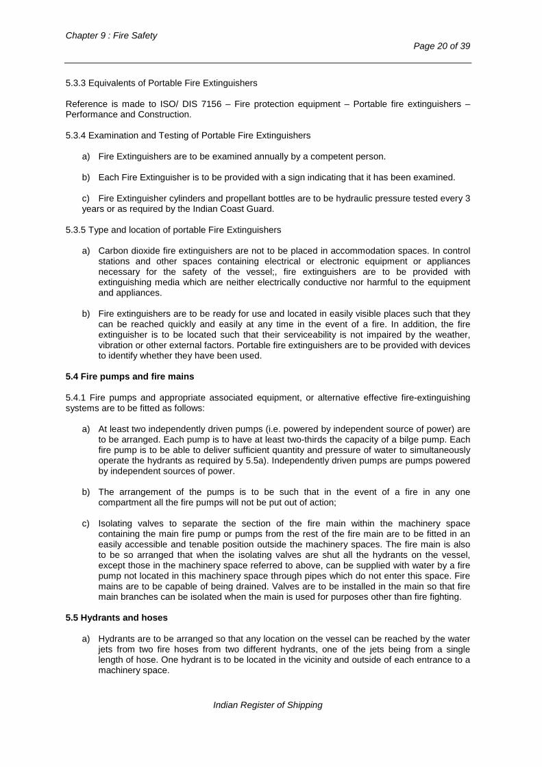
Chapter 9 : Fire Safety
Page 20 of 39
5.3.3 Equivalents of Portable Fire Extinguishers Reference is made to ISO/ DIS 7156 – Fire protection equipment – Portable fire extinguishers – Performance and Construction. 5.3.4 Examination and Testing of Portable Fire Extinguishers
a) Fire Extinguishers are to be examined annually by a competent person.
b) Each Fire Extinguisher is to be provided with a sign indicating that it has been examined.
c) Fire Extinguisher cylinders and propellant bottles are to be hydraulic pressure tested every 3 years or as required by the Indian Coast Guard.
5.3.5 Type and location of portable Fire Extinguishers
a) Carbon dioxide fire extinguishers are not to be placed in accommodation spaces. In control stations and other spaces containing electrical or electronic equipment or appliances necessary for the safety of the vessel;, fire extinguishers are to be provided with extinguishing media which are neither electrically conductive nor harmful to the equipment and appliances.
b) Fire extinguishers are to be ready for use and located in easily visible places such that they
can be reached quickly and easily at any time in the event of a fire. In addition, the fire extinguisher is to be located such that their serviceability is not impaired by the weather, vibration or other external factors. Portable fire extinguishers are to be provided with devices to identify whether they have been used.
5.4 Fire pumps and fire mains 5.4.1 Fire pumps and appropriate associated equipment, or alternative effective fire-extinguishing systems are to be fitted as follows:
a) At least two independently driven pumps (i.e. powered by independent source of power) are to be arranged. Each pump is to have at least two-thirds the capacity of a bilge pump. Each fire pump is to be able to deliver sufficient quantity and pressure of water to simultaneously operate the hydrants as required by 5.5a). Independently driven pumps are pumps powered by independent sources of power.
b) The arrangement of the pumps is to be such that in the event of a fire in any one
compartment all the fire pumps will not be put out of action;
c) Isolating valves to separate the section of the fire main within the machinery space containing the main fire pump or pumps from the rest of the fire main are to be fitted in an easily accessible and tenable position outside the machinery spaces. The fire main is also to be so arranged that when the isolating valves are shut all the hydrants on the vessel, except those in the machinery space referred to above, can be supplied with water by a fire pump not located in this machinery space through pipes which do not enter this space. Fire mains are to be capable of being drained. Valves are to be installed in the main so that fire main branches can be isolated when the main is used for purposes other than fire fighting.
5.5 Hydrants and hoses
a) Hydrants are to be arranged so that any location on the vessel can be reached by the water jets from two fire hoses from two different hydrants, one of the jets being from a single length of hose. One hydrant is to be located in the vicinity and outside of each entrance to a machinery space.
Indian Register of Shipping

Rules and Regulations for the Construction and Classification of Indian Coast Guard Ships - 2015
Page 21 of 39
b) Each fire hose is to be of non-perishable material. Fire hoses, together with any necessary fittings and tools, are to be kept ready for use in conspicuous positions near the hydrants. All fire hoses in interior locations are to be connected to the hydrants at all times. One fire hose is to be provided for each hydrant as required by d) above. Fire hoses are to have a length of:
- At least 10 m, - Not more than 15 m in machinery spaces, - Not more than 20 m for other spaces and open decks.
c) The sizes of fire hoses and hydrants are to be 50 or 65 [mm] nominal bore. d) Each hose is to be provided with a nozzle of an approved dual purpose type (i.e. spray / jet
type) incorporating a shutoff. The standard nozzle sizes to be used are 12 [mm], 16 [mm] and 19 [mm]. The nozzle sizes are to be chosen such as to obtain the maximum discharge possible from two jets (see 5.5.1a) and 5.6a) at a pressure of not less than 0.50 [N/mm2] at the hydrant.
5.6 Shore connections 5.6.1 Ships of 500 GT and upwards are to be provided with at least one international shore connection complying with the Fire Safety Systems Code. 5.6.2 Facilities are to be available enabling such a connection to be used on either side of the ship. 5.7 Weapons, magazines and ammunition spaces 5.7.1 The arrangements and provisions for the fire detection, fire protection and extinguishing systems in these spaces and where relevant the adjacent spaces, are to be in accordance with the requirements specified by the Indian Coast Guard Authority. 5.8 Protection of deep-fat cooking equipment Where deep-fat cooking equipment is installed, all such installations are to be fitted with: a) A fixed extinguishing system tested to ISO 15371:2000 “Fire extinguishing systems for
protection of galley deep fat cooking equipment”. b) A primary and back up thermostat with an alarm to alert the operator in the event of failure of
either thermostat; c) Arrangements for automatically shutting off the electrical power to the deep-fat cooking
equipment upon activation of the extinguishing system; d) An alarm indicating operation of the extinguishing system in the galley where the equipment is
installed; and e) Controls for manual operation of the extinguishing system which are clearly labeled for ready
use by the crew.
Indian Register of Shipping
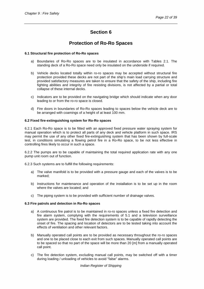
Chapter 9 : Fire Safety
Page 22 of 39
Section 6
Protection of Ro-Ro Spaces
6.1 Structural fire protection of Ro-Ro spaces
a) Boundaries of Ro-Ro spaces are to be insulated in accordance with Tables 2.1. The standing deck of a Ro-Ro space need only be insulated on the underside if required.
b) Vehicle decks located totally within ro-ro spaces may be accepted without structural fire
protection provided these decks are not part of the ship’s main load carrying structure and provided satisfactory measures are taken to ensure that the safety of the ship, including fire fighting abilities and integrity of fire resisting divisions, is not affected by a partial or total collapse of these internal decks.
c) Indicators are to be provided on the navigating bridge which should indicate when any door
leading to or from the ro-ro space is closed. d) Fire doors in boundaries of Ro-Ro spaces leading to spaces below the vehicle deck are to
be arranged with coamings of a height of at least 100 mm.
6.2 Fixed fire-extinguishing system for Ro-Ro spaces 6.2.1 Each Ro-Ro space is to be fitted with an approved fixed pressure water spraying system for manual operation which is to protect all parts of any deck and vehicle platform in such space. IRS may permit the use of any other fixed fire-extinguishing system that has been shown by full-scale test, in conditions simulating a flowing petrol fire in a Ro-Ro space, to be not less effective in controlling fires likely to occur in such a space. 6.2.2 The pumps are to be capable of maintaining the total required application rate with any one pump unit room out of function. 6.2.3 Such systems are to fulfill the following requirements:
a) The valve manifold is to be provided with a pressure gauge and each of the valves is to be marked;
b) Instructions for maintenance and operation of the installation is to be set up in the room
where the valves are located; and c) The piping system is to be provided with sufficient number of drainage valves.
6.3 Fire patrols and detection in Ro-Ro spaces
a) A continuous fire patrol is to be maintained in ro-ro spaces unless a fixed fire detection and fire alarm system, complying with the requirements of 5.1 and a television surveillance system are provided. The fixed fire detection system is to be capable of rapidly detecting the onset of fire. The spacing and location of detectors are to be tested taking into account the effects of ventilation and other relevant factors.
b) Manually operated call points are to be provided as necessary throughout the ro-ro spaces
and one to be placed close to each exit from such spaces. Manually operated call points are to be spaced so that no part of the space will be more than 20 [m] from a manually operated call point.
c) The fire detection system, excluding manual call points, may be switched off with a timer
during loading / unloading of vehicles to avoid "false” alarms.
Indian Register of Shipping

Rules and Regulations for the Construction and Classification of Indian Coast Guard Ships - 2015
Page 23 of 39
6.4 Fire extinguishing equipment in Ro-Ro spaces In each ro-ro spaces the following are to be provided:
a) At least three water fog applicators (Note : A water fog applicator may consist of a metal L-shaped pipe, the long limb being approximately 2 [m] in length and capable of being fitted to a fire hose and the short limb being approximately 250 [mm] in length and fitted with a fixed water fog nozzle or capable of being fitted with a water spray nozzle);
b) One portable foam applicator unit consisting of an air foam nozzle of an inductor type
capable of being connected to the fire main by a fire hose, together with a portable tank containing 20 [lit] of foam making liquid and one spare tank. The nozzle is to be capable of producing effective foam suitable for extinguishing an oil fire of at least 1.5 [m3/min]. At least two portable foam applicator units are to be available in the Ship for use in such space; and
c) Portable fire extinguishers so located that no point in the space is more than approximately
15 [m] walking distance from an extinguisher, provided that at least one portable extinguisher is located at each access to such space. Fire extinguishers are to be suitable for A and B class fires as given in IMO Resolution A.602(15). The extinguishers are to have a capacity of 12 [kg] dry powder or equivalent. The mass and capacity of fire extinguishers are to meet the requirements of 5.3.2.
6.5 Ventilation system of Ro-Ro spaces 6.5.1 An effective power ventilation system is to be provided for the ro-ro spaces sufficient to give at least 10 air changes per hour while navigating and 20 air changes per hour during vehicle loading and unloading operations. The system for such spaces is to be entirely separated from other ventilation systems and is to be operating at all times when vehicles are in such spaces. Ventilation ducts serving ro-ro spaces capable of being effectively sealed are to be separated for each such space. The system is to be capable of being controlled from a position outside such spaces. 6.5.2 The ventilation is to be such as to prevent air stratification and the formation of air pockets. 6.5.3 Means are to be provided to indicate on the navigation bridge any loss or reduction of the required ventilating capacity. 6.5.4 Arrangements are to be provided to permit a rapid shutdown and effective closure of the ventilation system in case of fire, taking into account the weather and sea conditions. 6.5.5 Ventilation ducts, including dampers are to be made of steel or other equivalent material. Ducts lying inside the served space may be made of non-combustible material. 6.6 Scuppers, bilge pumping and drainage of Ro-Ro spaces 6.6.1 In view of the serious loss of stability which could arise due to large quantities of water accumulating on the deck or decks consequent to the operation of the fixed pressure water spraying system, scuppers are to be fitted so as to ensure that such water is rapidly discharged directly overboard. Alternatively, pumping and drainage facilities are to be provided in addition to the requirements of Chapter 3, Part 4. 6.6.2 Unless justificatory calculations are submitted, scuppers of at least 150 [mm] in diameter are to be fitted every 9 [m] on both sides. 6.6.3 When it is required to maintain watertight or weathertight integrity, as appropriate, the scuppers shall be arranged so that they can be operated from outside the space protected.
Indian Register of Shipping

Chapter 9 : Fire Safety
Page 24 of 39
6.7 Precautions against ignition of flammable vapours 6.7.1 On any deck or platform, if fitted, on which vehicles are carried and on which explosive vapours might be expected to accumulate, except platforms with openings of sufficient size permitting penetration of petrol gases downwards, equipment which may constitute a source of ignition of flammable vapours and, in particular, electrical equipment and wiring, are to be installed at least 450 [mm] above the deck or platform. Electrical equipment installed at more than 450 [mm] above the deck or platform are to be of a type so enclosed and protected as to prevent the escape of sparks. However, if the installation of electrical equipment and wiring at less than 450 [mm] above the deck or platform is necessary for the safe operation of the ship, such electrical equipment and wiring may be installed provided that it is of a type approved for use in an explosive mixture of petrol and air. 6.7.2 For equipment above a height of 450 [mm] above the deck:
− The degree of protection for electrical equipment required by this section is to be by an
enclosure having an ingress protection of at least IP 55 as defined in IEC Publication 529 – Classification of Degree of Protection provided by Enclosures or by apparatus for use in zone 2 areas as defined in IEC Publication 79 – Electrical apparatus for explosive gas atmospheres (Temperature Class T3).
6.7.3 For equipment at or below a height of 450 [mm] above deck:
− The electrical equipment referred to in this section is to be certified “safe type” and wiring, if
fitted, is to be suitable for use in zone 1 areas as defined in IEC Publication 79 – Electrical Apparatus for Explosive Gas Atmospheres – (Gas Group II A and Temperature Class T3).
6.7.4 Electrical equipment and wiring, if installed in an exhaust ventilation duct, are to be of a type approved for use in explosive petrol and air mixtures and the outlet from any exhaust duct are to be sited in a safe position, having regard to other possible sources of ignition. The electrical equipment referred to in this para are to be of a type similar to those required for less than 450 [mm] above deck given in 6.7.3. 6.7.5 Exhaust fans are to be of a non-sparking type. 6.7.6 If pumping and drainage arrangements are provided, it is to be ensured that: a) Water contaminated with petrol or other flammable substances is not drained to machinery
spaces or other spaces where sources of ignition may be present; and b) Electrical equipment fitted in tanks or other components of the drainage system are to be of a
type suitable for use in explosive petrol/air mixtures. 6.8 Open Ro-Ro spaces 6.8.1 Open ro-ro spaces are to comply with the requirements set out in 6.1a), 6.2, 6.3, 6.4 and 6.6. 6.8.2 For those parts of a ro-ro space which is completely open from above, the requirements set out in 6.2, 6.3a) and 6.6 need not be complied with. However, a continuous fire patrol or a television surveillance system is to be maintained.
Indian Register of Shipping

Rules and Regulations for the Construction and Classification of Indian Coast Guard Ships - 2015
Page 25 of 39
Section 7
Fire Protection of Helicopter Facilities
7.1 In general, the helicopter landing deck and the boundaries of helicopter handling and fuelling areas shall be constructed of steel or equivalent material and insulated to 60 [min] fire protection time standard. 7.2 Heli decks are to be provided with both main and emergency means of escape/evacuation and access for fire fighting and rescue. These shall be located as far from each other as possible. 7.3 In close proximity to the heli deck and near the access, the following fire fighting appliances shall be provided:
- at least two dry powder extinguishers having total capacity not less than 45 kg - carbon di oxide extinguishers of total capacity 18 kg - a suitable foam application system consisting of monitors or foam-making branch pipes
capable of delivering foam to all parts of the helicopter facilities in all weather conditions in which helicopters can operate. The system shall be capable of delivering a discharge rate for 5 [min] of 250 [litres/min] for helicopters upto 15 [m] length, 500 [litres/min] for helicopters of length 15 upto 24 [m], 800 [litres / min] for helicopters of length 24 upto 35 [m]. The foam compound should be of approved type and compatible for usage with sea water.
- at least two dual purpose nozzles and hoses to reach any part of the helicopter service areas
- two additional sets of fireman’s out fits - at least the following equipments, protected from the weather:
- adjustable wrench - fire resistant blanket - bolt cutter, 60 [mm] - grab or slaving hook - heavy duty hack saw with 6 spare blades - ladder - life line of 5 [mm] diameter and 15 [m] length - side cutting pliers - assorted screw drivers - harness knife with sheath
7.4 Drainage facilities at heli deck are to be of steel and shall lead directly over board independent of any other system. 7.5 Helicopter fuel tanks shall be located at a designated area, as far removed from other areas of major fire risk as possible and away from main escape routes. Arrangements are to be provided to drain any spillage to safe locations. Tanks and associated fittings are to be protected from physical damages and from fire in adjacent spaces by suitably insulated boundaries or coffer dams. 7.6 All piping for helicopter fuel handling are to be of steel or equivalent material. Only approved flexible pipes are to be used for fuelling the helicopters. Suitable devices are to be provided to prevent over pressurisation of the piping. 7.7 All electrical equipments in the vicinity of helicopter fuelling arrangements are to be intrinsically safe and explosion proof as per applicable international standards. All electrical cabling and wiring shall be as per 6.7 of the requirements for Ro-Ro spaces as applicable.
Indian Register of Shipping

Chapter 9 : Fire Safety
Page 26 of 39
Section 8
Escape
8.1 Notification to crew 8.1.1 A General Alarm System or Public Address System, operable on normal and emergency modes, is to be provided on board to notify the crew at all locations of the ship, of a fire on board. 8.1.2 General Requirement of General Alarm or Public Address System: 8.1.2.1 Power supplies and electric circuits necessary for the operation of the system are to be monitored for loss of power or fault conditions as appropriate. Occurrence of fault condition is to initiate a visual and audible fault signal at the control panel. 8.1.2.2 There is to be not less than two sources of power supply for the electrical equipment used in the operation of the GA/PA systems one of which is to be emergency source. The supply is to be provided by separate feeders reserved solely for this purpose. Such feeders are to run to an automatic change over switch situated in or adjacent to the control panel for the GA/PA system; 8.1.2.3 The control panel is to be located in the navigation bridge or in the main fire control station; 8.1.2.4 A section of GA/PA system which covers a control station, a service space, accommodation space, corridor or stairway enclosure are not to include a machinery space of major fire hazard. 8.1.2.5 Suitable instructions and component spares for testing and maintenance are to be provided; 8.1.2.6 The function of the GA/PA system is to be periodically tested. 8.1.2.7 GA/PA systems should have fire zone identification and isolation capability and are to be so arranged that;
- a loop cannot be damaged at more than one point by a fire within a fire separated space in any fire zone. For this purpose loop is not to pass through a space twice. Where this is not practical the part of the loop which by necessity passes through the space for a second time is to be installed at the maximum possible distance from the other parts of the loop;
- means are provided to ensure that any fault (e.g. power break; short circuit; earth) occurring
in the loop will not render the whole loop ineffective; - all arrangements are made to enable the initial configuration of the system to be restored in
the event of failure (electrical, electronic, informatic). 8.2 Means of escape 8.2.1 General Requirements 8.2.1.1 At least two widely spaced means of escapes are to be provided from all spaces or groups of spaces. 8.2.1.2 Stairways and Ladders are to be arranged to the lifeboat and life raft embarkation stations from accommodation spaces and from spaces where crew is normally employed. 8.2.1.3 All escape routes , stairways, ladders and hand rails are to be of steel or equivalent materials construction.
Indian Register of Shipping

Rules and Regulations for the Construction and Classification of Indian Coast Guard Ships - 2015
Page 27 of 39
8.2.1.4 Doors in escape routes are to be in general opening in the general direction of escape, except cabin doors which are not to open into escape routes and are to be provided with emergency escape “kick off” panels. 8.2.1.5 Dead End Corridors of length greater than 7 m are not acceptable. 8.2.1.6 Escape routes are to be provided with emergency lighting and marked with low intensity floor board lighting or photo-luminescent tapes. 8.2.1.7 Escape hatches and scuttles are to be operable from both sides. They are to be of sufficient size to allow passage of personnel wearing breathing apparatus. 8.2.2 Means of Escape from Machinery Spaces 8.2.2.1 As a minimum, two steel ladders, located as widely separated as possible, leading to doors in the upper part of the space from which access is provided to the open deck, are to be provided for each machinery space. One of the ladders to be located within a protected enclosure, the access to which from the machinery space should be through a self closing fire door operable from both sides. The ladders are to be accessible from various levels in the machinery space where crew would normally be working. 8.2.3 Emergency Escape Breathing Devices. 8.2.3.1 Approved ‘Emergency Escape Breathing Devices’ are to be located in machinery, accommodation, service and other spaces where crew would be employed (Refer to IMO MSC /Circ.849 for the performance, location, use and care of EEBDs). The number and locations of EEBDs are to be marked in the Fire Control Plan mentioned in Section 9.
Section 9
Fire Control Plans
9.1 Fire control plans are to be permanently exhibited at suitable locations including the DCHQ (Damage Control Head Quarters), for the guidance of the crew of the ship showing clearly for each deck the following : − the control stations, − the sections of the ship which are enclosed by fire-resisting divisions, − the particulars of the fire alarms, fire detection systems, the sprinkler installations, the fixed and
portable fire-extinguishing appliances, − the means of access to the various compartments and decks in the ship,EEBDs, − the ventilating system including particulars of the master fan controls, the positions of dampers
and identification numbers of the ventilating fans serving each section of the ship, − the location of the international shore connection, if fitted and − the position of all means of control referred to in 3.4, 4.2, 5.1 and 5.2 9.2 A duplicate set of fire control plans or a booklet containing such plans is to be permanently stored in a permanently marked, fire proof, weathertight enclosure outside the deckhouse for the assistance of shore side fire-fighting personnel.
Indian Register of Shipping

Chapter 9 : Fire Safety
Page 28 of 39
Section 10
Fireman’s Outfits
10.1 All ships are to carry at least two fireman’s outfits complying with the requirements of 10.4 10.2 Additional sets of personal equipment and breathing apparatus may be required having due regard to the size and type of the ship 10.3 The quantity of fireman’s outfit for each ship is to be in accordance with the Indian coast guard regulations. 10.4 The fireman’s outfits or sets of personal equipment are to be so stored as to be easily accessible and ready for use and, where more than one fireman’s outfit or more than one set of personal equipment is carried, they are to be stored in widely separated positions. At least two fireman’s outfits and one set of personal equipment are to be available at any one control station. The storage of firefighter’s outfits and personal equipment are to be permanently and clearly marked. 10.5 A fireman’s outfit is to consist of: a) Personal equipment comprising:
i) Protective clothing of material to protect the skin from the heat radiating from the fire and from burns and scalding by steam or gases. The outer surface is to be water-resistant. Reference is made to latest version of ISO 6942 : Clothing for protection against heat and fire; evaluation of thermal behaviour of materials and material assemblies when exposed to source of radiant heat. ii) Boots and gloves of rubber or other electrically non-conductive material. Reference is made to IEC 903-1988 (latest amendment) : Specification for gloves and mitts of insulating material for live working. iii) A rigid helmet providing effective protection against impact;
iv) An electric safety lamp (hand lantern) of an approved type with a minimum burning period of 3 hours. Electric safety lamps intended to be used in hazardous areas are to be of an explosion proof type. Reference is made to IEC Publication 79; and v) An axe. The handle of the axe is be provided with high-voltage insulation.
b) A breathing apparatus of an approved type which is to be :
i) A self-contained compressed-air-operated breathing apparatus, the volume of air contained in the cylinders of which is at least 1200 [litres] or other self-contained breathing apparatus which is capable of functioning for at least 30 [mins]. Two spare charges suitable for use with the apparatus are to be provided for each required apparatus. ii) For each breathing apparatus a flexible fireproof lifeline of approx. 30 [m] length and sufficient strength is to be provided capable of being attached by means of a snap hook to the harness of the apparatus or to a separate belt in order to prevent the breathing apparatus becoming detached when the lifeline is operated. The lifeline is to be subjected to a test by static load of 3.5 [kN] for 5 [min].
Indian Register of Shipping

Rules and Regulations for the Construction and Classification of Indian Coast Guard Ships - 2015
Page 29 of 39
Section 11
Fire Safety Systems Code
The standards for design, manufacture and installation of Fire Safety Systems required by this chapter are to be as per the engineering specifications provided by the International Code for Fire Safety Systems ( FSS Code) of the IMO.
Section 12
Fire Safety Requirements for Small Ships less than 500 GT
12.1 Purpose 12.1 General requirements/Application 12.1.1This section applies to small ships less than 500 GT. 12.1.2 Consideration will be given to the acceptance of fire safety measures:
a) Where the arrangements are considered equivalent to those required by these Rules as a result of risk assessment studies.
b) Where the arrangements are considered equivalent to those required by these Rules due
cognizance having been taken of any restricted service limits. 12.1.3 Special consideration, consistent with the fire hazard involved, will be given to construction or arrangements not covered by this chapter. 12.1.4 Where Ship incorporate fire hazards not covered in this chapter such as helicopter landing facilities and the carriage of petrol and aviation fuel, appropriate fire protection, detection and extinction arrangements are to be provided. 12.2 Submission of plans and information 12.2.1 Refer 1.2 ‘Documentation’. 12.3 Definitions 12.3.1 Materials 12.3.1.1 ‘Non-combustible material’; Refer 1.4.2. 12.3.1.2 ‘Steel or other equivalent material’; Refer 1.4.4. 12.3.1.3 ‘Alternative forms of construction’ means any combustible material may be accepted if it can be demonstrated that the material, which by itself or due to insulation provided has structural and fire integrity properties equivalent to ‘A’ or ‘B’ class divisions, or steel, as applicable, at the end of the applicable fire exposure to the standard fire test. 12.3.2 Fire test 12.3.2.1 ‘A Standard Fire Test’ is one in which specimens of the relevant bulkheads or decks are exposed in a test furnace to temperatures corresponding approximately to the standard time-temperature curve. The specimen is to have an exposed surface of not less than 4.65 [m2] and
Indian Register of Shipping
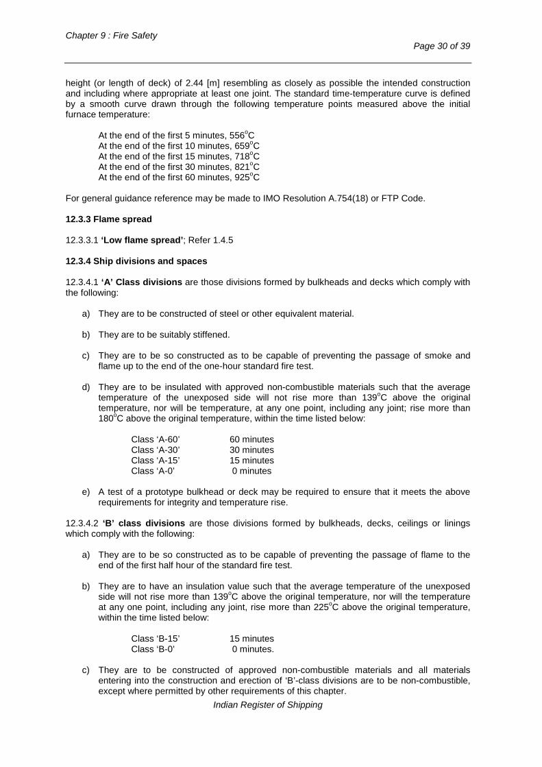
Chapter 9 : Fire Safety
Page 30 of 39
height (or length of deck) of 2.44 [m] resembling as closely as possible the intended construction and including where appropriate at least one joint. The standard time-temperature curve is defined by a smooth curve drawn through the following temperature points measured above the initial furnace temperature:
At the end of the first 5 minutes, 556oC At the end of the first 10 minutes, 659oC At the end of the first 15 minutes, 718oC At the end of the first 30 minutes, 821oC At the end of the first 60 minutes, 925oC
For general guidance reference may be made to IMO Resolution A.754(18) or FTP Code. 12.3.3 Flame spread 12.3.3.1 ‘Low flame spread’; Refer 1.4.5 12.3.4 Ship divisions and spaces 12.3.4.1 ‘A’ Class divisions are those divisions formed by bulkheads and decks which comply with the following:
a) They are to be constructed of steel or other equivalent material. b) They are to be suitably stiffened. c) They are to be so constructed as to be capable of preventing the passage of smoke and
flame up to the end of the one-hour standard fire test.
d) They are to be insulated with approved non-combustible materials such that the average temperature of the unexposed side will not rise more than 139oC above the original temperature, nor will be temperature, at any one point, including any joint; rise more than 180oC above the original temperature, within the time listed below:
Class ‘A-60’ 60 minutes Class ‘A-30’ 30 minutes Class ‘A-15’ 15 minutes Class ‘A-0’ 0 minutes
e) A test of a prototype bulkhead or deck may be required to ensure that it meets the above
requirements for integrity and temperature rise. 12.3.4.2 ‘B’ class divisions are those divisions formed by bulkheads, decks, ceilings or linings which comply with the following:
a) They are to be so constructed as to be capable of preventing the passage of flame to the end of the first half hour of the standard fire test.
b) They are to have an insulation value such that the average temperature of the unexposed
side will not rise more than 139oC above the original temperature, nor will the temperature at any one point, including any joint, rise more than 225oC above the original temperature, within the time listed below:
Class ‘B-15’ 15 minutes Class ‘B-0’ 0 minutes.
c) They are to be constructed of approved non-combustible materials and all materials
entering into the construction and erection of ‘B’-class divisions are to be non-combustible, except where permitted by other requirements of this chapter.
Indian Register of Shipping

Rules and Regulations for the Construction and Classification of Indian Coast Guard Ships - 2015
Page 31 of 39
d) A test of a prototype division may be required to ensure that it meets the above
requirements for integrity and temperature rise. 12.3.4.3 ‘Continuous ‘B’ Class ceilings or linings’ are those ‘B’ class ceilings or linings which terminate only at an ‘A’ or ‘B’ Class division. 12.3.4.4 ‘Accommodation spaces’ are those spaces used for public spaces, corridors, lavatories, cabins, offices, hospitals, cinemas, games and hobbies rooms, and pantries containing no cooking appliances and similar spaces. 12.3.4.5 ‘Service spaces’ are those used for galleys, pantries containing cooking appliances, stores, mail and specie rooms, store rooms, lockers, workshops other than those forming part of the machinery spaces and similar spaces and trunks to such spaces. 12.3.4.6 ‘Cargo spaces’ are all spaces used for cargo (including cargo oil tanks) and trunks to such spaces. 12.3.4.7 ‘Machinery spaces of Category A’ are those spaces and trunks to such spaces which contain:
a) Internal combustion machinery used for main propulsion; or b) Internal combustion machinery used for purposes other than main propulsion where such
machinery has in the aggregate a total power output of not less than 375 [kW]; or c) Any oil-fired boiler or oil fuel unit.
12.3.4.8 ‘Machinery spaces’ are all machinery spaces of Category ‘A’ and all other spaces containing propelling machinery, boilers, oil fuel units, steam and internal combustion engines, generators and major electrical machinery, oil filling stations, refrigerating, stabilizing, ventilation and air conditioning machinery and similar spaces and trunks to such spaces. 12.3.4.9 ‘Control stations’; Refer Chapter 1, 2.6.6 12.3.4.10 ‘Cargo area’ is that part of the Ship that contains cargo tanks, slop tanks and cargo pump rooms including pump rooms, cofferdams, ballast and void spaces adjacent to cargo tanks and also deck areas throughout the entire length and breadth of the part of the Ship over the above mentioned spaces. 12.3.4.11 ‘Main vertical zones’ are those sections into which the hull, superstructure and deck houses are divided by ‘A’ Class divisions, the mean length and width of which on any one deck does not, in general, exceed 40 [m]. 12.3.5 Equipment 12.3.5.1 ‘Oil fuel unit’ is the equipment used for the preparation of oil fuel for delivery to an oil-fired boiler, or equipment used for the preparation for delivery of heated oil to an internal combustion engine, and includes any oil pressure pumps, filters and heaters dealing with oil at a pressure of more than 1.8 [bar] gauge. 12.4 Fire pumps and fire main system 12.4.1 Application 12.4.1.1 Every Ship is to be provided with fire pumps, fire mains, hydrants and hoses complying as applicable with this section.
Indian Register of Shipping

Chapter 9 : Fire Safety
Page 32 of 39
12.4.2 Capacity of fire pumps 12.4.2.1 The total capacity of the main fire pumps is to be not less than four-thirds of the capacity of each bilge pump as per Chapter 11 as applicable 12.4.2.2 Any pump designated as a fire pump other than any emergency fire pump is to have a capacity not less than 80% of the total required capacity divided by the minimum number of required fire pumps and each such pump in any case is to be capable of delivering at least one jet of water. These fire pumps are to be capable of supplying the fire main system under the required conditions. 12.4.3 Fire pumps 12.4.3.1 In Ship of 150 tons gross and upwards, not less than two power pumps are to be provided, one of which is to be an independent pump. 12.4.3.2 In Ship of less than 150 tons gross, one power pump is to be available for fire-extinguishing service, if the service is restricted to harbour or river service, a suitable hand pump may be substituted for the power pump. 12.4.3.3 Sanitary, ballast, bilge or general service pumps may be accepted as fire pumps, provided that they are not normally used for pumping oil and that, if they are subject to occasional duty for the transfer or pumping of fuel oil, suitable changeover arrangements are fitted. 12.4.3.4 With one pump out of operation, simultaneous availability of pumps for bilge and fire duty is to be ensured. 12.4.3.5 If a fire in a category ‘A’ machinery space could put all the fire pumps out of action, there is to be an alternative means consisting of a fixed independently driven emergency fire pump which is to be capable of supplying at least one satisfactory jet of water. The pump and its location are to comply with 12.4.4. 12.4.3.6 Relief valves are to be provided in conjunction with all fire pumps if the pumps are capable of developing a pressure exceeding the design pressure of the water service pipes, hydrants and hoses. These valves are to be so placed and adjusted as to prevent excessive pressure in any part of the fire main system. 12.4.3.7 Where centrifugal pumps are provided in order to comply with this sub-section or 12.4.4, a non-return valve is to be fitted in the pipe connecting the pump to the fire main. 12.4.4 Emergency fire pumps 12.4.4.1 The emergency fire pump, its source of power and its sea connection are to be located in accessible positions outside the category ‘A’ machinery space referred to in 12.4.3.5. In Ship of less than 150 tons gross a manually operated pump will be accepted (see 12.4.6.1) provided it and its sea connection meet the requirements of this paragraph. 12.4.4.2 The sea valve is to be capable of being operated from a position near the pump. 12.4.4.3 The room where the emergency fire pump prime mover is located is to be illuminated from the emergency source of supply and is to be well ventilated. 12.4.4.4 If the emergency fire pump is required to supply water for a fixed fire-extinguishing system in the space where the main fire pumps are situated, it is to be capable of simultaneously supplying water to this system and the fire main at the required rates. 12.4.4.5 The emergency fire pump may also be used for other suitable purposes subject to approval in each case.
Indian Register of Shipping
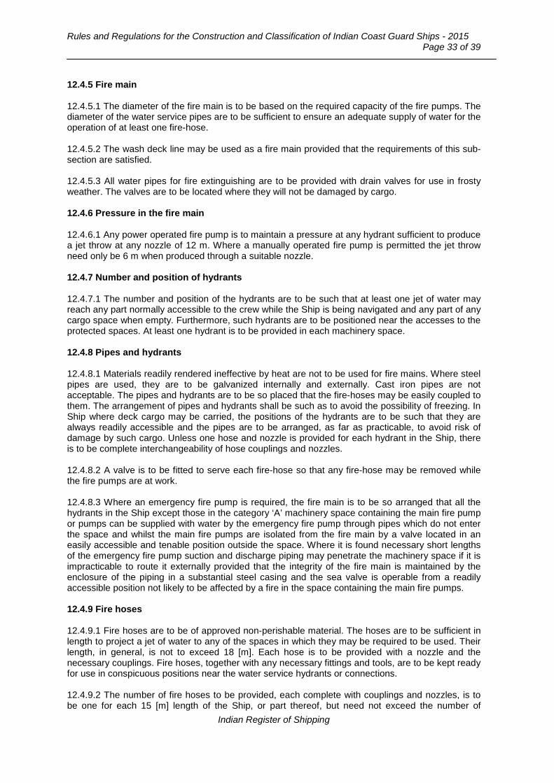
Rules and Regulations for the Construction and Classification of Indian Coast Guard Ships - 2015
Page 33 of 39
12.4.5 Fire main 12.4.5.1 The diameter of the fire main is to be based on the required capacity of the fire pumps. The diameter of the water service pipes are to be sufficient to ensure an adequate supply of water for the operation of at least one fire-hose. 12.4.5.2 The wash deck line may be used as a fire main provided that the requirements of this sub-section are satisfied. 12.4.5.3 All water pipes for fire extinguishing are to be provided with drain valves for use in frosty weather. The valves are to be located where they will not be damaged by cargo. 12.4.6 Pressure in the fire main 12.4.6.1 Any power operated fire pump is to maintain a pressure at any hydrant sufficient to produce a jet throw at any nozzle of 12 m. Where a manually operated fire pump is permitted the jet throw need only be 6 m when produced through a suitable nozzle. 12.4.7 Number and position of hydrants 12.4.7.1 The number and position of the hydrants are to be such that at least one jet of water may reach any part normally accessible to the crew while the Ship is being navigated and any part of any cargo space when empty. Furthermore, such hydrants are to be positioned near the accesses to the protected spaces. At least one hydrant is to be provided in each machinery space. 12.4.8 Pipes and hydrants 12.4.8.1 Materials readily rendered ineffective by heat are not to be used for fire mains. Where steel pipes are used, they are to be galvanized internally and externally. Cast iron pipes are not acceptable. The pipes and hydrants are to be so placed that the fire-hoses may be easily coupled to them. The arrangement of pipes and hydrants shall be such as to avoid the possibility of freezing. In Ship where deck cargo may be carried, the positions of the hydrants are to be such that they are always readily accessible and the pipes are to be arranged, as far as practicable, to avoid risk of damage by such cargo. Unless one hose and nozzle is provided for each hydrant in the Ship, there is to be complete interchangeability of hose couplings and nozzles. 12.4.8.2 A valve is to be fitted to serve each fire-hose so that any fire-hose may be removed while the fire pumps are at work. 12.4.8.3 Where an emergency fire pump is required, the fire main is to be so arranged that all the hydrants in the Ship except those in the category ‘A’ machinery space containing the main fire pump or pumps can be supplied with water by the emergency fire pump through pipes which do not enter the space and whilst the main fire pumps are isolated from the fire main by a valve located in an easily accessible and tenable position outside the space. Where it is found necessary short lengths of the emergency fire pump suction and discharge piping may penetrate the machinery space if it is impracticable to route it externally provided that the integrity of the fire main is maintained by the enclosure of the piping in a substantial steel casing and the sea valve is operable from a readily accessible position not likely to be affected by a fire in the space containing the main fire pumps. 12.4.9 Fire hoses 12.4.9.1 Fire hoses are to be of approved non-perishable material. The hoses are to be sufficient in length to project a jet of water to any of the spaces in which they may be required to be used. Their length, in general, is not to exceed 18 [m]. Each hose is to be provided with a nozzle and the necessary couplings. Fire hoses, together with any necessary fittings and tools, are to be kept ready for use in conspicuous positions near the water service hydrants or connections. 12.4.9.2 The number of fire hoses to be provided, each complete with couplings and nozzles, is to be one for each 15 [m] length of the Ship, or part thereof, but need not exceed the number of
Indian Register of Shipping

Chapter 9 : Fire Safety
Page 34 of 39
hydrants provided. This number does not include any hoses required in any engine room. If necessary, the number of hoses is to be increased so as to ensure that hoses in sufficient numbers are available and accessible at all times. 12.4.10 Nozzles 12.4.10.1 For the purpose of this chapter, standard nozzle sizes are to be 12 [mm], 16 [mm] or 19 [mm], or as near thereto as possible, so as to make full use of the maximum discharge capacity of the fire pumps. 12.4.10.2 For accommodation and service spaces, the nozzle size need not exceed 12 [mm]. 12.4.10.3 The size of nozzles intended for use in conjunction with a manually operated emergency fire pump need not exceed 9.5 [mm]. 12.4.10.4 For machinery spaces and exterior locations the nozzle size is not to be less than 12 [mm]. 12.4.10.5 All nozzles are to be of an approved dual purpose type (i.e. spray/jet type) incorporating a shut-off. 12.5 Fire extinguishers 12.5.1 Approved types 6.5.1.1 All fire-extinguishers are to comply with the requirements of Part 6, Chapter 8, Section 4 of Rules and Regulations for the Construction and Classification of Steel Ships. 12.5.2 Location 12.5.2.1 The extinguishers are to be stowed in readily accessible positions. 12.5.2.2 One of the portable fire-extinguishers intended for use in any space is to be stowed near the entrance to that space. 12.5.3 Portable fire-extinguishers in accommodation spaces, service spaces and control stations 12.5.3.1 Accommodation spaces, service spaces and control stations are to be provided with a sufficient number of portable fire extinguishers to ensure that at least one extinguisher will be readily available for use in every compartment. 12.6 Fire extinguishing arrangements in machinery spaces 12.6.1 Machinery space of category ‘A’ 12.6.1.1 Machinery spaces of category ‘A’ are to be provided with:
a) An approved foam type fire extinguisher of at least 45 [litre] capacity or equivalent to enable foam or its equivalent to be directed on to any part of the fuel and lubricating oil pressure systems, gearing and other fire hazards. Where the size of the machinery space makes the provision of a 45 [litre] fire extinguisher impracticable an additional number of portable extinguishers may be provided in lieu.
b) At least two portable foam extinguishers or equivalent. Where internal combustion
machinery is installed an additional portable extinguisher is to be provided for every 375 [kW] of power output, but the number of such additional extinguishers need not exceed five.
Indian Register of Shipping

Rules and Regulations for the Construction and Classification of Indian Coast Guard Ships - 2015
Page 35 of 39
12.6.1.2 Where the size of the machinery space precludes access under normal operating conditions, provisions is to be made to inject the extinguishing medium into the machinery space from an external location whilst maintaining the fire integrity of the machinery space boundaries. 12.6.2 Machinery spaces in service ships which are constructed mainly or wholly of fibre-reinforced plastic or wood 12.6.2.1 Machinery spaces containing internal combustion machinery, in addition to compliance with 12.6.1 are to be provided with any one of the fixed fire-extinguishing systems as per Part 6, Chapter 8, Section 5 of the Rules and Regulations for the Construction and Classification of Steel Ships, except that use of halon as fire extinguishing medium is not permitted. 12.6.3 Fire-extinguishing appliances in other machinery spaces 12.6.3.1 Where a fire hazard exists in any machinery space for which no specific provisions for fire extinguishing appliances are prescribed in 12.6.1 and 12.6.2 there are to be provided in or adjacent to, that space a satisfactory number of approved portable fire extinguishers or other approved means of fire extinction. 12.6.4 Fixed fire extinguishing systems not required by this section 12.6.4.1 Where a fixed fire extinguishing system not required by this section is installed, the arrangement will be specially considered. 12.6.5 Machinery spaces with electrical installations 12.6.5.1 Machinery spaces with electrical installations are to be provided with one or more extinguishers suitable for extinguishing electrical fire as deemed necessary. One or more of the fire extinguishers required by this section may be of the type required by this paragraph. 12.7 Special arrangements in machinery spaces 12.7.1 This section applies to machinery spaces of category A and where necessary to other machinery spaces 12.7.1.1 The number of openings to machinery spaces are to be reduced to a minimum consistent with the needs of ventilation and the proper and safe working of the Ship. 12.7.1.2 Openings are to be provided with closing appliances constructed so as to maintain the fire integrity of the machinery space boundaries. 12.7.1.3 Windows are not to be fitted in machinery space boundaries. This does not preclude the use of glass in control rooms within machinery spaces. 12.7.1.4 Means of control are to be provided for:
a) closure of openings which normally allow exhaust ventilation and closure of ventilator dampers;
b) permitting the release of smoke; c) closing power operated doors or actuating release mechanism on doors other than power
operated water tight doors; d) stopping ventilating fans; and e) stopping forced and induced draught fans, oil fuel transfer pumps, oil fuel unit pumps and
other similar fuel pumps.
12.7.1.5 The controls required in 12.7.1.4 and Chapter 11, Section 2 are to be located outside the space concerned, where they will not be cut off in the event of fire in the space they serve.
Indian Register of Shipping

Chapter 9 : Fire Safety
Page 36 of 39
12.8 Arrangement of oil fuel, lubricating oil and other flammable oils 12.8.1 Oil fuel arrangements 12.8.1.1 In Ship in which oil fuel is used, the arrangements for the storage, distribution and utilization of the oil fuel are to be such as to ensure the safety of the Ship and persons on board. For details see Chapter 11, Section 2 12.8.1.2 Oil fuel tanks situated within the boundaries of machinery spaces of category A are not to contain oil fuel having a flash-point of less than 60oC. 12.8.2 Prohibition of carriage of flammable oils in forepeak tanks 12.8.2.1 Oil fuel, lubricating oil and other flammable oils are not to be carried in forepeak tanks. 12.9 Fireman’s outfit/axe 12.9.1 Application 12.9.1.1 All Ship having enclosed spaces which are normally accessible are to carry at least two fireman’s outfits complying with the requirements of Section 10. Special consideration will be given where this is considered to be excessive due to the general arrangement. 12.9.1.2 Every Ship is to be provided with at least one fireman’s axe in easily accessible location. 12.10 Miscellaneous items 12.10.1 Penetrations 12.10.1.1 Where ‘A’ class divisions are penetrated for the passage of electric cables, pipes, trunks, ducts, etc., or for girders, beams or other structural members, arrangements are to be made to ensure that the fire resistance is not impaired. 12.10.1.2 Where ‘B’ class divisions are penetrated for the passage of electric cables, pipes, trunks, ducts, etc., or for the fitting of ventilation terminals, lighting fixtures and similar devices, arrangements are to be made to ensure that the fire resistance is not impaired. 12.10.2 Materials 12.10.2.1 Pipes penetrating ‘A’ or ‘B’ class divisions are to be of approved materials having regard to the temperature such divisions are required to withstand. 12.10.2.2 Pipes conveying oil or combustible liquids through accommodation and service spaces are to be of approved materials having regard to the fire risk. 12.10.2.3 Materials readily rendered ineffective by heat are not to be used for overboard scuppers, sanitary discharges, and other outlets which are close to the water line and where the failure of the material in the event of fire would give rise to danger of flooding. 12.10.3 Waste receptacles 12.10.3.1 All waste receptacles are to be constructed of non-combustible materials with no openings in the sides or bottom. 12.10.4 Surface of insulation 12.10.4.1 In spaces where penetration of oil product is possible, the surface of insulation is to be impervious to oil or oil vapours. Insulation boundaries are to be arranged to avoid immersion in oil spillages so far as is practicable.
Indian Register of Shipping
Rules and Regulations for the Construction and Classification of Indian Coast Guard Ships - 2015
Page 37 of 39
12.10.5 Foam concentrates 12.10.5.1 Foam concentrates carried for use in fixed foam fire extinguishing systems are to be of an approved type. They are to be tested at least twice during each five year period to verify that they remain fit for service. Evidence in the form of a report from the foam manufacturer or an independent laboratory will be accepted. 12.10.6 Protection of paint lockers and flammable liquid lockers 12.10.6.1 Paint lockers and flammable liquid lockers of deck area 4 [m2] or over, are to be provided with a fixed fire extinguishing system enabling the crew to extinguish a fire without entering the space. One of the following systems is to be provided:
a) A carbon dioxide system designed for 40 per cent of the gross volume of the space. b) A dry powder system designed to discharge 0.5 [kg powder/ cubic metre] of gross volume of
the space. c) A water spray system designed to give coverage of five [lit/m2] of deck area per minute.
Water spray systems may be connected to the fire main. Consideration will be given to the acceptance of other arrangements, which provide equivalent protection. 12.10.6.2 Lockers having a deck area less than 4 [m2] may be protected by carbon dioxide or dry powder portable extinguishers located near the entrance to the locker. 12.10.7 Fire control plan 12.10.7.1 Fire control plans are to meet the requirements of Section 9. 12.11 Fire safety measures for the Ship 12.11.1 Structure 12.11.1.1 The hull, superstructure, structural bulkheads, decks and deckhouses are to be constructed of steel or other equivalent material. For the purpose of applying the definition of steel or other equivalent material, the applicable fire exposure is to be according to the integrity and insulation standards given in 12.11.1.3 and 12.11.1.4, for example where divisions are permitted to have ‘B-0’ fire integrity, the ‘applicable fire exposure’ is to be one half-hour. 12.11.1.2 Crowns and casings of machinery spaces of Category ‘A’ and lockers containing paint and flammable liquid are to be ‘A’ class divisions and adequately insulated to take account of the fire risk in adjacent spaces. Openings therein, if any, are to be suitably arranged and protected to prevent the spread of fire. 12.11.1.3 Decks and bulkheads separating machinery spaces other than category A, from control stations, from each other and from accommodation and service spaces are to be constructed to B-15 class standard. In addition, machinery space boundaries are to prevent the passage of smoke. Doors and other openings in such bulkheads and decks are to be constructed so as to provide protection in resisting fire, equivalent to the surrounding structure. 12.11.1.4 Bulkheads of corridors serving accommodation spaces, service spaces and control stations are to extend from deck to deck unless continuous ‘B’ class ceilings are fitted on both sides of the bulkhead in which case the bulkhead may terminate at the continuous ceiling and, together with decks, they are to be constructed to at least ‘B-0’ standard. Doors and other openings in such bulkheads and decks are to be constructed so as to provide protection in resisting fire equivalent to the surrounding structure.
Indian Register of Shipping

Chapter 9 : Fire Safety
Page 38 of 39
12.11.1.5 Interior stairways serving machinery spaces, accommodation spaces, service spaces or control stations are to be of steel or other equivalent material. 12.11.1.6 The number of openings in the bulkheads and decks referred to in 12.11.1.3 and 12.11.1.4 above are to be as few as reasonably practicable. 12.11.1.7 Primary deck coverings within accommodation spaces, service spaces and control stations are to be of a type which will not readily ignite. 12.11.1.8 Non-combustible insulation is to be fitted in machinery spaces and other compartments containing high fire risks. Elsewhere combustible insulation may be used provided it is totally enclosed by cladding, the exposed surfaces of which have low flame spread characteristics. 12.11.1.9 Paints, varnishes and other finishes used on exposed interior surfaces are to be of low flame spread type, that is, to adequately restrict the spread of flame on such surfaces. 12.11.1.10 Paints, varnishes and other finishes used on exposed interior surfaces are not to be capable of producing excessive quantities of smoke or toxic gases or vapours. 12.11.2 Ventilation systems 12.11.2.1 Ventilation fans are to be capable of being stopped and main inlets and outlets of ventilation systems closed from outside the spaces being served. 12.11.2.2 Ventilation openings may be fitted in the lower parts of the doors in corridor bulkheads. Ventilation grills are to be of non-combustible material. The total net area of any such openings is not to exceed 0.05 [m2]. 12.11.2.3 Ventilation ducts for main machinery spaces are not in general to pass through accommodation spaces, service spaces or control station unless the ducts are constructed of steel and arranged to preserve the integrity of the division. 12.11.2.4 Ventilation ducts of accommodation spaces, service spaces or control stations are not in general to pass through main machinery spaces unless the ducts are constructed of steel and arranged to preserve the integrity of the division. 12.11.2.5 Store-rooms containing highly flammable products are to be provided with ventilation arrangements which are separate from other ventilation systems. Ventilation is to be arranged at high and low levels and the inlets and outlets of ventilators should be positioned in safe areas and fitted with spark arresters. 12.11.2.6 Ventilation systems serving machinery spaces are to be independent of systems serving other spaces. 12.11.3 Means of escape 12.11.3.1 Stairways, ladders and corridors serving crew spaces and other spaces to which the crew normally have access are to be arranged so as to provide ready means of escape to a deck from which disembarkation may be effected. 12.11.3.2 Where reasonable and practicable and having regard to the number of crew and size of space, at least two means of escape, one of which may be the normal means of access, as widely separated as possible are to be provided from each section of accommodation and service spaces. Normal means of access to accommodation and service spaces below the open deck is to be arranged so that it is possible to reach the open deck without passing through intervening spaces containing a possible source of fire. The second means of escape may be through portholes or hatches of adequate size and preferably leading directly to the open deck.
Indian Register of Shipping

Rules and Regulations for the Construction and Classification of Indian Coast Guard Ships - 2015
Page 39 of 39
12.11.3.3 Except where the smallness of the machinery spaces makes it impracticable at least two means of escape, one of which may be the normal means of access are to be provided by steel ladders and should be as widely separated as possible. 12.11.4 Arrangements for gaseous fuel for domestic purposes 12.11.4.1 Where gaseous fuel is used for domestic purposes the arrangements for the storage, distribution and utilization of the fuel is to be such that, having regard to the hazards of fire and explosion which the use of such fuel may entail, the safety of the Ship and the persons on board is preserved. The installation is to be in accordance with recognized National or International Standards.
End of Chapter
Indian Register of Shipping
Rules and Regulations for the Construction and Classification of Indian Coast Guard Ships - 2015 Page 1 of 21
___________________________________________________________________________________
Chapter 10
Piping Design Requirements
Contents Section
1 General
2 Carbon and Low Alloy Steel Pipes and Fittings
3 Copper and Copper Alloy Pipes and Fittings
4 Cast Iron Pipes and Fittings
5 Plastic Pipes and Fittings
6 Flexible Hoses
7 Expansion Bellows
8 Hydraulic Tests on Pipes and Fittings
Section 1
General
1.1 Scope 1.1.1 The requirements of this Chapter apply to the design and construction of piping systems, including pipe fittings and valves forming parts of such systems for the following services:
- Air, vapour, gas - Water, lubricating oil, fuel oil, - Hydraulic fluid systems for steering gear /CPP /thruster for propulsion or dynamic positioning
/windlass machinery /water tight, bow, stern, side and bulkhead doors /valve control systems etc.
- Toxic gas and liquids, - Open ended lines such as drains; overflows, vents and boiler escape pipes.
1.1.2 The requirements of this Chapter do not cover exhaust pipes from internal combustion engines and gas turbines, and pipes forming integral part of a boiler. 1.1.3 Hydraulic fluid systems other than those mentioned at 1.1.1 will be specially considered. 1.1.4 The provisions of this chapter do not address pipe size selection in respect of adequacy to satisfy design requirements for flow rates and/or heat transfer in piping systems. 1.2 Classes of pipes 1.2.1 For the purpose of testing, type of joints to be adopted, heat treatment and welding procedure, piping systems are divided into three classes, as given in Table 1.2.1.
Indian Register of Shipping

Chapter 10 : Piping Design Requirements Page 2 of 10
Table 1.2.1 : Classes of piping systems 3,4
Piping system Class I Class II Class III
Toxic or corrosive media Without special safeguards Not to be used Not to be used
a) Flammable media heated above flash point2
b) Flammable media having flash point below 60°C2
c) Liquefied gas
Without special safeguards With special safeguards1 Not to be used
Steam P > 16 or T > 300 16 ≥ P > 7 and 300 ≥ T > 170 P ≤ 7 and T ≤ 170 Thermal Oil P > 16 or T > 300 16 ≥ P > 7 and 300 ≥ T > 150 P ≤ 7 and T ≤ 150 Fuel oil + Lubricating oil + Flammable hydraulic oil P > 16 or T > 150 16 ≥ P > 7 and 150 ≥ T > 60 P ≤ 7 and T ≤ 60
Other media5 including water, air, gases, non-flammable hydraulic oil
P > 40 or T > 300 40 ≥ P > 16 and 300 ≥ T > 200 P ≤ 16 and T ≤ 200
Notes: 1 Safeguards for reducing leakage possibility and limiting its consequences will be specially
considered e.g. leading pipes in positions where leakage of internal fluids will not cause a potential hazard or damage to surrounding areas or by the usage of pipe ducts, shielding, screening etc.
2 Cargo oil pipes belong to Class III piping systems. 3 P = Design pressure in bar as defined in 1.3 4 T = Design temperature in °C as defined in 1.4. 5 For open ended pipes (drains, overflow, vents, exhaust gas lines, boiler escape lines, etc.)
irrespective of the temperature, Class III pipes may be used.
1.3 Design pressure 1.3.1 The design pressure, P, is the maximum permissible working pressure and is to be not less than the highest set pressure of the safety valve or relief valve. For oil fuel pipes the design pressure is to be taken in accordance with Table 1.3.1. For gaseous fuel, the design pressure will be specially considered. 1.3.2 In water tube boiler installations, the design pressure for steam piping between the boiler and integral superheater outlet is to be taken as the design pressure of the boiler, i.e. not less than the highest set pressure of any safety valve on the boiler drum. For piping leading from the superheater outlet, the design pressure is to be taken as the highest set pressure of the superheater safety valves. 1.3.3 The design pressure of feed piping and other piping on the discharge from pumps is to be taken as the pump pressure at full rated speed against a shut valve. Where a safety valve or other protective device is fitted to restrict the pressure to a lower value than the shut valve load, the design pressure is to be the highest set pressure of the protective device.
Indian Register of Shipping

Rules and Regulations for the Construction and Classification of Indian Coast Guard Ships - 2015 Page 3 of 21
___________________________________________________________________________________
Table 1.3.1 : Definition of the design pressure for fuel oil systems
Working temperature
Working Pressure (WP)
T ≤ 60°C T > 60°C
WP ≤ 7 bar 3 bar or max. working pressure, whichever is greater
3 bar or max. working pressure, whichever is greater
WP > 7 bar Max. working pressure 14 bar or max. working pressure, whichever is greater
1.4 Design temperature 1.4.1 The design temperature is to be taken as the maximum temperature of the internal fluid, but in no case it is to be taken as less than 50°C. For special cases the design temperature will be specially considered. 1.4.2 In the case of pipes for superheated steam, the temperature is to be taken as the designed operating steam temperature for the pipeline, provided that the temperature at the superheater outlet is closely controlled. Where temperature fluctuations exceeding 15°C above the designed temperature are to be expected in normal service, the steam temperature to be used for determining the allowable stress is to be increased by the amount of this excess. 1.5 Design symbols 1.5.1 The symbols used in this Chapter are defined as follows: a = percentage negative manufacturing tolerance on thickness; b = bending allowance [mm]; c = corrosion allowance [mm]; D = outside diameter of pipe [mm] (see 1.5.2); d = inside diameter of pipe [mm] (see 1.5.3); e = weld efficiency factor (see 1.5.4); P = design pressure, in bar; Pt = hydraulic test pressure, in bar; R = radius of curvature of a pipe bend at the centreline of the pipe [mm]; T = design temperature, in °C; t = the minimum thickness of a straight pipe [mm], including corrosion allowance and negative tolerance, where applicable; tb = the minimum thickness of a straight pipe to be used for a pipe bend [mm]; including bending allowance, corrosion allowance and negative tolerance, where applicable; K = maximum permissible design stress [N/mm2]. 1.5.2 The outside diameter, D, is subject to manufacturing tolerances, but these tolerances are not to be used in the calculations.
Indian Register of Shipping

Chapter 10 : Piping Design Requirements Page 4 of 10
1.5.3 The inside diameter, d, is different from the nominal size. The nominal size is an accepted designation associated with outside diameters of standard rolling sizes. 1.5.4 The weld efficiency factor, e, is to be taken as 1.0 for seamless and electric resistance and induction welded steel pipes delivered by manufacturers approved for making welded pipes which are considered to be equivalent to seamless pipes. Where other methods of pipe manufacture are proposed, the value of e will be specially considered. 1.6 Heat treatment 1.6.1 Method of heat treatment and means of temperature control and recording are to be in accordance with the approved drawings and to the satisfaction of Surveyors. 1.7 Minimum thickness of pipes and bends 1.7.1 The minimum thickness, t, of straight pipes is to be determined by the following formula when ratio of outside-diameter to inside-diameter does not exceed the value 1.7:-
][mma100
100cP20Ke
PDt−
+
+=
where, P, D, e and a are defined in 1.5.1.
Value of “c” is to be obtained from Sec.2, Table 2.2.1 for carbon and low alloy steel pipes and fittings or from Sec.3, Table 3.2.3 for copper and copper alloys pipes and fittings. The maximum permissible design stress, K, is to be taken as the lowest of the following values:-
1/or1.6S
or 2.7R
or 1.6E
K 000,100/1R20t σ=
where, σ1/100,000/1 = average stress [N/mm2] to produce 1% creep in 100,000 hrs at the design temperature. Et = specified minimum lower yield or 0.2 per cent proof stress at the design temperature R20 = specified minimum tensile strength at ambient temperature SR = average stress to produce rupture in 100,000 hours at the design temperature.
Value of K may be obtained from Sec.2, Table 2.1.1 and Table 2.1.2 for carbon and low alloy steel pipes and fittings or from Sec.3, Table 3.2.1 for copper and copper alloys pipes and fittings. 1.7.2 Where it is proposed to use, for high temperature service, alloy steels other than those detailed in Sec.2, particulars of the tube sizes, design conditions and appropriate national or proprietary material specifications are to be submitted for consideration. 1.7.3 The minimum thickness, tb, of a straight steel pipe to be used for a pipe bend is to be determined by the following formula, except where it can be demonstrated that the use of a thickness less than tb would not reduce the thickness below 't' at any point after bending:-
][mma100
100cbP20Ke
PDt b −
++
+=
Indian Register of Shipping

Rules and Regulations for the Construction and Classification of Indian Coast Guard Ships - 2015 Page 5 of 21
___________________________________________________________________________________
where, P, D, R, e, b and a are defined in 1.5.1; K and c are defined in 1.7.1;
][mmP20Ke
PD2.5R
D b
+=
In general, R, is to be not less than 3D. Where, this is not practicable, the thickness of pipe is to be specially approved. 1.7.4 Notwithstanding the requirements of 1.7.1 and 1.7.3, the minimum thickness of pipes is not to be less than that indicated in Sec.2 or 3, as applicable. For threaded pipes, where permitted, the minimum thickness is to be measured at the bottom of the thread. 1.8 Flanges 1.8.1 The dimensions of flanges and related bolts, gaskets are to be chosen in accordance with recognised national/international standards. For special applications, the dimensions of the flanges and related bolts, will be specially considered. 1.8.2 Gaskets are to be suitable for the medium being conveyed under design pressure and temperature conditions and their dimensions and configurations are to be in accordance with a recognized standard and for the intended service. 1.9 Materials 1.9.1 Materials for ferrous castings and forgings of Class I and Class II piping systems are to be produced at Works approved by IRS and are in general to be tested in accordance with the requirements of Pt.2 of the Rules. 1.9.2 The manufacturer's test certificate for materials of valves and fittings will be accepted in lieu of the IRS certificate provided the maximum conditions are less than given in Table 1.9.1. 1.9.3 Pipes and bodies of valves, intended to be fitted on ship's side and bottom or on collision bulkhead, are to comply with the requirements of Class II piping systems. 1.9.4 Materials for Class III piping systems may be manufactured and tested in accordance with the requirements of an acceptable national/ international standard.
Table 1.9.1 : Maximum conditions for valves and fittings for which manufacturer's test
certificate is acceptable
Material Working temp.°C DN = Nominal Diameter [mm] Pw = Working Pressure in bar
Carbon and low alloy steel Spheroidal or nodular cast iron
< 300
DN < 50 or Pw x DN < 2500
Copper alloy < 200 DN < 50 or Pw x DN < 1500
Indian Register of Shipping

Chapter 10 : Piping Design Requirements Page 6 of 10
Section 2
Carbon and Low Alloy Steel Pipes and Fittings
2.1 Materials 2.1.1 Pipes having forge butt welded longitudinal seams are not to be used for oil fuel systems, for heating coils in oil tanks, or for pressures exceeding 4.0 bar. 2.1.2 Steel pipes, valves and fittings may be used within the temperature limits indicated in Table 2.1.1 and Table 2.1.2. Where rimmed steel is used for pipes manufactured by electric resistance or induction welding processes, the design temperature is limited to 400°C.
Table 2.1.1 : Carbon and carbon-manganese steel pipes
Specified
min. tensile
strength [N/mm2]
Maximum permissible stress [N/mm2] Maximum design temperature °C
50 100 150 200 250 300 350 400 410 420 430 440 450 320 107 105 99 92 78 62 57 55 55 54 54 54 49 360 120 117 110 103 91 76 69 68 68 68 64 56 49 410 136 131 124 117 106 93 86 84 79 71 64 56 49 460 151 146 139 132 122 111 101 99 98 85 73 62 53 490 160 156 148 141 131 121 111 109 98 85 73 62 53
Table 2.1.2 : Alloy steel pipes
Type of steel Specified
min. tensile strength [N/mm2]
Minimum permissible stress [N/mm2]
Maximum design temperature °C 50 100 200 300 350 400 440 450 460 470
1 Cr 1/2 Mo 440 159 150 137 114 106 102 101 101 100 99 2 1/4 Cr 1 Mo annealed 410 76 67 57 50 47 45 44 43 43 42
2 1/4 Cr 1 Mo normalised and tempered (Note 1)
490 167 163 153 144 140 136 130 128 127 116
2 1/4 Cr 1 Mo normalised and tempered (Note 2)
490 167 163 153 144 140 136 130 122 114 105
1/2 Cr 1/2 Mo 1/4 V 460 166 162 147 120 115 111 106 105 103 102
Maximum design temperature °C
480 490 500 510 520 530 540 550 560 570
1 Cr 1/2 Mo 440 98 97 91 76 62 51 42 34 27 22 2 1/4 Cr 1 Mo annealed 410 42 42 41 41 41 40 40 40 37 32
2 1/4 Cr 1 Mo normalised and tempered (Note 1)
490 106 96 86 76 67 58 49 43 37 32
2 1/4 Cr 1 Mo normalised and tempered (Note 2)
490 96 88 79 72 64 56 49 43 37 32
1/2 Cr 1/2 Mo 1/4 V 460 101 99 97 94 82 72 62 53 45 37
Indian Register of Shipping
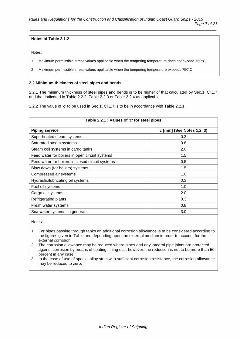
Rules and Regulations for the Construction and Classification of Indian Coast Guard Ships - 2015 Page 7 of 21
___________________________________________________________________________________
Notes of Table 2.1.2 Notes: 1 Maximum permissible stress values applicable when the tempering temperature does not exceed 750°C. 2 Maximum permissible stress values applicable when the tempering temperature exceeds 750°C.
2.2 Minimum thickness of steel pipes and bends 2.2.1 The minimum thickness of steel pipes and bends is to be higher of that calculated by Sec.1, Cl.1.7 and that indicated in Table 2.2.2, Table 2.2.3 or Table 2.2.4 as applicable. 2.2.2 The value of 'c' to be used in Sec.1, Cl.1.7 is to be in accordance with Table 2.2.1.
Table 2.2.1 : Values of 'c' for steel pipes
Piping service c [mm] (See Notes 1,2, 3) Superheated steam systems 0.3 Saturated steam systems 0.8 Steam coil systems in cargo tanks 2.0 Feed water for boilers in open circuit systems 1.5 Feed water for boilers in closed circuit systems 0.5 Blow down (for boilers) systems 1.5 Compressed air systems 1.0 Hydraulic/lubricating oil systems 0.3 Fuel oil systems 1.0 Cargo oil systems 2.0 Refrigerating plants 0.3 Fresh water systems 0.8 Sea water systems, in general 3.0 Notes: 1 For pipes passing through tanks an additional corrosion allowance is to be considered according to
the figures given in Table and depending upon the external medium in order to account for the external corrosion.
2 The corrosion allowance may be reduced where pipes and any integral pipe joints are protected against corrosion by means of coating, lining etc., however, the reduction is not to be more than 50 percent in any case.
3 In the case of use of special alloy steel with sufficient corrosion resistance, the corrosion allowance may be reduced to zero.
Indian Register of Shipping
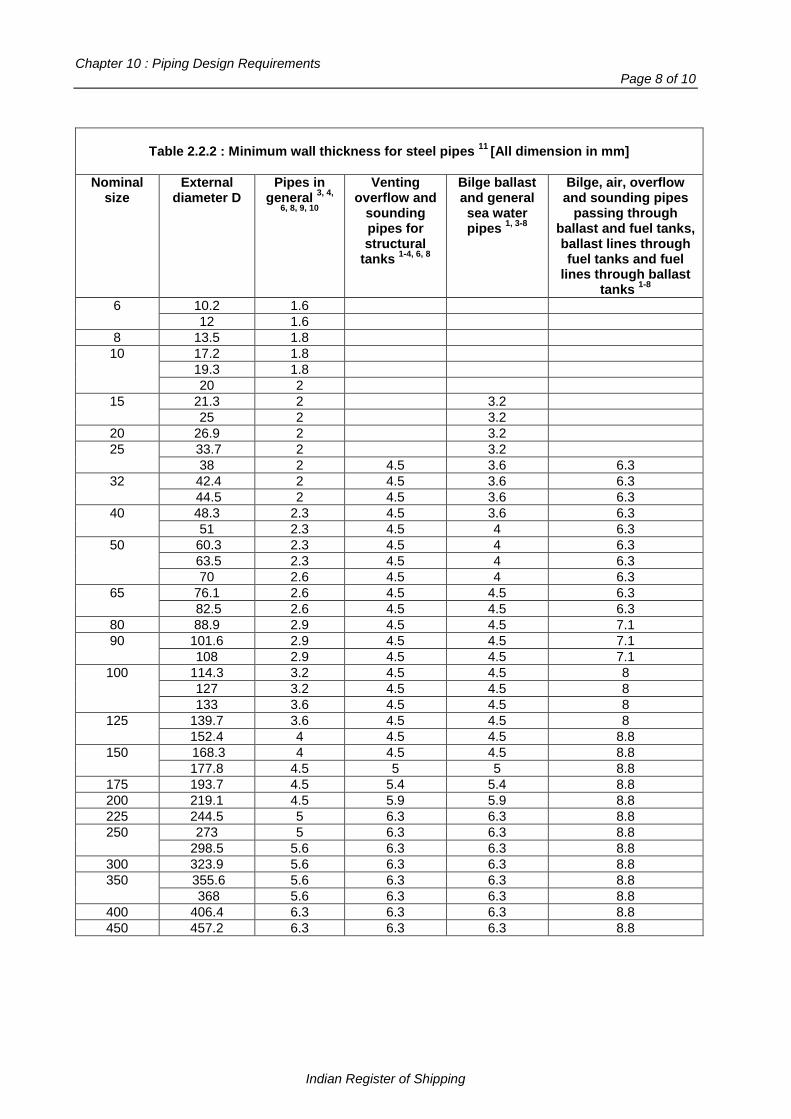
Chapter 10 : Piping Design Requirements Page 8 of 10
Table 2.2.2 : Minimum wall thickness for steel pipes 11 [All dimension in mm]
Nominal size
External diameter D
Pipes in general 3, 4,
6, 8, 9, 10
Venting overflow and
sounding pipes for structural
tanks 1-4, 6, 8
Bilge ballast and general sea water pipes 1, 3-8
Bilge, air, overflow and sounding pipes
passing through ballast and fuel tanks, ballast lines through fuel tanks and fuel
lines through ballast tanks 1-8
6 10.2 1.6 12 1.6
8 13.5 1.8 10 17.2 1.8
19.3 1.8 20 2
15 21.3 2 3.2 25 2 3.2
20 26.9 2 3.2 25 33.7 2 3.2
38 2 4.5 3.6 6.3 32 42.4 2 4.5 3.6 6.3
44.5 2 4.5 3.6 6.3 40 48.3 2.3 4.5 3.6 6.3
51 2.3 4.5 4 6.3 50
60.3 2.3 4.5 4 6.3 63.5 2.3 4.5 4 6.3 70 2.6 4.5 4 6.3
65 76.1 2.6 4.5 4.5 6.3 82.5 2.6 4.5 4.5 6.3
80 88.9 2.9 4.5 4.5 7.1 90 101.6 2.9 4.5 4.5 7.1
108 2.9 4.5 4.5 7.1 100 114.3 3.2 4.5 4.5 8
127 3.2 4.5 4.5 8 133 3.6 4.5 4.5 8
125 139.7 3.6 4.5 4.5 8 152.4 4 4.5 4.5 8.8
150
168.3 4 4.5 4.5 8.8 177.8 4.5 5 5 8.8
175 193.7 4.5 5.4 5.4 8.8 200 219.1 4.5 5.9 5.9 8.8 225 244.5 5 6.3 6.3 8.8 250 273 5 6.3 6.3 8.8
298.5 5.6 6.3 6.3 8.8 300 323.9 5.6 6.3 6.3 8.8 350 355.6 5.6 6.3 6.3 8.8
368 5.6 6.3 6.3 8.8 400 406.4 6.3 6.3 6.3 8.8 450 457.2 6.3 6.3 6.3 8.8
Indian Register of Shipping
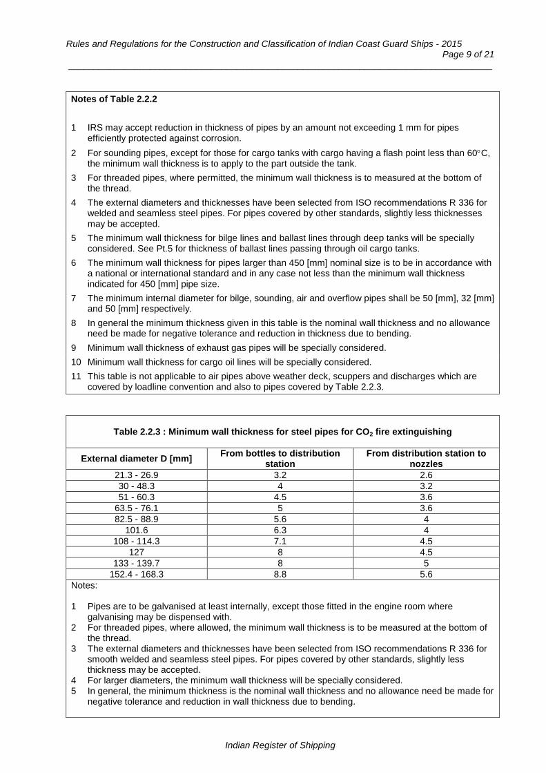
Rules and Regulations for the Construction and Classification of Indian Coast Guard Ships - 2015 Page 9 of 21
___________________________________________________________________________________
Notes of Table 2.2.2 1 IRS may accept reduction in thickness of pipes by an amount not exceeding 1 mm for pipes
efficiently protected against corrosion. 2 For sounding pipes, except for those for cargo tanks with cargo having a flash point less than 60°C,
the minimum wall thickness is to apply to the part outside the tank. 3 For threaded pipes, where permitted, the minimum wall thickness is to measured at the bottom of
the thread. 4 The external diameters and thicknesses have been selected from ISO recommendations R 336 for
welded and seamless steel pipes. For pipes covered by other standards, slightly less thicknesses may be accepted.
5 The minimum wall thickness for bilge lines and ballast lines through deep tanks will be specially considered. See Pt.5 for thickness of ballast lines passing through oil cargo tanks.
6 The minimum wall thickness for pipes larger than 450 [mm] nominal size is to be in accordance with a national or international standard and in any case not less than the minimum wall thickness indicated for 450 [mm] pipe size.
7 The minimum internal diameter for bilge, sounding, air and overflow pipes shall be 50 [mm], 32 [mm] and 50 [mm] respectively.
8 In general the minimum thickness given in this table is the nominal wall thickness and no allowance need be made for negative tolerance and reduction in thickness due to bending.
9 Minimum wall thickness of exhaust gas pipes will be specially considered. 10 Minimum wall thickness for cargo oil lines will be specially considered. 11 This table is not applicable to air pipes above weather deck, scuppers and discharges which are
covered by loadline convention and also to pipes covered by Table 2.2.3.
Table 2.2.3 : Minimum wall thickness for steel pipes for CO2 fire extinguishing
External diameter D [mm] From bottles to distribution station
From distribution station to nozzles
21.3 - 26.9 3.2 2.6 30 - 48.3 4 3.2 51 - 60.3 4.5 3.6
63.5 - 76.1 5 3.6 82.5 - 88.9 5.6 4
101.6 6.3 4 108 - 114.3 7.1 4.5
127 8 4.5 133 - 139.7 8 5
152.4 - 168.3 8.8 5.6 Notes: 1 Pipes are to be galvanised at least internally, except those fitted in the engine room where
galvanising may be dispensed with. 2 For threaded pipes, where allowed, the minimum wall thickness is to be measured at the bottom of
the thread. 3 The external diameters and thicknesses have been selected from ISO recommendations R 336 for
smooth welded and seamless steel pipes. For pipes covered by other standards, slightly less thickness may be accepted.
4 For larger diameters, the minimum wall thickness will be specially considered. 5 In general, the minimum thickness is the nominal wall thickness and no allowance need be made for
negative tolerance and reduction in wall thickness due to bending.
Indian Register of Shipping

Chapter 10 : Piping Design Requirements Page 10 of 10
Table 2.2.4 : Minimum wall thickness for austenitic stainless steel pipes
External diameter D [mm]
Minimum wall thickness [mm]
External diameter D [mm]
Minimum wall thickness [mm]
10.2 to 17.2 1.0 219.1 2.6 21.3 to 48.3 1.6 273.0 2.9 60.3 to 88.9 2.0 323.9 to 406.4 3.6
114.3 to 168.3 2.3 Over 406.4 4.0 Note : Diameters and thicknesses according to national or international standard may be accepted.
2.3 Types of connection 2.3.1 Pipe lengths may be joined by - screwed-on or welded on bolted flanges - Butt welds between pipes or between pipes and valve chests or other fittings - Socket weld joints - Threaded sleeve joints - Mechanical joints. and are to be to a recognized standard or of a design proven to be suitable for the intended purpose. 2.4 Flange connections 2.4.1 Flange attachments are to be in accordance with recognized national or international standards applicable to piping system keeping in view the boundary fluids, design pressure and temperature conditions, external or cyclic loading and location. 2.4.2 Flanges may be cut from plates or may be forged or cast. The material is to be suitable for the design temperature. Flanges may be attached to the branches by screwing and expanding or by welding. Alternative methods of flange attachment may be accepted provided details are submitted for consideration. 2.4.3. Examples of accepted flanged connections and their uses are given in Fig.2.4.1 and Table 2.4.1 respectively. 2.4.4 Where flanges are secured by screwing, as indicated in Fig.2.4.1, the pipe and flange are to be screwed with a vanishing thread and the diameter of the screwed position of pipe over the thread is not to be appreciably less than the outside diameters of the unscrewed pipe. After the flange has been screwed hard home, the pipe is to be expanded into the flange. The vanishing thread on a pipe is to be not less than three pitches in length, and the diameter at the root of the thread is to increase uniformly from the standard root diameter to the diameter at the top of the thread. This may be produced by suitably grinding the dies, and the flange should be tapered out to the same formation.
Table 2.4.1 : Type of flange connections
Class of piping t°C
Steam Lub. and fuel oil Other media
Typical flange application
Typical flange application
Typical flange application
I 1) > 400 A A - B A ≤ 400 A - B2 A - B II > 250 A - B - C A - B - C A - B - C ≤ 250 A - B - C - D - E A - B - C - D - E
III A - B - C - D - E A - B -C - E A - B - C - D - E 1 For Class I only one condition is sufficient. 2 Type B for outer diameter < 150 [mm] only.
Indian Register of Shipping

Rules and Regulations for the Construction and Classification of Indian Coast Guard Ships - 2015 Page 11 of 21
___________________________________________________________________________________
2.5 Threaded sleeve joints 2.5.1 Threaded sleeve joints requiring pressure-tight joints, having parallel or tapered threads in accordance with national or other established standards, may be used with carbon steel pipes within the limits given in Table 2.5.1 and for services other than pipe systems conveying combustible or toxic fluids or services where fatigue, severe erosion or crevice corrosion is expected to occur. Threaded joints in CO2 systems shall be allowed only inside protected spaces and in CO2 cylinder rooms. Threaded joints for direct connections of pipe lengths with tapered threads are to be allowed for
a) Class I piping having outside diameter not more than 33.7 [mm]. b) Class II and Class III piping having outside diameter not more than 60.3 [mm].
Threaded joints with parallel threads are to be allowed for Class III piping having outside diameter not more than 60.3 [mm]. In particular cases, sizes in excess of those mentioned above may be accepted by IRS if in compliance with a recognized national and/or international standard.
Indian Register of Shipping
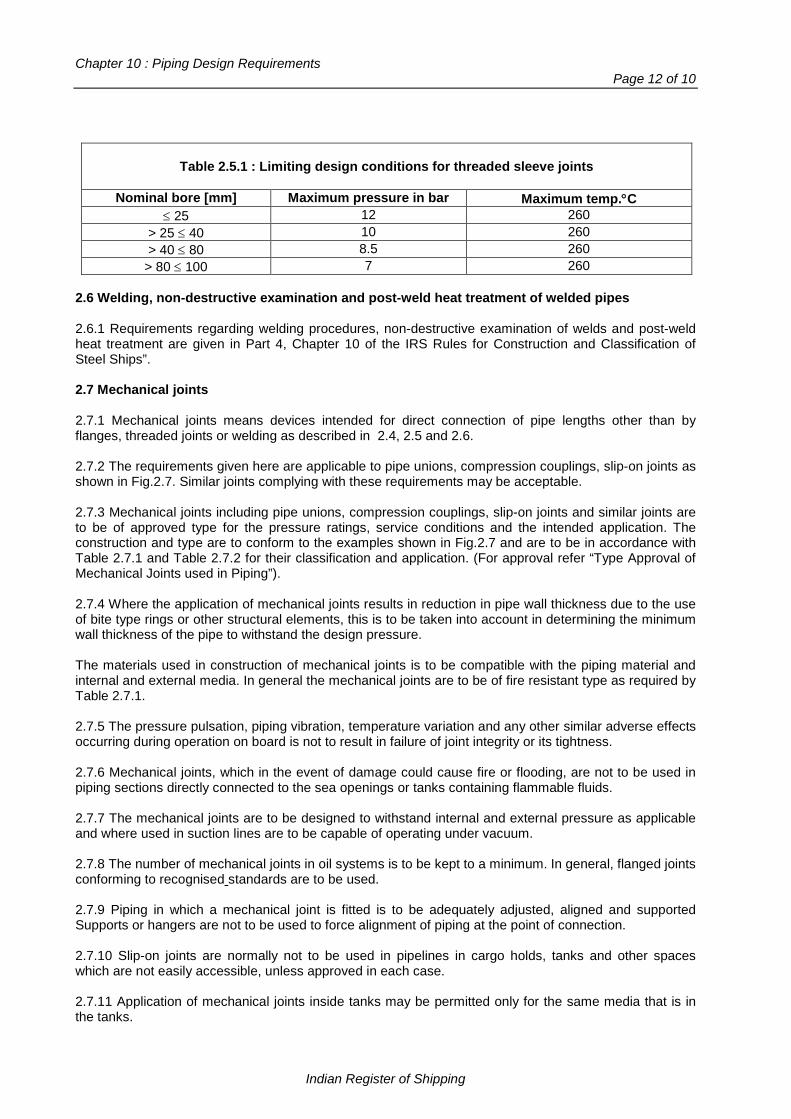
Chapter 10 : Piping Design Requirements Page 12 of 10
Table 2.5.1 : Limiting design conditions for threaded sleeve joints
Nominal bore [mm] Maximum pressure in bar Maximum temp.°C
≤ 25 12 260 > 25 ≤ 40 10 260 > 40 ≤ 80 8.5 260
> 80 ≤ 100 7 260 2.6 Welding, non-destructive examination and post-weld heat treatment of welded pipes 2.6.1 Requirements regarding welding procedures, non-destructive examination of welds and post-weld heat treatment are given in Part 4, Chapter 10 of the IRS Rules for Construction and Classification of Steel Ships”. 2.7 Mechanical joints 2.7.1 Mechanical joints means devices intended for direct connection of pipe lengths other than by flanges, threaded joints or welding as described in 2.4, 2.5 and 2.6. 2.7.2 The requirements given here are applicable to pipe unions, compression couplings, slip-on joints as shown in Fig.2.7. Similar joints complying with these requirements may be acceptable. 2.7.3 Mechanical joints including pipe unions, compression couplings, slip-on joints and similar joints are to be of approved type for the pressure ratings, service conditions and the intended application. The construction and type are to conform to the examples shown in Fig.2.7 and are to be in accordance with Table 2.7.1 and Table 2.7.2 for their classification and application. (For approval refer “Type Approval of Mechanical Joints used in Piping”). 2.7.4 Where the application of mechanical joints results in reduction in pipe wall thickness due to the use of bite type rings or other structural elements, this is to be taken into account in determining the minimum wall thickness of the pipe to withstand the design pressure. The materials used in construction of mechanical joints is to be compatible with the piping material and internal and external media. In general the mechanical joints are to be of fire resistant type as required by Table 2.7.1. 2.7.5 The pressure pulsation, piping vibration, temperature variation and any other similar adverse effects occurring during operation on board is not to result in failure of joint integrity or its tightness. 2.7.6 Mechanical joints, which in the event of damage could cause fire or flooding, are not to be used in piping sections directly connected to the sea openings or tanks containing flammable fluids. 2.7.7 The mechanical joints are to be designed to withstand internal and external pressure as applicable and where used in suction lines are to be capable of operating under vacuum. 2.7.8 The number of mechanical joints in oil systems is to be kept to a minimum. In general, flanged joints conforming to recognised standards are to be used. 2.7.9 Piping in which a mechanical joint is fitted is to be adequately adjusted, aligned and supported Supports or hangers are not to be used to force alignment of piping at the point of connection. 2.7.10 Slip-on joints are normally not to be used in pipelines in cargo holds, tanks and other spaces which are not easily accessible, unless approved in each case. 2.7.11 Application of mechanical joints inside tanks may be permitted only for the same media that is in the tanks.
Indian Register of Shipping

Rules and Regulations for the Construction and Classification of Indian Coast Guard Ships - 2015 Page 13 of 21
___________________________________________________________________________________
2.7.12 Unrestrained slip-on joints are to be used only in cases where compensation of lateral pipe deformation is necessary. Usage of these joints as the main means of pipe connection is not permitted. 2.7.13 In particular cases, sizes in excess of those mentioned in Table 2.7.2 may be accepted if in compliance with a recognised national and/or international standard. 2.7.14 Mechanical joints are to be subjected to the following tests:
.1 leakage test
.2 vacuum test
.3 vibration (fatigue) test
.4 fire endurance test
.5 burst pressure test at 4 times the design pressure (for design pressures above 200 bar, the burst pressure will be specially considered by IRS) .6 pressure pulsation test .7 assembly test .8 pull out test.
NOTE : For details of tests refer classification notes, “Type Approval of Mechanical Joints used in Piping”. 2.7.15 The installation of mechanical joints is to be in accordance with the manufacturer’s assembly instructions and using special tools and gauges as required.
Table 2.7.1 : Application of mechanical joints
Systems Kind of connections
Pipe unions Compression couplings 6)
Slip-on joints
Flammable Fluids (Flash point ≤ 60°) 1 Cargo oil lines + + +5) 2 Crude oil washing lines + + +5) 3 Vent lines + + +3)
Inert Gas 4 Water seal effluent lines + + + 5 Scrubber effluent lines + + + 6 Main lines + + +2) 5) 7 Distributions lines + + +5)
Flammable Fluids (Flash point > 60°) 8 Cargo oil lines + + +5) 9 Fuel oil lines + + +3) 2)
10 Lubricating oil lines + + +2) 3) 11 Hydraulic oil + + +2) 3) 12 Thermal oil + + +2) 3)
Sea Water 13 Bilge lines + + +1) 14 Fire main and water spray + + +3) 15 Foam system + + +3) 16 Sprinkler system + + +3) 17 Ballast system + + +1)
Sea Water (contd.) 18 Cooling water system + + +1) 19 Tank cleaning services + + + 20 Non-essential systems + + +
Fresh Water 21 Cooling water system + + +1) 22 Condensate return + + +1) 23 Non-essential system + + +
Indian Register of Shipping

Chapter 10 : Piping Design Requirements Page 14 of 10
Table 2.7.1 (Contd.)
Systems Kind of connections
Pipe unions Compression couplings 6)
Slip-on joints
Sounding / Vent Sanitary / Drains / Scuppers
24 Deck Drains (Internal) + + +4) 25 Sanitary Drains + + + 26 Scuppers and Discharge
(Overboard) + + -
27 Water tanks / Dry spaces + + + 28 Oil tanks (f.p > 60°C) + + +2) 3)
Miscellaneous 29 Starting / Control air 1) + + - 30 Service air (non-essential) + + + 31 Brine + + + 32 CO2 system 1) + + - 33 Steam + + -
Abbreviations + Application is allowed - Application is not allowed Footnotes: 1) Inside machinery spaces of category A – only approved fire resistant types. 2) Not inside machinery spaces of category A or accommodation spaces. May be accepted in other
machinery spaces provided the joints are located in easily visible and accessible positions. 3) Approved fire resistant types 4) Above free board deck only. 5) In pump rooms and open decks – only approved fire resistant types. 6) If compression couplings include any components which readily deteriorate in case of fire, they are
to be of approved fire resistant type as required for slip-on joints.
Table 2.7.2 : Application of mechanical joints depending upon the class of piping
Types of joints Classes of piping systems
Class I Class II Class III Pipe Unions
Welded and brazed type
+ (OD ≤ 60.3 mm) + (OD ≤ 60.3 mm) +
Compression Couplings Swage type + + + Bite type Flared type
+ (OD ≤ 60.3 mm) + (OD ≤ 60.3 mm)
+ (OD ≤ 60.3 mm) + (OD ≤ 60.3 mm)
+ +
Press type - - + Slip-on joints
Machine grooved type + + + Grip type - + + Slip type - + +
Indian Register of Shipping
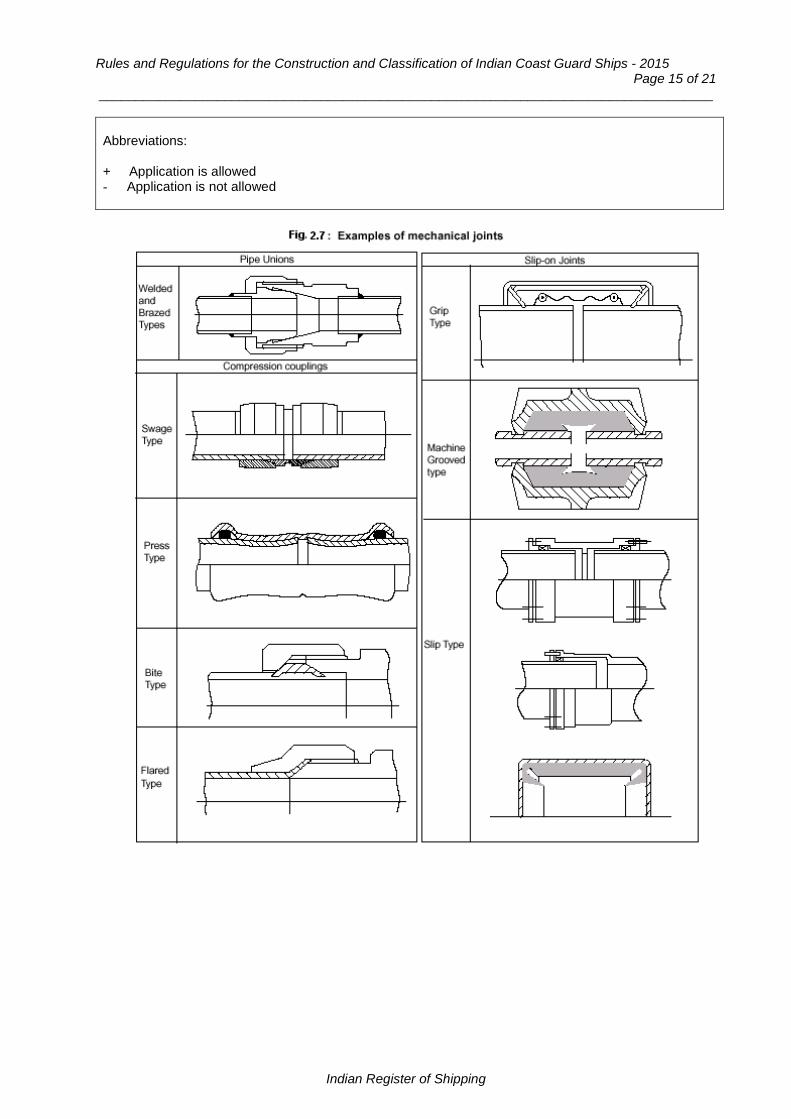
Rules and Regulations for the Construction and Classification of Indian Coast Guard Ships - 2015 Page 15 of 21
___________________________________________________________________________________
Abbreviations: + Application is allowed - Application is not allowed
Indian Register of Shipping

Chapter 10 : Piping Design Requirements Page 16 of 10
Section 3
Copper and Copper Alloy Pipes and Fittings
3.1 Materials 3.1.1 Pipes are to be seamless and branches are to be provided by cast or stamped fittings, pipe pressings or other approved fabrications. Copper pipes for class I and II are to be seamless. 3.1.2 Brazing and welding materials are to be suitable for the operating temperature and for the medium being carried. All brazing and welding are to be carried out to the satisfaction of the Surveyors. 3.1.3 In general, the maximum permissible service temperature of copper and copper alloy pipes, valves and fittings is not to exceed 200°C for copper and aluminium brass, and 300°C for copper nickel. Cast bronze valves and fittings complying with the requirements of Pt.2 Ch.8 of Rules and Regulations for Construction and Classification of Steel Ships may be accepted up to 260°C. 3.2 Minimum thickness of pipes 3.2.1 The minimum thickness of copper and copper alloy pipes and bends is to be higher of that calculated by Sec.1, Cl.1.7 and that indicated in Table 3.2.2. 3.2.2 The value of 'c' to be used in Sec.1, 1.7 is to be in accordance with Table 3.2.3. 3.3 Heat treatment 3.3.1 Pipes which have been hardened by cold bending are to be suitably heat treated on completion of fabrication and prior to being tested by hydraulic pressure. Copper pipes are to be annealed and copper alloy pipes are to be either annealed or stress relief heat treated.
Table 3.2.1 : Copper and copper alloy pipes
Pipe material Condition of supply
Specified min.
tensile strength [N/mm2]
Permissible stress [N/mm2]
Maximum design temperature °C
50 75 100 125 150 175
Copper Annealed 220 41.2 41.2 40.2 40.2 34.3 27.5
Aluminium brass Annealed 320 78.5 78.5 78.5 78.5 78.5 78.5 95/5 90/10 copper nickel-iron Annealed 270 68.6 68.6 67.7 65.7 63.7 61.8
70/30 copper nickel Annealed 360 81.4 79.4 77.5 75.5 73.5 71.6
Maximum design temperature °C
200 225 250 275 300
Copper Annealed 220 18.6 - - - -
Aluminium brass Annealed 320 24.5 - - - - 95/5 90/10 copper nickel-iron Annealed 270 58.8 55.9 52.0 48.1 44.1
70/30 copper nickel Annealed 360 69.6 67.7 65.7 63.7 61.8 Notes : 1. Intermediate values may be determined by linear interpolation. 2. For materials not included in the Table, the permissible stress shall be specially considered by IRS.
Indian Register of Shipping

Rules and Regulations for the Construction and Classification of Indian Coast Guard Ships - 2015 Page 17 of 21
___________________________________________________________________________________
Table 3.2.2 : Minimum thickness for copper and copper alloy pipes
Standard pipe sizes (outside diameter[mm])
Minimum overriding nominal thickness [mm] Copper Copper alloy
8 to 10 1.0 0.8 12 to 20 1.2 1.0
25 to 44.5 1.5 1.2 50 to 76.1 2.0 1.5 88.9 to 108 2.5 2.0 133 to 159 3.0 2.5
193.7 to 267 3.5 3.0 273 to 457.2 4.0 3.5
508 4.5 4.0
Table 3.2.3 : Corrosion allowance 'c' for copper and copper alloy pipes
Piping Material c [mm] Copper, brass and similar alloys, copper-tin alloys except those with lead contents Copper-nickel alloys (with Ni ≥ 10%)
0.8
0.5 Note: For media without corrosive action in respect of the material employed and in case of special alloys with sufficient corrosion resistance, the corrosion allowance may be reduced to zero.
Section 4
Cast Iron Pipes and Fittings
4.1 Spheroidal or nodular graphite cast iron 4.1.1 Spheroidal or nodular graphite iron castings for pipes, valves and fittings in Class II and III piping systems are to be made in a grade having a specified minimum elongation not less than 12 per cent on gauge length of 5.65√So, where So is the actual cross-sectional area of the test piece. 4.1.2 Proposals for the use of this material in Class I piping systems will be specially considered, but in no case is the material to be used in systems where the design temperature exceeds 350°C. 4.1.3 Where the elongation is less than the minimum required by 4.1.1, the material is, in general, to be subject to the same limitations as grey cast iron. 4.2 Grey cast iron 4.2.1 Grey cast iron pipes, valves and fittings will, in general, be accepted in Class III piping systems except as stated in 4.2.2. Grey cast iron valves and fittings may be accepted in the Class II steam systems, but the design pressure or temperature is not to exceed 13 bar or 220°C respectively.
Indian Register of Shipping

Chapter 10 : Piping Design Requirements Page 18 of 10
4.2.2 Grey cast iron is not to be used for the following:
a) Pipes for steam systems and fire extinguishing systems; b) Pipes, valves and fittings for boiler blow down systems and other piping systems subject to
shock or vibration; c) Ship-side valves and fittings; d) Valves fitted on collision bulkhead; e) Clean ballast lines through cargo oil tanks to forward ballast tanks; f) Bilge lines in tanks; g) Outlet valves of fuel and lubricating oil tanks with static head.
Section 5
Plastic Pipes and Fittings
5.1 General 5.1.1 Proposals to use plastics material in shipboard piping systems will be considered in relation to the properties of the materials, the operating conditions of temperature and pressure, and the intended service. Any proposed service for plastics pipes is subject to special consideration and approval by the Indian Coast Guard Authority. 5.1.2 “Guidelines for the Application of Plastic Pipes on Ships” contained in IMO Resolution A.753(18) are to be complied with.
Section 6
Flexible Hoses
6.1 General 6.1.1 Short joining lengths of flexible hoses of approved type may be used, where necessary to accommodate relative movement between various items of machinery connected to permanent piping systems. 6.1.2 For the purpose of approval for the applications in 6.2, details of the materials and construction of the hoses, and the method of attaching the end fittings, are to be submitted for consideration. 6.1.3 In general, the use of hose clips as a means of securing the ends of hoses is to be restricted to the engine cooling water system, where the hose consists of a short, straight length joining two metal pipes, between two fixed points on the engine. 6.1.4 Prototype pressure tests are to be carried out on each new type of hose, complete with end fittings, and in no case is the bursting pressure to be less than five times the maximum working pressure in service. Additionally, flexible hoses used in piping systems for flammable liquids in machinery spaces or other spaces with similar fire risks and for sea water systems where the failure of hoses could give rise to danger of flooding, are to be subjected to a fire test as given in 6.1.5. However, in sea water systems where the hoses are suitably enclosed as per 6.2.1, the fire test is not required.
Indian Register of Shipping
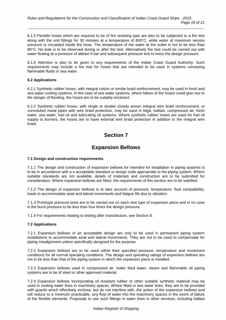
Rules and Regulations for the Construction and Classification of Indian Coast Guard Ships - 2015 Page 19 of 21
___________________________________________________________________________________
6.1.5 Flexible hoses which are required to be of fire resisting type are also to be subjected to a fire test along with the end fittings for 30 minutes at a temperature of 800°C, while water at maximum service pressure is circulated inside the hose. The temperature of the water at the outlet is not to be less than 80°C. No leak is to be observed during or after the test. Alternatively fire test could be carried out with water flowing at a pressure of atleast 5 bar and subsequent pressure test to twice the design pressure. 6.1.6 Attention is also to be given to any requirements of the Indian Coast Guard Authority. Such requirements may include a fire test for hoses that are intended to be used in systems conveying flammable fluids or sea water. 6.2 Applications 6.2.1 Synthetic rubber hoses, with integral cotton or similar braid reinforcement, may be used in fresh and sea water cooling systems. In the case of sea water systems, where failure of the hoses could give rise to the danger of flooding, the hoses are to be suitably enclosed. 6.2.2 Synthetic rubber hoses, with single or double closely woven integral wire braid reinforcement, or convoluted metal pipes with wire braid protection, may be used in bilge, ballast, compressed air, fresh water, sea water, fuel oil and lubricating oil systems. Where synthetic rubber hoses are used for fuel oil supply to burners, the hoses are to have external wire braid protection in addition to the integral wire braid.
Section 7
Expansion Bellows
7.1 Design and construction requirements 7.1.1 The design and construction of expansion bellows for intended for installation in piping systems is to be in accordance with a n acceptable standard or design code appropriate to the piping system. Where suitable standards are not available, details of materials and construction are to be submitted for consideration. Where expansion bellows are fitted, the requirements of this section are to be satisfied. 7.1.2 The design of expansion bellows is to take account of pressure, temperature, fluid compatibility, loads to accommodate axial and lateral movements and fatigue life due to vibration. 7.1.3 Prototype pressure tests are to be carried out on each new type of expansion piece and in no case is the burst pressure to be less than four times the design pressure. 7.1.4 For requirements relating to testing after manufacture, see Section 8. 7.2 Applications 7.2.1 Expansion bellows of an acceptable design are only to be used in permanent piping system installations to accommodate axial and lateral movements. They are not to be used to compensate for piping misalignment unless specifically designed for the purpose. 7.2.2 Expansion bellows are to be used within their specified pressure, temperature and movement conditions for all normal operating conditions. The design and operating ratings of expansion bellows are not to be less than that of the piping system in which the expansion piece is installed. 7.2.3 Expansion bellows used in compressed air, boiler feed water, steam and flammable oil piping systems are to be of steel or other approved material. 7.2.4 Expansion bellows incorporating oil resistant rubber or other suitable synthetic material may be used in cooling water lines in machinery spaces. Where fitted in sea water lines, they are to be provided with guards which effectively enclose, but do not interfere with, the action of the expansion bellows and will reduce to a minimum practicable, any flow of water into the machinery spaces in the event of failure of the flexible elements. Proposals to use such fittings in water lines in other services, including ballast
Indian Register of Shipping

Chapter 10 : Piping Design Requirements Page 20 of 10
lines in machinery spaces and inside water ballast tanks and bilge lines in enclosed spaces only, will be specially considered when plans of the piping systems are submitted for approval. 7.2.5 Expansion bellows are to be installed in accordance with the manufacturers instructions and are to be protected against over extension and over compression. The adjoining pipes are to be suitably aligned, supported and anchored. Where necessary, expansion bellows are to be protected against mechanical damage.
Section 8
Hydraulic Tests on Pipes and Fittings
8.1 Hydraulic tests before installation on board 8.1.1 All Class I and II pipes and their associated fittings are to be tested by hydraulic pressure to the Surveyor's satisfaction. Further, all steam, feed, compressed air and fuel oil pipes, together with their fittings, are to be similarly tested where the design pressure is greater than 3.5 bar. The test is to be carried out after completion of manufacture and before installation on board and, where applicable, before insulating and coating. 8.1.2 Where the design temperature does not exceed 300°C, the test pressure is to be 1.5 times the design pressure. 8.1.3 For steel pipes and integral fittings for use in systems where the design temperature exceeds 300°C, the test pressure is to be as follows but need not exceed twice the design pressure:
barK
KP5.1P
t
100t =
where, Pt and P are defined in Sec.1, Cl.1.5.1 K100 = allowable stress for 100°C [N/mm2] Kt = allowable stress for the design temperature [N/mm2].
8.1.4 In no case is the membrane stress to exceed 90 per cent of the yield stress at the testing temperature. 8.1.5 All valves and fittings are to be tested in accordance with recognized standards, but not less than 1.5 times the nominal pressure rating at ambient temperature. Valves, cocks and distance pieces intended to be fitted on the ship side below the load waterline are to be hydraulically tested to a pressure not less than 5 bar. 8.1.6 When, for technical reasons, it is not possible to carry out complete hydrotesting before assembly on board for all sections of piping, proposals for testing the remaining/ closing lengths of piping, particularly in respect of the closing seams, are to be submitted for approval. 8.1.7 Pressure testing of small bore pipes (less than 15 mm) may be waived at the discretion of IRS depending on the application.
Indian Register of Shipping

Rules and Regulations for the Construction and Classification of Indian Coast Guard Ships - 2015 Page 21 of 21
___________________________________________________________________________________
8.2 Testing after assembly on board 8.2.1 Heating coils in tanks and liquid or gas fuel oil piping are to be tested by hydraulic pressure, after installation on board, to 1.5 times the design pressure but in no case to less than 4 bar. 8.2.2 Where pipes specified in 8.1.1 are butt welded together during assembly on board, they are to be tested by hydraulic pressure in accordance with the requirements of 7.1 after welding. The pipe lengths may be insulated, except in way of the joints made during installation and before hydraulic test is carried out. 8.2.3 The hydraulic test required by 8.2.2 may be omitted provided non- destructive tests by ultrasonic or radiographic methods are carried out on the entire circumference of all butt welds with satisfactory results. Where ultrasonic test has been carried out, the manufacturer is to provide the Surveyor with a signed statement confirming that ultrasonic examination has been carried out by an approved operator and that there were no indications of defects which could be expected to have prejudicial effect on the service performance of the piping. 8.2.4 Where bilge pipes are accepted in way of double bottom tanks or deep tanks, the pipes after fitting are to be tested by hydraulic pressure to the same pressure as the tanks through which they pass.
End of Chapter
Indian Register of Shipping

Rules and Regulations for the Construction and Classification of Indian Coast Guard Ships - 2015 Page 1 of 17
___________________________________________________________________________________
Chapter 11
Piping Systems
Contents Section
1 Bilge, Ballast, Air Pipes and Sounding Systems
2 Machinery Piping Systems
Section 1
Bilge, Ballast, Air Pipes and Sounding Systems
1.1 Application The requirements of the sub-sections below are in general applicable to Ships of 150 GT or more. Requirements for ships of less than 150 GT are given in 1.5. 1.2 Shell Valves and Fittings (other than those on scuppers and sanitary discharges) 1.2.1 Construction 1.2.1.1 All sea inlet and overboard discharge pipes are to be fitted with valves or cocks secured direct to the shell or to fabricated water boxes attached to the shell. 1.2.1.2 Distance pieces of short rigid construction and made of approved material may be fitted between the valve and shell. The thickness of such pipes is to be equivalent to shell thickness. 1.2.1.3 The arrangements are to be such that the section of pipe immediately inboard of the shell valve may be removed without affecting the watertight integrity of the hull. 1.2.1.4 Shell valves are to be manufactured from non-heat sensitive materials and tested in accordance with the appropriate requirements of Chapter 2. Where the valves are manufactured from spheroidal or nodular graphite cast iron they are to be produced at an approved work. Grey cast iron is not acceptable. 1.2.1.5 Shell valves are to be fitted in accessible positions and are to be capable of being operated from positions which are readily accessible in case of influx of water to the compartment. 1.2.1.6 Valve hand wheels and cock handles are to be suitably retained on the spindles. Means are to be provided to indicate whether the valve or cock is open or closed. 1.2.1.7 The scantlings of valves and valve stools fitted with steam or compressed air clearing connections are to be suitable for the maximum pressure to which the valves and stools may be subjected. 1.3 Bilge Pumping and Drainage Systems 1.3.1 Drainage of compartments, other than machinery spaces 1.3.1.1 All ship are to be provided with efficient pumping plant having the suctions and means for drainage so arranged that any water within any compartment of the ship, or any watertight section of any compartment, can be pumped out through at least one suction when the ship is on an even keel and is either upright or has a list of not more than 5o. For this purpose, wing suctions will generally be
Indian Register of Shipping

Chapter 11 : Piping Systems Page 2 of 17
___________________________________________________________________________________
necessary, except in shot narrow compartments where one suction can provide effective drainage under the above conditions. 1.3.1.2 In the case of dry compartments, the suctions required by 1.3.1.1 are, except where otherwise stated, to be branch bilge suctions, i.e. suctions connected to a main bilge line. 1.3.2 Tanks and cofferdams 1.3.2.1 All tanks (including double bottom tanks), whether used for water ballast, oil fuel or liquid cargoes, are to be provided with suction pipes, led to suitable power pumps, from the after end of each tank. 1.3.2.2 In general, the drainage arrangements are to be in accordance with 1.3.1. However, where the tanks are divided by longitudinal watertight bulkheads or girders into two or more tanks, a single suction pipe, led to the after end of each tank, will normally be acceptable. 1.3.2.3 Similar drainage arrangements are to be provided for cofferdams, except that the suctions may be led to the main bilge line. 1.3.3 Fore and after peaks 1.3.3.1 Where the peaks are used as tanks, a power pump suction is to be led to each tank, except in the case of small tanks used for the carriage of domestic fresh water, where hand pumps may be used. 1.3.3.2 Where the peaks are not used as tanks, and main bilge line suctions are not fitted, drainage of both peaks may be effected by hand pump suctions, provided that the suction lift is well within the capacity of the pumps. Drainage of the after peak may be effected by means of a self-closing cock fitted in a well lighted and readily accessible position. 1.3.3.3 Pipes piercing the collision bulkhead are to be fitted with suitable valves secured to the bulkhead. The valves are to be operable from above the freeboard deck. 1.3.4 Spaces above fore peaks, after peaks and machinery spaces 1.3.4.1 Provision is to be made for the drainage of the chain locker and watertight compartments above the fore peak tank by hand or power pump suctions. 1.3.4.2 Steering gear compartments or other small enclosed spaces situated above the after peak tank are to be provided with suitable means of drainage, either by hand or power pump bilge suctions. 1.3.4.3 The compartments referred above may be drained by scuppers of not less than 38 [mm] bore, discharging to the tunnel or machinery space and fitted with self-closing cocks situated in well lighted and visible positions. 1.3.5 Maintenance of integrity of bulkheads 1.3.5.1 The integrity of the machinery space bulkheads and of tunnel plating required to be of watertight construction, is not to be impaired by the fitting of scuppers discharging to machinery space or tunnels from adjacent compartments which are situated below the bulkhead deck. 1.3.5.2 No drain valve or cock is to be fitted to the collision bulkhead. Drain valves or cocks are not to be fitted to other watertight bulkheads if alternative means of drainage are practicable. 1.3.6 Bilge drainage of machinery space 1.3.6.1 The bilge drainage arrangements in the machinery space are to comply with 1.3.1 except that the arrangements are to be such that any water which may enter this compartment can be pumped out through at least two bilge suctions when the ship is on an even keel, and is either upright or has a list of not more than 5 o. One of these suctions is to be a branch bilge suction, i.e. a suction connected to the main bilge line and the other is to be a direct bilge suction i.e. a suction led direct to an independent power pump.
Indian Register of Shipping

Rules and Regulations for the Construction and Classification of Indian Coast Guard Ships - 2015 Page 3 of 17
___________________________________________________________________________________
1.3.7 Machinery space with double bottom 1.3.7.1 Where the double bottom extends the full length of the machinery space and forms bilges at the wings, it will be necessary to provide one branch and one direct bilge suction at each side. 1.3.7.2 Where the double bottom plating extends the full length and breadth of the compartment, one branch bilge suction and one direct bilge suction are to be led to each of two bilge wells, situated one at each side. 1.3.7.3 Where there is no double bottom and the rise of floor is not less than 5o, one branch and one direct bilge suction are to be led to accessible positions as near the centre line as practicable. 1.3.8 Machinery space – Emergency bilge drainage 1.3.8.1 In addition to the bilge suctions detailed in 1.3.6 to 1.3.7, emergency bilge suction is to be provided in each main machinery space. This suction is to be led to the main cooling water pump from a suitable low level in the machinery space and is to be fitted with a screw down non return valve having the spindle so extended that the hand wheel is not less than 460 [mm] above the bottom platform. 1.3.8.2 Where two or more cooling water pumps are provided, each capable of supplying cooling water for normal power, only one pump need be fitted with an emergency bilge suction. 1.3.8.3 Where main cooling water pumps are not suitable for bilge pumping duties, the emergency bilge suction is to be led to the largest available power pump, which is not a bilge pump. 1.3.8.4 Emergency bilge suction valve name plates are to be marked ‘For emergency use only’. 1.3.9 Sizes of bilge suction pipes 1.3.9.1 The diameter, dm, of the main bilge line is to be not less than that required by the following formula, to the nearest pipe size of recognized standard, but in no case is the diameter to be less than that required for any branch bilge suction:
dm = 1.68 √{L (B + D)} + 25 [mm]
where, dm = internal diameter of main bilge line, in mm B = greatest moulded breadth of ship, in metres D = moulded depth to bulkhead deck, in metres L = Rule length of ship in metres.
1.3.9.2 The diameter db, of branch bilge suction pipes to cargo and machinery spaces is to be not less than required by the following formula, to the nearest 5 [mm], but in no case is the diameter of any suction to be less than 50 [mm]:
db = 2.15 √{C (B + D)} + 25 [mm]
where. db = internal diameter of branch bilge suction, in mm C = length of compartment, in metres B and D are as defined in 1.3.9.1
1.3.9.3 The direct bilge suctions in the machinery space are not to be of a diameter less than that required for the main bilge line. 1.3.9.4 For sizes of emergency bilge suctions, see 1.3.8.
Indian Register of Shipping

Chapter 11 : Piping Systems Page 4 of 17
___________________________________________________________________________________
1.3.10 Distribution chest branch pipes 1.3.10.1 The area of each branch pipe connecting the bilge main to a distribution chest is to be not less than the sum of the areas required by the Rules for the two largest branch bilge suction pipes connected to that chest, but need not be greater than that required for the main bilge line. 1.3.11 Pumps on bilge service and their connections 1.3.11.1 At least two power bilge pumping units are to be provided in the machinery space. One of these units may be worked from the main engines and the other is to be independently driven. 1.3.11.2 Each unit may consist of one or more pumps connected to the main bilge line, provided that their combined capacity is adequate. 1.3.11.3 A bilge ejector in combination with a high pressure sea water pump may be accepted as a substitute for an independent bilge pump as required by 1.3.11.1 1.3.11.4 Special consideration will be given to the number of pumps for small ships and in general, if there is a class notation restricting a small ship to harbour or river service a hand pump may be accepted in lieu of one of the bilge pumping units. 1.3.12 General service pumps 1.3.12.1 The bilge pumping units, or pumps, required by 1.3.11 may also be used for ballast, fire or general service duties of an intermittent nature, but they are to be immediately available for bilge duty when required. 1.3.13 Capacity of pumps 1.3.13.1 Each bilge pumping unit is to be connected to the main bilge line and is to be capable of giving a speed of water through the Rule size of main bilge pipe of not less than 122 [m/min]. 1.3.13.2 The capacity of each bilge pumping unit or bilge pump is to be not less than required by the following formula:
Q = 5.75/103 dm2
where, dm = rule internal diameter of main bilge line, mm Q = capacity, in m3/hour.
1.3.13.3 Where one bilge pumping unit is of slightly less than Rule capacity, the deficiency may be made good by an excess capacity of the other unit. In general, the deficiency is to be limited to 30 percent. 1.3.14 Self-priming pumps 1.3.14.1 All power pumps, which are essential for bilge services are to be of the self-priming type, unless an approved central priming system is provided for these pumps. Details of this system are to be submitted. 1.3.14.2 Cooling water pumps having emergency bilge suctions need not be of the self-priming type. 1.3.15 Pump connections 1.3.15.1 The connections at the bilge pumps are to be such that one unit may continue in operation when the other unit is being opened up for overhaul. 1.3.15.2 Pumps required for essential services are not to be connected to a common suction or discharge chest or pipe unless the arrangements are such that the working of any pumps so connected is unaffected by the other pumps being in operation at the same time.
Indian Register of Shipping

Rules and Regulations for the Construction and Classification of Indian Coast Guard Ships - 2015 Page 5 of 17
___________________________________________________________________________________
1.3.16 Direct bilge suctions 1.3.16.1 The direct bilge suctions in the machinery space are to be led to independent power pumps, and the arrangements are to be such that these direct suctions can be used independently of the main bilge line suctions. 1.3.17 Main bilge line suctions 1.3.17.1 Suctions from the main bilge line, i.e. branch bilge suctions, are to be arranged to draw water from any hold or machinery compartment within the ship excepting small spaces such as those mentioned in 1.3.3 and 1.3.4 where manual pump suctions are accepted and are not to be of smaller diameter than that required by the formula in 1.3.9.2 1.3.18 Prevention of communication between compartments 1.3.18.1 The arrangement of valves, cocks and their connections is to be such as to prevent the possibility of one watertight compartment being placed in communication with another, or of dry cargo spaces, machinery spaces or other dry compartments being placed in communication with the sea or with tanks. For this purpose, screw-down- non-return valves are to be provided in the following fittings:
a) Bilge valve distribution chests;
b) Bilge suction hose connections, whether fitted direct to the pump or on the main bilge line;
c) Direct bilge suctions and bilge pump connections to main bilge line. 1.3.19 Isolation of bilge system 1.3.19.1 Bilge pipes which are required for draining cargo or machinery spaces are to be entirely distinct from sea inlet pipes or from pipes which may be used for filling or emptying spaces where water or oil is carried. This does not, however, exclude a bilge ejection connection, a connecting pipe from a pump to its suction valve chest, or a deep tank suction pipe suitably connected through a change over device to a bilge, ballast or oil line. 1.3.20 Machinery space suctions – Mud boxes 1.3.20.1 Suctions for bilge drainage in machinery spaces and tunnels, other than emergency suctions, are to be led from easily accessible mud boxes fitted with straight tail pipes to the bilges and having covers secured in such a manner as to permit their being expeditiously opened or closed., Strum boxes are not to be fitted to the lower ends of these tail pipes or to the emergency bilge suctions. 1.3.21 Hold suctions – Strum boxes 1.3.21.1 The open ends of bilge suctions in holds and other compartments outside machinery spaces and tunnels are to be enclosed in strum boxes having perforations of not more than 10 [mm] diameter, whose combined areas is not less than twice that required for the suction pipe. The boxes are to be so constructed that they can be cleared without breaking any joint of the suction pipe. 1.3.22 Tail pipes 1.3.22.1 The distance between the foot of all bilge tail pipes and the bottom of the bilge well is to be adequate to allow a full flow of water and to facilitate cleaning.
Indian Register of Shipping
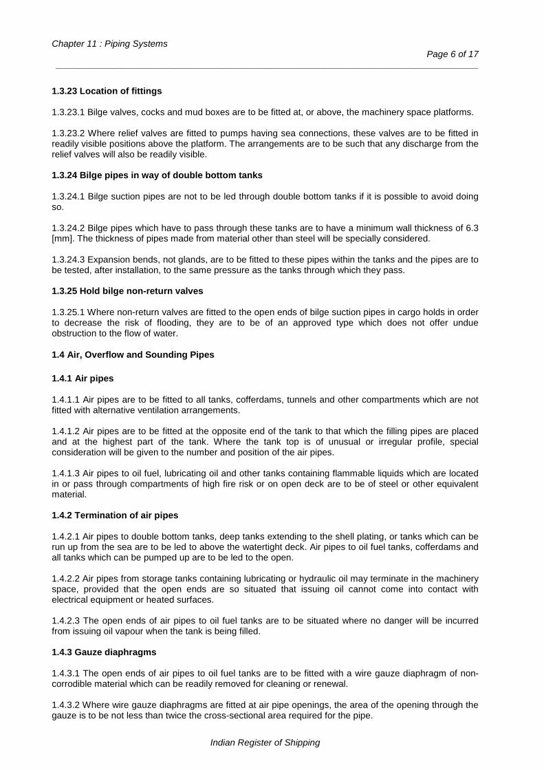
Chapter 11 : Piping Systems Page 6 of 17
___________________________________________________________________________________
1.3.23 Location of fittings 1.3.23.1 Bilge valves, cocks and mud boxes are to be fitted at, or above, the machinery space platforms. 1.3.23.2 Where relief valves are fitted to pumps having sea connections, these valves are to be fitted in readily visible positions above the platform. The arrangements are to be such that any discharge from the relief valves will also be readily visible. 1.3.24 Bilge pipes in way of double bottom tanks 1.3.24.1 Bilge suction pipes are not to be led through double bottom tanks if it is possible to avoid doing so. 1.3.24.2 Bilge pipes which have to pass through these tanks are to have a minimum wall thickness of 6.3 [mm]. The thickness of pipes made from material other than steel will be specially considered. 1.3.24.3 Expansion bends, not glands, are to be fitted to these pipes within the tanks and the pipes are to be tested, after installation, to the same pressure as the tanks through which they pass. 1.3.25 Hold bilge non-return valves 1.3.25.1 Where non-return valves are fitted to the open ends of bilge suction pipes in cargo holds in order to decrease the risk of flooding, they are to be of an approved type which does not offer undue obstruction to the flow of water.
1.4 Air, Overflow and Sounding Pipes 1.4.1 Air pipes 1.4.1.1 Air pipes are to be fitted to all tanks, cofferdams, tunnels and other compartments which are not fitted with alternative ventilation arrangements. 1.4.1.2 Air pipes are to be fitted at the opposite end of the tank to that which the filling pipes are placed and at the highest part of the tank. Where the tank top is of unusual or irregular profile, special consideration will be given to the number and position of the air pipes. 1.4.1.3 Air pipes to oil fuel, lubricating oil and other tanks containing flammable liquids which are located in or pass through compartments of high fire risk or on open deck are to be of steel or other equivalent material. 1.4.2 Termination of air pipes 1.4.2.1 Air pipes to double bottom tanks, deep tanks extending to the shell plating, or tanks which can be run up from the sea are to be led to above the watertight deck. Air pipes to oil fuel tanks, cofferdams and all tanks which can be pumped up are to be led to the open. 1.4.2.2 Air pipes from storage tanks containing lubricating or hydraulic oil may terminate in the machinery space, provided that the open ends are so situated that issuing oil cannot come into contact with electrical equipment or heated surfaces. 1.4.2.3 The open ends of air pipes to oil fuel tanks are to be situated where no danger will be incurred from issuing oil vapour when the tank is being filled. 1.4.3 Gauze diaphragms 1.4.3.1 The open ends of air pipes to oil fuel tanks are to be fitted with a wire gauze diaphragm of non-corrodible material which can be readily removed for cleaning or renewal. 1.4.3.2 Where wire gauze diaphragms are fitted at air pipe openings, the area of the opening through the gauze is to be not less than twice the cross-sectional area required for the pipe.
Indian Register of Shipping
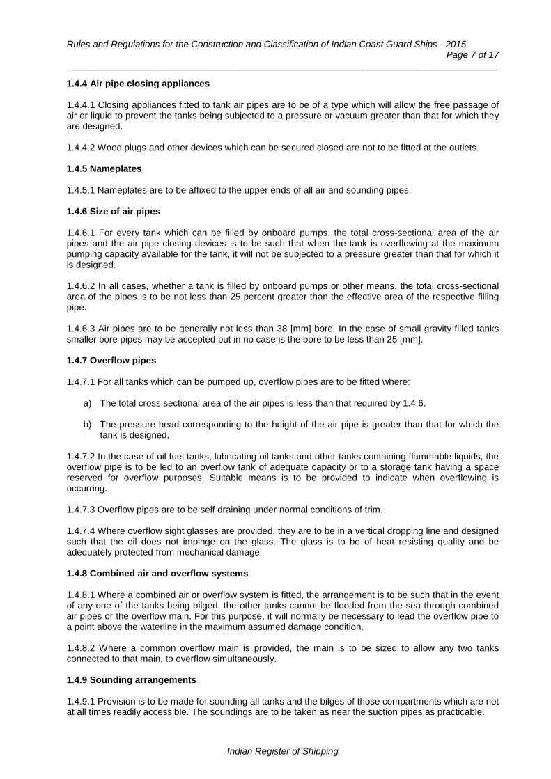
Rules and Regulations for the Construction and Classification of Indian Coast Guard Ships - 2015 Page 7 of 17
___________________________________________________________________________________
1.4.4 Air pipe closing appliances 1.4.4.1 Closing appliances fitted to tank air pipes are to be of a type which will allow the free passage of air or liquid to prevent the tanks being subjected to a pressure or vacuum greater than that for which they are designed. 1.4.4.2 Wood plugs and other devices which can be secured closed are not to be fitted at the outlets. 1.4.5 Nameplates 1.4.5.1 Nameplates are to be affixed to the upper ends of all air and sounding pipes. 1.4.6 Size of air pipes 1.4.6.1 For every tank which can be filled by onboard pumps, the total cross-sectional area of the air pipes and the air pipe closing devices is to be such that when the tank is overflowing at the maximum pumping capacity available for the tank, it will not be subjected to a pressure greater than that for which it is designed. 1.4.6.2 In all cases, whether a tank is filled by onboard pumps or other means, the total cross-sectional area of the pipes is to be not less than 25 percent greater than the effective area of the respective filling pipe. 1.4.6.3 Air pipes are to be generally not less than 38 [mm] bore. In the case of small gravity filled tanks smaller bore pipes may be accepted but in no case is the bore to be less than 25 [mm]. 1.4.7 Overflow pipes 1.4.7.1 For all tanks which can be pumped up, overflow pipes are to be fitted where:
a) The total cross sectional area of the air pipes is less than that required by 1.4.6.
b) The pressure head corresponding to the height of the air pipe is greater than that for which the tank is designed.
1.4.7.2 In the case of oil fuel tanks, lubricating oil tanks and other tanks containing flammable liquids, the overflow pipe is to be led to an overflow tank of adequate capacity or to a storage tank having a space reserved for overflow purposes. Suitable means is to be provided to indicate when overflowing is occurring. 1.4.7.3 Overflow pipes are to be self draining under normal conditions of trim. 1.4.7.4 Where overflow sight glasses are provided, they are to be in a vertical dropping line and designed such that the oil does not impinge on the glass. The glass is to be of heat resisting quality and be adequately protected from mechanical damage. 1.4.8 Combined air and overflow systems 1.4.8.1 Where a combined air or overflow system is fitted, the arrangement is to be such that in the event of any one of the tanks being bilged, the other tanks cannot be flooded from the sea through combined air pipes or the overflow main. For this purpose, it will normally be necessary to lead the overflow pipe to a point above the waterline in the maximum assumed damage condition. 1.4.8.2 Where a common overflow main is provided, the main is to be sized to allow any two tanks connected to that main, to overflow simultaneously. 1.4.9 Sounding arrangements 1.4.9.1 Provision is to be made for sounding all tanks and the bilges of those compartments which are not at all times readily accessible. The soundings are to be taken as near the suction pipes as practicable.
Indian Register of Shipping

Chapter 11 : Piping Systems Page 8 of 17
___________________________________________________________________________________
1.4.9.2 An approved level gauge or remote reading level device may be accepted in lieu of a sounding pipe. 1.4.9.3 Bilges of compartments which are not at all times readily accessible are to be provided with sounding pipes. 1.4.9.4 Where fitted, sounding pipes are to be as straight as practicable and if curved to suit the structure of the ship, the curvature is to be sufficiently easy to permit the ready passage of the sounding rod or chain. 1.4.9.5 Striking plates of adequate thickness and size are to be fitted under open ended sounding pipes. 1.4.9.6 Where slotted sounding pipes having closed ends are employed, the closing plugs are to be of substantial construction. 1.4.9.7 Sounding pipes are to be not less than 32 [mm] bore. 1.4.10 Termination of sounding pipes 1.4.10.1 Except as permitted by 1.4.11, sounding pipes are to be led to positions above the bulkhead deck which are at all times accessible and in the case of oil fuel tanks, cargo oil tanks and lubricating oil tanks, the sounding pipes are to be led to safe positions on the open deck. 1.4.11 Short sounding pipes 1.4.11.1 In machinery spaces, where it is not practicable to extend sounding pipes as mentioned in 1.4.10 short sounding pipes extending to readily accessible positions above the platform may be fitted. 1.4.12 Sounding arrangements for oil fuel, lubricating oil and other flammable liquids 1.4.12.1 Safe and efficient means of ascertaining the amount of oil in any storage tank are to be provided. 1.4.12.2 For oil fuel, lubricating oil and other flammable liquids, closed sounding devices are preferred. Design details of such devices are to be submitted and they are to be tested after fitting on board, to the satisfaction of the Surveyors. 1.4.12.3 If closed sounding devices are fitted, failure of the device or over filling of the tank is not to result in the release of tank contents. In passenger ship such means is not to require penetration below the top of the tank. 1.4.12.4 Where sounding pipes are used they are not to terminate in any space where risk of ignition or spillage from the sounding pipe might arise. In particular they are not to terminate in public spaces or crew accommodation. Additionally for oil fuel tanks they are not to terminate in machinery spaces. Terminations are to be provided with a suitable means of closure and provision to prevent spillage during refueling/refilling operations. 1.4.12.5 Where gauge glasses are used they are to be of the flat type of heat resisting quality, adequately protected from mechanical damage and fitted with self closing valves at the lower ends and at the top ends if these are connected to the tanks below the maximum liquid level. 1.5 Requirements for Ships less than 150 GT 1.5.1 General 1.5.1.1 General requirements for bilge pumping and drainage are given in the sub sections below. In general, requirements of sub-section 1.4 are to be complied with for air escape and sounding arrangements; however, 1.4.3 and 1.4.9 do not apply. 1.5.1.2 Bilge and cooling water pipe work systems are to be of steel, copper or other approved material. In wood and composite ship approved plastics material may also be used.
Indian Register of Shipping

Rules and Regulations for the Construction and Classification of Indian Coast Guard Ships - 2015 Page 9 of 17
___________________________________________________________________________________
1.5.1.3 Oil fuel and lubricating oil systems are to be of steel, copper or aluminium. Synthetic rubber hoses with single or double closely woven integral wire braid reinforcement or convoluted metal pipes with wire braid protection may be used as short joining lengths to the engine. 1.5.2 Shell valves and fittings 1.5.2.1 All sea inlet and overboard discharges are to be provided with shut off valves or cocks arranged in positions where they are readily accessible at all times. 1.5.2.2 Where valves, cocks, inlet chests, distance pieces and other sea connections are made of steel or other approved materials of low corrosion resistance they are to be suitably protected against wastage. 1.5.3 Fittings for steel and aluminium hulls 1.5.3.1 All suction and discharge valves and cocks secured direct to the plating are to be fitted with spigots passing through the plating, but spigots on the valves and cocks may be omitted if these fittings are attached to pads or distance pieces which themselves form spigots in way of the plating. 1.5.4 Fittings for wood and glass reinforced plastics hulls 1.5.4.1 The openings in the shell or planking are to have suitably reinforced areas or pads into which the attached fittings are to be spigoted. 1.5.4.2 Valves or fittings are to be secured with an external ring under the bolt heads. The ring is to be of copper nickel alloy, bronze, dezincification resistant brass or other material approved for use in sea water. 1.5.4.3 Valves or cocks upto 50 [mm] bore may be attached to spigot pieces or hull fittings having an external collar and internal nut. 1.5.4.4 Valves or cocks over 50 [mm] bore are to be flanged and attached as per 1.5.3. 1.5.5 Bilge pumping arrangements 1.5.5.1 An efficient bilge pumping system is to be fitted having suctions and means of drainage so arranged that any water which may enter any compartment could be pumped overboard. 1.5.5.2 The system is to be tested on completion of the ship to ensure that all limber holes are free and that under normal conditions of trim any bilge water can drain to an appropriate suction. 1.5.5.3 The arrangement of pumps, valves, cocks, pipes and sea connections is to be such as to prevent water entering the ship accidentally or the possibility of one watertight compartment being placed in communication with another. 1.5.5.4 Readily accessible strum boxes are to be fitted at the open ends of tail pipes. 1.5.5.5 The perforations in the strum boxes are to be not greater than 10 [mm] diameter and the combined area is to be not less than twice that required for the bilge suction pipe. 1.5.5.6 Where a collision bulkhead is fitted, the fore peak dry space is to be drained either by a branch suction to the main bilge line or by a manual pump. Alternatively, it may be drained to the adjacent compartment by means of self closing drain cock which is to be readily accessible under all conditions. 1.5.5.7 Where a bilge main is fitted, the internal diameter d of the main and the branch suction pips is to be not less than that required by the following formula:
d = L/1.2 + 25 [mm]
Indian Register of Shipping

Chapter 11 : Piping Systems Page 10 of 17
___________________________________________________________________________________
where, L = length of ship in metres.
1.5.6 Pumps on bilge service and their connections 1.5.6.1 Not less than one power pump and one manual bilge pump are to be provided. Both pumps are to be arranged to take suction from the bilge main or suction valve chest as applicable. 1.5.6.2 The power driven pumps may be used for other services such as deck washing, fire extinguishing or standby cooling water duty but not for pumping oil fuel or other flammable liquids. 1.5.6.3 The total capacity Qt of the bilge pumps is to be not less than required by the following formula:
Qt = 1.5 (d – 25) – 6.7 [m3/hour]
where, D is as defined in 1.5.10.5.7; Qt is in no case to be less than 3 [m3/hour].
1.5.6.4 A reduction in capacity of one pump may be permitted provided the deficiency is made good by an excess capacity of the other pump or by an additional pump. In no case is this deficiency to be more than 40 percent of the Rule capacity 1.5.6.5 Pumps on bilge service are to be of the self-priming type. 1.5.6.6 The bilge pumps are to be connected to a common bilge line provided with a branch connection to each compartment. 1.5.6.7 A non-return valve is to be fitted between each bilge pump and the bilge main. 1.5.6.8 Non-return valves are to be fitted in each branch bilge suction from the main bilge line. 1.5.6.9 Power pumps may be driven by the main engine, an auxiliary engine or by an electric motor. 1.5.6.10 The power pump is to be provided with a suction enabling it to pump direct from the engine space in addition to the suction from the main bilge line. This direct bilge suction is to be controlled by a screw down non-return valve or equivalent. 1.5.6.11 Manual bilge pumps are to be capable of being operated from readily accessible positions above the water line. 1.5.6.12 As an alternative to fitting a bilge main, individual submersible pumps may be fitted. In this case the arrangements are to be in accordance with the requirements, as follows :
1.5.7 Submersible Bilge Pump Arrangements 1.5.7.1 General 1.5.7.1.1 Arrangements are to be such that at least two automatic non-return devices are fitted between the overboard discharge and the watertight space being served by the pump. 1.5.7.1.2 One of these devices is to be an automatic non-return valve situated at or near the shell and the other may be a pipe work loop taken up to the highest practicable point below the watertight deck. The arrangements are to be effective in the maximum assumed damaged condition.
Indian Register of Shipping
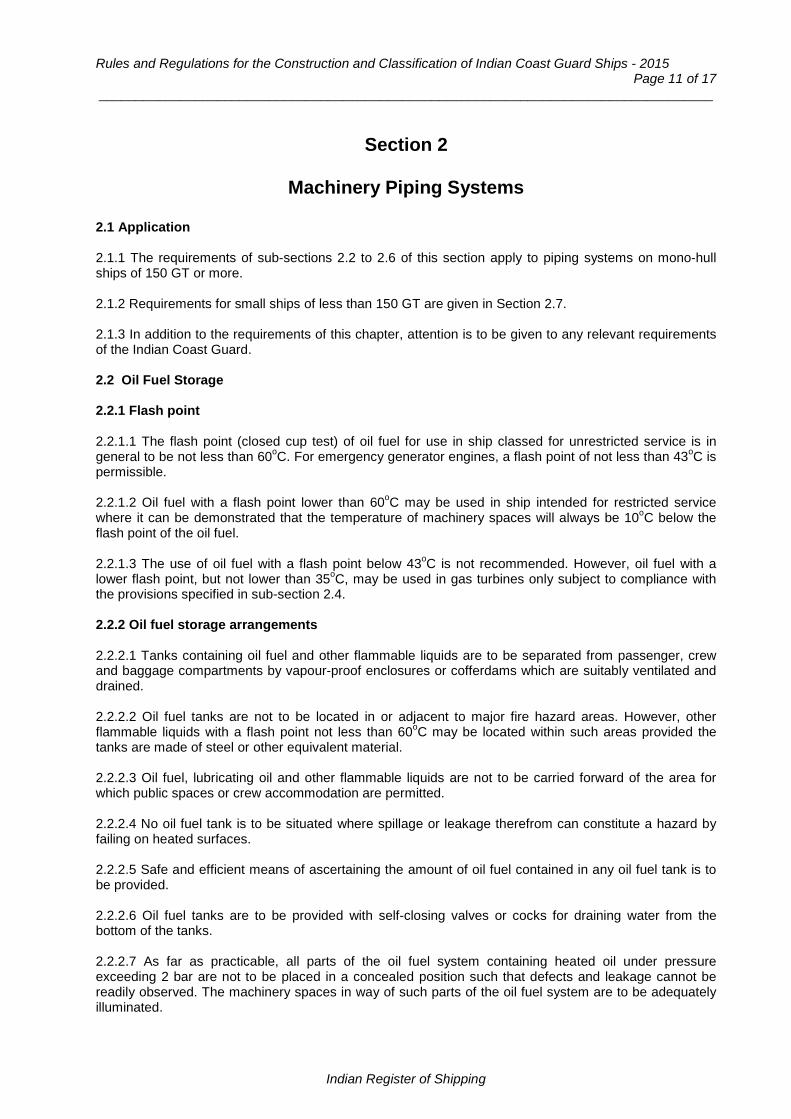
Rules and Regulations for the Construction and Classification of Indian Coast Guard Ships - 2015 Page 11 of 17
___________________________________________________________________________________
Section 2
Machinery Piping Systems
2.1 Application 2.1.1 The requirements of sub-sections 2.2 to 2.6 of this section apply to piping systems on mono-hull ships of 150 GT or more. 2.1.2 Requirements for small ships of less than 150 GT are given in Section 2.7. 2.1.3 In addition to the requirements of this chapter, attention is to be given to any relevant requirements of the Indian Coast Guard. 2.2 Oil Fuel Storage 2.2.1 Flash point 2.2.1.1 The flash point (closed cup test) of oil fuel for use in ship classed for unrestricted service is in general to be not less than 60oC. For emergency generator engines, a flash point of not less than 43oC is permissible. 2.2.1.2 Oil fuel with a flash point lower than 60oC may be used in ship intended for restricted service where it can be demonstrated that the temperature of machinery spaces will always be 10oC below the flash point of the oil fuel. 2.2.1.3 The use of oil fuel with a flash point below 43oC is not recommended. However, oil fuel with a lower flash point, but not lower than 35oC, may be used in gas turbines only subject to compliance with the provisions specified in sub-section 2.4. 2.2.2 Oil fuel storage arrangements 2.2.2.1 Tanks containing oil fuel and other flammable liquids are to be separated from passenger, crew and baggage compartments by vapour-proof enclosures or cofferdams which are suitably ventilated and drained. 2.2.2.2 Oil fuel tanks are not to be located in or adjacent to major fire hazard areas. However, other flammable liquids with a flash point not less than 60oC may be located within such areas provided the tanks are made of steel or other equivalent material. 2.2.2.3 Oil fuel, lubricating oil and other flammable liquids are not to be carried forward of the area for which public spaces or crew accommodation are permitted. 2.2.2.4 No oil fuel tank is to be situated where spillage or leakage therefrom can constitute a hazard by failing on heated surfaces. 2.2.2.5 Safe and efficient means of ascertaining the amount of oil fuel contained in any oil fuel tank is to be provided. 2.2.2.6 Oil fuel tanks are to be provided with self-closing valves or cocks for draining water from the bottom of the tanks. 2.2.2.7 As far as practicable, all parts of the oil fuel system containing heated oil under pressure exceeding 2 bar are not to be placed in a concealed position such that defects and leakage cannot be readily observed. The machinery spaces in way of such parts of the oil fuel system are to be adequately illuminated.
Indian Register of Shipping

Chapter 11 : Piping Systems Page 12 of 17
___________________________________________________________________________________
2.2.2.8 Oil fuel tanks are normally to be located outside machinery spaces and other areas of major fire hazard. 2.2.2.9 Where structural tanks are located adjacent to machinery spaces they are to be arranged such that the area of the tank common with the machinery space is kept to a minimum. In ship constructed of aluminium or other heat sensitive material the tanks are to be suitably protected against the effect of fire in the machinery space. 2.2.2.10 Where free standing tanks are fitted in machinery spaces they are to be of steel or equivalent material and positioned in an oil tight drip tray of ample size having suitable drainage arrangements to a spill oil tank. 2.2.3 Unattended machinery 2.2.3.1 Where machinery is fitted with automatic or remote controls so that under normal operating conditions it does not require any manual intervention by the operators, the requirements of 2.2.3.2 to 2.2.3.5 apply. 2.2.3.2 Where daily service tanks are filled automatically or by remote control, means are to be provided to prevent overflow spillages. 2.2.3.3 Other equipment which treats flammable liquid automatically, such as oil fuel purifiers, are to have arrangements to prevent spillage of the liquid through overflow or malfunction of seals. 2.2.3.4 Alarms are to be provided for purifier broken water seal and high oil inlet temperature. 2.2.3..5 Where daily service oil fuel tanks of settling tanks are fitted with heating arrangements, a high temperature alarm is to be provided if the flash point of the oil can be exceeded. 2.3 Oil Fuel Systems 2.3.1 Oil fuel supply to main and auxiliary engines 2.3.1.1 Two or more filters are to be fitted in the oil fuel supply lines to the main and auxiliary engines, and the arrangements are to be such that any filter can be cleaned without interrupting the supply of filtered oil fuel to the engines. 2.3.2 Booster pumps 2.3.2.1 Where an oil fuel booster pump is fitted, which is essential to the operation of the main engine, a standby pump is to be provided. 2.3.2.2 The standby pump is to be connected ready for immediate use, but where two or more main engines are fitted, each with its own pump, a complete spare pump may be accepted provided that it is readily accessible and can easily be installed. 2.3.3 Fuel valve cooling pumps 2.3.3.1 Where pumps are provided for fuel valve cooling, the arrangements are to be in accordance with 2.3.2.1 and 2.3.2.2. 2.3.4 Transfer pumps 2.3.4.1 Where a power driven pump is necessary for transferring oil fuel, a standby pump is to be provided and connected ready for use. The standby pump may be a manual pump. Alternatively, emergency connections may be made to another suitable power driven pump.
Indian Register of Shipping

Rules and Regulations for the Construction and Classification of Indian Coast Guard Ships - 2015 Page 13 of 17
___________________________________________________________________________________
2.3.5 Control of pumps 2.3.5.1 All independently driven oil fuel transfer and pressure pumps are to be capable of being stopped locally and from a position outside of the space in which they are located. The remote stop position is always to be accessible in the event of fire occurring in the space in which these pumps are located. 2.3.6 Relief valves on pumps 2.3.6.1 All pumps which are capable of developing a pressure exceeding the design pressure of the system are to be provided with relief valves. Each relief valve is to be in close circuit, i.e. arranged to discharge back to the suction side of the pump and to effectively limit the pump discharge pressure to the design pressure of the system. 2.3.7 Pump connections 2.3.7.1 Valves or cocks are to be interposed between the pumps and the suction and discharge pipes, in order that any pump may be shut off for opening up and overhauling. 2.3.8 Low pressure pipes 2.3.8.1 Transfer, suction and other low pressure pipes and all pipes passing through oil storage tanks are to be suitable for a working pressure of not less than 7 bar. 2.3.9 Valves on deep tanks and their control arrangements 2.3.9.1 Every oil fuel suction pipe from a storage, settling and daily service tank situated above the double bottom and every oil fuel leveling pipe within the machinery space is to be fitted with a valve or cock secured to the tank. 2.3.9.2 In machinery spaces such valves and cocks are to be capable of being closed locally and from positions outside these spaces which will always be accessible in the event of fire occurring in these spaces. Instructions for closing the valves or cocks are to be indicated at the valves and cocks and at the remote control positions. 2.3.9.3 In the case of tanks of less than 0.5 [m3], consideration will be given to the omission of remote controls. 2.3.9.4 Every oil fuel suction pipe which is led into the machinery spaces, from a deep tank outside these spaces is to be fitted in the machinery space with a valve controlled as in 2.3.9.2 except where the valve on the tank is already capable of being closed from an accessible position above the bulkhead deck. 2.3.9.5 Where the filling pipes to deep oil tanks are not connected to the tanks near the top, they are to be provided with non-return valves at the tanks or with valves or cocks fitted and controlled as in 2.3.9.2. 2.3.10 Filling arrangements 2.3.10.1 Filling stations are to be isolated from other spaces and are to be efficiently drained and ventilated. 2.3.10.2 Provision is to be made against over pressure in the filling pipelines. Any relief valve fitted for this purpose is to discharge to an overflow tank or other safe position. 2.4 Low Flash Point Fuels 2.4.1 General 2.4.1.1 For ship having oil fuel with a flash point below 43oC the arrangements for the storage, distribution and utilisation of the oil fuel are to be such that the safety of the ship and persons on board is preserved, having regard to fire and explosion hazards. The arrangements are to comply with sub sections 2.2 and 2.3 and 2.4.1.3 to 2.4.1.6.
Indian Register of Shipping

Chapter 11 : Piping Systems Page 14 of 17
___________________________________________________________________________________
2.4.1.2 Tanks for the storage of such oil fuel are to be located outside any machinery space and at a distance of not less than 760 [mm] inboard from the shell and bottom plating, and from decks and bulkheads. 2.4.1.3 The spaces in which oil fuel tanks are located are to be mechanically ventilated using exhaust fans providing not less than six air changes per hour. The fans are to be such as to avoid the possibility of ignition of flammable gas air mixtures. Suitable wire mesh guards are to be fitted over inlet and outlet ventilation openings. The outlets for such exhausts are to discharge to a safe position. 2.4.1.4 A fixed vapour detection system is to be installed in each space through which oil fuel lines pass, with alarms provided at a continuously manned control station. 2.4.1.5 Safe and efficient means of ascertaining the amount of oil fuel contained in any tank is to be provided. Gauge glasses are not to be used. Other means of ascertaining the amount of oil fuel contained in any tank may be permitted if such means do not require penetration below the top of the tank, and providing their failure or overfilling of the tanks will not permit the release of oil fuel. 2.4.1.6 Vessel to shore oil fuel connections are to be of closed type and suitably grounded during bunkering operations. 2.4.1.7 Provision to be made to prevent overpressure in oil tank or oil fuel system, including filling pipes. Relief valves and air or overflow pipes to terminate with flame arrestors. 2.5 Lubricating / Hydraulic Oil Systems 2.5.1 Lubricating oil arrangements 2.5.1.1 The arrangements for the storage, distribution and utilisation of oil used in pressure lubrication systems in machinery spaces and whenever practicable in auxiliary machinery spaces are to comply with the provisions of same as fuel storage. 2.5.1.2 The use of aluminium in lubricating oil sump tanks for engines or in lubricating oil filter housing fitted integral with the engines is accepted. 2.5.2 Arrangements for other flammable oils 2.5.2.1 The arrangements for storage, distribution and utilisation of other flammable oils employed under pressure in power transmission systems, control and activating systems and heating systems in locations where means of ignition are present are to comply with the provisions of fuel oil storage. 2.5.3 Lubricating/hydraulic oil standby arrangements 2.5.3.1 Where lubricating oil for the main engine(s) is circulated under pressure, a standby lubricating oil pump is to be provided where the following conditions apply:
a) The lubricating oil pump is independently driven and the total output of the main engine(s) exceeds 370 [kW].
b) One main engine with its own pump is fitted and the output of the engine exceeds 370 [kW].
c) More than one engine each with its own lubricating oil pump is fitted and the output of each
engine exceeds 370 [kW]. 2.5.3.2 The standby pump is to be of sufficient capacity to maintain the supply of oil for normal conditions with any one pump out of action. The pump is to be fitted and connected ready for immediate use, except that where the conditions referred to in 2.5.3.1(c) apply, a complete spare pump may be accepted. In all cases, satisfactory lubrication of the engines is to be ensured while starting and manoeuvring.
Indian Register of Shipping

Rules and Regulations for the Construction and Classification of Indian Coast Guard Ships - 2015 Page 15 of 17
___________________________________________________________________________________
2.5.3.3 Similar provisions to those of 2.5.3.1 and 2.5.3.2 are to be made where separate lubricating/hydraulic oil systems are employed for piston cooling, reduction gears, oil operated couplings controllable pitch propellers and steering systems etc. unless approved alternative arrangements are provided. 2.5.3.4 Independently driven pumps of rotary type are to be fitted with a non-return valve on the discharge side of the pump. 2.6 Engine Cooling Water Systems 2.6.1 General 2.6.1.1 The cooling arrangements provided are to be adequate to maintain all lubricating and hydraulic fluid temperatures within the manufacturer’s recommended limits. 2.6.2 Main supply 2.6.2.1 Provision is to be made for an adequate supply of cooling water to the main propelling machinery and essential auxiliary engines, also to the lubricating oil and fresh water coolers and air coolers for electric propelling machinery, where these coolers are fitted. The cooling water pump(s) may be worked from the engines or be driven independently. 2.6.3 Standby supply 2.6.3.1 Provisions is also to be made for a separate supply of cooling water from a suitable independent pump of adequate capacity. 2.6.3.2 The following arrangements are acceptable depending on the purpose for which the cooling water is intended:
a) Where only one main engine is fitted, the standby pump is to be connected ready for immediate use.
b) Where more than one main engine is fitted, each with its own pump, a complete spare pump of each type may be accepted.
c) Where fresh water cooling is employed for main and/or auxiliary engines, a standby fresh water
pump need not be fitted if there are suitable emergency connections from a salt water system.
d) Where each auxiliary engine is fitted with a cooling water pump, standby means of cooling need not be provided. Where, however, a group of auxiliary engine is supplied with cooling water from a common system, a standby cooling water pump is to be provided for this system. This pump is to be connected ready for immediate use and may be a suitable general service pump.
2.6.4 Selection of standby pumps 2.6.4.1 When selecting a pump for standby purposes, consideration is to be given to the maximum pressure which it can develop if the overboard discharge valve is partly or fully closed. Where necessary, water boxes etc. are to be protected against inadvertent over pressure by an approved device. 2.6.5 Relief valves on main cooling water pumps 2.6.5.1 Where cooling water pumps can develop a pressure head greater than the design pressure of the system, they are to be provided with relief valves on the pump discharge to effectively limit the pump discharge pressure to the design pressure of the system. 2.6.6 Sea inlets 2.6.6.1 Not less than two sea inlets are to be provided for the pumps supplying the sea water cooling system, one for the main pump and one for the standby pump. Alternatively, the sea inlets may be connected to a suction line available to main and standby pumps.
Indian Register of Shipping

Chapter 11 : Piping Systems Page 16 of 17
___________________________________________________________________________________
2.6.6.2 Where standby pumps are not connected ready for immediate use the main pump is to be connected to both sea inlets. 2.6.6.3 The auxiliary cooling water sea inlets are to be located one on each side of the ship. 2.6.7 Strainers 2.6.7.1 Where sea water is used for the direct cooling of the main engines and essential auxiliary engines, the cooling water suction pipes are to be provided with strainers which can be cleaned without interruption to the cooling water supply. 2.7 Requirements for Ships of less than 150 GT 2.7.1 General 2.7.1.1 The requirements for these sub-sections replace sub-sections 2.2 to 2.6 of this section for ships of less than 150 GT. 2.7.2 Oil fuel system 2.7.2.1 Where a power driven oil fuel transfer pump is fitted, it is to be capable of being stopped from a position outside the space which will always be accessible in the event of fire occurring in the compartment in which the pump is situated, as well as from the compartment itself. 2.7.2.2 Where a power driven pump is necessary for transferring oil fuel, a standby pump is to be provided and connected ready for use. 2.7.3 Separate oil fuel tanks 2.7.3.1 Except for very small tanks, separate oil fuel tanks are to be not less than 3 [mm] in thicknesses. The seams are to be welded or brazed. Steel tanks are to be protected from corrosion. 2.7.3.2 Before installation, all tanks are to be tested by a head of water equal to the maximum to which the tanks may be subjected, but not less than 3.5 [m] above the crown of the tank. 2.7.3.3 Separate oil fuel tanks are to be securely fixed in position and located as remote as practicable from exhaust manifolds and exhaust pipes or other hot surfaces and not above any electrical apparatus. Where this cannot be avoided, a drip tray is to be fitted under the tank and extended sufficiently to catch any drips from fittings attached to the tank. 2.7.3.4 Oil fuel tanks are not to be fitted above or adjacent to oil fired heaters, cooking stoves, equipment using naked flames or electrical equipment unless this is suitably constructed or enclosed. 2.7.4 Oil fuel filling, air and sounding arrangements 2.7.4.1 The filling pipe is to be of metallic construction and is to be a permanent fixture led from the deck and secured to the tank by an approved connection. A screwed cap and name plate inscribed “Oil Fuel” is to be provided at the filling point. 2.7.4.2 Flexible hoses are not permitted as filling pipes. In wood or composite ships, short lengths may be employed at the deck connection to accommodate any movement between the tank and the deck fitting. 2.7.5 Oil fuel supply 2.7.5.1 Provision is to be made for efficient filtration of the oil fuel supply to the engine.
Indian Register of Shipping

Rules and Regulations for the Construction and Classification of Indian Coast Guard Ships - 2015 Page 17 of 17
___________________________________________________________________________________
2.7.6 Oil fuel valves and cocks 2.7.6.1 Outlet valves or cocks are to be fitted to all deep tanks. The valves are to be fitted directly to the tank plating and are to be capable of being closed locally and from positions which will always be readily accessible in the event of fire. 2.7.6.2 Valve covers are to be so constructed that they will not become slack when the valves are operated. 2.7.6.3 Heat sensitive materials are not to be used in the construction of valves and cocks. 2.7.6.4 Where drain cocks or valves are fitted to oil fuel tanks they are to be of the self-closing type and suitable provision is to be made for collecting the oil discharge. 2.7.7 Flexible hoses for oil fuel systems 2.7.7.1 Where necessary, flexible pipes of approved type may be used as short joining lengths to the engine. 2.7.8 Pipe joints for oil fuel systems 2.7.8.1 Where flanged joints are used the jointing material is to be impervious to oil. Cone type joints and approved types of compression fittings may be permitted for pipes having a bore not exceeding 40 [mm]. 2.7.8.2 Soft solder is not to be used for attaching pipe fittings. 2.7.9 Engine cooling system 2.7.9.1 Where sea water is used for the direct cooling of the engine, an efficient strainer which can be cleared from inside the ship is to be fitted between the sea inlet valve and the pump. 2.7.9.2 Means are to be provided for cleaning the strainer without interruption to the cooling water supply, where necessary. 2.7.9.3 Means are to be provided for indicating the temperature of the engine cooling media. 3.7.9.4 Alarms for the engine cooling water system are to be provided. 2.7.10 Lubricating oil system 2.7.10.1 Where the lubricating oil for main propelling engines is circulated under pressure, provision is to be made for the efficient filtration of the oil. 2.7.10.2 Where necessary, flexible pipes of approved type may be used as short joining lengths to the engine. 2.7.10.3 In general, joints are to be of the flanged type with jointing materials which are impervious to oil. Cone type joints and approved types of compression fittings may be permitted for pipes having a bore not exceeding 40 [mm]. 2.7.10.4 Soft solder is not to be used for attaching pipe fittings. 2.7.10.5 Means are to be provided for indicating the lubricating oil pressure. 2.7.10.6 Alarms for the lubricating oil systems are to be provided.
End of Chapter
Indian Register of Shipping

Rules and Regulations for the Construction and Classification of Indian Coast Guard Ships - 2015
Page 1 of 60
Chapter 12
Main and Auxiliary Machinery
Contents Section
1 General Requirements for Machinery
2 Propulsion Shafting Systems
3 Prime Mover and Gearing
4 Propeller, Thruster, Water Jet System
5 Pressure Vessels
Section 1
General Requirements for Machinery
1.1 Application 1.1.1 The sections 2 to 5 apply to the design, construction, installation and testing of main propulsion machinery systems; essential auxiliary machinery systems having powers in excess of 100 [kW]; together with their associated equipment, pressure plant, piping systems, control engineering and electrical engineering systems for various ship types. 1.1.2 Requirements for ships with 150 GT or greater and with less than 150 GT are considered separately and are indicated specifically in each sub–section, as applicable. 1.1.3 These Rules are applicable for machinery systems burning distillate fuels which do not require to be heated. 1.2 General 1.2.1 The units and formulae used in the rules are in SI units. 1.2.2 Sufficient astern power is to be provided to maintain control of the ship in all normal circumstances. 1.2.3 The main propulsion machinery will be approved for the maximum continuous power and associated shaft speed, required to achieve the maximum ship velocity at the certified maximum operational weight in smooth water. 1.2.4 Main propulsion machinery will be considered for operation at a higher power rating than the classification rating for short time intervals (referred to as short term high power operation) in conjunction with the intended operation service profile.
Indian Register of Shipping

Chapter 12 : Main and Auxiliary Machinery
Page 2 of 60 __________________________________________________________________________________
1.3 Fuel flash point 1.3.1 The flash point (closed cup test) of oil fuel is in general to be not less than 60oC. For emergency generator engines a flash point of not less than 43oC is permissible. 1.3.2 Oil fuel with a flash point lower than 60oC may be used where it can be shown that the temperature of the oil fuel will always be not more than 10oC below its flash point. 1.3.3 The use of fuel with a flash point below 43oC is not recommended. However, fuel with a lower flash point, but not lower than 35oC, may be used in gas turbines only, subject to compliance with the provisions in Chapter 9, paragraph 3.7 1.4 Exhaust 1.4.1 All engines exhaust systems to be adequate to ensure the correct functioning of the machinery and the safe operation of the ship is not put at risk. 1.4.2 Where the surface temperature of the exhaust pipes and silencer may exceed 220oC, they are to be water cooled or efficiently lagged to minimise the risk of fire and to prevent damage by heat. Where lagging covering the exhaust piping system including flanges is oil-absorbing or may permit penetration of oil, the lagging is to be encased in sheet metal or equivalent. In locations where the Surveyor is satisfied that oil impingement could not occur, the lagging need not be encased. 1.5 Bearings 1.5.1 Roller element bearings are to have an L10h design life of at least 30,000 hours, based upon the design operating conditions, including short term high power operation. An L10h design life of less than 30,000 hours would be accepted provided it is proposed in conjunction with the manufacturer’s design/maintenance manual. Note : L10h is the basic rating life in hours which 90% of a sufficiently large group of apparently identical bearings is expected to attain. 1.6 Vibration of shaft systems 1.6.1 The shipbuilders are to ensure that the systems are free from excessive vibrations, excessive bearing reactions and excessive bending moments under all design operating conditions. 1.6.2 Where changes are subsequently made to a dynamic system which has been approved by IRS e.g. machining a shaft, fitting a propeller of a different design to the working propeller or fitting a different flexible coupling, full details of the changes are to be advised. Revised calculations may be required to be submitted. 1.6.3 Where there is experience of previous similar systems which have been approved, full details of these installations may be submitted for consideration in lieu of calculations. 1.7 Alternative system of survey 1.7.1 Where items of machinery are manufactured as individual or series produced units, IRS will give consideration to the adoption of a survey procedure based upon an approved quality assurance system to ISO 9001 (or equivalent) utilizing regular and systematic audits of the approved manufacturing and quality control processes and procedures as an alternative to the direct survey of individual components.
Indian Register of Shipping
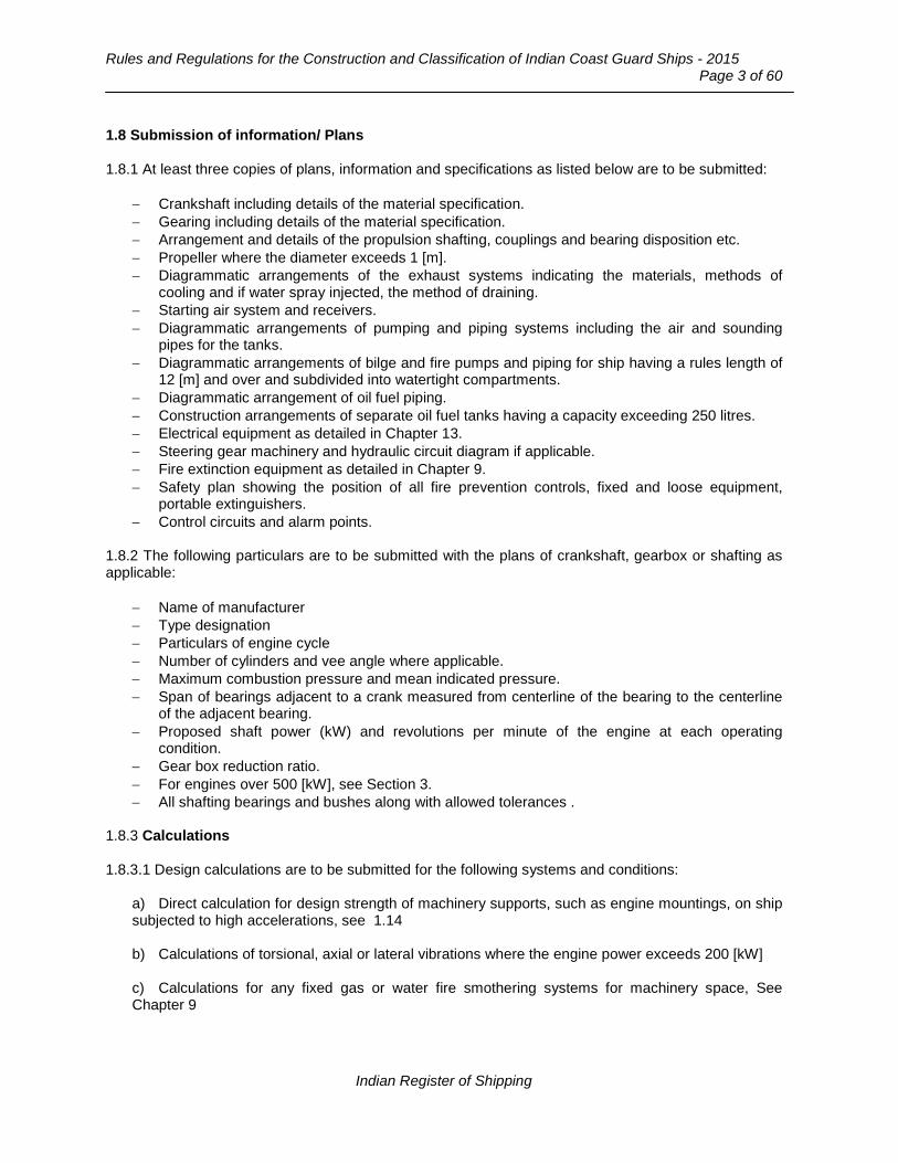
Rules and Regulations for the Construction and Classification of Indian Coast Guard Ships - 2015
Page 3 of 60
1.8 Submission of information/ Plans 1.8.1 At least three copies of plans, information and specifications as listed below are to be submitted:
− Crankshaft including details of the material specification. − Gearing including details of the material specification. − Arrangement and details of the propulsion shafting, couplings and bearing disposition etc. − Propeller where the diameter exceeds 1 [m]. − Diagrammatic arrangements of the exhaust systems indicating the materials, methods of
cooling and if water spray injected, the method of draining. − Starting air system and receivers. − Diagrammatic arrangements of pumping and piping systems including the air and sounding
pipes for the tanks. − Diagrammatic arrangements of bilge and fire pumps and piping for ship having a rules length of
12 [m] and over and subdivided into watertight compartments. − Diagrammatic arrangement of oil fuel piping. − Construction arrangements of separate oil fuel tanks having a capacity exceeding 250 litres. − Electrical equipment as detailed in Chapter 13. − Steering gear machinery and hydraulic circuit diagram if applicable. − Fire extinction equipment as detailed in Chapter 9. − Safety plan showing the position of all fire prevention controls, fixed and loose equipment,
portable extinguishers. − Control circuits and alarm points.
1.8.2 The following particulars are to be submitted with the plans of crankshaft, gearbox or shafting as applicable:
− Name of manufacturer − Type designation − Particulars of engine cycle − Number of cylinders and vee angle where applicable. − Maximum combustion pressure and mean indicated pressure. − Span of bearings adjacent to a crank measured from centerline of the bearing to the centerline
of the adjacent bearing. − Proposed shaft power (kW) and revolutions per minute of the engine at each operating
condition. − Gear box reduction ratio. − For engines over 500 [kW], see Section 3. − All shafting bearings and bushes along with allowed tolerances .
1.8.3 Calculations 1.8.3.1 Design calculations are to be submitted for the following systems and conditions:
a) Direct calculation for design strength of machinery supports, such as engine mountings, on ship subjected to high accelerations, see 1.14 b) Calculations of torsional, axial or lateral vibrations where the engine power exceeds 200 [kW] c) Calculations for any fixed gas or water fire smothering systems for machinery space, See Chapter 9
Indian Register of Shipping

Chapter 12 : Main and Auxiliary Machinery
Page 4 of 60 __________________________________________________________________________________
1.8.4 Plans are to indicate clearly the scantlings and materials of construction. Any design alteration to the plan is to be resubmitted for approval, indicating clearly the alteration. 1.8.5 Plans showing the arrangement of resiliently mounted machinery are to indicate the number, position, type and design of mounts. 1.8.7 The plans of arrangement of resin chocks for machinery requiring accurate alignment are to be submitted. 1.9 Certification of materials 1.9.1 The requirements of Part 2 of the ‘Rules and Regulations for the Construction and Classification of Steel Ships’, apply to all types of ships. Details of all materials included and not included in Part 2 are to be forwarded as soon as possible (preferably at the design concept stage) and before commencement of manufacture. 1.9.2 Where no provision is made in these Rules, materials may be accepted provided that they comply with an approved specification and such tests as may be considered necessary by the Surveyor. 1.9.3 The requirements for materials for machinery components are indicated in the relevant Part or Chapter of the Rules. 1.9.4 Where machinery system components or equipment have been approved under IRS’s Type Approval System or Machinery Design Appraisal for the proposed design conditions or intended service, full details of the components should be advised to enable the validity of the approval to be checked. In cases where valid approvals are confirmed, plans are not required to be submitted for approval for individual ships. 1.10 Specifications 1.10.1 Relevant data covering the following topics is to be submitted. 1.10.2 Service Profile: The machinery power / speed operational envelope indicating all the intended operational points applicable to the class notation and any short term high power operation. 1.10.3 Classification Rating : The following operational parameters, using the design conditions for the intended Class Notation:
− Total barometric pressure, bar. − Temperature of engine room or suction air, oC. − The relative humidity, percent. − Temperature of sea water, or charge air coolant inlet, oC.
For unrestricted service the operational parameters ambient reference conditions are to be taken as:
− Total barometric pressure, 1000 [mb]. − Temperature of engine room or suction air, 45oC. − Relative humidity, 60 percent. − Temperature of sea water or charge air coolant inlet, 32oC.
1.10.4 Short term high power operation. Where the propulsion machinery is being considered for short term high power operation full details of the power, speed and time intervals together with fatigue endurance calculations, and documentary evidence indicating the suitability of the component design
Indian Register of Shipping

Rules and Regulations for the Construction and Classification of Indian Coast Guard Ships - 2015
Page 5 of 60
under these conditions and for the intended class notation are required. The following are to be considered prime mover, gearbox, flexible coupling, vibration dampers, shafting and propeller.
a) The accrued number of load cycles and the percentage overload are to be those recommended by the designers.
b) Excessive overload may require the interval between surveys to be reduced. c) Machinery is to be maintained in accordance with manufacturer's requirements.
1.10.5 Damper and flexible coupling characteristics. Documentary evidence that the characteristics have been verified. 1.10.6 Machinery fastening
a) Documentary evidence and calculations indicating that machinery is securely mounted for the accelerations to be expected during service.
b) Calculations that mountings of large masses such as main engines, auxiliary engines, lift fans
and electrical equipment can withstand the design collision acceleration according to 1.15.1 without fracturing.
c) Natural frequency calculation of resilient mounted machinery. d) For non-metallic machinery chocks.
i) Resin type. ii) The effective area and minimum thickness of the chocks. iii) The total deadweight loading of machinery. iv) The thrust load, where applicable, that will be applied to the chocked item. v) The loading to be applied to the holding-down bolts. vi) The material of the holding-down bolts. vii) The number, thread size and waisted shank diameter (where applicable) of the holding-
down bolts.
1.10.7 Fatigue strength analysis. Where undertaken as an alternative to the requirements of the individual chapters, fatigue strength analysis of components indicating a factor of safety of 1.5 at the design loads based on a suitable fatigue failure criteria. The effects of stress concentrations, material properties and operating environment are to be taken into account. 1.11 Certification of materials of construction 1.11.1 Materials used in the construction are to be in accordance with or shown to be equivalent, to Part 2 of the ‘Rules and Regulations for the Construction and Classification of Steel Ships’. 1.12 Operating control Machinery control 1.12.1 The design and arrangement is to be such that the machinery can be started and controlled on board, without external aid, so that the operating conditions for which the ship is classed, can be maintained.
Indian Register of Shipping
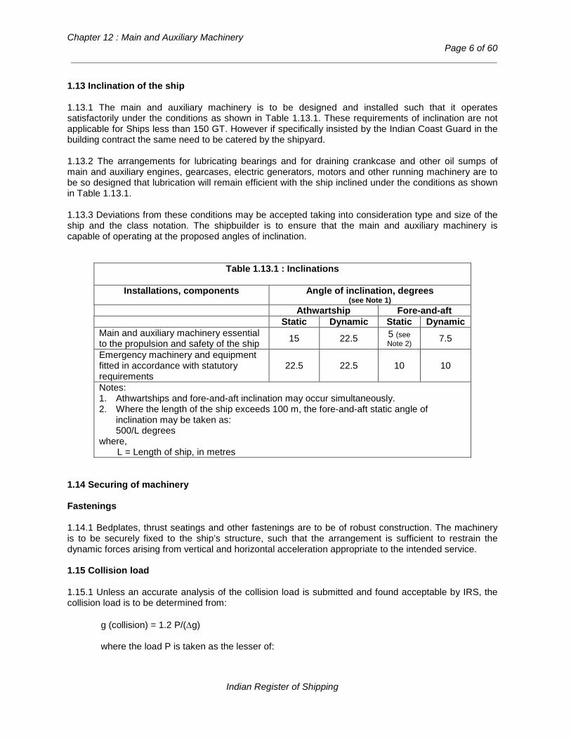
Chapter 12 : Main and Auxiliary Machinery
Page 6 of 60 __________________________________________________________________________________
1.13 Inclination of the ship 1.13.1 The main and auxiliary machinery is to be designed and installed such that it operates satisfactorily under the conditions as shown in Table 1.13.1. These requirements of inclination are not applicable for Ships less than 150 GT. However if specifically insisted by the Indian Coast Guard in the building contract the same need to be catered by the shipyard. 1.13.2 The arrangements for lubricating bearings and for draining crankcase and other oil sumps of main and auxiliary engines, gearcases, electric generators, motors and other running machinery are to be so designed that lubrication will remain efficient with the ship inclined under the conditions as shown in Table 1.13.1. 1.13.3 Deviations from these conditions may be accepted taking into consideration type and size of the ship and the class notation. The shipbuilder is to ensure that the main and auxiliary machinery is capable of operating at the proposed angles of inclination.
Table 1.13.1 : Inclinations
Installations, components Angle of inclination, degrees (see Note 1)
Athwartship Fore-and-aft Static Dynamic Static Dynamic
Main and auxiliary machinery essential to the propulsion and safety of the ship 15 22.5 5 (see
Note 2) 7.5
Emergency machinery and equipment fitted in accordance with statutory requirements
22.5 22.5 10 10
Notes: 1. Athwartships and fore-and-aft inclination may occur simultaneously. 2. Where the length of the ship exceeds 100 m, the fore-and-aft static angle of
inclination may be taken as: 500/L degrees
where, L = Length of ship, in metres
1.14 Securing of machinery Fastenings 1.14.1 Bedplates, thrust seatings and other fastenings are to be of robust construction. The machinery is to be securely fixed to the ship’s structure, such that the arrangement is sufficient to restrain the dynamic forces arising from vertical and horizontal acceleration appropriate to the intended service. 1.15 Collision load 1.15.1 Unless an accurate analysis of the collision load is submitted and found acceptable by IRS, the collision load is to be determined from:
g (collision) = 1.2 P/(∆g) where the load P is taken as the lesser of:
Indian Register of Shipping
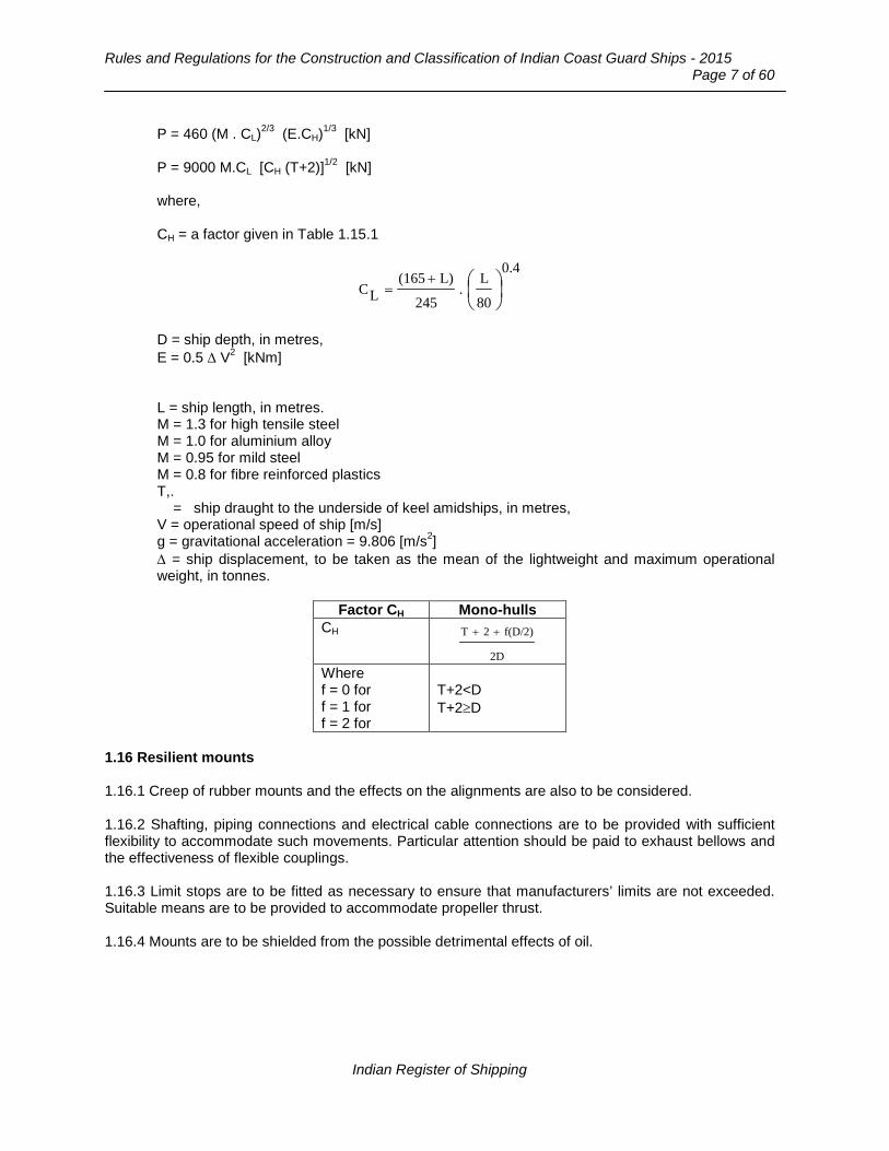
Rules and Regulations for the Construction and Classification of Indian Coast Guard Ships - 2015
Page 7 of 60
P = 460 (M . CL)2/3 (E.CH)1/3 [kN] P = 9000 M.CL [CH (T+2)]1/2 [kN] where, CH = a factor given in Table 1.15.1
0.4
80
L.
245
L)(165LC
+
=
D = ship depth, in metres, E = 0.5 ∆ V2 [kNm] L = ship length, in metres. M = 1.3 for high tensile steel M = 1.0 for aluminium alloy M = 0.95 for mild steel M = 0.8 for fibre reinforced plastics T,. = ship draught to the underside of keel amidships, in metres, V = operational speed of ship [m/s] g = gravitational acceleration = 9.806 [m/s2] ∆ = ship displacement, to be taken as the mean of the lightweight and maximum operational weight, in tonnes.
Factor CH Mono-hulls
CH
2D
f(D/2)2T ++
Where f = 0 for f = 1 for f = 2 for
T+2<D T+2≥D
1.16 Resilient mounts 1.16.1 Creep of rubber mounts and the effects on the alignments are also to be considered. 1.16.2 Shafting, piping connections and electrical cable connections are to be provided with sufficient flexibility to accommodate such movements. Particular attention should be paid to exhaust bellows and the effectiveness of flexible couplings. 1.16.3 Limit stops are to be fitted as necessary to ensure that manufacturers’ limits are not exceeded. Suitable means are to be provided to accommodate propeller thrust. 1.16.4 Mounts are to be shielded from the possible detrimental effects of oil.
Indian Register of Shipping

Chapter 12 : Main and Auxiliary Machinery
Page 8 of 60 __________________________________________________________________________________
1.17 Machinery mounted on resin chocks 1.17.1 These Rules relate to the application of synthetic resin compounds as materials for chocks under machinery components where accurate alignments is important, e.g. main engine, gearbox and auxiliary installations where the engine and generator do not share a common baseplate. 1.17.2 Resin compounds used in these applications are to be of a type accepted by IRS. 1.17.3 The use of resin for chocking gas turbine casings or similar high temperature applications will not be considered. 1.18 Ventilation system 1.18.1 Machinery spaces are to be adequately ventilated so as to ensure that when machinery therein is operating at full power in all weather conditions including heavy weather, an adequate supply of air is maintained. Ventilation system is to be adequate to ensure that safe operation of the ship is not put at risk. 1.18.2 Ventilation to be sufficient under all normal conditions to prevent accumulation of oil vapour. 1.19 Recovery from dead ship condition 1.19.1 Means shall be provided to ensure that machinery can be brought into operation from the dead ship condition without external aid. 1.19.2 The arrangements for bringing main and auxiliary machinery into operation are to have a capacity such that the starting energy and any power supplies for engine operation are available within 30 minutes of dead ship condition. 1.20 Operating conditions 1.20.1 The requirements of 1.13 do not apply to ships of less than 150 GT. 1.20.2 If operation under the required accelerations cannot be demonstrated on trials, alternative documentary evidence is to be presented to confirm that the machinery is capable of operating under such conditions. 1.20.3 Additional trials or conditions may be imposed to prove the machinery as considered necessary. 1.21 Securing of machinery 1.21.1 Ships of less than 150 GT do not have to comply with 1.15. These ship are, in general, to have rigid engine seatings constructed integral with the ship. The arrangements are to permit easy access to any fittings such as lubricating oil connections, bilge suctions and sea cocks. 1.21.2 Where the hull is constructed of FRP, wood or composites and the hull surfaces are not adequately protected against oil contamination, drip trays are to be fitted under those parts of the engine and gearbox where leakage of oil fuel or lubricating oil might occur. Means are to be provided for removing any leakage easily. 1.21.3 Where resilient mounts are fitted, the name of the manufacturer and details of the type of mounting are to be indicated on the plan of the shafting. 1.21.4 Satisfactory arrangements are to be made to transmit the propulsion thrust into the ship structure.
Indian Register of Shipping

Rules and Regulations for the Construction and Classification of Indian Coast Guard Ships - 2015
Page 9 of 60
1.22 Ventilation of machinery spaces 1.22.1 For ships of less than 150 GT the ventilation of the machinery space is to be adequate for all conditions of the operation of the machinery and in no case is to be less than that required by the engine manufacturer. 1.22.2 The engine compartment is to be provided with inlet and outlet ventilating ducts. One or more inlet ducts are to extend down to a suitable low level. 1.22.3 Outlet ducts are to be connected near or at the top of the compartment and are to be arranged for natural or mechanical extraction as necessary. 1.22.4 Consideration will be given to equivalent alternative arrangements provided full details are submitted before construction is commenced. 1.23 Surveys during construction 1.23.1 Machinery is to be surveyed at the manufacturer’s works from the commencement of work until the final test under working conditions. The Surveyors are to be satisfied that the materials, workmanship and arrangements are satisfactory and in accordance with the Rules. 1.23.2 IRS requirements for the conditions of manufacture, survey and certification of materials used for the production of forged steel and castings used in the production of components are given in Chapter 2. 1.23.3 Resilient mounts are to be installed under survey and the machinery tested under full working conditions. 1.23.4 Alignment of machinery is to be checked after the first six months of operation. 1.24 Sea trials 1.24.1 Sea trials are to be of sufficient duration and carried out under normal operating conditions applicable to the intended class notation. 1.24.2 Sea trials are to include the demonstration of:
a) The adequacy of the starting arrangements of the main engines, auxiliary systems and emergency generators.
b) The effectiveness of the steering gear control systems. c) Manoeuvring, to include:
− Starting; − Normal and emergency stopping; − Reversing; − governor testing; − Safety devices and associated indicators and alarms.
Indian Register of Shipping

Chapter 12 : Main and Auxiliary Machinery
Page 10 of 60 __________________________________________________________________________________
d) The redundancy arrangements e) Tooth contact markings in geared installations using a recognized technique. The marking is to
be as detailed in 3.3.2.10. f) For controllable pitch propellers, the pitch setting under failure conditions.
1.24.3 It is to be verified that the propeller performs satisfactorily under ahead and astern conditions. Where controllable pitch propellers are fitted, the free route astern trial is to be carried out with the propeller blades set in the full pitch astern condition. 1.24.4 It is to be verified that large movements of resiliently mounted machinery do not occur during start up and stop, or during normal operating conditions. 1.24.5 The installation should be tested to ensure that gas turbines can not be continuously operated within any speed range where excessive vibration, stalling or surging may be encountered. 1.24.6 Overloading of machinery is not to occur under continuous astern power.
Section 2
Propulsion Shafting Systems
2.1 General requirements Application 2.1.1 This section is to be read in conjunction with the general requirements for Machinery in section 1. 2.1.2 This section gives the requirements for the dimensions of transmission shafts, other than gearing, crankshaft and turbine shafts, couplings, coupling bolts, keys, key ways, stern bushes and other associated components of main propulsion shafting. 2.1.3 The diameters may require to be modified as a result of alignment considerations and vibration characteristics or the inclusion of stress raisers, other than those contained in this section. 2.2 Power ratings 2.2.1 For determining the dimensions of main propulsion components power P is in kW and R in revolutions per minute of the component. 2.3 Clutches 2.3.1 Clutches for single engine propulsion plants in these ships need not be provided with a suitable means for emergency operation in the event of loss of operating fluid systems. 2.4 Safety 2.4.1 Means are to be provided such that in the event of a failure to a shaft or coupling the occupants of the ship are not endangered, either directly or by damaging the ship or its systems. Where necessary, guards may be fitted to achieve compliance with these requirements.
Indian Register of Shipping
Rules and Regulations for the Construction and Classification of Indian Coast Guard Ships - 2015
Page 11 of 60
2.5 Plans 2.5.1 At least three copies of the following plans are to be submitted:
− Shafting arrangement − Thrust shaft − Intermediate shafting − Tube shaft, where applicable − Screw shaft − Screw shaft oil gland − Screw shaft protection − Sternbush and arrangement in housing − Couplings − Coupling bolts − Flexible coupling − Cardan shafts. − All shafting bearings and bushes indicating allowed tolerances
2.5.2 The shafting arrangement plan is to indicate the relative position of the main engine(s), flywheel, flexible coupling(s), gearing, thrust block, line shafting and bearing(s), stern tube, ‘A’ bracket and propulsion device, as applicable. 2.6 Calculations and specifications 2.6.1 The following calculations and specifications are to be submitted: − Calculations or relevant documentation indicating the suitability of all components for short term
high power operation, where applicable. − Where undertaken as an alternative to the requirements to this chapter, fatigue endurance
calculations of all components according to Section 1. − Vibration analysis and alignment analysis as per Part 4, Chapter 4, Section 8 of the ‘Rules and
Regulations for the Construction and Classification of Steel Ships’. − The material specifications, including the minimum specified tensile strength of each shaft and
coupling component is to be stated. The corrosion fatigue strength of corrosion resistant shaft material need not be submitted if the material is as shown in Table 2.8.1. Where corrosion resistant material not included in Table 2.8.1 is used for unprotected screw shafts the corrosion fatigue strength in sea water is to be stated together with the chemical composition and mechanical properties.
− Where it is proposed to use composite (non-metallic) shafts, details of materials, resin, lay-up procedure and documentary evidence of fatigue endurance strength.
2.7 Materials for shafts 2.7.1 Components are to be manufactured and tested in accordance with the requirements of Part 2 of ‘Rules and Regulations for the Construction and Classification of Steel Ships’. 2.7.2 Where it is proposed to use alloy steel forgings, particulars of the chemical composition, mechanical properties and heat treatment are to be submitted for approval. For main propulsion
Indian Register of Shipping

Chapter 12 : Main and Auxiliary Machinery
Page 12 of 60 __________________________________________________________________________________
shafting, not exposed to sea water, in alloy steels, the specified minimum tensile strength is not to exceed 800 [N/mm2] and for other forgings is not to exceed 1100 [N/mm2]. 2.7.3 Unprotected screw shafts and tube shafts exposed to seawater are in general to be manufactured, from corrosion resistant ferrous or non-ferrous material, such as those indicated in Table 2.8.1. 2.7.4 In the selection of materials for shafts, keys, locking nuts etc., consideration is to be given to their compatibility with the proposed propeller material. 2.7.5 Where shafts are manufactured from composite material the process is to be approved. 2.8 Design and Construction 2.8.1 Fatigue strength analysis 2.8.1.1 As an alternative to the following requirements, a fatigue strength analysis of components can be submitted indicating a factor of safety of 1.5 at the design loads, based on suitable fatigue criteria. The effects of stress concentrations, material properties and operating environment are to be taken into account. 2.8.2 Intermediate shafts 2.8.2.1 The diameter, d, of the intermediate shaft is to be not less than:
where, k = 1.0 for shafts with integral coupling flanges complying with 2.8.8 or shrink fit couplings = 1.10 for shafts with key ways, where the fillet radii in the transverse section of the bottom of the key way are not less than 0.0125d. = 1.10 for shafts with transverse or radial holes where the diameter of the hole does not exceed 0.3d. = 1.20 for shafts with longitudinal slots having a length of not more than 1.4d and a width of not more than 0.2d where d, is determined with k = 1.0. F = 95 for turbine installations, electric propulsion installations and diesel engine installations with slip type couplings. = 100 for other diesel engine installations. P and R are defined in Section 2.2.1. σu = specified minimum tensile strength of the shaft material [N/mm2].
2.8.2.2 Beyond a length of 0.2d from the end of a key way, transverse hole or radial hole and 0.3d from the end of a longitudinal slot, the diameter of the shaft may be gradually reduced to that determined with k = 1.0.
]mm[160
560RPkF d 3
u
+σ
=
Indian Register of Shipping

Rules and Regulations for the Construction and Classification of Indian Coast Guard Ships - 2015
Page 13 of 60
2.8.2.3 For shafts with design features other than stated as above, the value of k will be specially considered. 2.8.3 Thrust shafts 2.8.3.1 The diameter at the collars of the thrust shaft transmitting torque or in way of the axial bearing where a roller bearing is used as a thrust bearing is to be not less than that required for the intermediate shaft in accordance with 2.8.2 with a k value of 1.10. 2.8.3.2 Beyond a length equal to the thrust shaft diameter from the collars, the diameter may be tapered down to that required for the intermediate shaft with a k value of 1.0. For the purpose of the foregoing calculations, σu is to be taken as the minimum tensile strength of the thrust shaft material [N/mm2]. 2.8.4 Screw shafts and tube shafts 2.8.4.1 Screw shafts and tube shafts (i.e. the shaft which passes through the stern tube, but does not carry the propeller), made from carbon manganese steel are to be protected by a continuous bronze liner, where exposed to sea water. Alternatively, the liner may be omitted provided the shaft is arranged to run in an oil lubricated bush with an approved oil sealing gland at the after end. Lengths of shafting between stern tubes and brackets, which are readily visible, may be protected by coatings of an approved type. 2.8.4.2 Means for the protection of screw shafts and tube shafts are not required when the shafts are made of corrosion resistant material. 2.8.4.3 The diameter, dp of the protected forged steel screw shaft immediately forward of the forward face of the propeller boss or, if applicable, the forward face of the screw shaft flange, is to be not less than:
where, k = 1.22 for a shaft carrying a keyless propeller, or where the propeller is attached to an integral flange and where the shaft is fitted with a continuous liner, a coating of an approved type, or is oil lubricated and provided with an approved type of oil sealing gland. = 1.26 for a shaft carrying a keyed propeller and where the shaft is fitted with a continuous liner, a coating of an approved type, or is oil lubricated and provided with an approved type of oil sealing gland. P and R are defined in Section 2.2.1. σu = specified minimum tensile strength of the shaft material [N/mm2] but is not to be taken as greater than 600 [N/mm2].
2.8.4.4 The diameter, dp of the screw shaft determined in accordance with 2.8.4.3 is to extend over a length not less than that to the forward edge of the bearing immediately forward of the propeller or 2.5 dp whichever is the greater. 2.8.4.5 The diameter of the portion of the screw shaft and tube shaft forward of the length required by 2.8.4.3 to the forward end of the stern tube seal is to be determined in accordance with 2.8.4.3 with a k value of 1.15. The change of diameter from that determined with k = 1.22 or 1.26 to that determined
]mm[160
560RPk100d 3
up
+σ
=
Indian Register of Shipping
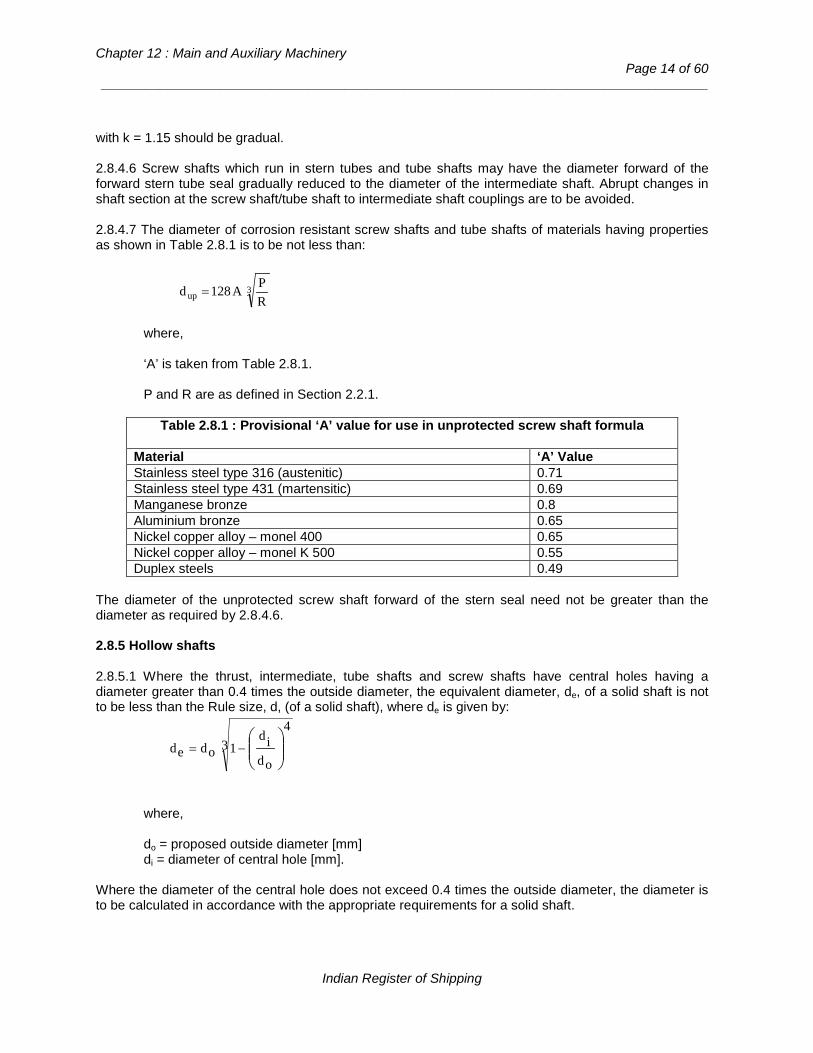
Chapter 12 : Main and Auxiliary Machinery
Page 14 of 60 __________________________________________________________________________________
with k = 1.15 should be gradual. 2.8.4.6 Screw shafts which run in stern tubes and tube shafts may have the diameter forward of the forward stern tube seal gradually reduced to the diameter of the intermediate shaft. Abrupt changes in shaft section at the screw shaft/tube shaft to intermediate shaft couplings are to be avoided. 2.8.4.7 The diameter of corrosion resistant screw shafts and tube shafts of materials having properties as shown in Table 2.8.1 is to be not less than:
where, ‘A’ is taken from Table 2.8.1. P and R are as defined in Section 2.2.1.
Table 2.8.1 : Provisional ‘A’ value for use in unprotected screw shaft formula
Material ‘A’ Value Stainless steel type 316 (austenitic) 0.71 Stainless steel type 431 (martensitic) 0.69 Manganese bronze 0.8 Aluminium bronze 0.65 Nickel copper alloy – monel 400 0.65 Nickel copper alloy – monel K 500 0.55 Duplex steels 0.49
The diameter of the unprotected screw shaft forward of the stern seal need not be greater than the diameter as required by 2.8.4.6. 2.8.5 Hollow shafts 2.8.5.1 Where the thrust, intermediate, tube shafts and screw shafts have central holes having a diameter greater than 0.4 times the outside diameter, the equivalent diameter, de, of a solid shaft is not to be less than the Rule size, d, (of a solid shaft), where de is given by:
where, do = proposed outside diameter [mm] di = diameter of central hole [mm].
Where the diameter of the central hole does not exceed 0.4 times the outside diameter, the diameter is to be calculated in accordance with the appropriate requirements for a solid shaft.
3up RPA128d =
34
odid
1oded
−=
Indian Register of Shipping
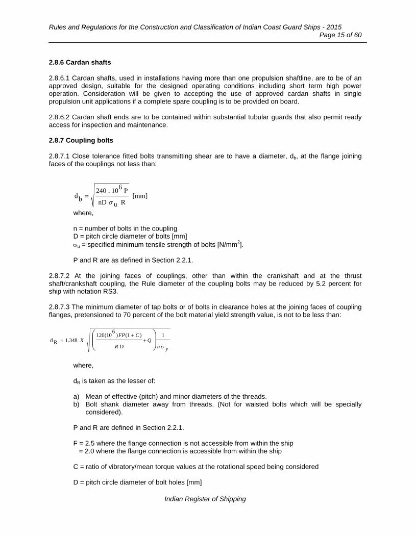
Rules and Regulations for the Construction and Classification of Indian Coast Guard Ships - 2015
Page 15 of 60
2.8.6 Cardan shafts 2.8.6.1 Cardan shafts, used in installations having more than one propulsion shaftline, are to be of an approved design, suitable for the designed operating conditions including short term high power operation. Consideration will be given to accepting the use of approved cardan shafts in single propulsion unit applications if a complete spare coupling is to be provided on board. 2.8.6.2 Cardan shaft ends are to be contained within substantial tubular guards that also permit ready access for inspection and maintenance. 2.8.7 Coupling bolts 2.8.7.1 Close tolerance fitted bolts transmitting shear are to have a diameter, db, at the flange joining faces of the couplings not less than:
where, n = number of bolts in the coupling D = pitch circle diameter of bolts [mm] σu = specified minimum tensile strength of bolts [N/mm2]. P and R are as defined in Section 2.2.1.
2.8.7.2 At the joining faces of couplings, other than within the crankshaft and at the thrust shaft/crankshaft coupling, the Rule diameter of the coupling bolts may be reduced by 5.2 percent for ship with notation RS3. 2.8.7.3 The minimum diameter of tap bolts or of bolts in clearance holes at the joining faces of coupling flanges, pretensioned to 70 percent of the bolt material yield strength value, is not to be less than:
ynQ
DR
CFPX
σ
1)1()6
10(120348.1Rd
+
+=
where, dR is taken as the lesser of: a) Mean of effective (pitch) and minor diameters of the threads. b) Bolt shank diameter away from threads. (Not for waisted bolts which will be specially
considered). P and R are defined in Section 2.2.1. F = 2.5 where the flange connection is not accessible from within the ship = 2.0 where the flange connection is accessible from within the ship C = ratio of vibratory/mean torque values at the rotational speed being considered D = pitch circle diameter of bolt holes [mm]
[mm]RunD
P610.240bd
σ=
Indian Register of Shipping

Chapter 12 : Main and Auxiliary Machinery
Page 16 of 60 __________________________________________________________________________________
Q = external load on in N n = number of tap or clearance bolts σy = bolt material yield stresses [N/mm2].
2.8.7.4 Consideration will be given to those arrangements where the bolts are pretensioned to loads other than 70 percent of the material yield strength. 2.8.8 Flange connections of couplings 2.8.8.1 The minimum thicknesses of the coupling flanges are to be equal to the diameters of the coupling bolts at the face of the couplings as required by 2.8.7.1, and for this purpose the minimum tensile strength of the bolts is to be taken as equivalent to that of the shafts. For intermediate, thrust shafts and the inboard end of the screw shaft, the thickness of the coupling flange is in no case to be less than 0.20 of the diameter of the intermediate shaft as required by 2.8.2.1. 2.8.8.2 The fillet radius at the base of the coupling flange, integral with the shaft, is to be not less than 0.08 of the diameter of the shaft at the coupling. The fillets are to have a smooth finish and are not to be recessed in way of nut and bolt heads. 2.8.8.3 Where the propeller is attached by means of a flange, the thickness of the flange is to be not less than 0.25 of the actual diameter of the adjacent part of the screw shaft. The fillet radius at the base of the coupling flange is to be not less than 0.125 of the diameter of the shaft at the coupling. 2.8.8.4 All couplings which transmit torque are to be of approved dimensions. 2.8.8.5 Where couplings are separate from the shafts, provision is to be made to resist the astern pull. 2.8.8.6 Where a coupling is shrunk on to the parallel portion of a shaft or is mounted on a slight taper, e.g. by means of the oil pressure injection method, the assembly is to meet the requirements of 2.8.11. 2.8.9 Tooth couplings 2.8.9.1 The contact stress, σc, at the flanks of mating teeth of a gear coupling is not to exceed that given in Table below, where:
]2[N/mmbhzpRd
P610x24=
cσ
Where P and R are as defined in 2.2.1. dp = pitch circle diameter of coupling teeth [mm] b = tooth facewidth [mm] h = tooth height [mm] z = number of teeth (per coupling half).
Allowable σc values Tooth material surface treatment Allowable σc value
[N/mm2] Surface hardened teeth 19 Through hardened teeth 11
Indian Register of Shipping
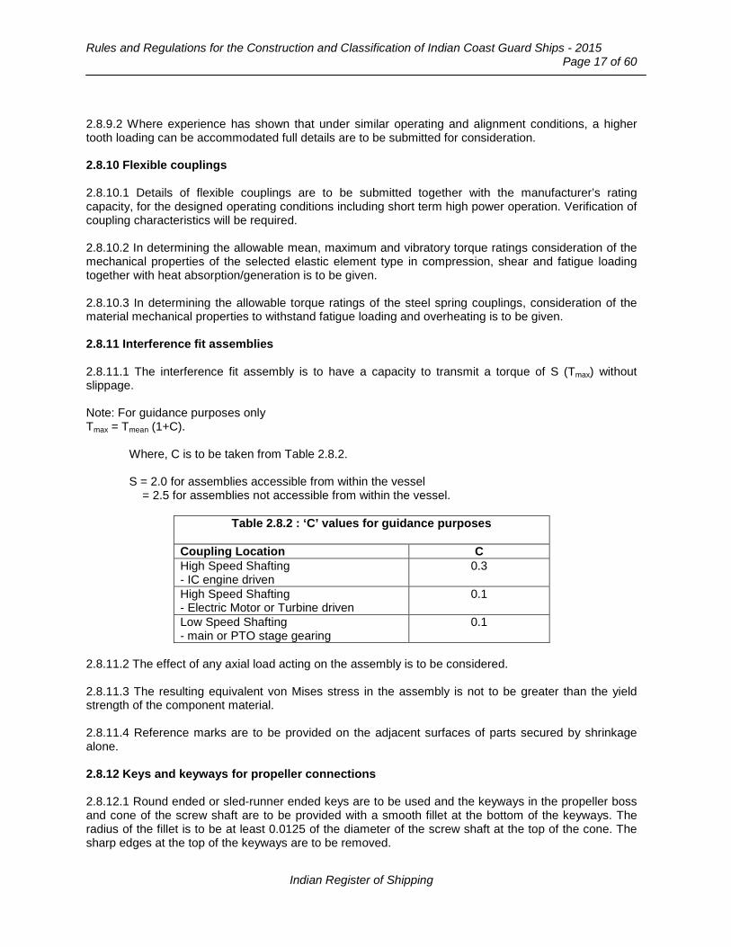
Rules and Regulations for the Construction and Classification of Indian Coast Guard Ships - 2015
Page 17 of 60
2.8.9.2 Where experience has shown that under similar operating and alignment conditions, a higher tooth loading can be accommodated full details are to be submitted for consideration. 2.8.10 Flexible couplings 2.8.10.1 Details of flexible couplings are to be submitted together with the manufacturer’s rating capacity, for the designed operating conditions including short term high power operation. Verification of coupling characteristics will be required. 2.8.10.2 In determining the allowable mean, maximum and vibratory torque ratings consideration of the mechanical properties of the selected elastic element type in compression, shear and fatigue loading together with heat absorption/generation is to be given. 2.8.10.3 In determining the allowable torque ratings of the steel spring couplings, consideration of the material mechanical properties to withstand fatigue loading and overheating is to be given. 2.8.11 Interference fit assemblies 2.8.11.1 The interference fit assembly is to have a capacity to transmit a torque of S (Tmax) without slippage. Note: For guidance purposes only Tmax = Tmean (1+C).
Where, C is to be taken from Table 2.8.2. S = 2.0 for assemblies accessible from within the vessel = 2.5 for assemblies not accessible from within the vessel.
Table 2.8.2 : ‘C’ values for guidance purposes
Coupling Location C High Speed Shafting - IC engine driven
0.3
High Speed Shafting - Electric Motor or Turbine driven
0.1
Low Speed Shafting - main or PTO stage gearing
0.1
2.8.11.2 The effect of any axial load acting on the assembly is to be considered. 2.8.11.3 The resulting equivalent von Mises stress in the assembly is not to be greater than the yield strength of the component material. 2.8.11.4 Reference marks are to be provided on the adjacent surfaces of parts secured by shrinkage alone. 2.8.12 Keys and keyways for propeller connections 2.8.12.1 Round ended or sled-runner ended keys are to be used and the keyways in the propeller boss and cone of the screw shaft are to be provided with a smooth fillet at the bottom of the keyways. The radius of the fillet is to be at least 0.0125 of the diameter of the screw shaft at the top of the cone. The sharp edges at the top of the keyways are to be removed.
Indian Register of Shipping

Chapter 12 : Main and Auxiliary Machinery
Page 18 of 60 __________________________________________________________________________________
2.8.12.2 Two screwed pins are to be provided for securing the key in the keyway and the forward pin is to be placed at least one-third of the length of the key from the end. The depth of the tapped holes for the screwed pins is not to exceed the pin diameter and the edges of the holes are to be slightly bevelled. The omission of pins for keys for small diameter shafts will be specially considered. 2.8.12.3 The distance between the top of the cone and the forward end of the keyway is to be not less than 0.2 of the diameter of the screw shaft at the top of the cone. 2.8.12.4 The effective sectional area of the key in shear, is to be not less than:
where, d = diameter [mm] required for the intermediate shaft determined in accordance with 2.8.2, based on material having a specified minimum tensile strength of 400 [N/mm2] and k = 1. d1 = diameter of shaft at mid length of the key [mm]. σu = specified minimum tensile strength (UTS) of the key material [N/mm2].
The effective area in crushing of key, shaft or boss is to be not less than:
where,
σy = yield strength of key, shaft or boss material as appropriate [N/mm2].
2.8.13 Keys and keyways for inboard shaft connections 2.8.13.1 Round ended keys are to be used and the keyways are to be provided with a smooth fillet at the bottom of the keyways. The radius of the fillet is to be at least 0.0125 of the diameter of the shaft at the coupling. The sharp edges at the top of the keyways are to be removed. 2.8.13.2 The effective area of the key in shear, A, is to be not less than:
where, d = diameter [mm], required for the intermediate shaft determined in accordance with 2.8.2, based on material having a specified minimum tensile strength of 400 [N/mm2] and k=1 d1 = diameter of shaft at mid-length of the key [mm] σu = specified minimum tensile strength (UTS) of the key material [N/mm2].
]mm[dd155 2
1u
3
σ
]mm[dd24 2
1y
3
σ
]mm[dd126 A 2
1u
3
σ=
Indian Register of Shipping

Rules and Regulations for the Construction and Classification of Indian Coast Guard Ships - 2015
Page 19 of 60
2.8.14 Corrosion resistant liners on shafts 2.8.14.1 Liners may be bronze, gunmetal, stainless steel or other approved alloy. 2.8.14.2 The thickness, t of liners fitted on screw shafts or on tube shafts, in way of the bushes, is to be not less, when new, than given by the following formula:
[mm]32
230 D t
+=
where, t = thickness of the liner [mm] D = diameter of the screw shaft or tube shaft under the liner [mm]. The thickness of a continuous liner between the bushes is to be not less than 0.75t.
2.8.14.3 Continuous liners are to be fabricated or cast in one piece. 2.8.14.4 Where liners consist of two or more lengths, these are to be butt welded together. In general, the lead content of the gunmetal of each length forming a butt welded liner is not to exceed 0.5 percent. The composition of the electrodes or filler rods is to be substantially lead-free. 2.8.14.5 The circumferential butt welds are to be of multi-run, full penetration type. Provision is to be made for contraction of the weld by arranging for a suitable length of the liner containing the weld, if possible about three times the shaft diameter, to be free of the shaft. To prevent damage to the surface of the shaft during welding, a strip of heat resisting material covered by a copper strip should be inserted between the shaft and the liner in way of the joint. Other methods for welding this joint may be accepted if approved. The welding is to be carried out by an approved method and to the Surveyor’s satisfaction. 2.8.14.6 Each continuous liner or length of liner is to be tested by hydraulic pressure to 2.0 bar after rough machining. 2.8.14.7 Liners are to be carefully shrunk on to the shafts by hydraulic pressure. Pins are not to be used to secure the liners. 2.8.14.8 Effective means are to be provided for preventing water from reaching the shaft at the part between the after end of the liner and the propeller boss. 2.8.14.9 If the liner does not fit the shaft tightly between the bearing portions in the stern tube, the space between the shaft and the liner is to be fitted with a plastic insoluble non-corrosive compound. 2.8.15 Stern bushes and stern tube arrangement 2.8.15.1 Where the sterntube or sternbushes are to be installed using a resin, of an approved type, the following requirements are to be met:
a) Pouring and venting holes are to be provided at opposite ends with the vent hole at the highest point.
b) The minimum radial gap occupied by the resin is to be not less than 6 mm at any one point with a nominal resin thickness of 12 mm.
Indian Register of Shipping

Chapter 12 : Main and Auxiliary Machinery
Page 20 of 60 __________________________________________________________________________________
c) In the case of oil lubricated sterntube bearings, the arrangement of the oil grooves is to be such
as to promote a positive circulation of oil in the bearing.
d) Provision is to be made for the remote measurement of the temperature at the aft end of the aft bearing, with indication and alarms at the control stations.
2.8.15.2 The length of the bearing in the sternbush next to and supporting the propeller is to be as follows:
a) For water lubricated bearings which are lined with rubber composition or staves of approved plastics material, the length is to be not less than four times the diameter required for the screw shaft under the liner.
b) For water lubricated bearings lined with two or more circumferentially spaced sectors, of an
approved plastics material, without axial grooves in the lower half, the length of the bearing is to be such that the nominal bearing pressure will not exceed 0.55 [N/mm2]. The length of the bearing is to be not less than twice its diameter.
c) For bearings which are white-metal lined, oil lubricated and provided with an approved type of
oil sealing gland, the length of the bearing is to be approximately twice the diameter required for the screw shaft and is to be such that the nominal bearing pressure will not exceed 0.8 [N/mm2]. The length of the bearing is to be not less than 1.5 times its diameter.
d) For bearings of cast iron and bronze which are oil lubricated and fitted with an approved oil
sealing gland, the length of the bearing is, in general, to be not less than four times the diameter required for the screw shaft.
e) Non metallic bearings are to be manufactured from approved material.
2.8.15.3 Sternbushes are to be adequately secured in housings. 2.8.15.4 Forced water lubrication is to be provided for all bearings lined with rubber or plastics. The supply of water may come from a circulating pump or other pressure source. Flow indicators are to be provided for the water service to plastics and rubber bearings. The water grooves in the bearings are to be of ample section and of a shape which will be little affected by weardown, particularly for bearings of the plastics type. 2.8.15.5 The shut-off valve or cock controlling the supply of water is to be fitted direct to the after peak bulkhead, or to the sterntube where the water supply enters the sterntube forward of the bulkhead. 2.8.15.6 Oil sealing glands must be capable of accommodating the effects of differential expansion between hull and line of shafting for all sea temperatures in the proposed area of operation. This requirement applies particularly to those glands which span the gap and maintain oiltightness between the sterntube and the propeller boss. 2.8.15.7 Where a tank supplying lubricating oil to the sternbush is fitted, it is to be located above the load waterline and is to be provided with a low level alarm device in the machinery space. See also 2.11.1. 2.8.15.8 Where sternbush bearings are oil lubricated, provision is to be made for cooling the oil by maintaining water in the after peak tank above the level of the sterntube or by other approved means. Means for ascertaining the temperature of the oil in the sterntube are also to be provided.
Indian Register of Shipping

Rules and Regulations for the Construction and Classification of Indian Coast Guard Ships - 2015
Page 21 of 60
2.8.15.9 Where In-Water-Survey is proposed to be carried out means are to be provided for ascertaining the clearance in the sternbush with the vessel afloat. 2.8.15.10 For ships of less than 150 GT, the requirements of 2.8.15.6 and 2.8.15.8 do not apply. Stern tube bearings of approved plastics materials are to be so designed as to ensure an adequate supply of water for lubrication. 2.8.15.11 The aftermost propeller shaft bearing in the stern tube is to be secured to prevent rotational and axial movement. 2.9 Vibration and alignment 2.9.1 For the requirements for torsional, axial and lateral vibration and for alignment of the shafting, see Part 4, Chapter 4, Section 8 of the ‘Rules and Regulations for the Construction and Classification of Steel Ships’. 2.10 Protection of propeller shafts 2.10.1 In monohulls, propeller shaft and bearings of at least one main engine, when passing through the aft machinery space, are to be protected as follows:
a) steel shaft bearings by water spray, b) shafts made of composite material (FRP), either by
i) passive fire protection for 60 minutes duration, or ii) a water spray system and able to transmit the full torque of the propulsion engine after a standard fire test of 7 minutes.
2.11 Control and Monitoring 2.11.1 Unattended machinery 2.11.1.1 Where sterntube lubrication oil systems are fitted with automatic or remote controls so that under normal operating conditions they do not require any manual intervention by the operators, they are to be provided with the alarms indicated in Table 2.11.1. These requirements do not apply to ships less than 500 GT.
Table 2.11.1 : Alarms
Item Alarm Sterntube lubricating oil tank level
Low
Sterntube bearing temperature (oil lubricated)
High
2.12 Construction 2.12.1 Boring of the sternframe, fitting of the sterntube and bearings and aligning the shafting are to be carried out to a formal traceable procedure. 2.12.2 Before boring the sternframe the structural steel work should be generally complete to the upper deck and to the engine room forward bulkhead.
Indian Register of Shipping
Chapter 12 : Main and Auxiliary Machinery
Page 22 of 60 __________________________________________________________________________________
Section 3
Prime Mover and Gearing
3.1 Diesel Engines 3.1.1 General Requirements 3.1.1.1 Application 3.1.1.1.1 This section is to be read in conjunction with the General Requirements for Machinery in Section 1. 3.1.1.1.2 The requirements of crankshaft design do not apply to diesel engines intended for essential services where power does not exceed 100 [kW]. 3.1.1.2 Power ratings 3.1.1.2.1 For determining the dimensions of main propulsion components power P is in kW and R in revolutions per minute of the component. 3.1.1.3 Power conditions for generator sets 3.1.1.3.1 Auxiliary engines coupled to electrical generators are to be capable under service conditions of developing continuously the power to drive the generators at full rated output (kW) and of developing for a short period (15 minutes) an overload power of not less than 10 percent (See Chapter 13). 3.1.1.4 Inclination of ship 3.1.1.4.1 Main and essential auxiliary diesel engines are to operate satisfactorily under the conditions as shown in Table 1.13.1 in Section 1. The requirements for inclination are not to be applied to Ships less than 150 GT. 3.1.1.5 Engine type testing 3.1.1.5.1 New engine types or developments of existing types are to be subjected to an agreed programme of type testing to complement the design appraisal and review of documentation. The programme will need to include short term high power operation where applicable. 3.1.1.6 Plans and information 3.1.1.6.1 At least three copies of the following plans are to be submitted:
- Crankshaft assembly plan. - Crankshaft details plan - Thrust shaft. - Thrust bearing assembly. - Coupling bolts. - Counterweights, where attached to crankthrow. - Main engine holding down arrangement. - Type and arrangement of crankcase explosion relief valves. - Details of the securing and collision arrangements.
Indian Register of Shipping

Rules and Regulations for the Construction and Classification of Indian Coast Guard Ships - 2015
Page 23 of 60
- Schematic oil fuel system, including controls and safety devices. - Lubricating oil system. - Starting air system. - Cooling water system. - Control engineering aspects in accordance with Chapter 14. - Shielding of high pressure fuel pipes. - Longitudinal and transverse cross-section. - Cast bedplate, crankcase and frames. - Cylinder cover, liner and jacket (or engine block). - Piston assembly. - Tie rod. - Connecting rod, piston rod and crosshead assemblies. - Camshaft drive and camshaft general arrangement. - Shielding and insulation of exhaust pipes. - Details of turbochargers. - Vibration dampers/detuners and moment compensators. - Cross-sectional plans of the assembled turbo-charger with main dimensions. - Fully dimensioned plans of the rotor. - Material particulars with details of welding and surface treatments. - Turbo-charger operating and test data.
3.1.1.6.2 The following information and calculations are to be submitted: - Crankshaft design data as outlined in Part 4, Chapter 4, Section 4 of the ‘Rules and Regulations for
the Construction and Classification of Steel Ships’. This requirements is not applicable for ships having main or auxiliary diesel engines with a power output not exceeding 100 [kW].
- Combustion pressure displacement relationship - Power/speed operational envelope. - Calculations and information for short term high power operation where applicable. - Arrangement and welding specifications with details of the procedures for fabricated bed plate,
crankcases, frames and entablatures. Details of welding consumables, fabrication sequence and heat treatments are to be included.
- Operation and maintenance manuals. - Material specifications covering the listed components together with details of any surface
treatments, non-destructive testing and hydraulic tests. - Arrangement of interior lighting, where provided. - Engine type test programme, where required including proposals for short term high power
operation. - Alternative proposals for hydraulic tests where design features are such that modifications to the
test requirements are necessary. 3.1.1.6.3 Where it is proposed to use alloy castings, micro alloyed or alloy steel forgings or iron castings, details of the chemical composition, heat treatment and mechanical properties are to be submitted. 3.1.1.6.4 For engine types built under licence it is intended that the above documentation be submitted by the Licensor. Each Licensee is then to submit the following: - A list, based on the above, of all documents required with the relevant drawing numbers and
revision status from both Licensor and Licensee. - The associated documents where the Licensee proposes design modifications to components. In
such cases a statement is to be made confirming the Licensor’s acceptance of the proposed changes.
Indian Register of Shipping
Chapter 12 : Main and Auxiliary Machinery
Page 24 of 60 __________________________________________________________________________________
3.1.1.6.5 In all cases a complete set of endorsed documents will be required by the Surveyor attending the Licensee’s works. 3.1.1.6.6 Where considered necessary additional documentation may be required. 3.1.2 Material, design and construction 3.1.2.1 For material test and inspection refer to Part 2 and Part 4 of ‘Rules and Regulations for the Construction and Classification of Steel Ships’. 3.1.2.2 For crankshaft design refer to Part 4, Chapter 4, Section 8 of the ‘Rules and Regulations for the Construction and Classification of Steel Ships’. This requirement is not applicable for ships having main or auxiliary diesel engines with a power output not exceeding 100 [kW]. 3.1.2.3 Requirements of construction of welded structure to meet Part 4, Chapter 4, Section 4 of the ‘Rules and Regulations for the Construction and Classification of Steel Ships’. 3.1.2.4 For crankcase, relief valve, vent pipes, crankcase covers, starting arrangement, air compressor, receiver, starting air pipe and electrical starting refer Part 4, Chapter 4, Section 4 of the ‘Rules and Regulations for the Construction and Classification of Steel Ships’. 3.1.2.5 The requirements for battery installations are given in Chapter 13. 3.1.3 Safety Arrangements on Engines 3.1.3.1 Cylinder relief valves 3.1.3.1.1 Cylinder relief valves are to be fitted to engines having cylinders over 230 [mm] bore. The valves are to be loaded to not more than 40 percent above the designed maximum pressure and are to discharge where no damage can occur. Consideration will be given to any other alternative relief arrangement. 3.1.3.1.2 In the case of auxiliary engines, consideration will be given to the replacement of the relief valve by an efficient warning device of overpressure in the cylinder. 3.1.3.2 Scavenge relief valve 3.1.3.2.1 Scavenge spaces in open connection with cylinders are to be provided with explosion relief valves. 3.1.4 Piping Systems 3.1.4.1 General 3.1.4.1.1 Diesel engine piping systems are, in general, to comply with the requirements of Chapter 11, due regard being paid to the particular type of installation. 3.1.4.1.2 Synthetic rubber hoses, with single or double closely woven integral wire braid reinforcement, or convoluted metal pipes with wire braid protection, may be used in compressed air, fresh water, sea-water, oil fuel and lubricating oil systems. Where synthetic rubber hoses are used for fuel the hoses are to have external wire braid protection in addition to the integral wire braid.
Indian Register of Shipping

Rules and Regulations for the Construction and Classification of Indian Coast Guard Ships - 2015
Page 25 of 60
3.1.4.2 Oil fuel systems 3.1.4.2.1 Oil fuel arrangements are to comply with the requirements of Chapter 11, as applicable. 3.1.4.2.2 On main and auxiliary engines all external high pressure fuel delivering lines between the high pressure fuel pumps and fuel injectors to be protected with a jacketed piping system capable of containing fuel from a high pressure line failure. The jacketed piping system shall include a means of collection of leakages and arrangements to be provided for an alarm to be given of a fuel line failure. 3.1.4.2.3 The protection is to prevent oil fuel or oil fuel mist from reaching a source of ignition on the engine or its surroundings. Suitable drainage arrangements are to be made for draining any oil fuel leakage and for preventing contamination of the lubricating oil by oil fuel. 3.1.4.3 Oil fuel filters and fittings 3.1.4.3.1 Two or more filters are to be fitted in the oil fuel supply lines to the main and auxiliary engines and the arrangements are to be such that any filter can be cleaned without interrupting the supply of filtered oil fuel to the engines. 3.1.4.3.2 Drip trays are to be fitted under oil fuel filters and other fittings which are required to be opened up frequently for cleaning or adjustment or where there is the possibility of leakage. Alternative arrangements may be acceptable and full details should be submitted for consideration. 3.1.4.4 Lubricating oil systems 3.1.4.4.1 Lubricating oil arrangements are to comply with the requirements of Chapter 11 as applicable. 3.1.4.4.2 Where the lubricating oil for main propelling engines is circulated under pressure, provision is to be made for the efficient filtration of the oil. The filters are to be capable of being cleaned without stopping the engine or reducing the supply of filtered oil to the engine. Proposals for an automatic by-pass for emergency purposes in high speed engines are to be submitted for special consideration. 3.1.4.5 Engine cooling water systems 3.1.4.5.1 Cooling water arrangements are to comply with the requirements of Chapter 11, as applicable. 3.1.4.6 Exhaust systems 3.1.4.6.1 Where the exhaust is led overboard near the waterline, means are to be provided to prevent water from being siphoned back to the engine. Where the exhaust is cooled by water spray, the exhaust pipes are to be self draining overboard. Erosion/corrosion resistant shut-off flaps or other devices are to be fitted on the hull side shell or pipe end and acceptable arrangements made to prevent water flooding the space or entering the engine exhaust manifold. 3.1.4.6.2 Where the exhausts of two or more engines are led to a common silencer or exhaust gas heated boiler or economizer, an isolating device is to be provided in each exhaust pipe. 3.1.4.6.3 The arrangement of the exhaust system is to be such as to prevent exhaust gases being drawn into the manned spaces, air conditioning systems and air intakes. They should not discharge into air cushion intakes.
Indian Register of Shipping

Chapter 12 : Main and Auxiliary Machinery
Page 26 of 60 __________________________________________________________________________________
3.1.5 Control and monitoring 3.1.5.1 General 3.1.5.1.1 The control and monitoring systems are to comply with the requirements of Chapter 14. 3.1.5.1.2 While it is recommended that oil mist monitoring or engine bearing temperature monitors for crankcase protection be fitted, they are in any case to be provided:
a) When arrangements are fitted to override the automatic stop for excessive reduction of the lubricating oil supply pressure.
b) For engines of 2,250 kW and above or having cylinders of more than 300 mm bore. 3.1.5.1.3 All main and auxiliary engines intended for essential services are to be provided with means of indicating the lubricating oil pressure supply to them. Where such engines are of more than 220 [kW], audible and visual alarms are to be fitted to give warning of an appreciable reduction in pressure of the lubricating oil supply. Further, these alarms are to be actuated from the outlet side of any restrictions, such as filters, coolers, etc. 3.1.5.2 Main engine governors 3.1.5.2.1 An efficient governor is to be fitted to each main engine so adjusted that the speed does not exceed that for which the engine is to be classed by more than 15 percent. 3.1.5.3 Auxiliary engine governors 3.1.5.3.1 Auxiliary engines intended for driving electric generators are to be fitted with governors which, with fixed setting, are to control the speed within 10 percent momentary variation and 5 percent permanent variation under the following conditions:
a) Full load is suddenly taken off. b) Full load is suddenly applied following a minimum of 15 minutes no load. If the BMEP is greater
than 8 bar the load may be applied as follows:
(but not less than 1/3 full load), then full load being attained in not more than two equal stages as rapidly as possible.
3.1.5.3.2 Emergency engines are to comply with above except that the initial load required by above is to be not less than the total connected emergency statutory load. 3.1.5.3.3 For alternating current installations, the permanent speed variation of the machines intended for parallel operation are to be equal within a tolerance of ± 0.5 percent. Momentary speed variations with load changes in accordance with above are to return to and remain within one percent of the final steady state speed in not more than eight seconds. 3.1.5.4 Overspeed protective devices 3.1.5.4.1 Each main engine developing 200 [kW] or over which can be declutched or which drives a controllable (reversible) pitch propeller, also each auxiliary engine developing 200 [kW] and over for driving an electric generator, is to be fitted with an approved overspeed protective device.
%BMEP
800
Indian Register of Shipping

Rules and Regulations for the Construction and Classification of Indian Coast Guard Ships - 2015
Page 27 of 60
Table 3.1.5.1
Item Alarm Note Lubricating oil sump level Low - Lubricating oil inlet pressure++ 1st stage Low++
2nd stage Low Engines (and gearing if fitted) Automatic shutdown engines (and gearing if fitted) 3.1.5.6.2
Lubricating oil inlet temperature* High Engines (and gearing if fitted) Lubricating oil filters differential pressure
High -
Cylinder lubricator flow Low unit One sensor per lubricator Piston coolant inlet pressure Low If a separate system Piston coolant outlet temperature*
High Per cylinder (if a separate system)
Piston coolant outlet flow Low Per cylinder (if a separate system)
Cylinder coolant inlet pressure or flow*++
Low -
Cylinder coolant outlet temperature*++
1st stage High++ 2nd stage High
Per cylinder (if a separate system) or manifold++ Automatic shutdown medium and high speed engines, 3.1.5.6.2
Sea water cooling pressure Low - Thrust bearing temperature* High - Fuel valve coolant pressure Low If a separate system Fuel valve coolant, temperature High If a separate system Oil fuel pressure from booster pump
Low -
Oil fuel temperature or viscosity High and Low Heavy oil only Charge air cooler outlet temperature
High and Low 4 stroke medium and high speed engines
Scavenge air temperature High Per cylinder (fire detection, 2 stroke engines)
Exhaust gas temperature High Per cylinder (or deviation from average temperature)
Turbo-charger exhaust gas outlet temperature*
High -
Turbo-charger lubricating oil inlet pressure
Low If system not integral with turbo-charger
Turbo-charger lubricating oil inlet temperature
High If system not integral with turbo-charger
Starting air pressure* Low Before engine manoeuvring valve
Overspeed High See 3.1.5.4 Automatic start of engine Failure See 3.1.6.6 Notes: 1. Where ‘per cylinder’ appears in this table, suitable alarms maybe situated on manifold outlets for
medium and high speed engines 2. For engines of 1500 kW or less only the items marked * are required. 3. For ships with engines of 500 kW or less, only the items marked ++ are required.
Indian Register of Shipping

Chapter 12 : Main and Auxiliary Machinery
Page 28 of 60 __________________________________________________________________________________
3.1.5.4.2 The overspeed protective device, including its driving mechanism, is to be independent of the governor required by 3.1.5.2 or 3.1.5.3 and is to be so adjusted that the speed does not exceed that for which the engine and its driven machinery are to be classed by more than 20 percent for main engines and 15 percent for auxiliary engines. 3.1.5.5 Engine stopping 3.1.5.5.1 At least two independent means of stopping the engines quickly from the control station under any conditions is to be available. 3.1.5.6 Unattended machinery 3.1.5.6.1 Where machinery, is fitted with automatic or remote controls so that under normal operating conditions it does not require any manual intervention by the operators, it is to be provided with the alarms and safety arrangements required by 3.1.5 to 3.1.6 as appropriate. Alternative arrangements which provide equivalent safeguards will be considered. 3.1.5.6.2 Where a first stage alarm together with a second stage alarm and automatic shutdown of machinery are required by Tables 3.1.5.1 and 3.1.5.2, the sensors and circuits utilised for the second stage alarm and automatic shutdown are to be independent of those required for the first stage alarm. 3.1.5.6.3 Means are to be provided to prevent leaks from high pressure oil fuel injection piping for main and auxiliary engines dripping or spraying onto hot surfaces or into machinery air inlets. Such leakage should be led to a collector tank(s) fitted in a safe position with an alarm to indicate that leakage is taking place. These requirements may also be applicable to high pressure hydraulic oil piping depending upon the location. 3.1.6 Diesel engines for propulsion purposes 3.1.6.1 Alarms and safeguards are indicated in Table 3.1.5.1. See also 3.1.5.1.2 and 3.1.5.1.3. 3.1.6.2 Alarms are to operate and indication is to be given at the relevant control stations that the speed or power of the main propulsion engine(s) is to be reduced for the following fault conditions:
a) Oil mist in crankcase or high bearing temperature (if detection is fitted 3.1.5.1.2). b) Low piston coolant pressure or flow. c) High piston coolant outlet temperature. d) Low cylinder coolant pressure or flow. e) High cylinder coolant temperature. f) High exhaust gas temperature per cylinder or deviation from average temperature (high).
3.1.6.3 Reduction of speed or power may be effected by either manual or automatic control. 3.1.6.4 The following engine services are to be fitted with automatic temperature controls so as to maintain steady state conditions throughout the normal operating range of the propulsion engine(s):
a) Lubricating oil supply. b) Piston coolant supply, where applicable. c) Cylinder coolant supply, where applicable. d) Fuel valve coolant supply, where applicable.
3.1.6.5 Indication of the starting air pressure is to be provided at each control station from which it is possible to start the main propulsion engine(s).
Indian Register of Shipping

Rules and Regulations for the Construction and Classification of Indian Coast Guard Ships - 2015
Page 29 of 60
3.1.6.6 The number of automatic consecutive attempts which fail to produce a start is to be limited to three attempts. For reversible engines which are started and stopped for manoeuvring purposes, means are to be provided to maintain sufficient starting air in the air receivers. For electric starting, see Part 4, Chapter 4, Section 4, Clause 4.11 of the ‘Rules and Regulations for the Construction and Classification of Steel Ships’. 3.1.6.7 Prolonged running in a restricted speed range is to be prevented automatically or, alternatively, an indication of restricted speed ranges is to be provided at each control station. 3.1.7 Auxiliary and other engines 3.1.7.1 Alarms and safeguards are indicated in Table 3.1.5.2. See also 3.1.5.1.2 and 3.1.5.6.3.
Table 3.1.5.2
Item Alarm Note
Lubricating oil inlet temperature High -
Lubricating oil inlet pressure 1st stage Low 2nd stage Low
- Automatic shutdown of engine*, see 3.1.5.6.2
Coolant outlet temperature
1st stage High 2nd stage High
For engines over 200 kW For engines over 200 kW Automatic shutdown of engine*, see 3.1.5.6.2
Coolant pressure or flow Low - Overspeed High See 3.1.5.4 Starting air pressure Low - Notes: 1. There are no classification requirements for the items marked* in the case of engines being used for
the emergency source of electrical power required by SOLAS. 2. The arrangements are to comply with the requirements of the National Authority concerned.
3.1.8 Materials 3.1.8.1.1 Materials for which no provision is made in this part of the Rules may be accepted provided that they comply with an approved specification and such tests as may be considered necessary. 3.1.9 Turbochargers 3.1.9.1 A type test is to consist of hot gas running test of at least one hour duration at the maximum permissible speed and maximum permissible temperature. Following the test the turbo-charger is to be completely dismantled for examination of all parts. Alternative arrangements will be considered. 3.1.9.2 All rotors are to be dynamically balanced on final assembly to the Surveyor’s satisfaction. 3.1.9.3 All fully bladed rotor sections and impeller/inducer wheels are to be over-speed tested for three minutes at either 20 percent above the maximum permissible speed at room temperature or 10 percent above the maximum permissible speed at the normal working temperature.
Indian Register of Shipping
Chapter 12 : Main and Auxiliary Machinery
Page 30 of 60 __________________________________________________________________________________
3.1.9.4 Turbo-chargers are to be given a mechanical running test of 20 minutes duration at the maximum permissible speed. 3.1.9.5 Upon application, with details of an historical audit covering previous testing of turbo-chargers manufactured under an approved quality assurance scheme, consideration will be given to confining the test to a representative sample of turbo-chargers. 3.2 Gas Turbine 3.2.1 General Requirements The requirements of this sub-section are applicable to gas turbines for main propulsion and essential machinery. 3.2.1.1 Power ratings 3.2.1.1.1 For determining the dimensions of main propulsion components power P is in kW and R in revolutions per minute of the component. 3.2.1.2 Power conditions for generator sets 3.2.1.2.1 Auxiliary gas turbines coupled to electrical generators are to be capable under service conditions of developing continuously the power to drive the generators at full rated output and of developing for a short period (15 minutes) an overload power of not less than 10 per cent. 3.2.1.3 Inclination of ship Main and essential auxiliary gas turbines are to operate satisfactorily under the conditions as shown in Section 1, Table 1.13.1. The requirements for inclination are not to be applied to Ships less than 150 GT. 3.2.2 Particulars to be submitted 3.2.2.1 Plans and information At least three copies of the following plans are to be submitted: − All plans as in ‘Rules and Regulation for the Construction and Classification of Steel Ships’. − Securing arrangement (including details of resilient mounts where applicable). − Control engineering aspects in accordance with Part 16, Chapter 1. − Lubricating oil system schematic. − Starting system schematic. − Cooling water system schematic, where applicable. 3.2.2.2 The following information and calculations are to be submitted: a) Details of the acoustic enclosure fire detection and extinguishing system, where applicable;
b) Power/speed operational envelope. Calculations and information for short term high power
operation were applicable. Operation and maintenance manuals.
c) Calculations of the critical speeds of blade and rotor vibration giving full details of the basic assumptions. An analysis of the effect of a rotor blade failure and any details of service experience.
Indian Register of Shipping

Rules and Regulations for the Construction and Classification of Indian Coast Guard Ships - 2015
Page 31 of 60
d) High temperature characteristics of the materials, where applicable, including (at the working temperatures) the associated creep rate and rupture strength for the designed service life, fatigue strength, corrosion resistance and scaling properties. Particulars of heat treatment, including stress relief, where applicable. Material specifications covering the listed components together with details of any surface treatments, non-destructive testing and hydraulic tests.
3.2.2.3 The most onerous pressures and temperatures to which each component may be subjected are to be indicated on plans or provided as part of the design specification. 3.2.2.4 Calculations of the steady state stresses, including the effect of stress raisers, etc., in the turbine and compressor rotors and blading at the maximum speed and temperature in service are to be submitted. Such calculations should indicate the designed service life and be accompanied, where possible, by test results substantiating the limiting criteria. 3.2.2.5 Details of calculations and tests to establish the service life of other stressed parts, including gearing (where applicable), bearings, seals, etc., are also to be submitted. All calculations and tests should take account of all relevant environmental factors including particular type of service and fuel intended to be used. 3.2.2.6 Components fabricated by means of welding will be considered for acceptance if constructed by firms whose works are properly equipped to undertake welding of the standards appropriate to the components. Details are to be submitted for consideration. 3.2.2.7 Before work is commenced, manufacturers are to submit for consideration details of proposed welding procedures and their proposals for routine examination of joints by non-destructive means. 3.2.2.8 The manufacturer’s proposals for testing the gas turbine are to be submitted for consideration. 3.2.2.9 The requirements of Cl 3.2.2.2 (c) and (d), 3.2.2.4 to 3.2.2.7 (both inclusive) and 3.2.2.9 are not applicable for gas turbines for ships with a power output not exceeding 100 [kW]. 3.2.3 Materials 3.2.3.1 Materials for forgings 3.2.3.1.1 Refer Part 2, Chapter 5, Section 3 and Part 4, Chapter 4, Section 3.3 of ‘Rules and Regulations for the Construction and Classification of Steel Ships’. 3.2.3.1.2 For alloy steels, specifications giving the proposed chemical composition and heat treatment are to be submitted for approval. 3.2.3.1.3 When it is proposed to use a material of higher tensile strength, full details are to be submitted for approval. 3.2.3.1.4 Components of non-ferrous construction should be submitted for consideration, together with full details of materials to be used and method of fabrication. 3.2.3.2 Material tests and inspection 3.2.3.2.1 Components are to be rested in accordance with the relevant requirements of Part 2. 3.2.3.2.2 For components of novel design special consideration will be given to the material test and non-destructive testing requirements.
Indian Register of Shipping

Chapter 12 : Main and Auxiliary Machinery
Page 32 of 60 __________________________________________________________________________________
3.2.4 Design 3.2.4.1 General 3.2.4.1.1 All parts of turbines, compressors, etc., are to have clearances and fits consistent with adequate provision for the relative thermal expansion of the various components. Special attention is to be given to minimizing casing and rotor distortion under all operating conditions. 3.2.4.1.2 Turbine bearings are to be so disposed and supported that lubrication is not adversely affected by heat flow from adjacent hot parts. Effective means are to be provided for intercepting oil leakage and preventing oil from reaching high temperature glands and casings. 3.2.4.2 Vibration 3.2.4.2.1 Care is to be taken in the design and manufacture of turbine and compressor rotors, rotor discs and rotor blades to ensure freedom from undue vibration within the operating speed range. Where critical speeds are found by calculation to occur within the operating speed range, vibration measurements may be required in order to verify the calculations. 3.2.4.3 Containment 3.2.4.3.1 The gas turbine is to be located such that any flying debris resulting from a failure will not endanger the ship, other machinery, occupants of the ship or any other persons. 3.2.4.3.2 Where an acoustic enclosure is fitted which completely surrounds the gas generator and the high pressure oil pipes, a fire detection and extinguishing system is to be provided for the acoustic enclosure. 3.2.4.4 External influences 3.2.4.4.1 Pipes and ducting connected to casings are to be so designed that no excessive thrust loads or moments are applied by them to the compressors and turbines. 3.2.4.4.2 Platform gratings and fittings in way of the supports are to be so arranged that casing expansion is not restricted. 3.2.4.4.3 Where main turbine seatings incorporating a tank structure we proposed, consideration is to be given to the temperature variation of the tank in service to ensure that turbine alignment will not be adversely affected. 3.2.5 Construction 3.2.5.1 Welded components 3.2.5.1.1 Major joints are to be designed as full strength welds and for complete fusion of the joint. 3.2.5.1.2 Stress relief heat treatment is to be applied to all cylinders, rotors and associated components on completion of the welding of all joints and attached structures. 3.2.6 Starting arrangement and piping system 3.2.6.1 For details refer Part 4, of ‘Rules and Regulations for the Construction and Classification of Steel Ships’.
Indian Register of Shipping

Rules and Regulations for the Construction and Classification of Indian Coast Guard Ships - 2015
Page 33 of 60
3.2.7 Control and Monitoring 3.2.7.1 Lubricating oil failure 3.2.7.1.1 Refer Part 4, of ‘Rules and Regulations for the Construction and Classification of Steel Ships’ for overspeed device and speed governor. 3.2.7.1.2 Main turbines are to have an arrangement whereby fuel is automatically shut off, near the burners, in the event of failure of the lubrication system. 3.2.7.2 Indication of temperature 3.2.7.2.1 Means are to be provided for indicating the temperature of power turbine exhaust gases. 3.2.7.3 Automatic and remote controls 3.2.7.3.1 Where gas turbines are fitted with automatic or remote controls so that under normal operating conditions they do not require any manual intervention by the operators, they are to be provided with the alarm and safety arrangements required by Table 3.2.7.1 as appropriate. Alternative arrangements, which provide equivalent safeguards will be considered. 3.2.7.3.2 The following turbine services are to be fitted with automatic temperature controls so as to maintain steady state conditions throughout the normal operating range of the turbine:
a) lubricating oil supply, b) exhaust gas.
Table 3.2.7.1
Item Alarm Note
Overspeed High
Automatic Shutdown
Lubricating oil pressure Low Exhaust gas temperature High Turbine vibration High Flame and ignition Failure
3.2.8 For surveys during construction, installation, tests and trials, refer to Part 4, Chapter 4, Section 3.15 of the ‘Rules and Regulations for the Construction and Classification of Steel Ships’. 3.2.7.4 Piping systems 3.2.7.4.1 Soft solder is not to be used for attaching pipe fittings forming part of oil fuel systems. 3.3 Gearing 3.3.1 General requirements 3.3.1.1 Application 3.3.1.1.1 This chapter is to be read in conjunction with the general requirements for machinery in Section 1. 3.3.1.1.2 The requirements of this chapter, except where otherwise stated are applicable to electric motor, gas turbine and diesel engine gearing for driving:
Indian Register of Shipping
Chapter 12 : Main and Auxiliary Machinery
Page 34 of 60 __________________________________________________________________________________
a) Conventional, totally submerged propeller(s) / impeller(s) for main propulsion purposes, for
transmitted powers. b) Auxiliary machinery which is essential for the safety of the ship or for safety of persons on
board. 3.3.1.1.3 Gear designs for applications other than those specified in 3.3.1.1.2 will be specially considered. 3.3.1.1.4 In any mesh, the terms pinion and wheel refer to the smaller and larger gear respectively. 3.3.1.1.5 Bevel gears will be specially considered on the basis of a conversion to equivalent cylindrical gears. 3.3.1.1.6 For vibration and alignment requirements, see Part 4, Chapter 4, Section 8 of the ‘Rules and Regulations for the Construction and Classification of Steel Ships’. 3.3.1.2 Power ratings 3.3.1.2.1 In this chapter where the dimensions of any particular components are determined from shaft power, P, in kW and revolutions per minute, R, the values to be used are those defined in Section 1. 3.3.1.3 Inclination of ship 3.3.1.3.1 Main and auxiliary gear units are to operate satisfactorily under the conditions as shown in Table 1.13.1 in Section 1. The requirements for inclination are not to be applied to Ships less than 150 GT. 3.3.2 Particulars to be submitted 3.3.2.1 Submission of information 3.3.2.1.1 At least three copies of the following plans and information as detailed in 3.3.2.2 to 3.3.2.3 are to be submitted. 3.3.2.2 Plans 3.3.2.2.1 Gearing − Cross sectional views indicating general arrangement. − Plans of elements as detailed in Part 4, Chapter 4, Section 5 of the ‘Rules and Regulations for the
Construction and Classification of Steel Ships’. 3.3.2.2.2 Shafting and auxiliary systems − Mass elastic schematic showing gear unit torsional data (only required for gears with an input power
greater than 200 [kW]). − Arrangements plan indicating bearing positions. − Detail plans indicating scantlings of shafts, couplings and bolting. − Schematic plans of the lubricating oil system, together with pipe material, relief valve and working
pressures. − Schematic of the control and electrical system.
Indian Register of Shipping
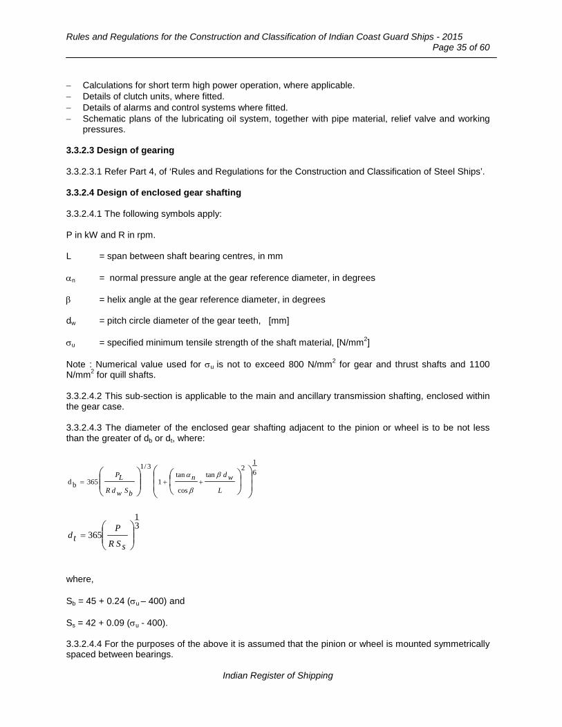
Rules and Regulations for the Construction and Classification of Indian Coast Guard Ships - 2015
Page 35 of 60
− Calculations for short term high power operation, where applicable. − Details of clutch units, where fitted. − Details of alarms and control systems where fitted. − Schematic plans of the lubricating oil system, together with pipe material, relief valve and working
pressures. 3.3.2.3 Design of gearing 3.3.2.3.1 Refer Part 4, of ‘Rules and Regulations for the Construction and Classification of Steel Ships’. 3.3.2.4 Design of enclosed gear shafting 3.3.2.4.1 The following symbols apply: P in kW and R in rpm. L = span between shaft bearing centres, in mm αn = normal pressure angle at the gear reference diameter, in degrees β = helix angle at the gear reference diameter, in degrees dw = pitch circle diameter of the gear teeth, [mm] σu = specified minimum tensile strength of the shaft material, [N/mm2] Note : Numerical value used for σu is not to exceed 800 N/mm2 for gear and thrust shafts and 1100 N/mm2 for quill shafts. 3.3.2.4.2 This sub-section is applicable to the main and ancillary transmission shafting, enclosed within the gear case. 3.3.2.4.3 The diameter of the enclosed gear shafting adjacent to the pinion or wheel is to be not less than the greater of db or dt, where:
61
2tan
cos
tan1
3/1
365bd
++=
L
wdn
bSwdR
LP β
β
α
31
365
=
sSR
Ptd
where, Sb = 45 + 0.24 (σu – 400) and Ss = 42 + 0.09 (σu - 400). 3.3.2.4.4 For the purposes of the above it is assumed that the pinion or wheel is mounted symmetrically spaced between bearings.
Indian Register of Shipping
Chapter 12 : Main and Auxiliary Machinery
Page 36 of 60 __________________________________________________________________________________
3.3.2.4.5 Outside a length equal to the required diameter at the pinion or wheel, the diameter may be reduced, if applicable, to that required for dt. 3.3.2.4.6 For bevel gear shafts, where a bearing is located adjacent to the gear section, the diameter of the shaft is to be not less than dt. Where a bearing is not located adjacent to the gear the diameter of the shaft will be specially considered. 3.3.2.4.7 The diameter of quill shaft (not axially constrained and subject only to external torsional loading) is to be not less than given by the following formula:
][mm3u R
400P x101 shaft quill ofDiameter
σ=
3.3.2.4.8 Where a shaft, located within the gear case, is subject to the main propulsion thrust the diameter at the collars of the shaft transmitting torque, or in way of the axial bearing where a roller bearing is used as a thrust bearing, is to be not less than 1.1 dt. For thrust bearings located outside the gear case see Section 2. 3.3.2.5 Gear wheels 3.3.2.5.1 In general, arrangements are to be made so that the interior structure of the wheel may be examined. Alternative proposals will be specially considered. 3.3.2.6 Gear cases 3.3.2.6.1 Gear cases and their supports are to be designed sufficiently stiff such that misalignment at the mesh due to movements of the external foundations and the thermal effects under all conditions of service do not disturb the overall tooth contact. 3.3.2.6.2 Inspection openings are to be provided at the peripheries of gear cases to enable the teeth of pinions and wheels to be readily examined. Where the construction of gear cases is such that sections of the structure cannot be readily be removed for inspection purposes, access openings of adequate size are also to be provided at the ends of the gear cases to permit examination of the structure of the wheels. Their attachment to the shafts is to be capable of being examined by removal of bearing caps or by equivalent means. 3.3.2.6.3 For gear cases fabricated by fusion welding the carbon content of the steels should generally not exceed 0.23 percent. Steels with higher carbon content may be approved subject to satisfactory results from weld procedure tests. 3.3.2.6.4 Gear cases are to be stress relieved upon completion of all welding. 3.3.2.6.5 Gear cases manufactured from material other than steel will be considered upon full details being submitted. 3.3.2.7 Alignment 3.3.2.7.1 Reduction gears with sleeve bearings, for main and auxiliary purposes are to be provided with means for checking the internal alignment of the various elements in the gear cases.
Indian Register of Shipping

Rules and Regulations for the Construction and Classification of Indian Coast Guard Ships - 2015
Page 37 of 60
3.3.2.7.2 In the case of separately mounted reduction gearing for main propulsion, means are to be provided by the gear manufacturer to enable the Surveyors to verify that no distortion of the gear case has taken place, when chocked and secured to its seating on board the ship. 3.3.2.8 Control and Monitoring 3.3.2.8.1 General 3.3.2.8.1.1 Control engineering systems are to be in accordance with Chapter 14. 3.3.2.8.1.2 All main and auxiliary gear units, intended for essential services, are to be provided with means of indicating the lubricating oil supply pressure. Audible and visual alarms are to be fitted to give warning of an appreciable reduction in pressure of the lubricating oil supply. These alarms are to be actuated from the outlet side of any restrictions, such as filters, coolers, etc. 3.3.2.8.2 Unattended machinery 3.3.2.8.2.1 Where the machinery is fitted with automatic or remote controls so that under normal operating conditions it does not require any manual intervention by the operators, gear units are to be provided with the alarms and safety arrangements required by 3.3.2.8.2.2 and Table 3.3.2.8.1. The sensors and circuits utilised for the second stage alarm and automatic shut down in Table 3.3.2.8.1 are to be independent of those required for the first stage alarm. For ships, less than 150 GT the alarms required by 3.3.2.8.2.1 are not applicable. 3.3.2.8.2.2 Where the gear unit is required to be provided with a standby pump, the standby pump is to start automatically if the discharge pressure from the working pump falls below a predetermined value.
Table 3.3.2.8.1 : Alarms and safeguards
Item Alarm Note Lubricating oil sump level
Low
Lubricating oil inlet pressure
1st Stage Low
Lubricating oil inlet pressure
2nd Stage Low
Automatic shutdown of engine
Lubricating oil inlet temperature
High
Thrust bearing temperature
High
Indian Register of Shipping

Chapter 12 : Main and Auxiliary Machinery
Page 38 of 60 __________________________________________________________________________________
3.3.2.9 Design of gearing 3.3.2.9.1 The gearing factors of safety for ships of less than 150 GT are to satisfy Table 3.3.2.9.1.
Table 3.3.2.9.1 : Factors of safety
SH min SF min Main propulsion gears single screw 1.25 1.50
Main propulsion gears multiple screw 1.20 1.45
3.3.2.9.2 These ships are to have gearing provided with an efficient lubricating oil pump, a cooler where necessary and a filter arrangement which can be cleaned. 3.3.2.10 Tests 3.3.2.10.1 Where castings are used for wheel centres, any radial slots in the periphery are to be fitted with permanent chocks before shrinking-on-the rim. 3.3.2.10.2 Where welding is employed in the construction of wheels and gear cases, the welding procedure is to be approved before work is commenced. For this purpose, welding procedure approval test are to be carried out with satisfactory results. Such tests are to be representative of the joint configuration and materials. All welds are to have a satisfactory surface finish and contour. Magnetic particle or liquid penetrant examination of all important welded joints is to be carried out. 3.3.2.10.3 Welded constructions are to be stress relief heat treated on completion of welding. 3.3.2.10.4 Bolted attachments within the gear case are to be secured by locking wire or equivalent means. 3.3.2.10.5 The machining accuracy (Q grade) of pinions and wheels is to be demonstrated. For this purpose records of measurements are to be available for review. 3.3.2.10.6 Magnetic particle or liquid penetrant testing is to be carried out on the teeth of all surface hardened forgings. This examination may also be requested on the finished machined teeth of through hardened gear forgings. 3.3.2.10.7 The manufacturer is to carry out an ultrasonic examination of all forgings where the finished diameter of the surfaces, where teeth will be cut, is in excess of 200 mm and is to provide IRS with a signed statement that such inspection has not revealed any significant internal defects. 3.3.2.10.8 On gear forgings where the teeth have been surface hardened, additional test pieces may be required to be processed with the forgings and subsequently sectioned to determine the depth of the hardened zone. These tests are to be carried out at the discretion of the Surveyor and for induction or carburised gearing the depth of the hardened zone is to be in accordance with the approved specification. For nitrided gearing, the full depth of the hardened zone, i.e. depth to core hardness, is to be not less than 0.5 mm and the hardness at a depth of 0.25 mm is to be not less than 500 Hv. 3.3.2.10.9 All rotating elements such as pinion and wheel shaft assemblies and coupling parts, are to be appropriately balanced.
Indian Register of Shipping

Rules and Regulations for the Construction and Classification of Indian Coast Guard Ships - 2015
Page 39 of 60
3.3.2.10.10 The permissible residual unbalance, U, is defined as follows:
3000formmg310.m60
U ≤= RR
3000formmg310.m24
U >= RR
where, m = mass of rotating element [kg] R = maximum service rev/min of the rotating element.
3.3.2.10.11 Where the size or geometry of a rotating element precludes measurement of the residual unbalance a full speed running test of the assembled gear unit at the manufacturer’s works will normally be required to demonstrate satisfactory operation. 3.3.2.10.12 Initially, meshing gears are to be carefully matched on the basis of the accuracy measurements taken. The alignment is to be demonstrated in the workshop by meshing in the gearbox without oil clearance in the bearings. Meshing is to be carried out with the gears locating in their light load positions and a load sufficient to overcome pinion weight and axial movement is to be imposed. 3.3.2.10.13 The gears are to be suitably coated to demonstrate the contact marking. The thickness of the coating to determine the contact marking is not to exceed 0.005 mm. The marking is to reflect the accuracy grade specified and end relief, crowning or helix correction, where these have been applied. 3.3.2.10.14 For gears without crowning or helix correction the marking is to be not less than shown in the following Table:
No load tooth contact marking ISO accuracy
grade Contact marking area
Q ≤ 5 50% b x 40% hw + 40% b x 20% hw Q ≥ 6 35% b x 40% hw + 35% b x 20% hw Notes: 1. Where b is face width and hw is the working tooth depth. 2. For spur gears the values of hw should be increased by a further
10%. 3.3.2.10.15 Where allowance has been given for end relief, crowning or helix correction, the normal shop meshing tests are to be supplemented by tooth alignment traces or other approved means to demonstrate the effectiveness of such modifications. 3.3.2.10.16 For gears with crowning or helix correction the marking is to correspond to the designed no load contact pattern. 3.3.2.10.17 A permanent record is to be made of the meshing contact for purpose of checking the alignment when installed on board the ship. 3.3.2.10.18 The full load tooth contact marking is to be not less than shown in the following Table:
Indian Register of Shipping

Chapter 12 : Main and Auxiliary Machinery
Page 40 of 60 __________________________________________________________________________________
No load tooth contact marking
ISO accuracy grade Contact marking area Q ≤ 5 60% b x 70% hw + 30% b x 50% hw Q ≥ 6 45% b x 60% hw + 35% b x 40% hw Notes: 3. Where b is face width and hw is the working tooth depth. 4. For spur gears the values of hw should be increased by a further
10%. 3.3.2.10.19 Where, due to the compactness of the gear unit, meshing tests of individual units cannot be verified visually, consideration may be given to the gear manufacturer providing suitable evidence that the design meshing condition has been attained on units of the same design. 3.3.2.10.20 The normal backlash between any pair of gears should not be less than:
]mm[1.090000
n.a+
α
where, αn = normal pressure angle, in degrees a = centre distance [mm].
Section 4
Propeller, Thruster, Water Jet System 4.1 Propeller 4.1.1 General Requirements 4.1.1.1 For design requirements refer to Part 4, Chapter 4, Section 7 of ‘Rules and Regulations for the Construction and Classification of Steel Ships’. 4.1.1.2 For propellers having a skew angle equal or greater than 50o in addition to the particulars detailed in 4.1.1.1 the following details are to be submitted:
a) Full blade section details at each radial station defined for manufacture. b) A detailed blade stress computation supported by the following hydrodynamic data for the
ahead mean wake condition and when absorbing full power:
i) Radial distribution of lift and drag coefficients, section inflow velocities and hydrodynamic pitch angles.
ii) Section pressure distributions.
Indian Register of Shipping
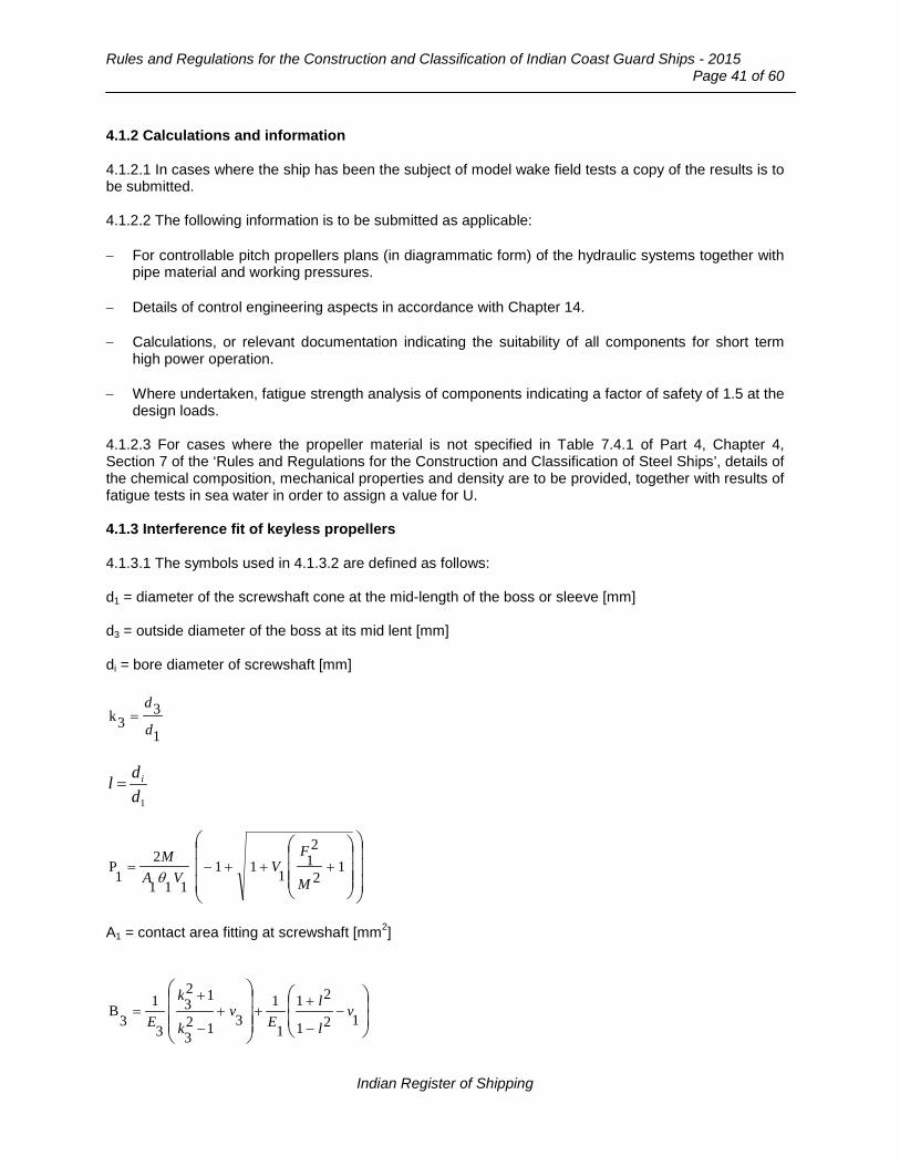
Rules and Regulations for the Construction and Classification of Indian Coast Guard Ships - 2015
Page 41 of 60
4.1.2 Calculations and information 4.1.2.1 In cases where the ship has been the subject of model wake field tests a copy of the results is to be submitted. 4.1.2.2 The following information is to be submitted as applicable: − For controllable pitch propellers plans (in diagrammatic form) of the hydraulic systems together with
pipe material and working pressures. − Details of control engineering aspects in accordance with Chapter 14. − Calculations, or relevant documentation indicating the suitability of all components for short term
high power operation. − Where undertaken, fatigue strength analysis of components indicating a factor of safety of 1.5 at the
design loads. 4.1.2.3 For cases where the propeller material is not specified in Table 7.4.1 of Part 4, Chapter 4, Section 7 of the ‘Rules and Regulations for the Construction and Classification of Steel Ships’, details of the chemical composition, mechanical properties and density are to be provided, together with results of fatigue tests in sea water in order to assign a value for U. 4.1.3 Interference fit of keyless propellers 4.1.3.1 The symbols used in 4.1.3.2 are defined as follows: d1 = diameter of the screwshaft cone at the mid-length of the boss or sleeve [mm] d3 = outside diameter of the boss at its mid lent [mm] di = bore diameter of screwshaft [mm]
1
33k
d
d=
1
ddl i=
+++−= 1
2
21
111111
21
PM
FV
VAMθ
A1 = contact area fitting at screwshaft [mm2]
−
−
+++
−
+= 121
21
1
1312
3
123
3
13
B vl
lE
vk
k
E
Indian Register of Shipping

Chapter 12 : Main and Auxiliary Machinery
Page 42 of 60 __________________________________________________________________________________
C = 0 for turbine installations or electric propulsion
onsinstallati engine oilfor speed service at the emean torqu
speed service at the torquevibratory =
E1 = modulus of elasticity of screwshaft material [N/mm2] E3 = modulus of elasticity of propeller material [N/mm2]
)1(2000
tF Cfd
Q+=
M = propeller thrust [N] Q = mean torque corresponding to P and R [Nm] T1 = temperature at time of fitting propeller on shaft oC
1
2
1
151.01V −=
θ
µ
α1 = coefficient of linear expansion of screwshaft material mm/mm/oC α3 = coefficient of linear expansion of propeller material mm/mm/oC θ1 = taper of the screwshaft cone but is not to exceed 1/15 on the diameter, i.e. θ1 ≤ 1/15 µ1 = coefficient of friction for fitting of boss assembly on shaft = 0.13 for oil injection method of fitting v1 = Poisson’s ratio for screwshaft material v3 = Poisson’s ratio for propeller material. 4.1.3.2 Where it is proposed to fit a keyless propeller by the oil shrink method, the pull up, δ on the screwshaft is to be not less than:
( ) ( )( ) mm][13513311
1d TBp −−+= ααθ
δ
The yield stress or 0.2 per cent proof stress, σ0 of the propeller material is to be not less than:
]2
[N/mm1
23
1433
)13(11
1
3
4.10
−
+−+=
k
kT
d
p
Bαα
δθσ
Indian Register of Shipping

Rules and Regulations for the Construction and Classification of Indian Coast Guard Ships - 2015
Page 43 of 60
where, δp = proposed pull-up at the fitting temperature. The start point load, W, to determine the actual pull up is to be not less than:
][)13(3
18120
1002.01A W NB
p
−++= αα
θ
4.1.4 Automatic and remote controls 4.1.4.1 Where controllable pitch propellers are fitted with automatic or remote controls so that under normal operating conditions they do not require any manual intervention by the operators, they are to be provided with the alarms and safety arrangements required by 4.1.4.2, 4.1.4.3 and Table 4.1.1. 4.1.4.2 For controllable pitch propellers for main propulsion, a standby or alternative power source of actuating medium for controlling the pitch of the propeller blades is to be provided. Automatic start of the standby pump supplying hydraulic power for pitch control is to be provided.
Table 4.1.1
Item Alarm Note Hydraulic system pressure Low - Hydraulic oil supply tank level Low - Hydraulic oil temperature High Where an oil cooler is fitted Power supply to the control system between the remote control station and hydraulic actuator
Failure Failure of any power supply to a control system is to operate an audible and visual alarm
Propulsion motor Overload See Chapter 14 4.1.4.3 For controllable pitch propellers, a shaft speed indicator and a pitch indicator which shows the degree of pitch as a measure of the propeller blade or actuator movement are to be provided at each station from which it is possible to control shaft speed or propeller pitch. 4.1.5 Requirements for ships with propellers not exceeding one metre in diameter 4.1.5.1 The materials and the scantlings need not comply with sections 4.1.1 to 4.1.4 4.1.5.2 Propellers for ships less than 150 GT and main engine power output not exceeding 500 [kW] are to be manufactured from materials in accordance with Part 2 at a works recognised for the quality of its casting and machining, and be free from defects. 4.1.5.3 Specific requirements for the piping systems are given in Chapter 11. 4.1.5.4 The alarm and monitoring arrangements and for controllable pitch propellers the safety arrangements and standby power sources, will be specially considered. 4.1.6 Alternative materials and design 4.1.6.1 Propellers made from materials not listed in Part 2 or of unusual form or design will be specially considered.
Indian Register of Shipping
Chapter 12 : Main and Auxiliary Machinery
Page 44 of 60 __________________________________________________________________________________
4.1.7 Tests 4.1.7.1 Castings are to be examined at the manufacturer’s works. 4.1.7.2 All finished propellers are to be examined for material defects and finish and measured for dimensional accuracy of diameter and pitch, Propeller repairs by welding, where proposed, are to be in accordance with the requirements of Part 2, Chapter 8, Section 3 of Rules and Regulations For Construction And Classification of Steel Ships. 4.1.7.3 The bedding of the propeller with the shaft is to be demonstrated. Sufficient time is to be allowed for the temperature of the components to equalize before bedding. Alternative means for demonstrating the bedding of the propeller will be considered. 4.1.7.4 Means are to be provided to indicate the relative axial position of the propeller boss on the shaft taper. 4.1.7.5 The components of controllable pitch propellers are also subject to material tests, as in the case of solid propellers. 4.1.7.6 Examination of all the major components including dimensional checks, hydraulic pressure testing of the hub and cone assembly and the oil distribution box, where fitted, together with a full shop trial of the completed controllable pitch propeller assembly, is to be carried out. 4.1.7.7 After verifying that the propeller and shaft are at the same temperature and the mating surfaces are clean and free from oil or grease, the propeller is to be fitted on the shaft under survey. The propeller nut is to be securely locked to the shaft. 4.1.7.8 Permanent reference marks are to be made on the propeller boss nut and shaft to indicate angular and axial positioning of the propeller. Care is to be taken in marking the inboard end of the shaft taper to minimize stress-raising effects. 4.1.7.9 The outside of the propeller boss is to be hard stamped with the following details: − For oil injection method of fitting, the start point load, in Newtons, and the axial pull-up to 0oC and
35oC in mm. − For the dry fitting method, the push-up load at 0oC and 35oC in Newtons. 4.1.7.10 A copy of the fitting curve relative to temperature and means for determining any subsequent movement of the propeller are to be placed on board. 4.1.7.11 The fit of the screwshaft cone to both the working and any spare propeller is to be carried out under survey. Generally, a satisfactory fit for keyed type propellers should show a light, overall marking of the cone surface with a tendency towards heavier marking in way of the larger diameter of the cone face. The final fit to cone should be made with the key in places.
Indian Register of Shipping

Rules and Regulations for the Construction and Classification of Indian Coast Guard Ships - 2015
Page 45 of 60
4.2 Thruster 4.2.1 General Requirements 4.2.1.1 Application 4.2.1.1.1 This sub-section is to be read in conjunction with the General Requirements for machinery. 4.2.1.1.2 This sub-section gives requirements for fixed or steerable thruster units (azimuth thrusters) which are used for propulsion and steering and also applies to transverse propulsion (tunnel) thrusters which are an aid to manoeuvring. 4.2.1.1.3 For determining the dimensions of main propulsion components power P is in kW and R in revolutions per minute of the component. 4.2.1.2 Redundancy 4.2.1.2.1 A minimum of two azimuth thruster units are to be provided where these form the sole means of propulsion. Where a single azimuth thruster installation is proposed, it will be subject to consideration, taking into account the proposed restricted area notation. 4.2.1.2.2 The failure of one azimuth thruster unit or its control system is not to render any other thruster inoperative. 4.2.1.3 Inclination of ship 4.2.1.3.1 Thruster units are to operate satisfactorily under the conditions as shown in Section 1. 4.2.2 Particulars to be submitted 4.2.2.1 Submission of information 4.2.2.1.1 At least three copies of the following plans are to be submitted. 4.2.2.1.2 Fixed/Azimuth propulsion thrusters a) A general arrangement sectional assembly plan showing all the connections of the torque
transmitting components from the prime mover to the propeller, together with the azimuthing mechanism and if a nozzle is provided, the nozzle ring structure and nozzle support struts.
b) Detailed and dimensional plans of the individual torque transmitting components. c) Schematic plans of lubricating and hydraulic systems, together with pipe material, relief valves and
working pressures. 4.2.2.1.3 Tunnel thrusters Structural assembly plan including connections to tunnel. 4.2.2.2 Calculations and specifications 4.2.2.2.1 At least three copies of the following information are to be submitted:
a) Thruster prime mover type and operational power/speed envelop. b) Rating and type of motor for the azimuthing mechanism (e.g. type hydraulic or electric).
Indian Register of Shipping

Chapter 12 : Main and Auxiliary Machinery
Page 46 of 60 __________________________________________________________________________________
c) Gearing calculations for the azimuthing mechanism which is to be designed to a recognised National/International Standard.
d) Bearing specifications. e) Details of control engineering aspects in accordance with Chapter 14. f) Calculations indicating suitability of components for short term high power operation, where
applicable. g) Where carried out in accordance with Section 1, a fatigue strength analysis of components
indicating a factor of safety of 1.5 at the design loads, based on a suitable fatigue failure criteria.
4.2.2.2.2 Tunnel thrusters Specification for materials of gears, shafts, couplings and propeller, stock and struts. 4.2.3 Materials 4.2.3.1 Azimuth thrusters 4.2.3.1.1 The materials used in the construction are to be manufactured and tested in accordance with Part 2. 4.2.4 Design and Construction 4.2.4.1 General 4.2.4.1.1 The arrangement of all types of thrusters is to be such that the ship can be manoeuvred in accordance with the design specifications. 4.2.4.1.2 The requirements associated with the structural and watertight integrity and the installation arrangement are to be in accordance with Chapter 7. 4.2.4.1.3 In addition to the requirements of this section reference is to be made to:
a) Main transmission gearing (Section 3.3). b) Main transmission shafting (Section 2). c) Propeller (Section 4.1). d) Torsional vibration (Part 4, Chapter 4, Section 8 of the ‘Rules and Regulations for the
Construction and Classification of Steel Ships’). e) Lateral vibration for shafting systems which include cardan shafts (Part 4, Chapter 4, Section 8
of the ‘Rules and Regulations for the Construction and Classification of Steel Ships’).
4.2.4.2 Azimuth thrusters 4.2.4.2.1 The following requirements are to be complied with:
a) The azimuthing mechanism is to be capable of a maximum rotational speed of not less than 1.5 rev/min.
b) Gearing for the azimuthing mechanism is to be designed to a recognised National Standard. c) Under dynamic operating conditions, the gear is to be considered for:
− Design maximum dynamic duty steering torque, − Variable loading, where applicable. A spectrum (duty) factor may be used. The load
spectrum value is to be derived using load measurements of similar units, where possible.
Indian Register of Shipping

Rules and Regulations for the Construction and Classification of Indian Coast Guard Ships - 2015
Page 47 of 60
d) Under a static duty (< 103 load cycles) steering torque, which should be not less than QR, as
defined in Part 3 of ‘Rules and Regulations for the Construction and Classification of Steel Ships’.
e) The following minimum factor of safety values are to be achieved:
• Surface Stress SHmin = 1.0 • Bending Stress SFmin = 1.5
f) For hydraulic pressure retaining parts and load bearing (See Chapter 7).
4.2.4.3 Azimuth thrusters with a nozzle 4.2.4.3.1 Where the propeller is contained within a nozzle, the equivalent rudder stock diameter in way of tiller, used in Chapter 7 is to be determined as follows:
[mm]3 rNA23)(Vx26.03ud +=
where, V = maximum service speed, in knots, which the ship is designed to maintain under thruster operation. AN = projected nozzle area, in m2, and is equal to the length of the nozzle multiplied by the mean external vertical height of the nozzle r = horizontal distance from the centreline of the steering tube to the centre of pressure, in metres.
The corresponding maximum turning moment, QR, is to be determined as follows:
[Nmm]3udx11.1RQ =
4.2.4.3.2 In addition to the requirements in Chapter 8 the scantlings of the nozzle stock or steering tube are to be such that the section modulus Z against transverse bending at any section x-x is not less than:
]3[cm410x2T42a2r2
NA43)(Vx1.73 Z ++=
where, a = dimension, in metres, as shown in Fig.4.2.4.3.2. T = maximum thrust of the thruster unit, in tonnes.
4.2.4.3.3 The scantlings of nozzle connections or struts will be specially considered. In the case of certain high powered ship, direct calculation may be required. 4.2.4.3.4 Where the propeller is not contained in a nozzle, the scantlings in way of the tiller will be subject to special consideration.
Indian Register of Shipping

Chapter 12 : Main and Auxiliary Machinery
Page 48 of 60 __________________________________________________________________________________
Fig. 4.2.4.3.2 : Azimuth thruster
4.2.5 Piping Systems 4.2.5.1 General 4.2.5.1.1 The piping system for azimuth thrusters is to comply with the general design requirements given in Chapter 11. 4.2.5.1.2 The specific requirements for lubricating / hydraulic oil systems and standby arrangements are given in Chapter 11. 4.2.5.2 Azimuth thruster 4.2.5.2.1 The hydraulic power operating systems for each azimuth thruster are to be provided with the following: a) Arrangements to maintain the cleanliness of the hydraulic fluid, taking into consideration the type
and design of the hydraulic system. b) A fixed storage tank having sufficient capacity to recharge at least one azimuth power actuating
system including the reservoir. The piping from the storage tank is to be permanent and arranged in such a manner as to allow recharging from within the thruster space.
4.2.5.2.2 Where the lubricating oil for the azimuth thrusters is circulated under pressure, provision is to be made for the efficient filtration of the oil. The filters are to be capable of being cleaned without stopping the thruster or reducing the supply of filtered oil.
X
a
X
Indian Register of Shipping

Rules and Regulations for the Construction and Classification of Indian Coast Guard Ships - 2015
Page 49 of 60
4.2.6 Control and Monitoring 4.2.6.1 General 4.2.6.1.1 Except where indicated in this section the control engineering systems are to be in accordance with Chapter 14. 4.2.6.1.2 Azimuthing control for azimuth thruster(s) and propeller pitch control for azimuth and/or tunnel thruster(s) are to be provided from the navigating bridge, the main machinery control station and locally. 4.2.6.1.3 Means are to be provided at the remote control station(s) to stop each azimuth or tunnel thruster unit. 4.2.6.2 Monitoring and alarms (not required for ships less than 150 GT). 4.2.6.2.1 Alarms and monitoring requirements are indicated in 4.2.6.2.2, 4.2.6.2.3 and Table 4.2.6.1. 4.2.6.2.2 An indication of the angular position of the azimuth thruster(s) and the propeller pitch position for azimuth and/or tunnel thruster(s) are to be provided at each station from which it is possible to control the direction of thrust or the pitch. 4.2.6.2.3 All alarms associated with thruster unit faults are to be indicated individually on the navigating bridge and in accordance with the alarm system specified by Chapter 14.
Table 4.2.6.1
Item Alarm Note Thruster, azimuth or tunnel Indicators, see 4.2.6.2.2 Azimuthing motor Power failure,
single phase Also running indication on bridge and at machinery control station
Propeller pitch motor Power failure Also running indication on bridge and at machinery control station
Propulsion motor Overload, power failure
Also running indication on bridge and at machinery control station
Control system Failure Hydraulic oil supply tank level Low Hydraulic oil system pressure Low Hydraulic oil system temperature High Where oil cooler is fitted Hydraulic oil filters differential pressure
High Where oil filters are fitted
Lubricating oil supply pressure Low If separate forced lubrication
Indian Register of Shipping
Chapter 12 : Main and Auxiliary Machinery
Page 50 of 60 __________________________________________________________________________________
4.2.7 Electrical Systems 4.2.7.1 General 4.2.7.1.1 The electrical installation is to be designed, constructed and installed in accordance with the requirements of Chapter 13. 4.2.7.2 Emergency power for steering systems and drives 4.2.7.2.1 For high speed ship, in the event of total power failure, either:
a) emergency power for steering systems / drives is to be restored automatically within five seconds. To achieve this an interim fast acting system may be required to come into operation until such time as the auxiliary / emergency power source comes on line. (Note : starting arrangements are to comply with the requirements relating to starting arrangements of emergency generators),
OR
b) means are to be provided to bring the ship to a safe condition.
4.2.7.3 Circuits 4.2.7.3.1 Azimuth thruster auxiliaries and controls are to be served by individual circuits. Services that are duplicated are to be separated throughout their length as widely as is practicable and without the use of common feeders, transformers, converters, protective devices or control circuits. 4.2.8 Design and installation 4.2.8.1. Tunnel thrusters on ship less than 150 GT which are not essential for steering and manoeurving do not have to comply with the design requirements of this chapter. 4.2.8..2 The installation of such thrusters is to be such as to maintain the structural and watertight integrity of the ship. 4.2.9 Tests 4.2.9.1 Azimuth thrusters 4.2.9.1.1 The performance specified for the ship is to be demonstrated. 4.2.9.1.2 The actual values of steering torque are to be verified during sea trials to confirm that the design maximum dynamic duty torque has not been exceeded. 4.2.9.2 Tunnel thrusters 4.2.9.2.1 It is to be demonstrated that the thruster unit meets the specified performance.
Indian Register of Shipping
Rules and Regulations for the Construction and Classification of Indian Coast Guard Ships - 2015
Page 51 of 60
4.3 Water Jet System 4.3.1 General Requirements 4.3.1.1 Application 4.3.1.1.1 This chapter is to be read in conjunction with the General Requirements for Machinery in Section 1. 4.3.1.1.2 This chapter gives requirements for fixed or steerable water jet propulsion systems which are integral with the ship’s hull structure and form the main means of propulsion. The arrangements of water jet units for other purposes will be considered in relation to their intended duty. 4.3.1.1.3 A water jet propulsion unit is defined as a machine which takes in water, by means of a suitable inlet and ducting system and accelerates the mass of water using an impeller and nozzle to form a jet propulsion system. 4.3.1.2 Redundancy 4.3.1.2.1 In general a minimum of two water jet units are to be provided where these form the sole means of propulsion. 4.3.1.2.2 The failure of one water jet unit or its control system is not to render any other water to unit inoperative. 4.3.1.2.3 Where a single water jet installation is proposed, it will be subject to special consideration, taking into account the proposed restricted area notation. A formal risk assessment will be required in these cases. 4.3.2 Particulars to be submitted 4.3.2.1 Plans 4.3.2.1.1 General arrangement plans showing details of the following:
a) Shafting assembly indicating bearing positions; b) Steering assembly; c) Reversing assembly; d) Longitudinal section of the complete water jet unit.
4.3.2.1.2 Details dimension plans indicating scantlings and materials of construction of the following:
a) Arrangement of the system, including intended method of attachment to the hull and building in, geometry of tunnel, shell openings, method of stiffening, reinforcement, etc.
b) All torque transmitting components, including impeller and also stator if fitted. c) Steering components, together with a description and line diagram of the control circuit. This
includes steerable exit water jet nozzles where fitted. d) Components of retractable buckets where these are used for providing astern thrust. e) The bearing or bearings absorbing the thrust and supporting the impeller, together with the
method of lubrication.
Indian Register of Shipping

Chapter 12 : Main and Auxiliary Machinery
Page 52 of 60 __________________________________________________________________________________
f) Shaft sealing arrangements. g) Details of any shafting support or guide vanes used in the water jet system.
4.3.2.1.3 Schematic plans of the lubricating and hydraulic systems, together with pipe material, relief valves and working pressures. 4.3.2.2 Calculations and information 4.3.2.2.1 Details of the power/speed range of operation indicating the maximum continuous torque together with flow rate and thrust. 4.3.2.2.2 Strength calculations, using the maximum continuous torque rating and the most ‘onerous’ operating condition, including short term high power operation, as a design case including the effects of mean and fluctuating loads, residual stresses and stress raisers, for:
a) Impeller and, if fitted, the stator and any bolting arrangements. b) Shaft supports and guide vanes if fitted.
In the absence of precise information, the fluctuating stress may be assumed to be 15 percent of the maximum stress. As an alternative to fatigue strength calculation results of an approved measurement programme may be submitted. In all cases, a factor of safety of at least 1.5 is to be demonstrated for the maximum continuous rating condition.
c) Detailed weld specification where an impeller has welded blades. Welds are to be full
penetration type or of equivalent strength. d) Steering components, including lugs of steerable nozzles where fitted. e) Retractable buckets and associated mechanism, which are used to provide astern thrust. A
calculation of the hydrodynamic transient loads is to be made for each design and is to include the full ahead to full astern condition. The calculation procedure used is to be supported, where possible, with appropriate full scale or model test data or satisfactory service experience to validate the design method.
4.3.2.2.3 Details of the Designer’s loadings and positions of application in the hull are to be submitted and should include maximum applied thrust, moments and tunnel pressures. The tunnel strength and supporting structure are to be examined by direct calculation procedures and submitted for consideration. 4.3.2.2.4 Calculations, or relevant documentation indicating the suitability of all components for short term high power operation, where applicable. 4.3.2.2.5 Where it is proposed to use composite (non-metallic) shafts, details of materials, resin, lay-up procedure and documentary evidence of fatigue endurance strength. 4.3.2.2.6 Torsional vibration calculations of the complete dynamic system in accordance with Part 4, Chapter 4, Section 8 of the ‘Rules and Regulations for the Construction and Classification of Steel Ships’, together with a torsional schematic of the water jet unit. 4.3.2.2.7 Shaft whirling calculations where required by Part 4, Chapter 4, Section 8 of the ‘Rules and Regulations for the Construction and Classification of Steel Ships’. 4.3.2.2.8 Details of control engineering aspects are to be in accordance with Chapter 14.
Indian Register of Shipping

Rules and Regulations for the Construction and Classification of Indian Coast Guard Ships - 2015
Page 53 of 60
4.3.3 Materials 4.3.3.1 General 4.3.3.1.1 The materials used in the construction are to be manufactured and tested in accordance with Part 2. 4.3.3.1.2 Machinery components are to be of steel or other approved non-ferrous metals suitable for the intended environment. 4.3.3.2 Fibre reinforced plastic 4.3.3.2.1 Fibre Reinforced Plastic materials (FRP) may be used for certain components, provided that they are of adequate strength and comply with the requirements of Chapter 6. 4.3.4 Design and Construction 4.3.4.1 Shaftline 4.3.4.1.1 The diameter of the shafting is to comply with Section 2. For calculation purposes the shaft carrying the impeller is to be taken as equivalent to a screwshaft. 4.3.4.1.2 Where it is proposed to use carbon or carbon manganese steel shafts which may be in contact with seawater, these are to be protected. Full details of the means of protection are to be submitted. 4.3.4.1.3 Where lengths of shafts are joined using couplings of the shrunk element type, full particulars of the method of achieving the grip force are to be forwarded for consideration. A factor of safety against slippage of 2.0, based upon mean plus vibratory torque, is to be achieved for couplings located inboard, and likewise 2.5 for couplings which are located outboard. 4.3.4.1.4 For the interference fit of keyless impellers the requirements of Section 4 are to be applied. 4.3.4.2 Shaft support system and guide vanes 4.3.4.2.1 In cases where the shaft requires support from the tunnel walls ahead of the impeller, or, alternatively, where guide vanes are required to assist the flow around a bend in the ducting system, the supports or guide vanes are to be aligned to the flow and have suitably rounded leading and trailing edges or be of an aero-foil section. 4.3.4.2.2 Fatigue strength calculations of supports or guide vanes are to be submitted and are to include the effects of mean and fluctuating loads, residual stresses and stress raisers, in general, the fillet radius should not be less than the maximum thickness at that location. Smaller radii may be considered for which the results of an approved measurement programme are to be submitted. In all cases, a factor of safety of at least 1.5 is to be demonstrated for the designed operating conditions. 4.3.4.2.3 A facility for the inspection of the supports or guide vanes is to be provided which will allow either direct visual or boroscope inspection of these components. 4.3.4.3 Impeller 4.3.4.3.1 In general, the fillet radius should not be less than the maximum thickness at that location. Composite radiused fillets or elliptical fillets which provide an improved stress concentration factor are acceptable and are to be preferred.
Indian Register of Shipping

Chapter 12 : Main and Auxiliary Machinery
Page 54 of 60 __________________________________________________________________________________
4.3.4.3.2 Where an impeller has bolted on blades, consideration is also to be given to the distribution of stress in the palms of the blade and in the hub and bolting arrangements. 4.3.4.3.3 The blades are to be provided with hydro-dynamically faired leading and trailing edges which may be either of simple radius or of a more complex aerofoil edge form. The tip clearance, whilst being kept to a minimum for hydrodynamic purposes must be sufficient to allow for any transient vibrational behaviour, axial shaft movement or differential thermal expansion. 4.3.4.3.4 A calculation of the blade natural frequency for the impeller blades is to be undertaken. As such the natural frequency should be shown to lie outside any expected excitation frequencies within a speed range of 30 percent below to 10 percent above the maximum impeller speed. Deviations from these limits will be considered. 4.3.4.3.5 A facility for the in service inspection of the impeller and sector (if fitted) blades is to be provided which will allow for either a direct visual or boroscope inspection of the complete blade surfaces. 4.3.4.4 Stator 4.3.4.4.1 The stator blades, where fitted, are to be designed to be capable of withstanding the combined hydrodynamic and mechanical loads (including any loads transmitted via shaft bearings) developed by the unit and reacted through the blades when the impeller is absorbing full power and the vessel is either free running or undergoing a crash stop manoeuvre, whichever imposes the greater loading on the blades. 4.3.4.4.2 In general, the fillet radius should not be less than the maximum thickness at that location. Composite radiused fillets or elliptical fillets which provide improved stress concentration factors are acceptable and are to be preferred. 4.3.4.4.3 If the stator ring is a composite assembly then consideration is also to be given to the distribution of stress in the various adjacent members. 4.3.4.4.4 A calculation of the relative blade passing frequency between the rotor and stator blades is to be carried out and it is to be demonstrated that this does not coincide with the natural frequency of the stator blades over a speed range of 30 percent below to 10 percent above maximum impeller speed. Similarly this condition is to be demonstrated for the manoeuvring speeds. 4.3.4.4.5 The stator blades are to be provided with hydro-dynamically faired leading edges which may have either a simple radius or a more complex aerofoil edge form. 4.3.4.4.6 Where the stator blading assembly forms part of the nozzle, the requirements of 4.3.4.6 must be considered in association with those for the stator assembly. 4.3.4.5 Tunnel and securing arrangements 4.3.4.5.1 The tunnel is to be adequately supported, framed and fully integrated into the hull structure. 4.3.4.5.2 The tunnel and supporting structure scantlings are to be not less than the Rule requirements for the surrounding structure. The strength of the hull structure in way of tunnels is to be maintained. The structure is to be adequately reinforced and compensated as necessary. All openings are to be suitably reinforced and have radiused corners. 4.3.4.5.3 Consideration should be given to providing the inlet to the tunnel with a suitable guard to prevent the ingress of large objects into the roto-dynamic machinery. The dimensions of this guard must
Indian Register of Shipping

Rules and Regulations for the Construction and Classification of Indian Coast Guard Ships - 2015
Page 55 of 60
strike a balance between undue efficiency loss due to flow restriction and viscous losses, the size of object allowed to pass and susceptibility to clog with weed and other flow restricting matter. 4.3.4.5.4 The inlet profile of the tunnel is to be designed so as to provide a smooth uptake of the water over the range of vessel operating trims and avoid significant separating of the flow into the rotating machinery. 4.3.4.5.5 Design consideration is to take account of pressures which could develop as a result of a duct blockage, and to the axial location of rotating parts. 4.3.4.6 Nozzle and reversing bucket 4.3.4.6.1 Nozzles can be either of a fixed or steerable form. The design of the nozzle must fully take into account the change in pressure distribution along its inner surface together with the other mechanical loads (e.g. stator assembly loads) and transient loads caused by the flow directing attachments and bucket loads which may be reacted through the body of the nozzle. In this analysis the changes to the pressure distribution caused by transient manoeuvres are to be considered. 4.3.4.6.2 Consideration is to be given to all transient loads the bucket is likely to experience from manoeuvring and the sea conditions. 4.3.4.6.3 The bucket is to be given reasonable mechanical protection from other impact damage such as collision with harbour walls, other vessels, buoys, etc. 4.3.4.7 Steering system 4.3.4.7.1 In general the steering systems are to comply with the requirements of Chapter 7. 4.3.4.7.2 In addition to the requirements of Chapter 7 the steering mechanism is to be capable of turning the nozzle unit at not less than 1.5 rev/min. 4.3.5 Piping Systems 4.3.5.1 General 4.3.5.1.1 The piping systems for a water jet unit are to comply with the general requirements of Chapter 11, Section 1. 4.3.5.1.2 The specific requirements for lubricating hydraulic oil systems and standby arrangements are given in Chapter 11. Requirements for steering hydraulic systems are given in Chapter 7. 4.3.5.2 Hydraulic power systems 4.3.5.2.1 The hydraulic power operating systems for each water jet unit are to be provided with the following:
a) Arrangements to maintain the cleanliness of the hydraulic fluid, taking into consideration the type and design of the hydraulic system.
b) A fixed storage tank having sufficient capacity to recharge at least one water jet power actuating
system including the reservoir.
Indian Register of Shipping

Chapter 12 : Main and Auxiliary Machinery
Page 56 of 60 __________________________________________________________________________________
4.3.6 Control and monitoring 4.3.6.1 General 4.3.6.1.1 For water jets used as the only means of propulsion, a standby or alternative power source of actuating medium for controlling the angular position and/or the reversing angle is to be provided. Automatic start of the standby pump supplying hydraulic power for steering and reserving is to be provided. 4.3.6.1.2 Means are to be provided at each station to stop each water jet. 4.3.6.2 Monitoring and alarms 4.3.6.2.1 Alarms and monitoring requirements are indicated in 4.3.6.2.2 to 4.3.6.2.4 and Table 4.3.6.2.
Table 4.3.6.2
Item Alarm Note Hydraulic system pressure Low - Hydraulic oil supply tank level Low - Hydraulic oil temperature High Where an oil
cooler is fitted Hydraulic system flow Low - Lubricating oil pressure Low - Control system Fault - Control system power supply Failure -
4.3.6.2.2 An indication of the angular position of the nozzle is to be provided at each station from which it is possible to control the direction of thrust. 4.3.6.2.3 An indication of both the required and actual reversing bucket position is to be provided at each station from which it is possible to control the reversal of thrust. 4.3.6.2.4 All alarms associated with water jet unit faults are to be indicated individually at the controls stations and in accordance with the alarm system specified by Chapter 14. 4.3.7 Electrical Systems 4.3.7.1 Distribution arrangements 4.3.7.1.1 Water jet auxiliaries and controls are to be served by individual circuits. Services that are duplicated are to be separated throughout their length as widely as is practicable and without the use of common feeders, transformers, convertors, protective devices or control circuits. 4.3.8 Tests 4.3.8.1 The following components are to be inspected at the manufacturer’s works: − steering nozzle, − reverse bucket, − stator impeller − integral bearing.
Indian Register of Shipping

Rules and Regulations for the Construction and Classification of Indian Coast Guard Ships - 2015
Page 57 of 60
4.3.8.2 Welded components are to comply with the requirement of Chapter 12 and be subject to stress relief heat treatment upon completion. Where an impeller has welded blades, non-destructive testing is to be carried out to an approved procedure. 4.3.8.3 Testing of the first installation of a new type of water jet unit is required and is to demonstrate the adequacy of the steering and reversing mechanisms during the most arduous manoeuvres. 4.3.8.4 Upon completion, the impeller assembly is to be suitably balanced in accordance with ISO 940 Grade G6.3 or an equivalent standard.
Section 5
Pressure Vessels
5.1 Application 5.1.1 The requirements of this chapter are applicable to fusion welded pressure vessels and their mountings and fittings, where plans have to be submitted in accordance with 5.2. 5.1.2 Seamless pressure vessels are to be manufactured in accordance with the requirements of Part 2 of ‘Rules and Regulations for the Construction and Classification of Steel Ships’. 5.1.3 Steam raising plant and associated pressure vessels should be designed and constructed in accordance with Part 4, Chapter 5 of ‘Rules and Regulations for the Construction and Classification of Steel Ships’. 5.2 Details to be submitted 5.2.1 Plans of pressure vessels are to be submitted in triplicate for consideration where all the conditions in (a) or (b) are satisfied:
a) The vessel contains vapours or gases, e.g. air receivers, hydrophore or similar vessels and gaseous CO2 vessels for fire fighting and
pV > 600 p > 1 V > 100 Where, V = volume (litres) of gas or vapour space. p = design pressure (bar)
b) The vessel contains liquefied gases for fire fighting, or flammable liquids, and
p > 7 V > 100 Where, V = volume (litres) p = design pressure (bar)
Indian Register of Shipping
Chapter 12 : Main and Auxiliary Machinery
Page 58 of 60 __________________________________________________________________________________
5.3 Materials 5.3.1 Materials used in the construction are to be manufactured and tested in accordance with the requirements of Part 2. 5.3.2 Where it is proposed to use materials other than those specified in Part 2, details of the chemical compositions, heat treatment and mechanical properties are to be submitted for approval. In such cases, the values of the mechanical properties used for deriving the allowable stress are to be subject to agreement by IRS. 5.4 Design pressure 5.4.1 The design pressure is the maximum permissible working pressure and is to be not less than the highest set pressure of any safety valve. 5.5 Metal temperature 5.5.1 The metal temperature, T, used to evaluate the allowable stress, σ, is to be taken as the actual metal temperature expected under operating conditions for the pressure part concerned, and is to be stated by the manufacturer when plans of the pressure parts are submitted for consideration. 5.5.2 For fusion welded pressure vessels the minimum design temperature, T, is not to be less than 50oC. 5.6 Design and construction 5.6.1 Refer Part 4, Chapter 5 of ‘Rules and Regulations for the Construction and Classification of Steel Ships’. 5.7 Mountings and Fittings for Pressure Vessels 5.7.1 General 5.7.1.1 Each pressure vessel or system is to be fitted with a stop valve situated as close as possible to the shell. 5.7.1.2 Adequate arrangements are to be provided to prevent over-pressure of any part of a pressure vessel which can be isolated. Pressure gauges are to be fitted in positions where they can be easily read. 5.7.1.3 Adequate arrangements are to be provided for draining and venting the separate parts of each pressure vessel. 5.7.2 Receivers containing pressurized gases 5.7.2.1 Each air receiver is to be fitted with a drain arrangement at its lowest part, permitting oil and water to be blown out. 5.7.2.2 Each receiver which can be isolated from a relief valve is to be provided with a suitable fusible plug to discharge the contents in case of fire. The melting point of the fusible plug is to be approximately 150oC. See also below.
Indian Register of Shipping

Rules and Regulations for the Construction and Classification of Indian Coast Guard Ships - 2015
Page 59 of 60
5.7.2.3.Where a fixed system utilizing fire extinguishing gas is fitted, to protect a machinery space containing an air receiver(s), fitted with a fusible plug, it is recommended that the discharge from the fusible plug be piped to the open deck. 5.7.2.4 Receivers used for the storage of air for the control of remotely operated valves are to be fitted with relief valves and not fusible plugs. 5.8 Hydraulic tests 5.8.1 Fusion welded pressure vessels 5.8.1.1.Fusion welded pressure vessels are to be tested on completion to a pressure, pT, determined by the following formula, without showing signs of weakness or defect:
but in no case is to exceed
where, p = design pressure in bar pT = test pressure, in bar t = nominal thickness of shell as indicated on the plan [mm] σT = allowable stress at design temperature [N/mm2] σ50 = allowable stress at 50oC [N/mm2].
5.8.2 Mountings 5.8.2.1 Mountings are to be subjected to a hydraulic test of twice the approved design pressure. 5.9 Fibre Reinforced Plastics Pressure Vessels 5.9.1 General 5.9.1.1 Pressure vessels may be constructed in fibre reinforced plastics provided the manufacturer is competent and suitably equipped for this purpose. 5.9.1.2 Pressure vessels are to be of standard design whose suitability has been established by fatigue and burst tests on a prototype. 5.9.2 Prototype testing 5.9.2.1 For the fatigue test the pressure shall be cycled from atmospheric to design pressure 100 000 times at the design temperature. 5.9.2.2 For the burst test the minimum bursting pressure shall be six times the design pressure.
p0.75)-(tt 1.5
p)75.0t(
t3.1pT
50T −σ
σ=
Indian Register of Shipping
Chapter 12 : Main and Auxiliary Machinery
Page 60 of 60 __________________________________________________________________________________
5.9.3 Production hydraulic test 5.9.3.1 Vessels subject to internal pressure shall be hydraulically tested to not less than 1.5 times the design pressure. 5.10 Requirements for Ships of less than 150 GT 5.10.1 Fibre reinforced plastics pressure vessels 5.10.1.1 Fibre reinforced plastics pressure vessels, where the product of the design pressure in bar and volume in litres exceeds 600, are not to be situated in machinery spaces or high risk areas on ship less than 150 GT. 5.10.1.2 Small fibre reinforced plastics pressure vessels will receive special consideration in relation to their intended duty and service conditions.
End Of Chapter
Indian Register of Shipping

Rules and Regulations for the Construction and Classification of Indian Coast Guard Ships – 2015
Page 1 of 5
Chapter 13
Electrical Installations
Contents Section
1 General Requirements 2 Requirements for Ships less than 500 GT
Section 1
General Requirements
1.1 General 1.1.1 All ships less than 500 tons GT are to meet the requirements of Section 2. 1.1.2 For ships of more than 500 tons GT , the requirements given in Part 4, Chapter 8 of the ‘Rules and Regulations for the Construction and Classification of Steel Ships’ are to be applied, in general.
Section 2
Requirements for Ships less than 500 GT
2.1 General requirements 2.1.1 The requirements of this section are applicable to the electrical installations in small ships as defined in 1.1.1 above, where the supply voltage does not exceed 440 volts ac or dc. 2.1.2 Alternative arrangements will be given special consideration. 2.2 Plans 2.2.1 The following plans and details for electrical installation are to be submitted in triplicate for approval. 2.2.2 Single line diagram of main power and lighting systems which is to include:
a) rating of machines; transformers; batteries and semi-conductor converters; b) all feeders connected to the main switchboard; c) section boards and distribution boards; d) insulation type, size and current loadings of cables; e) make, type and rating of circuit breakers and fuses.
Indian Register of Shipping

Chapter 13 : Electrical Installations
Page 2 of 5 __________________________________________________________________________________
2.2.3 Simplified diagrams of generator circuits and feeder-circuits showing:
a) protective devices; b) instrumentation and control devices; c) preference tripping; d) earth fault indication/protection.
2.2.4 Calculations of prospective short circuit current of main busbars and secondary side of transformers. (Additionally load schedule is to be submitted for information.) 2.2.5 Details of electrically operated personnel safety systems which are to include single line diagrams and a general arrangement plan of the vessel showing location and cable routes of:
a) fire detection, alarm and extinction systems; b) internal communication and alarm systems.
2.3 Trials 2.3.1 The installation is to be inspected and tested by the Surveyors, in accordance with the requirements of Part 4, Ch 8, Sec 13 of Rules and Regulations for the construction and classification of Steel Ships, as appropriate, and is to be to their satisfaction. 2.4 Addition or alterations 2.4.1 No addition, temporary or permanent, is to be made to the approved load of an existing installation until it has been ascertained that the current carrying capacity and the condition of the existing equipment including cables and switchgear are adequate for the increased load. 2.4.2 Plans are to be submitted for consideration and the alterations or additions are to be carried out under the survey and to the satisfaction of the Surveyors. 2.5 Location and construction of equipment 2.5.1 Electrical equipment is to be accessibly placed, clear of flammable material in well ventilated, adequately lighted spaces, in which flammable gases cannot accumulate and where it is not exposed to risk of mechanical damage or damage from water, steam or oil. Where necessarily exposed to such risks, the equipment is to be suitably constructed or enclosed. Equipment is to be accessible for maintenance. 2.5.2 Insulating materials and insulated windings are to be flame retardant and resistant to tracking, moisture, sea air and oil vapour unless special precautions are taken to protect them. 2.5.3 Securing arrangements used in connection with current carrying parts are to be effectively locked. 2.5.4 The operation of all electrical equipment is to be satisfactory under such conditions of vibrations, movements and shock as may arise in normal practice. 2.5.5 The design and installation of electrical equipment is to be such that the risk of fire due to its failure is minimized. It is, as a minimum, to comply with a National or International Standard revised where necessary for ambient conditions. Equipment is to be tested at the manufacturer’s works and a certificate of tests issued by the manufacturer.
Indian Register of Shipping
Rules and Regulations for the Construction and Classification of Indian Coast Guard Ships – 2015
Page 3 of 5
2.6 Systems of distribution 2.6.1 The following systems of generation and distribution are acceptable:
a) d.c., two-wire; b) a.c., single-phase, two-wire; c) a.c., three-phase, three-wire neutral insulated d) three-phase, four-wire with neutral solidly earthed but without hull return.
2.6.2 The arrangement of the sources of electrical power, generators or batteries, is to be such that a casualty in any one space does not result in loss of electrical power to circuits serving any safety, essential lighting and communication equipment. Any batteries provided for this duty are to be rated for at least 12 hours. 2.6.3 A device(s) is to be installed for every insulated distribution system, whether primary or secondary, for power, heating and lighting circuits to continuously monitor the insulation level to earth. 2.7 Earthing 2.7.1 Unless specifically exempted in 2.7.2 all accessible metal of the electric installation, other than current carrying accessible parts should be earthed. 2.7.2 The following parts may be exempted from the requirements of 2.7.1:
a) lamp-caps, where suitably shrouded; b) shades, reflectors and guards supported on lamp-holders or light fittings constructed of, or
shrouded in, non-conducting material; c) metal parts on, or screws in or through, non-conducting materials, which are separated by such
material from current-carrying parts and from earthed non-current carrying parts in such a way that in normal use they cannot become live or come into contact with earthed parts;
d) apparatus which is constructed in accordance with the principle of double insulation; e) bearing housings which are insulated in order to prevent circulation of current in the bearings; f) clips for fluorescent lamps; g) cable clips and short lengths of pipes for cable protection; h) apparatus supplied at a voltage not exceeding 55 V direct current or 55 V, root mean square,
between conductors, or between any conductor and earth in a circuit isolated from the supply. Autotransformers are not to be used for the purpose of achieving the alternating current voltage;
i) apparatus or parts of apparatus which although not shrouded in insulating material is nevertheless otherwise so guarded that it cannot be touched and cannot come in contact with exposed metal.
2.7.3 With wood and other non metallic hull constructions earthing connections are to be made to the general frame, engine, bed plate and earthing plate. Earthing connections are not to be made to hull sheathing, skin, fittings or plumbing. 2.8 Protection 2.8.1 Installations are to be protected against over-currents including short circuits. The tripping/fault clearance times of protective devices are to provide complete and co-ordinated protection to ensure:
a) availability of services not affected by the faulty circuit; b) elimination of the fault to reduce damage to the system and hazard of fire.
Indian Register of Shipping
Chapter 13 : Electrical Installations
Page 4 of 5 __________________________________________________________________________________
2.8.2 Short circuit protection and a means of complete isolation is to be provided for each source of power. 2.8.3 Protection for battery circuits is to be provided at a position external and adjacent to the battery compartments; batteries used solely for engine starting may be provided with only a means of isolation. 2.8.4 Short circuit and overload protection together with a means of isolation is to be provided in each non-earthed outgoing circuit of the main switchboard and each distribution board. 2.8.5 Each final sub-circuit is to be provided with short circuit protection and a means of isolation in each non-earthed line. 2.8.6 Lighting circuits are to be supplied by circuits separate from those for power. 2.8.7 Control circuits for engine monitoring and other services are to be provided with short circuit protection. 2.8.8 Protective devices are not to be fitted in any earthed line of a distribution system. 2.8.9 Circuit breakers and fuses are to have a certified fault rating adequate for the installation and are to comply with a National or International Standard. 2.9 Quality of power supplies 2.9.1 Unless specified otherwise electrical equipment, other than that supplied by battery systems, is to operate satisfactorily with the following simultaneous variations, from their nominal value, when measured at the consumer input terminals:
a) Voltage: Permanent variations + 6%, -10% Transient recovery +20%, -15% Recovery time 1.5 seconds.
b) Frequency:
Permanent variations ±5% transient Variation ±10% Recovery time 5 seconds.
2.9.2 Generator voltage regulators and engine governors are to be such as to ensure that the above supply variations are not exceeded. 2.10 Generators 2.10.1 The number and rating of generators is to be in accordance with 2.10.2 to 2.10.4. 2.10.2 The number and rating of electrical generators are to be sufficient to provide for normal seagoing loads even when one generator is out of action. 2.10.3 If generators are intended to operate in parallel there is to be appropriate protection and synchronizing equipment. 2.10.4 The generator(s) are to be sufficient to supply the normal loads.
Indian Register of Shipping
Rules and Regulations for the Construction and Classification of Indian Coast Guard Ships – 2015
Page 5 of 5
2.11 Cables 2.11.1 Cables and cable installations are to be in accordance with the requirements of Part 4, Chapter 8, Section 3 of the IRS Rules for Construction and Classification of Steel Ships. 2.12 Batteries 2.12.1 Batteries and battery installations are to be in accordance with the requirements of Part 4, Chapter 8, Section 7 of the IRS Rules for Construction and Classification of Steel Ships. 2.13 Lightning conductors 2.13.1 In composite vessels fitted with wooden masts, the lightning conductors are to be composed of continuous copper tape and/or rope, having a cross sectional area not less than 100 [mm2] which are to be riveted with copper rivets or fastened with copper clamps to a suitable copper spike not less than 13 [mm] in diameter, projecting at least 150 [mm] above the top of the mast. Where tape is used the lower end of the tape is to terminate at the point at which the shrouds leave the mast, and is to be securely clamped to a copper rope of not less than 13 [mm] diameter. This copper rope is to be lead down the shrouds and is to be securely clamped to a copper plate not less than 0.2 [m2] in area, fixed well below the light waterline and attached to the ship’s side in such a manner that it is to be immersed under all conditions of heel. 2.13.2 In composite vessels fitted with steel masts, each mast is to be connected to a copper plate in accordance with 2.13.1, the copper rope being securely attached to and in good electrical contact with the mast at or above the point at which the shrouds leave the mast. 2.13.3 In steel vessels fitted with wooden masts, the lightning conductors are to be composed of copper tape or rope terminating in a spike, as set forth in 2.13.1. At the lower end this copper tape or rope is to be securely clamped to the nearest metal forming part of the hull of the ship. 2.13.4 Lightning conductors are to be run as straight as possible and sharp bends in the conductors are to be avoided. All clamps used are to be of brass or copper, preferably of the serrated contact type and efficiently locked. No connection is to be dependent on a soldered joint. 2.13.5 The resistance of the lightning conductor, measured between the mast head and the position on the earth plate or hull to which the lightning conductor is earthed, is not to exceed 0.02 [ohms].
End of Chapter
Indian Register of Shipping
Rules and Regulations for the Construction and Classification of Indian Coast Guard Ships - 2015
Page 1 of 3
Chapter 14
Remote Control and Safety Systems
Contents Section
1 General
2 3
Requirements for Ships less than 500 GT Tests and Trials
Section 1
General
1.1 General 1.1.1 Ships of 500 GT and above are to comply with the requirements of Part 4, Ch 7 ‘Rules and Regulations for the Construction and Classification of Steel Ships’ 1.1.2 All Ships of less than 500 GT are to comply with the requirements of Section 2.
Section 2
Requirements for Ships less than 500 GT
2.1 Plans and information 2.1.1 Plans and specifications for the control systems are to be submitted in triplicate, for approval giving at least the following information:
a) layout diagrams showing the location of individual components, input and output devices, control cabinets and interconnection lines between the components;
b) wiring and piping diagrams including details of their material and connecting units; c) plans and specification showing the working principles of the system with comprehensive
description; d) list of instruments stating name of manufacturers, types, working ranges, set points and
application with regard to their environmental conditions; e) plans of control and monitoring panels with details on their instrumentation and control devices; f) list of operating values of machinery and limits for alarm and safety action threshold; g) diagrams of electric and non-electric power supply; h) additional plans for programmable systems, as required.
Indian Register of Shipping

Chapter 14 : Remote Control and Safety Systems
Page 2 of 3 __________________________________________________________________________________
2.2 Remote control of propulsion machinery 2.2.1 Where remote control of propulsion machinery from the navigating bridge is provided and the machinery spaces are intended to be manned, the following is to apply:
a) The speed, direction of thrust and, if applicable, the pitch of the propeller are to be fully controllable from the navigating bridge under all sailing conditions, including manoeuvring;
b) The remote control is to be performed, for each independent propeller by a control devices so
designed and constructed that its operation does not require particular attention to the operational details of the machinery. Where multiple propellers are designed to operate simultaneously, they may be controlled by one control device;
c) The main propulsion machinery is to be provided with an emergency stopping device on the
navigating bridge which is to be independent of the navigating bridge control system; d) Propulsion machinery orders from the navigating bridge are to be indicated in the main
machinery control room or at the manoeuvring platform as appropriate; e) Remote control of the propulsion machinery is to be possible only from one location at a time; at
such locations interconnected control positions are permitted. At each location there is to be an indicator showing which location is in control of the propulsion machinery. The transfer of control between the navigating bridge and machinery spaces is to be possible only in the main machinery space or the main machinery control room. This system is to include means to prevent the propelling thrust from altering significantly when transferring control from one location to another;
f) It is to be possible to control the propulsion machinery locally, even in the case of failure in any
part of the remote control system; g) The design of the remote control system is to be such that in case of its failure an alarm will be
given. The preset speed and direction of thrust of the propellers is to be maintained until local control is in operation unless it is impracticable to do so;
h) Indicators should be fitted on the navigating bridge for:
Propeller speed and direction of rotation in the case of fixed pitch propellers; Propeller speed and pitch position in the case of controllable pitch propellers;
i) An alarm should be provided on the navigating bridge and in the machinery space to indicate
low starting air pressure or low electrical power which should be set at a level to permit further main engine starting operation. If the remote control systems of the propulsion machinery is designed for automatic starting, the number of automatic consecutive attempts which fail to produce a start is to be limited in order to safeguard sufficient starting air pressure or adequate electrical power for starting locally.
2.2.2 In all ships where the main propulsion and associated machinery, including main electrical supply, are provided with various degrees of automatic or remote control and are under continuous manual supervision from a control room, the arrangements and control are to be so designed, equipped and installed that the machinery operation will be as safe and effective as if it were under direct supervision. Particular consideration is to be given to protect such spaces against fire and flooding.
Indian Register of Shipping
Rules and Regulations for the Construction and Classification of Indian Coast Guard Ships - 2015
Page 3 of 3
2.3 Periodically unattended machinery spaces (if installed) 2.3.1 Ships having periodically unattended machinery spaces are to as far as practicable and reasonable; comply with the applicable requirements of Part 5, Chapter 22 of the ‘Rules and Regulations for the Construction and Classification of Steel Ships’ for such machinery spaces. 2.3.2 The alternative arrangements provided are to ensure that, the safety of the ship in all sailing conditions, including manoeuvring, is equivalent to that of a ship having manned machinery spaces.
Section 3
Tests and Trials
3.1 General 3.1.1 These tests and trials are conducted to demonstrate their suitability for the intended service. 3.1.2 The tests and trials are to be conducted in accordance with the requirements given in Part 4, Chapter 7, Section 4 of the ‘Rules and Regulations for the Construction and Classification of Steel Ships’. 3.2 Directional control system 3.2.1 The performance is to be verified in accordance with Annexure 3 of these Rules. 3.3 Stabilization system 3.3.1 The limits of safe use of any of the stabilization control system devices are to be based on demonstrations and verification process in accordance with Annexure 2 of these Rules. 3.3.2 Demonstration in accordance with Annexure 2 of these Rules should determine any adverse effects upon safe operation of the craft in the event of an uncontrollable total deflection of any one-control device. Any limitation on the operation of the craft as may be necessary to ensure that the redundancy or safeguards in the systems provide equivalent safety is to be included in the craft operating manual.
End Of Chapter
Indian Register of Shipping

Rules and Regulations for the Construction and Classification of Indian Coast Guard Ships - 2015 Page 1 of 25
___________________________________________________________________________________
Chapter 15
Ships with Integrated Platform Management System
Contents Section
1 General
2 System Design
3 Ships fitted with Internal Combustion Propulsion Engines of 1000 [kW] or more
4 Ships fitted with Internal Combustion Propulsion Engines of less than 1000 [kW]
5 Precautions against Fire
6 Testing of the System
Section 1
General
1.1 Scope 1.1.1 This Chapter specifies the requirements in respect of Integrated Platform Management System (IPMS) that provide automatic control and monitoring of the propulsion machinery, power generation and distribution and associated systems, enabling unattended operation in machinery spaces during normal service at sea and in port. 1.1.2 The requirements of this Chapter are to be applied in conjunction with the requirements of Chapter 12, 13 and 14 of the Rules. 1.1.3 Ships complying with these requirements will be eligible to be assigned the class notation “IPMS”. 1.2 Main Features 1.2.1 The IPMS is to be an ‘open system’ conferring consistency and dependability features based on the selection of standard non-proprietary hardware and software, and acknowledged international standards for Operating Systems, System bus, Interfaces, Protocols etc. The IPMS is to have a two level architecture with a supervisory level comprising multi-function redundant consoles, and a data acquisition and control level comprising the Remote Terminal Units (RTUs). 1.2.2 Generally the Integrated Platform Management System (IPMS) shall constitute the following sub-systems, as applicable :
(i) Integrated Machinery Control System (IMCS). (ii) Automated Power Management System (APMS). (iii) Battle Damage Control System, (BDCS). (iv) Auxiliary Control System (ACS). (v) Automatic Fire Detection System (AFDS) capable of monitoring fire alarms which are
required to be fitted in accordance with Chapter 9 of the Rules. (vi) Onboard Training System (OBTS). (vii) CCTV system
Indian Register of Shipping

Chapter 15 : Ships with Integrated Platform Management System Page 2 of 25
___________________________________________________________________________________ 1.2.3 Any additional features as required by Coast Guard Authority are also to be complied with. 1.3 Assumptions 1.3.1 The requirements of this Chapter are based on the assumptions that :
a) Engineering staff can reach the engine room at short notice;
b) Systematic maintenance and functional testing of instrumentation are performed and documented; and
c) The required test equipment is maintained on board the ship. The equipment is to be sufficient
for all tests specified in the instructions for systematic maintenance and function testing on board. 1.4 Plans and particulars 1.4.1 In addition to the plans and particulars required by Part 4, Chapter 7 of the Rules and Regulations for Construction and Classification of Steel Ships, the following plans and particulars are to be submitted for approval : - location of automatic fire detectors, manual fire alarm controls and fire alarm bells; - location of fire alarm system central unit, together with location of remote stop controls for fans,
pumps, etc.; - supply of electric power to fire alarm system; - connection and arrangement of automatic stop system (if fitted) for ventilation fans; - connection and arrangement of detector loops and warning actuators; and - location and power supply arrangements of internal communication systems. 1.5 Signboards and instruction manuals 1.5.1 Instruction manuals are to be kept on board. One copy of the manuals is to be submitted for information. The manuals are to contain necessary instructions on :
- operation; - testing; - identification of faults; - repairs; - emergency operation; and - systematic maintenance and function testing.
1.5.2 The plan for systematic maintenance and function testing is to show how components and systems are to be tested and what is to be observed during the tests. 1.5.3 On the bridge and the control stand in the engine room, instructions are to be fitted, stating routines to be carried out in connection with transfer to/from unmanned engine room and precautions to be taken at alarm condition. 1.6 Spares 1.6.1 It is advisable to keep on board spare parts for important, replaceable parts/units of the automatic control systems, monitoring systems, remote control systems and programmed control systems. 1.6.2 The quantity of spare parts is, preferably to be as recommended by the manufacturers, and sufficient to cover replacements necessary for at least one year's service. Spare parts should amount to 10 per cent, minimum one of each, of such components as:
Indian Register of Shipping

Rules and Regulations for the Construction and Classification of Indian Coast Guard Ships - 2015 Page 3 of 25
___________________________________________________________________________________
- transducers; - controllers; - indicating instruments; - printed circuit cards; - actuators; and - relays, fuses, lamps, etc.
1.6.3 Spare parts should preferably consist of complete units. However, solenoids, springs, gaskets and similar parts will be useful as substitute for complete units, if replacement of defective parts within the unit is easily made by the engine staff.
Section 2
System Design
2.1 General 2.1.1 The arrangements provided are to be such as to ensure that the safety of the ship in all conditions, including maneuvering, is equivalent to that of a ship having machinery spaces manned. 2.1.2 The extent of automation is to be sufficient for 24 hours of unattended engine room operation during normal service at sea and normal maneuvers. Normal maneuvers do not include emergency maneuvers, where alarm and safety limits may be exceeded. 2.1.3 Starting of engine plant and transfer to various operating modes may be accepted as manual operations, since these are not carried out at short notice, 2.2 Control stations 2.2.1 A system of alarm displays and controls is to be provided which readily ensures identification of faults in the machinery and satisfactory supervision of related equipment. This may be provided at a main control station or, alternatively at subsidiary control stations. In the latter case, a master alarm display is to be provided at the main control station showing, which of the subsidiary control stations is indicating a fault condition. 2.2.2 Provision is to be made at the main control station, or subsidiary control stations as appropriate, for the operation of engineer's alarm which is to be clearly audible in the engineer's accommodation. 2.2.3 Provision is to be made at the main control station and any other subsidiary control station from which the main propulsion and auxiliary or associated equipment may be controlled to indicate which station is in control. 2.2.4 Remote control of propulsion machinery and associated equipment is to be possible from only one station at a time; at such locations interconnected control positions are permitted. The transfer of control between the navigating bridge and machinery spaces is to be possible only in the main machinery space or in the main machinery control room. Changeover between control stations is to be arranged so that it may be effected with the acceptance of the station taking control. The system is to be provided with interlocks or other suitable means to ensure effective transfer of control. The system is to include means to prevent the propelling thrust from altering significantly when transferring control from one location to another. 2.2.5 Under all sailing conditions, including maneuvering, the speed, direction of thrust and, if applicable, the pitch of the propeller are to be fully controllable from the bridge. Such remote control is to be performed by a single control device for each independent propeller, with automatic performance of all associated services, including, where necessary, means of preventing overload and prolonged running in critical speed ranges of propelling machinery. 2.2.6 Propulsion machinery orders from the navigating bridge are to be indicated in the main machinery control room or at the propulsion machinery control position as appropriate.
Indian Register of Shipping

Chapter 15 : Ships with Integrated Platform Management System Page 4 of 25
___________________________________________________________________________________ 2.2.7 It is to be possible for all machinery essential for the safe operation of the ship to be controlled from a local position, even in case of failure in any part of the automatic or remote control systems. 2.2.8 The bridge control system is to be independent from the other transmission system; however, one control lever for both systems may be accepted. 2.2.9 Operations following any setting of the bridge control device including reversing from the maximum ahead service speed in case of emergency are to take place in an automatic sequence and with time intervals acceptable to the machinery. 2.2.10 Instrumentation to indicate at least the following is to be fitted on the bridge :
a) Propeller speed; b) Direction of rotation of propeller for a fixed propeller or pitch position for controllable pitch
propeller; c) Clutch position, where applicable; and d) Shaft brake position, where applicable.
2.2.11 Means of control, independent of bridge control system, are to be provided in the machinery control station(s) to enable the watch keeper to stop the propulsion machinery in an emergency. 2.2.12 Remote starting of the propulsion machinery is to be automatically inhibited if conditions exist which may hazard the machinery, e.g. shaft turning gear engaged, drop of lubricating oil pressure. 2.2.13 For steam turbines a slow-turning device should be provided which operates automatically if the turbine is stopped longer than admissible. Discontinuation of this automatic turning from the bridge must be possible. 2.2.14 Audible and visual alarms are to operate on the bridge, if the power supply to the bridge control system or the alarm system fails. Where practical, the preset speed and direction of thrust are to be automatically maintained until corrective action is taken. 2.3 Control systems 2.3.1 Automatic control systems are to keep all parameters within the limits for safe operation under all load conditions. 2.3.2 Expansion/compensating tanks are normally not to be automatically filled. If automatic filling of expansion/compensating tanks is arranged, an alarm is to be activated before such filling is started or at abnormal long or frequent operation. 2.3.3 Bilge wells in periodically unattended machinery spaces are to be located and monitored in such a way that the accumulation of liquids is detected at normal angles of trim and heel, and are to be large enough to accommodate easily the normal drainage during unattended period. Where the bilge pumps are capable of being started automatically, means are to be provided to indicate when the influx of liquid is greater than the pump capacity or when the pump is operating more frequently than would normally be expected. In these cases, smaller bilge wells to cover a reasonable period of time may be permitted. Where automatically controlled bilge pumps are provided, special attention is to be given to oil pollution prevention requirements. The location of the controls of any valve serving a sea inlet, a discharge below the waterline or a bilge injection system is to be so sited as to allow adequate time for operation in case of influx of water to the space, having regard to the time likely to be required to reach and operate such controls. If the level to which the space could become flooded with the ship in the fully loaded condition so requires, arrangements are to be provided to operate the controls from a position above such level.
Indian Register of Shipping

Rules and Regulations for the Construction and Classification of Indian Coast Guard Ships - 2015 Page 5 of 25
___________________________________________________________________________________
2.3.4 Starting air receivers are to be automatically filled, if the air consumption during normal operation at sea, not including maneuvering, can reduce the air pressure by 20 per cent or more in the course of 24 hours. 2.3.5 Control systems should be designed to "fail safe". The characteristics of the "fail safe" operation are to be evaluated on the basis not only of the control system and its associated machinery, but also the complete installation. 2.3.6 The arrangements are to be such that machinery may be operated with the automatic controls out of action. This may be achieved by manual control or redundancy arrangements within the control system. Instrumentation is to be provided at the local manual control stations to ensure effective operation of the machinery. 2.3.7 The design of the remote automatic control system is to be such that in the case of its failure an alarm will be given. Unless IRS considers it impracticable, the preset speed and direction of thrust of the propeller is to be maintained until local control is in operation. 2.3.8 The number of consecutive automatic attempts which fail to produce a start are to be limited to safeguard sufficient starting air pressure. An alarm is to be provided to indicate low starting air pressure set at a level which still permits starting operations of the propulsion machinery. 2.4 Alarm systems 2.4.1 An alarm system is to be provided indicating any fault requiring attention and is to :
a) be capable of sounding an audible alarm in the main machinery control room or at the propulsion machinery control station, and indicate visually each separate alarm function at a suitable position;
b) have a connection to the public rooms and to each of the engineers' cabins through a selector
switch, to ensure connection to at least one of those cabins. Equivalent arrangements will be specially considered;
c) activate an audible and visual alarm on the navigating bridge for any situation which requires
action by or attention of officer on watch; d) as far as is practicable be designed on the fail-to-safety principle; and e) activate an alarm in the engineers accommodation if an alarm function has not received attention
locally within a limited time. 2.4.2 The alarm system is to be continuously powered and is to have an automatic change over to a stand-by power supply in case of loss of normal power supply. 2.4.3 Failure of the normal power supply of the alarm system is to be indicated by an alarm. 2.4.4 The alarm system is to be able to indicate at the same time more than one fault and the acceptance of any alarm is not to inhibit another alarm. 2.4.5 Acceptance at any of the positions referred to in 2.4.1(b) of any alarm condition is to be indicated at the positions where it was shown. Alarms are to be maintained until they are accepted and the visual indicators of individual alarms are to remain until the fault has been corrected, when the alarm system is to automatically reset to the normal operating condition. 2.4.6 Alarms associated with machinery, safety and control system faults are to be clearly distinguishable from other alarms (e.g. Fire, General alarm). 2.4.7 Where alarms are displayed as group alarms, provision is to be made to identify individual alarms at the main control station (if fitted) or alternatively at subsidiary control stations. 2.4.8 The alarm system should be designed with self-monitoring properties. Insofar as practical, any fault in the alarm system should cause it to fail to the alarm condition.
Indian Register of Shipping

Chapter 15 : Ships with Integrated Platform Management System Page 6 of 25
___________________________________________________________________________________ 2.4.9 The alarm system is to be capable of being tested during normal machinery operation. 2.4.10 The alarm system is to be designed as far as practical to function independently of control and safety systems such that a failure or malfunction in these systems will not prevent the alarm from operating. 2.4.11 Disconnection or manual overriding of any part of the alarm system should be clearly indicated as long as the disconnection/manual override is in use. 2.5 Safety systems 2.5.1 A safety system is to be provided to ensure that a serious malfunction in machinery or boiler operations, which presents an immediate danger, is to initiate the automatic shutdown of that part of the plant and that an alarm is to be given. Shutdown of the propulsion system is not to be automatically activated except in cases, which could lead to serious damage, complete break down, or explosion. Where arrangements for overriding the shutdown of the main propelling machinery are fitted, these are to be such as to preclude inadvertent operation. Visual means are to be provided to indicate when the override has been activated. 2.5.2 The safety system is to be designed as far as practical to operate independently of the control and alarm system, such that a failure or malfunction in these systems will not prevent the safety system from operating. 2.5.3 Safety systems are to operate automatically in case of serious faults endangering the machinery, so that :
a) normal operating conditions are restored, e.g. by the starting of standby machinery; or b) the operation of the machinery is temporarily adjusted to the prevailing conditions, e.g. by
reducing the output of the machinery; or c) the machinery is protected from critical conditions by shutting off the fuel or power supplies
thereby stopping the machinery. 2.5.4 Safety systems for different items of the machinery plant are to be arranged so that failure of the safety system of one part of the plant is not to interfere with the operation of the safety system in another part of the plant. 2.5.5 The safety system should be designed to "fail safe". The characteristics of the "fail safe" operation are to be evaluated on the basis not only of the safety system and it's associated machinery, but also the complete installation. 2.5.6 When a safety system is activated, an audible and visual alarm is to be provided to indicate the cause of the safety action. 2.5.7 The safety system is to be provided with a manual reset. 2.5.8 The safety system is to be arranged with automatic changeover to a standby power supply in the event of a failure of the normal supply. The failure of the power supply to a safety system is to operate an audible and visual alarm. 2.6 Automatic start of pumps 2.6.1 Faults in the mechanical or electrical system of the running pump are not to inhibit automatic start of the standby pump. 2.6.2 Manual start and stop of the pumps are to be possible without activating the alarm for automatic start of the pump. 2.6.3 When a pump is standby, this is to be clearly indicated on the control panel by indicating lamps, etc.
Indian Register of Shipping

Rules and Regulations for the Construction and Classification of Indian Coast Guard Ships - 2015 Page 7 of 25
___________________________________________________________________________________
2.7 Automatic start/connection of diesel generator units by Automated Power Management System (APMS) 2.7.1 Where the electrical power can normally be supplied by one generator per switchboard, suitable load-shedding arrangements are to be provided to ensure the integrity of supplies to services required for propulsion and steering as well as the safety of the ship. In the case of loss of the generator in operation, adequate provision is to be made for automatic starting and connecting to the main switchboard of a stand-by generator of sufficient capacity in case load on the running generator exceeds certain predefined value. 2.7.2 If the electrical power is normally supplied by more than one generator simultaneously in parallel operation, provision is to be made, for instance by load shedding, to ensure that, in case of loss of one of these generating sets, the remaining ones are kept in operation without overload to permit propulsion and steering, and to ensure the safety of the ship. 2.7.3 When several generator units have individual systems for automatic start and connection on to the main switchboard, each system is to be selectively fused (separate short circuit protection), and alarm is to be activated for voltage failure. 2.7.4 Automatic start attempts are to be limited in time to restrict consumption of starting energy. 2.7.5 Tachometer feedback to the starting system is to be arranged so that broken mechanical pinions or external electrical connections do not lead to stop of a running generator unit. Neither are such faults to inhibit automatic stop or alarm functions. 2.7.6 Manual start and stop of generator are not to activate alarm. 2.7.7 The generator circuit breaker is to be provided with automatic wind up of the closing spring of the breaker. 2.7.8 Simultaneous connection of generators on to the main switchboard is not to be possible. 2.7.9 If there is no arrangement for automatic synchronization, paralleling and load sharing, connection is only to be possible when auxiliary contacts on the generator circuit breakers show directly that all generators are disconnected from the main switchboard. 2.7.10 When a generator unit is standby, this is to be indicated on the control panel. 2.7.11 The voltage of a generator being connected on to a de-energized switchboard is to be sufficiently high for safe operation of all connected circuits. 2.7.12 No more than one attempt of automatic connection on to a de-energized switchboard is permitted. 2.7.13 Systems with automatic synchronization, connection, and load sharing are to be designed so that deviations in voltage, frequency, and phase at the instant of connection are within adequate safety limits for generator and engine. 2.7.14 Means for manual synchronization and paralleling are to be provided. 2.7.15 When automatic start of the standby unit is caused by reduction of voltage or frequency below the criteria for automatic connection, the running unit is to be stopped when standby unit is ready for connection. 2.7.16 Systems with automatic start of the standby unit at heavy load on running units are to be arranged with adequate delay to prevent false start attempts, e.g. caused by short load peaks. 2.7.17 The battery supplying the diesel engine start system is to have at least twice the capacity required for maximum load for half an hour for all consumers connected to the system. 2.7.18 Batteries are to be continuously charged (trickle charge) from a charge rectifier having sufficient capacity to supply the sum of the trickle charge current, the current according to the fuse rating of the
Indian Register of Shipping

Chapter 15 : Ships with Integrated Platform Management System Page 8 of 25
___________________________________________________________________________________ largest consumer, and the normal load current for all other consumers. A lower charge rectifier capacity may be approved, provided the distribution system is monitored for ground faults. The capacity is not to be less than the sum of the trickle charge current plus average normal load during 24 hours for all consumers with a 10 per cent allowance in addition. 2.8 Automatic stop of auxiliary engines 2.8.1 The system for automatic stop and alarm is to be selectively fused (separate short circuit protection). Similarly, automatic stop circuits for individual units are to be selectively fused. An alarm is to be activated for voltage failure. 2.8.2 The safety system is to be arranged so that a single open circuit in wiring between sensors and control unit, or between control unit and actuators, does not cause unintentional stop. 2.9 Automatic stop of propulsion machinery 2.9.1 Propulsion machinery is defined as all machinery which will cause loss of propulsion function if stopped, with the exception of main boilers. 2.9.2 The safety system is to be arranged so that a single open circuit in the wiring between sensors and control unit, or between control unit and actuators, does not cause unintentional stop. 2.9.3 Voltage failure behind the last fuse in the system is to activate an alarm. 2.9.4 Separate automatic stop system, whenever practicable, is to be arranged for each unit in multi-unit propulsion plants. The requirements of 2.9.2 could be waived if the maneuvering ability is maintained after shut- down of one propulsion unit. 2.9.5 All parameters which may cause automatic stop are normally to activate an alarm prior to causing a shut- down. 2.10 Automatic stop of oil fired auxiliary boilers 2.10.1 Connections between sensors and control unit are to be based upon normally closed contacts, so that an open circuit will lead to shut-off of the oil supply. 2.10.2 The parameter causing an automatic stop is to be identified on the control panel. 2.11 Re-establishment of propulsion after blackout 2.11.1 Automatic restart after a blackout is to be arranged for all components which are necessary for re- establishment of propulsion from the bridge. 2.11.2 In multi-unit installations, where stopping of one unit will not cause loss of propulsion, the requirements of 2.11.1 need not be complied with. 2.11.3 If necessary, restart is to be arranged in a sequence ensuring that the power system or other systems are not overloaded, and that most important components are started first. 2.12 Communications 2.12.1 A reliable means of vocal communication is to be provided between the main machinery control room or the propulsion machinery control position as appropriate, the navigating bridge and the engineer officers' accommodation. 2.12.2 It is to be possible at any time (including during blackout) to be able to communicate with the engineer officers, from the bridge and from the engine room. 2.12.3 For ships over 2000 gt., at least 4 simultaneous voice connections are to be possible. Alternatively the connection between the bridge and the engine rooms is to have priority above other connections.
Indian Register of Shipping

Rules and Regulations for the Construction and Classification of Indian Coast Guard Ships - 2015 Page 9 of 25
___________________________________________________________________________________
2.13 Fire detection and alarm systems 2.13.1 A fire detector indicator panel is to be located in the Machinery Control Room and navigating bridge area, or in such a position that a fire in the machinery spaces will not render it inoperative. The panel is to indicate the source of the fire in accordance with arranged fire zones by means of a visual signal. 2.13.2 An audible fire alarm is to be provided having a characteristic tone which distinguishes it from any other alarm system required by the Rules. The audible fire alarm is to be audible on all parts of the navigating bridge, the fire control station, the accommodation areas and the machinery space. 2.13.3 Facilities are to be provided in the detecting system to manually initiate the fire alarm from the following locations :
a) positions adjacent to entrances to engine and boiler rooms; b) navigating bridge; c) control station in engine room; and d) fire control station.
2.13.4 The alarm system is to be designed with self monitoring properties. Power or system failures are to initiate an audible alarm distinguishable from the fire alarm. This alarm may be incorporated in the machinery alarm systems. 2.13.5 Detector heads and manual call points are to be of a type approved by IRS/Coast Guard Authorities. 2.13.6 Detector heads are to be located in the machinery space so that all potential fire outbreak points are guarded. A combination of detector types is recommended in order that the system will react to all possible fire characteristics. 2.13.7 When fire detectors are provided with means to adjust their sensitivity, the arrangements are to be such that the set point can be fixed and readily identified. 2.13.8 When it is intended that a particular loop or detector is to be temporarily switched off, this state is to be clearly indicated. Reactivation of the loop or detector is to be performed automatically after a preset time. 2.13.9 The fire detector heads are to be of a type which can be tested. Facilities are to be provided on the fire control panel for functional testing of the system. 2.13.10 It is to be demonstrated to the Surveyor's satisfaction that detector heads are so located that air currents will not render the system ineffective at sea and in port. 2.13.11 Also refer to Chapter 9 of the Rules for other requirements.
Indian Register of Shipping

Chapter 15 : Ships with Integrated Platform Management System Page 10 of 25
___________________________________________________________________________________
Section 3
Ships fitted with Internal Combustion Propulsion Engines of 1000[kW] or more
3.1 Extent of monitoring 3.1.1 The monitoring system is to cover machinery and equipment having functions necessary for the safety and maneuverability of the ship. 3.1.2 When alarm and automatic actions (safety actions) are required for one failure condition, alarm is to be activated first. 3.1.3 The extent of monitoring required for internal combustion engines used for propulsion is given in Table 3.1.1 and 3.1.2. Requirements for steam turbine plants used for propulsion are given in Table 3.1.3. 3.1.4 In case of multi-engine propulsion plants, automatic start of standby pump is not required in auxiliary systems which are separate for each engine or group of engines. 3.1.5 The extent of monitoring required for shafting and propeller plant is given in Table 3.1.4. 3.1.6 The extent of monitoring required for electrical power generating plant is given in Table 3.1.5. 3.1.7 The extent of monitoring required for steam generating plant is given in Table 3.1.6. 3.1.8 The extent of monitoring required for tanks is given in Table 3.1.7. 3.1.9 The extent of monitoring required for miscellaneous items is given in Table 3.1.8. 3.1.10 Proposals for extent of monitoring, different from those specified in Table 3.1.1 to Table 3.1.8, may be accepted provided these are shown to be as effective. 3.1.11 The fault conditions listed below are to effect an alarm requiring manual stop or alternatively automatic stop:
- lubricating oil pressure, inlet engine, low; - lubricating oil pressure, inlet gear, low; - thrust bearing temperature, high; - crankcase explosive conditions for medium and high speed engines(for cylinder dia > 300 [mm]
or engine power ≥ 2250 kW). The above alarms are to have separate transmitters and in addition to the transmitters required by Table 3.1.1 and Table 3.1.4. 3.1.12 Automatic stop of single engine plant will be accepted only if the engine can be restarted from the bridge. However, automatic stop by overspeed and low lubricating oil pressure may be accepted without starting possibility from the bridge. 3.1.13 For multi-engine plants, canceling of automatic stop is not required if maneuverability of the vessel is maintained. 3.1.14 The fault conditions listed below are to cause an alarm requiring manual load reduction or alternatively automatic load reduction:
- lubricating oil pressure inlet engine, low; - lubricating oil pressure inlet gearbox, low; - cylinder lubrication flow, low; - thrust bearing temperature, high;
Indian Register of Shipping

Rules and Regulations for the Construction and Classification of Indian Coast Guard Ships - 2015 Page 11 of 25
___________________________________________________________________________________
- cooling medium pressure, inlet engine, low; - cooling medium pressure, inlet piston, low; - cooling medium flow, outlet pistons, low; - cooling medium temperature outlet engine, high; - scavenging belt temperature, high (fire); and - crankcase explosive conditions for low speed engines (for cylinder dia > 300 [mm] or engine
power ≥ 2250 kW). - exhaust gas temperature outlet of each cylinder, high.
Table 3.1.1 : Cross-Head Diesel Engines
Gr 1 (Common sensor )
Gr 2 Gr 3
Monitored parameters for cross-head diesel engines
Remote Indication
Alarm activati
on
Slow down with
alarm
Automatic start of standby
pump with alarm
Shut down with
alarm
1.0 Fuel oil system Fuel oil pressure after filter (engine inlet)
x low x
Fuel oil viscosity before injection pumps or Fuel oil temp before injection pumps
high low
Leakage from high pressure pipes
x
Level of fuel oil in daily service tank1
low
Common rail fuel oil pressure low 2.0 Lubricating oil system Lub oil to main bearing and thrust bearing, pressure
x low x x x
Lub oil to crosshead bearing pressure2
x low x x x
Lub oil to camshaft pressure2 low x x Lub oil to camshaft temp2 high Lub oil inlet temp high Thrust bearing pads temp or bearing outlet temp
high x x
Main, crank, crosshead bearing, oil outlet temp or Oil mist concentration in crankcase3
high x
Flow rate cylinder lubricator. Each apparatus
low x
Level in lubricating oil tanks4 low Common rail servo oil pressure low 3.0 Turbocharger system Turbocharger lub oil inlet pressure9
low
Turbocharger lub oil outlet temp each bearing10
high
Speed of turbocharger x
Indian Register of Shipping

Chapter 15 : Ships with Integrated Platform Management System Page 12 of 25
___________________________________________________________________________________
Table 3.1.1 : (Contd.)
Gr 1 (Common sensor )
Gr 2 Gr 3
Monitored parameters for cross-head diesel engines
Remote Indication
Alarm activati
on
Slow down with
alarm
Automatic start of standby
pump with alarm
Shut down with
alarm
4.0 Piston cooling system Piston coolant inlet pressure5 low x x Piston coolant outlet temp each cylinder
high x
Piston coolant outlet flow each cylinder8
low x
Level of piston coolant in expansion tank
low
5.0 Sea water cooling system Sea water pressure low x 6.0 Cylinder fresh cooling
water system
Cylinder water inlet pressure low x x Cylinder water outlet temp (from each cylinder) or Cylinder water outlet temp (general)6
high x
Oily contamination of engine cooling water system7
x
Level of cylinder cooling water in expansion tank
low
7.0 Starting and control air
systems
Starting air pressure before main shut-off valve
x low
Control air pressure low Safety air pressure low 8.0 Scavenge air system Scavenge air receiver pressure x Scavenge air box temp (fire) high x Scavenge air receiver water level high 9.0 Exhaust gas system Exhaust gas temp after each cylinder
x high x
Exhaust gas temp after each cylinder. Deviation from average.
high
Exhaust gas temp before each T/C x high Exhaust gas temp after each T/C x high 10.0 Fuel valve coolant Pressure of fuel valve coolant low x Temperature of fuel valve coolant high Level of fuel valve coolant in expansion tank
low
Indian Register of Shipping
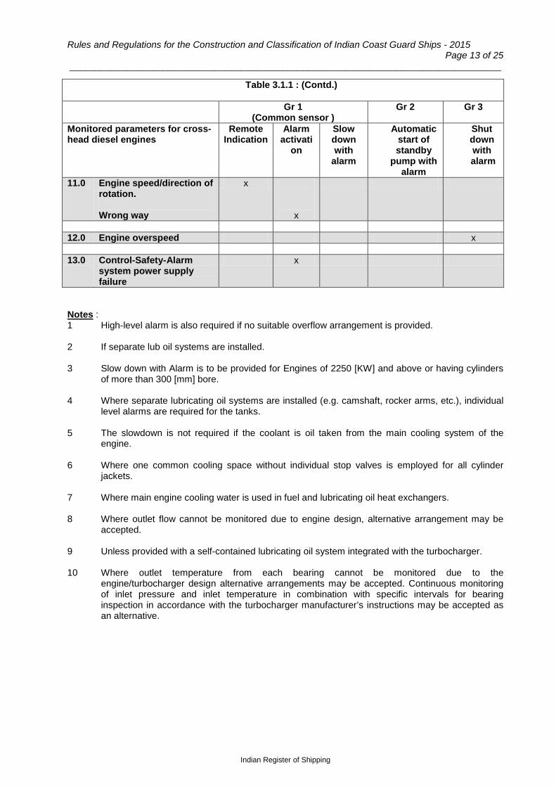
Rules and Regulations for the Construction and Classification of Indian Coast Guard Ships - 2015 Page 13 of 25
___________________________________________________________________________________
Table 3.1.1 : (Contd.)
Gr 1 (Common sensor )
Gr 2 Gr 3
Monitored parameters for cross-head diesel engines
Remote Indication
Alarm activati
on
Slow down with
alarm
Automatic start of standby
pump with alarm
Shut down with
alarm
11.0 Engine speed/direction of rotation. Wrong way
x x
12.0 Engine overspeed x 13.0 Control-Safety-Alarm
system power supply failure
x
Notes : 1 High-level alarm is also required if no suitable overflow arrangement is provided. 2 If separate lub oil systems are installed. 3 Slow down with Alarm is to be provided for Engines of 2250 [KW] and above or having cylinders
of more than 300 [mm] bore. 4 Where separate lubricating oil systems are installed (e.g. camshaft, rocker arms, etc.), individual
level alarms are required for the tanks. 5 The slowdown is not required if the coolant is oil taken from the main cooling system of the
engine. 6 Where one common cooling space without individual stop valves is employed for all cylinder
jackets. 7 Where main engine cooling water is used in fuel and lubricating oil heat exchangers. 8 Where outlet flow cannot be monitored due to engine design, alternative arrangement may be
accepted. 9 Unless provided with a self-contained lubricating oil system integrated with the turbocharger. 10 Where outlet temperature from each bearing cannot be monitored due to the
engine/turbocharger design alternative arrangements may be accepted. Continuous monitoring of inlet pressure and inlet temperature in combination with specific intervals for bearing inspection in accordance with the turbocharger manufacturer’s instructions may be accepted as an alternative.
Indian Register of Shipping
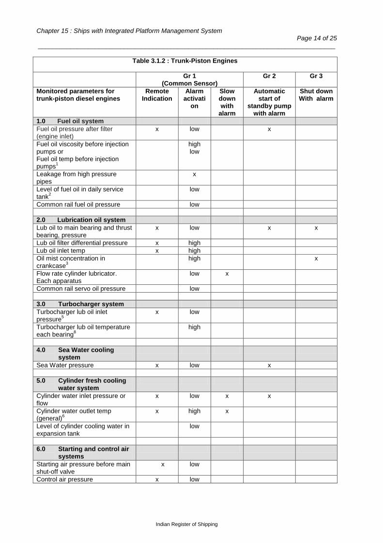
Chapter 15 : Ships with Integrated Platform Management System Page 14 of 25
___________________________________________________________________________________
Table 3.1.2 : Trunk-Piston Engines
Gr 1 (Common Sensor)
Gr 2 Gr 3
Monitored parameters for trunk-piston diesel engines
Remote Indication
Alarm activati
on
Slow down with
alarm
Automatic start of
standby pump with alarm
Shut down With alarm
1.0 Fuel oil system Fuel oil pressure after filter (engine inlet)
x low x
Fuel oil viscosity before injection pumps or Fuel oil temp before injection pumps1
high low
Leakage from high pressure pipes
x
Level of fuel oil in daily service tank2
low
Common rail fuel oil pressure low 2.0 Lubrication oil system Lub oil to main bearing and thrust bearing, pressure
x low x x
Lub oil filter differential pressure x high Lub oil inlet temp x high Oil mist concentration in crankcase3
high x
Flow rate cylinder lubricator. Each apparatus
low x
Common rail servo oil pressure low 3.0 Turbocharger system Turbocharger lub oil inlet pressure5
x low
Turbocharger lub oil temperature each bearing8
high
4.0 Sea Water cooling
system
Sea Water pressure x low x 5.0 Cylinder fresh cooling
water system
Cylinder water inlet pressure or flow
x low x x
Cylinder water outlet temp (general)6
x high x
Level of cylinder cooling water in expansion tank
low
6.0 Starting and control air
systems
Starting air pressure before main shut-off valve
x low
Control air pressure x low
Indian Register of Shipping

Rules and Regulations for the Construction and Classification of Indian Coast Guard Ships - 2015 Page 15 of 25
___________________________________________________________________________________
Table 3.1.2 : (Contd.)
Gr 1 (Common Sensor)
Gr 2 Gr 3
Monitored parameters for trunk-piston diesel engines
Remote Indication
Alarm activati
on
Slow down with
alarm
Automatic start of
standby pump with alarm
Shut down With alarm
7.0 Scavenge air system Scavenge air receiver temp high 8.0 Exhaust Gas system Exhaust gas temp after each cylinder7
x high x
Exhaust gas temp after each cylinder. Deviation from average7
high
9.0 Engine speed x 10.0 Engine overspeed x 11.0 Control-Safety-Alarm
system power supply failure
x
Notes : 1 For heavy fuel oil burning engines only. 2 High-level alarm is also required if no suitable overflow arrangement is provided. 3 Alarm and automatic shut off is to be provided for Engines of 2250 [KW] and above or having
cylinders of more than 300 [mm] bore. One oil mist detector for each engine having two independent outputs for initiating the alarm and shut-down would satisfy the requirement for independence between alarm and shut-down system.
4 If necessary for the safe operation of the engine. 5 Unless provided with a self-contained lubricating oil system integrated with the turbocharger. 6 Two separate sensors are required for alarm and slow down. 7 For engine power > 500 kW/cyl. 8 Where outlet temperature from each bearing cannot be monitored due to the engine/ turbocharger design alternative arrangements may be accepted. Continuous monitoring of inlet pressure and inlet temperature in combination with specific intervals for bearing inspection in accordance with the turbocharger manufacturer’s instructions may be accepted as an alternative.
Indian Register of Shipping
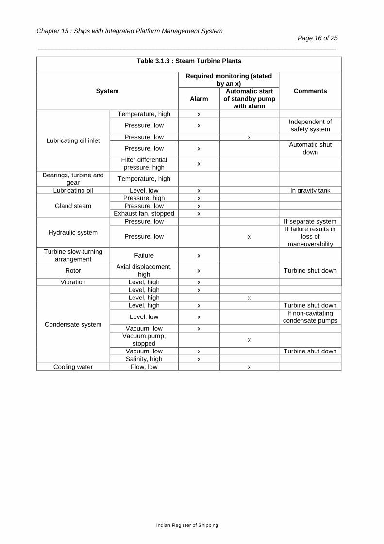
Chapter 15 : Ships with Integrated Platform Management System Page 16 of 25
___________________________________________________________________________________
Table 3.1.3 : Steam Turbine Plants
System
Required monitoring (stated by an x)
Comments Alarm
Automatic start of standby pump
with alarm
Lubricating oil inlet
Temperature, high x
Pressure, low x Independent of safety system
Pressure, low x
Pressure, low x Automatic shut down
Filter differential pressure, high x
Bearings, turbine and gear Temperature, high
Lubricating oil Level, low x In gravity tank
Gland steam Pressure, high x Pressure, low x
Exhaust fan, stopped x
Hydraulic system
Pressure, low If separate system
Pressure, low x If failure results in
loss of maneuverability
Turbine slow-turning arrangement Failure x
Rotor Axial displacement, high x Turbine shut down
Vibration Level, high x
Condensate system
Level, high x Level, high x Level, high x Turbine shut down
Level, low x If non-cavitating condensate pumps
Vacuum, low x Vacuum pump,
stopped x
Vacuum, low x Turbine shut down Salinity, high x
Cooling water Flow, low x
Indian Register of Shipping

Rules and Regulations for the Construction and Classification of Indian Coast Guard Ships - 2015 Page 17 of 25
___________________________________________________________________________________
Table 3.1.4 : Monitoring of Shafting and Propeller Plant
System
Required monitoring (stated by an x)
Comments Alarm
Automatic start of standby pump
with alarm
Shafting
Temperature, thrust bearing, high x
Automatic or manual reduction, see 3.1.14.
Two sensors for diesel engine built in thrust bearing and for steam turbine plants
Temperature, shaft bearing, high x
Shaft power ≥ 1500 [kW]. Sensor to be located near the bearing surface
Temperature, stern tube bearing, high x
Shaft power ≥ 15000 [kW]. Sensor to be located near the
bearing surface at the area of highest load
Level, stern tube lubricating oil gravity
tank, low x
Controllable pitch propeller
Pressure, servo oil, low x
Pressure, servo oil, low x
Temperature, servo oil, high x Shaft power ≥ 1500
[kW]
Gear
Pressure, lubricating oil inlet, low x
Pressure, lubricating oil inlet, low x
Pressure, lubricating oil inlet, low Automatic or manual
stop, see 3.1.11 Temperature,
lubricating oil, high x
Hydraulic coupling Pressure, oil, low x If separate system
Pressure, oil, low x If failure results in loss of maneuverability
Indian Register of Shipping

Chapter 15 : Ships with Integrated Platform Management System Page 18 of 25
___________________________________________________________________________________
Table 3.1.5 : Monitoring of Electric Power Generating Plant
System
Required monitoring (stated by an x)
Comments Alarm
Automatic shut down of prime
mover with alarm
Generators driven by trunk
piston IC engines
Lubricating oil pressure, low x x
Lubricating oil temperature, high x
Fuel oil leakage from high pressure pipes x
Oil mist concentration in crank case, high1 x x
Pressure or flow of cooling water, low x
Temperature of cooling water or cooling air, high x
Level in cooling water expansion tank, low x If not connected to main
system Level in fuel oil daily
service tank, low x
Starting air pressure, low x Over speed activated x
Fuel oil viscosity before injection pumps or fuel oil
temp before injection pumps, low/ high
x For heavy fuel oil burning engines only
Exhaust gas temperature after each cylinder, high x For engine power above
500 kW/cyl Common rail servo oil
pressure, low x
Common rail fuel oil pressure, low x
Voltage, high x Voltage, low x
Frequency, low x Disconnection of non-essential consumers x
1. Alarm and automatic shut off is to be provided for Engines of 2250 [KW] and above or having cylinders of more than 300 [mm] bore. One oil mist detector for each engine having two independent outputs for initiating the alarm and shut-down would satisfy the requirement for independence between alarm and shut-down system.
Steam turbine
Temperature, lubricating oil, high x
Pressure, lubricating oil inlet, low x Independent of safety
system Pressure, lubricating oil
inlet, low x
Pressure, condenser, high x Pressure, condenser, high x Pressure, steam inlet line,
low x
Axial displacement rotor, large x Multistage turbines
Indian Register of Shipping

Rules and Regulations for the Construction and Classification of Indian Coast Guard Ships - 2015 Page 19 of 25
___________________________________________________________________________________
Table 3.1.6 : Monitoring of Steam Generating Plant
System
Required monitoring (stated by an x)
Comments Alarm
Automatic shut down of boiler
with alarm Main Steam and Feed Water Installation
Boiler water
Level, high x Level, high x Turbine shut down
Level, low x Independent of safety system
Level, low x Water circulation Stopped x Forced circulation boilers Combustion air
supply Fan stopped x
Uptake gas Temperature, high x For fire detection
Fuel oil Pressure, low x
Pressure, low Automatic start of standby pump with alarm
Fuel oil temperature or
viscosity
Heavy oil, high x
Heavy oil, low x
Oil burner Pressure of atomizing medium, low x
Steam Pressure, high x Pressure, low x Turbine slow down
Temperature, high x
Ignition/flame Ignition/flame failure x Separate monitoring and
fuel shutoff for each burner
Feed water system
Atmospheric tank level, high x
Atmospheric tank level, low x
Deaerator level, high x Deaerator level, low x Deaerator pressure,
high x
Deaerator pressure, low x
Feed water
Temperature, high x Pressure, low x
Pressure, low Automatic start of standby pump with alarm
High pressure feed water
heaters Level, high x
Fresh water generator Salinity, high x Automatic stop of fresh
water generator
Indian Register of Shipping

Chapter 15 : Ships with Integrated Platform Management System Page 20 of 25
___________________________________________________________________________________
Table 3.1.6 : (Contd.)
System
Required monitoring (stated by an x)
Comments Alarm
Automatic shut down of boiler
with alarm Auxiliary Boiler Plant
Non-dual pressure boiler
Water level, high x
Water level, low x Independent of safety system
Water level, low x
Dual pressure boilers
Water level primary system, low x Independent of safety
system Primary system, low x Secondary system,
high x
Secondary system, low x
Water circulation Stopped x Forced circulation boilers Fuel oil
temperature or viscosity
Heavy oil, high x
Heavy oil, low x
Steam
Pressure, high x
Pressure, high x
When the automatic control system does not
cover the entire load range from zero load
Temperature, high x For superheated steam ≥ 350°C
Feed water Salinity, high x Boiler pressure ≥ 20 bar Condenser Pressure, high x
Ignition/flame Failure x Separate monitoring and
fuel shut off for each burner
Table 3.1.7 : Monitoring of Tanks
Item Alarm Comments
Sludge and drain tanks, level high x All tanks arranged with automatic filling are to
have alarm for both high and low level Service tanks, level, low x Expansion tanks, level low x Circulating tanks, level low x
Indian Register of Shipping

Rules and Regulations for the Construction and Classification of Indian Coast Guard Ships - 2015 Page 21 of 25
___________________________________________________________________________________
Table 3.1.8 : Monitoring of Miscellaneous Items
Item Alarm Comments Bilges and bilge wells
Engine room, level high x 2 independent alarm circuits, minimum 2 detectors Purifiers
Lubricating oil inlet, temperature, high x
Fuel oil inlet, temperature high x Fuel oil inlet, temperature low x For heavy fuel oil Water seal, loss x Alarm and safety systems, power failure x
Electric, pneumatic, hydraulic Remote control system, power failure x
Steering gear
Electric motors, stopped x Manual start of standby motor from the bridge, alternatively automatic start with alarm
3.2 Electric power supply 3.2.1 Means are to be provided to avoid overloading of supply units. 3.2.2 The ship's main power supply is to be arranged according to one of the following methods: - In ships where one generator is sufficient to cover normal load at sea there is to be an arrangement
for automatic start and connection to the main switchboard of a standby generator. Start and connection are to be completed within 30 seconds;
- In ships where more than one generator is necessary to cover normal load at sea, there is, in order to
maintain maneuverability, to be an arrangement for necessary tripping non-essential consumers in case of disconnections of, or failures which will lead to disconnection of a generator.
3.2.3 Standby units are normally to have separate cooling water and lubricating oil pumps. Alternatively, automatic start of standby pumps is to be arranged when they also serve other generating sets. 3.2.4 In the event of automatic start of standby power supply unit, automatic start of essential machinery is to follow in a pre-determined sequence. Units necessary for maneuvering of the ship are regarded as essential machinery. Starting air compressors, bilge, ballast and fire pumps need not be included. 3.2.5 When the maneuverability of the ship is independent of electric power, the requirements of 3.2.3 and 3.2.4 do not apply. 3.2.6 For essential consumers having power supply from the lighting system, precautions against power failure are to be similar to those taken for units having power supply from the main generators, e.g. the following means may be applied: - adequate automatic emergency lighting for access to standby transformer for the lighting system and
operating gear for manual connection; - automatic connection of standby transformer; - parallel connection of a sufficient number of transformers, and arrangement for selective
disconnection; - automatic connection of emergency source of power; and - dividing the system in two or more circuits with automatic switch over. In this context, essential consumers are units and equipment necessary for maneuvering of the ship, including navigation lights and sufficient lighting (either as part of the normal lighting or as separate emergency lighting) in the engine room, on the bridge, in the chartroom, in all passageways and stairways of the accommodation.
Indian Register of Shipping

Chapter 15 : Ships with Integrated Platform Management System Page 22 of 25
___________________________________________________________________________________
Section 4
Ships fitted with Internal Combustion Propulsion Engines
of less than 1000 [kW]
4.1 General 4.1.1 The requirements of this section are applicable to internal combustion propulsion engines of less than 1000 [kW], in lieu of the requirements specified in Section 3. Monitoring of parameters listed in 4.2 will normally be required. Other combinations of measuring points other than those listed may be accepted, when the chosen monitoring can detect fault conditions in an equivalent satisfactory manner. 4.1.2 The limitations of installations in ships with propulsion machinery of less than 1000 [kW] apply to the extent of monitoring only. The system arrangement is to be in accordance with Sec.2, unless otherwise specially stated. 4.2 Alarm system 4.2.1 Alarm is to be activated for the following fault conditions:
- fire in engine room; - bilge level, high; - variable pitch propeller, servo oil pressure, low; - reduction gearing, lubricating oil pressure, low; - power failure for alarm and remote control systems; - main engine lubricating oil pressure, low; - main engine cooling water (sea and fresh water) pressure, low. Indication of cooling water
pressure on the bridge will be accepted as an alternative to alarms; - main engine cooling water temperature, high; - main engine cooling water expansion tank level - low; and - low lubricating oil pressure and high cooling water temperature for electric power generating
plants greater than 35 [kW]. 4.3 Arrangements on bridge 4.3.1 In the event of fault condition the parameters, required to be monitored as per 4.2, are to activate individual or groupwise alarm signals on the bridge. 4.3.2 The following parameters are to be indicated on the bridge:
- rpm; - propeller pitch (controllable pitch propeller); - starting air pressure (reversible engine); - direction of rotation (reversible engine);
Indian Register of Shipping

Rules and Regulations for the Construction and Classification of Indian Coast Guard Ships - 2015 Page 23 of 25
___________________________________________________________________________________
- lubricating oil pressure for main engines and reduction gearing. This indication may be omitted if the pressure is monitored in accordance with the requirements of Sec.3.
4.4 Electric power supply 4.4.1 When the maneuverability of the ship is dependent on electric power, precautions are to be taken to avoid power supply units from being overloaded.
Section 5
Precautions against Fire
5.1 Oil fuel systems 5.1.1 Fuel oil injection pipes on all engines, irrespective of cylinder bore, are to be effectively shielded and secured. Safe drainage is to be provided for the leak- off oil. 5.1.2 Oil purifiers, burner units, and similar equipments, are to be efficiently shielded in order to prevent oil spray and leakages from reaching electric motors, hot surfaces, etc. 5.1.3 Where daily service oil fuel tanks are filled automatically, or by remote control, means are to be provided to prevent overflow spillage. Other equipment which treat flammable liquids automatically (e.g. oil fuel purifiers) are to be installed, as far as practicable, in a special space reserved for purifiers and their heaters are to have arrangements to prevent overflow spillage. 5.1.4 Where daily service oil fuel tanks or settling tanks are fitted with heating arrangements, a high temperature alarm is to be provided if the flash point of the oil fuel can be exceeded. 5.2 Fire detection 5.2.1 Fire detectors are to be fitted in the machinery spaces. All potential fire outbreak points are to be effectively guarded. The fire detection systems as well as number and location of detectors are subject to approval in each case. A mixture of temperature and smoke/ionization detectors is recommended. Flame detectors should be used to cover large spaces, e.g. over the main engine. The location and minimum number of detectors should preferably be as follows:
a) One detector for each internal combustion engine, boiler front, oil purifier installation, electric power distribution board and for each separate room in machinery spaces;
b) If temperature detectors are used exclusively, detectors should be fitted under all horizontal
surfaces exceeding 10 [m2] with a maximum distance of 5 [m] between detectors; c) If smoke/ionization detectors are used exclusively, the number of detectors should not be less
than -
0.03.L.B L = total length of machinery spaces [m]; B = total breadth of machinery spaces [m];
d) The air flow in the machinery spaces under normal ventilation condition should be considered
when the location of smoke/ionization detectors is considered. 5.2.2 Heat detectors only are not accepted for fire detection in the engine room. 5.2.3 The fire detectors are to be arranged in sections /loops. There should be at least two loops for ships above 5000 GT.
Indian Register of Shipping
Chapter 15 : Ships with Integrated Platform Management System Page 24 of 25
___________________________________________________________________________________ 5.3 Fire detector indicator panel 5.3.1 A fire detector indicator panel is to be located in the navigating bridge area, the fire control station or in such a position that a fire in the machinery spaces will not render it inoperative. The panel is to indicate the source of fire in accordance with arranged fire zones by means of a visual signal.
Section 6
Testing of the System
6.1 Testing at supplier’s works 6.1.1 Any formal testing on the equipment to be supplied or prototype is to be witnessed by the IRS Surveyors and the representatives of Coast Guard Authority, for which advance notice is to be provided by the manufacturer. 6.1.2 The manufacturer of the IPMS system is to supply the following deliverables, to be kept at suitable shore based facility :
a) Special test equipment including software diagnostic tools and simulation models; b) Associated drawings and documentation used for production of the test equipment; and c) Users manual for the test equipment and the software.
6.2 Environmental testing 6.2.1 The IPMS hardware is to be qualified for usage in marine environment. Test Certificates are to be provided indicating compliance with relevant test requirements. Test requirements specified in IRS “Type approval certification scheme of Electrical equipment used for Control, Monitoring, Alarm and Protection Systems for use in Ships”, would be generally applicable. 6.3 Factory Acceptance Trials 6.3.1 The IPMS Supplier is to prepare and submit a detailed Factory Acceptance Trials plan. The plan is to state how the IPMS supplier will demonstrate that the delivered system shall meet the functional and performance requirements. Thereafter, a Factory Acceptance Trials procedure shall be produced, which shall be conducted prior to the delivery and witnessed by the IRS Surveyors and the representatives of Naval Authority.
6.4 Shipboard installation and trials
6.4.1 After installation of the plant has been completed, functional testing of the plant is to be carried out in the presence of the Surveyors and also Coast Guard Authority’s representatives. 6.4.2 Only after all work in connection with adjustments and starting of the various units of the plant has been completed, sea trials are to be carried out. The sea trials are to include at least 4 hours of continuous operation with unattended machinery spaces. 6.4.3 The builders are to prepare a detailed test programme. The test programme is to be kept onboard, all filled in and signed by the Surveyors. 6.4.4 Where considered necessary by the Surveyor, vibrations and temperatures of exposed units are to be measured. If it is found that a unit is subjected to strains beyond the limits specified for it, precautions are to be taken to improve the conditions. 6.4.5 Recording of important automatically controlled parameters may be required as part of the testing.
Indian Register of Shipping

Rules and Regulations for the Construction and Classification of Indian Coast Guard Ships - 2015 Page 25 of 25
___________________________________________________________________________________
6.5 Monitoring systems 6.5.1 Failure conditions are to be simulated as realistically as possible, preferably by letting the monitored parameters exceed the alarm and safety limits. The alarm and safety limits are to be recorded in the test programme. 6.5.2 Any calibrations of sensors prior to installation onboard are to be approved by the Surveyor. 6.6 Automatic and remote control systems 6.6.1 Automatic control systems are to be tested by varying the parameters having effect upon the controlled process. As far as practicable it is to be verified that all normal control ranges are covered. 6.6.2 All tests included in the test programme for the remote control system are to be carried out without any manual assistance from the engine room, and all systems are to be in operation as normal for unattended periods. 6.7 Blackout test 6.7.1 During bridge control at about half speed ahead, a failure is to be simulated to cause automatic stop of electric power generator. 6.7.2 For installations with automatic start and connection of standby units, it is to be ensured that the automatic start of standby power supply unit and machinery necessary for maneuvering of the ship from the bridge is effected without manual intervention in the engine room. 6.7.3 For installations with two or more generator units run in parallel at a time, it is to be ensured that the stopped unit is automatically disconnected from the switchboard, and that the capacity of the remaining running unit(s) is adequate for propulsion and steering functions after automatic tripping of non-essential consumers.
End of Chapter
Indian Register of Shipping

Rules and Regulations for the Construction and Classification of Indian Coast Guard Ships - 2015 Page 1 of 24
___________________________________________________________________________________
Chapter 16
Integrated Bridge System
Contents Section
1 General
2 Documentation
3 System Requirements
4 Operational and Technical Requirements
5 Work Station
6 Navigational Equipment Requirements
7 Bridge Navigational Watch Alarm System
8 Tests and Trials
Section 1
General
1.1 Application 1.1.1 This chapter provides the requirements for integrated bridge system that allows simplified and
centralized bridge operation of the main functions of navigation, communication and manouvering of the vessel including monitoring of such critical systems.
1.1.2 Ships fitted with integrated bridge system complying with the requirements of this chapter will be
eligible to be assigned additional class notation ‘IBS’. 1.2 Functional requirements 1.2.1 Following functions are to be carried out from the integrated bridge system
- Passage execution will cover - i) route monitoring ii) route planning
- Communication system - Monitoring of machinery installations - Navigational safety and security.
1.2.2 Pollution monitoring and monitoring of HVAC may also be carried out from the integrated bridge
system if considered necessary by Coast Guard Authority.
Indian Register of Shipping

Chapter 16 : Integrated Bridge System Page 2 of 24
___________________________________________________________________________________ 1.3 International standards and IMO requirements 1.3.1 The following international standards and IMO requirements are referred to in this chapter.
- IEC 60945:1996, Maritime navigation and radio-communication equipment and systems – General requirements – Methods of testing and required test results.
- IEC:61162 (all parts) Maritime navigation and radio-communication equipment and systems
– Digital interfaces.
- ISO 8468:1990 – Ship’s bridge layout and associated equipment – requirements and guidelines.
- IMO International Convention for the Safety of Life at Sea (SOLAS), as amended.
- IMO A.823(19) – Performance standards for automatic radar plotting aids (ARPAs).
- IMO A.830(19) – Code on alarms and indicators (amendments to IMO 686:1991).
- IMO A.694(17) – General requirements for shipborne radio equipment forming part of the
global maritime distress and safety system (GMDSS) and for electronic navigational aids.
- IMO MSC.64(67) – Annex I – Performance standards for integrated bridge systems.
- IMO MSC.64(67) – Annex 4 – Recommendation on performance standards for radar equipment.
- IMO MSC/Circular 566:1991 – Provisional guideline on the conduct of trials in which the
officer of the navigational watch acts as the sole lookout in periods of darkness. 1.4 Definitions 1.4.1 Configuration of complete system : all operational functions of the IBS as installed. 1.4.2 Configuration available : operation(s) allocated to and available at each workstation. 1.4.3 Configuration in use : operation(s) and task(s) currently in use at each workstation. 1.4.4 Connectivity : a complete data link and the presence of valid data. 1.4.5 Essential functions : functions related to determination, execution and maintenance of safe course, speed and position of the ship in relation to the waters, traffic and weather conditions. Such functions include but are not limited to:
- Route planning - Navigation - Collision avoidance - Manoeuvring - Docking - Monitoring of internal safety systems - External and internal communication related to safety in bridge operation and distress situations.
1.4.6 Essential information : that information which is necessary for the monitoring of essential functions. 1.4.7 Functionality: ability to perform an intended function. The performance of a function normally involves a system of displays and instrumentation. 1.4.8 Statutory requirements : IMO Conventions, Regulations, Resolutions, Codes, Recommendations, Guidelines, Circulars and related ISO and IEC standards.
Indian Register of Shipping
Rules and Regulations for the Construction and Classification of Indian Coast Guard Ships - 2015 Page 3 of 24
___________________________________________________________________________________
1.4.9 Integrated bridge system (IBS) : any combination of systems which are interconnected in order to allow centralized access to sensor information from workstations to perform two or more of the following operations:
- Passage execution - Communications - Machinery monitoring - Pollution monitoring, if considered necessary - HVAC if considered necessary.
1.4.10 Integrity : ability of a system to provide users with accurate, timely, complete and unambiguous information and warnings within a specified time when the system is not in use. 1.4.11 Latency : time interval between an event and the resulting information, including time for processing, transmission and reception. 1.4.12 Multi-function display : a composite visual display unit/s which can present, either simultaneously or through a series of selectable pages, information from more than one operation of a IBS. 1.4.13 Novel systems or equipment : systems or equipment which embody new features not fully covered by provisions of SOLAS V but which provide at least equivalent standard of safety ( SOLAS Regulation 19.6). 1.4.14 Part : individual subsystem, equipment or module. 1.4.15 Performance check : a representative selection of short qualitative tests, to confirm correct operation or essential functions of the IBS. 1.4.16 Sensor : a device which provides information to or is controlled or monitored by the IBS. 1.4.17 Workstation : A position at which one or several tasks, constituting a particular activity, is carried out. 1.4.18 Navigation workstation : A workstation at which the navigator may carry out all tasks relevant for deciding, executing and maintaining course and speed in relation to waters and traffic. The instrumentation and controls at the navigation workstation should allow the navigator to:
- Analyse the traffic situation; - Monitor position, course, track, speed, time, propeller revolutions and pitch, rudder angle, depth
of water, rate of turn and wind speed and direction; - Alter course and speed; - Effect internal and external communications; - Give and receive sound signals; - Control navigational lights; - Monitor and acknowledge navigational alarms; - Confirm his well-being and watch-keeping awareness; and - Record navigational data.
1.4.19 Main steering position : That part of the navigation workstation where those controls and instrumentation relevant to controlling the ship’s course are located. 1.4.20 Conning position : A place on the bridge which is used by navigators when commanding, manoeuvring and controlling a ship.
Indian Register of Shipping

Chapter 16 : Integrated Bridge System Page 4 of 24
___________________________________________________________________________________ 1.4.21 Voyage planning workstation : A workstation at which the navigator may carry out the following tasks without affecting the actual navigation of the vessel:
- Examine and update charts and other relevant documentation; - Plan a voyage as a series of waypoints, courses, speeds and turns; - Calculate an estimated time of arrival at various points on the voyage; and - Determine and plot the ship’s position.
1.5 Abbreviations 1.5.1 Abbreviations used in this Chapter : AIS : Automatic identification system ARPA : Automatic radar plotting aid DSC : Digital selective calling EGC : Enhanced group call EPIRB : Emergency position indicating radio beacon GMT : Greenwich Mean Time HF : High Frequency INMARSAT : International Mobile Satellite Organization ISO : International Standards Organization ITU-R : International Telecommunication Union – radio sector IBS : Integrated Bridge System ITU-T : International Telecommunication Union – telecommunication sector MARPOL : IMO Convention for the prevention of pollution by ships MEPC : Marine Environmental Protection Committee of IMO MF : Medium Frequency MSC : Maritime Safety Committee of IMO NAV : IMO Subcommittee on Safety of Navigation NAVTEX : System for broadcast and reception of maritime safety information OOW : Officer of the watch r.p.m. : Revolutions per minute UTC : Universal coordinated time VDU : Visual display unit VHF : Very high frequency ECDIS : Electronic Chart Display Information System GLONASS Global Orbiting Navigating satellite Systems
1.6 Equipment list 1.6.1 The list of equipment required for IBS notation is to be as given in Table 6.1.
Indian Register of Shipping
Rules and Regulations for the Construction and Classification of Indian Coast Guard Ships - 2015 Page 5 of 24
___________________________________________________________________________________
Section 2
Documentation
2.1 Documents to be submitted 2.1.1 Relevant plans and data are to be submitted for approval and/or information as follows. Unless indicated otherwise, plans submitted by the shipyard and those submitted by the equipment manufacturer are to be in triplicate. A complete layout and dimensional details of the bridge area and workstations installed therein. This is to include:
a) Arrangements of windows, including dimensions and angles of inclination, dimensions of frames, height above deck surface of upper and lower edges, type of glass and details of clear view arrangements (wipers, fresh water wash, de-icing / de-misting, sunscreens, etc.)
b) Fields of vision from the bridge workstations, including any blind sectors caused by obstructions
outside of the wheelhouse.
c) Location and arrangement of workstations, including dimensions of consoles, layout of instrumentation and controls, handrails, seating, etc.
d) Clearances between floor and ceiling or between floor and the underside of ceiling mounted
instruments, throughout the wheelhouse.
e) Arrangements for the general illumination of the bridge and the individual illumination of workstation instruments and controls.
f) Details of wheelhouse ventilation and heating systems.
g) Details of internal communication systems operable from the bridge.
h) Arrangements / details of exterior catwalk in front of bridge windows.
i) Details of non-skid flooring
j) Details of wheelhouse doors, including hold-back arrangements.
k) Location of toilet.
l) Arrangements for drainage of bridge decks.
m) Arrangements / details as to the measures to be taken to minimize hazards to personnel.
2.1.2 A list of navigational equipment. This is to include for each item the manufacturer’s name and code number, together with copies of relevant type approval certificates. 2.1.3 A complete operational description of the relevant monitoring systems including a list of alarms and displays. This may be accomplished by means of simplified block diagrams of navigation equipment, internal communication systems and watch monitoring and alarm transfer systems and central alarm panel (where provided) including a list of alarms. 2.1.4 A simplified one-line diagram of power supplies to the bridge equipment, circuit protection ratings and settings, cable sizes, rating of connected loads, detailed description and interactions, etc. 2.1.5 Operating / technical manuals for the installed navigational equipment / systems is to be submitted for information.
Indian Register of Shipping

Chapter 16 : Integrated Bridge System Page 6 of 24
___________________________________________________________________________________ 2.1.6 Sea trial test schedule. 2.1.7 Details and arrangements of the workstations and systems. 2.1.8 The sea trial program is to include test details of the electronic chart display and information systems (EDCIS) and integrated bridge system (IBS).
Section 3
System Requirements
3.1 General 3.1.1 The IBS is to comply with all applicable statutory requirements as defined in para 1.3. Parts of the system executing multiple operations are to meet the requirements specified for each individual function they can control, monitor or perform. 3.1.2 Each part of a IBS is to meet the relevant requirements of IMO Resolution A.694(17) (as amended) as detailed in IEC 60495. 3.1.3 Any additional requirements of Coast Guard authority including system configuration are also to be complied with. 3.2 Integration The system should provide functional integration meeting the following requirements:
a) The functionality of the IBS should ensure that its operation is at least as effective as for stand-alone equipment.
b) Continuously displayed information should be reduced to the minimum necessary for safe
operation of the ship. Supplementary information should be readily accessible.
c) Where multifunction displays and controls are used to perform functions necessary for safe operation of the ship they should be duplicated and interchangeable.
d) It should be possible to display the complete system configuration, the available configuration
and the configuration in use.
e) Each part to be integrated should provide details of its operational status and the latency and validity of essential information. Means should be provided within the IBS to make use of this information.
f) An alternative means of operation should be provided for essential functions.
g) An alternative source of essential information should be provided. The IBS should identify loss of
either source.
h) The source of information (sensor, result of calculation or manual input) should be displayed continuously or upon request.
i) IBS is to be integrated with following ship systems:
- Ring Laser Gyros - Echo Sounder - Anemometer - EM Log - GPS
Indian Register of Shipping
Rules and Regulations for the Construction and Classification of Indian Coast Guard Ships - 2015 Page 7 of 24
___________________________________________________________________________________
- Steering System with Autopilot - Analog Video of Navigation Radar - Radar Data Distribution Unit (RDDU) - Automatic Identification System (AIS) - Integrated Platform Management System (including CCTV) - Radio Receiver Beacon (RRB) - Transmitting Magnetic Compass - Any other system as identified by Indian Navy.
3.3 Data exchange and data logging 3.3.1 Interfacing within the IBS is to comply with IEC 61162 (as amended), as applicable. 3.3.2 Data exchange is to be consistent with safe operation of ship. 3.3.3 The integrity of the data flowing on the network is to be ensured. 3.3.4 A failure in the connectivity is not to affect independent functionality. 3.3.5 The network is to be such that in the event of a single failure between nodes a clear indication of the failure is available, the sensors and displays on the network continue to operate and the data transmission between them is maintained. 3.4 Failure analysis 3.4.1 A failure analysis is to be performed and documented. 3.4.2 Parts, functions and connectivity are to be identified. 3.4.3 Possible failures of parts and connectivity associated with essential functions and information are to be identified. 3.4.4 Consequences of failures with respect to operation, function or status of the IBS are to be identified. 3.4.5 Each failure is to be classified with respect to its impact on the IBS taking into account relevant characteristics, such as detectability, diagnosability, testability, replaceability and compensating and operating provisions. 3.4.6 The results of the failure analysis are to confirm the possibility of continued safe operation of the ship. 3.5 Quality Assurance 3.5.1 The IBS is to be designed, developed, produced, installed and serviced by companies certified to ISO 9001:2000 Standard. 3.6 Alarm management 3.6.1 The IBS alarm management, as a minimum, is to comply with the requirements of “IRS Type approval certification scheme of Electrical equipment used for Control, Monitoring, Alarm and Protection Systems for use in Ships”. 3.6.2 Appropriate alarm management on priority and functional groups is to be provided within the IBS. 3.6.3 The number of alarm types and their release are to be kept as low as possible by providing indications for information of lower importance. 3.6.4 Alarms are to be displayed so that the alarm reason and resulting functional restrictions can be easily understood. Indications are to be self-explanatory.
Indian Register of Shipping

Chapter 16 : Integrated Bridge System Page 8 of 24
___________________________________________________________________________________ 3.6.5 Alarms are to be prioritized as follows:
a) emergency alarms : Alarms which indicate that immediate danger to human life or to the ship and its machinery exists and that immediate action is to be taken.
b) Distress, urgency and safety alarms: Alarms which indicate that a mobile unit or a person is in
distress, or the calling station has a very urgent message concerning the safety of the mobile unit or person ,or has an important warning to transmit.
c) Primary alarms : Alarms which indicate a condition that requires prompt attention to prevent an
emergency condition as specified in statutory and classification rules and regulations.
d) Secondary alarms : Alarms which are not included above. 3.6.6 The following alarms are to be provided and are to be centralized for efficient identification. Repeater displays may be fitted on the bridge wings and at other appropriate positions on the bridge where necessary.
- Off-course - Off-track (where automatic track following is provided) - Way point approaching, (where automatic track following is provided) - Position fix inaccurate/lost - Loss of heading input - Loss of speed log input - Equipment or sub-system failure - Gyro mis-match - Echo-sounder - Radar CPA - Navigational light failure - Steering gear alarms - Bridge navigational watch alarm system failure.
The audible alarms at the central panel and the relevant workstation are to be silenced when acknowledged from either location. However, it is to be possible to acknowledge the flickering light and bring to steady state only from the relevant work station. 3.6.7 Manual adjustment of any of the facilities of the integrated bridge system is to reset automatically the watch safety interval timer. 3.7 Power system requirement 3.7.1 Power interruptions and shutdown 3.7.1.1 If subjected to an orderly shut-down, the IBS should, upon turn-on, come to an initial default state. 3.7.1.2 After a power interruption full functionality of the IBS should be available after recovery of all subsystems. The IBS should not increase the recovery time of individual subsystem functions after power restoration. 3.7.1.3 If subjected to a power interruption the IBS should, upon restoration of power, maintain the configuration in use and continue automated operation, as far as practicable. Safety related automatic functions should only be restored upon confirmation by the operator. 3.7.2 Power supply 3.7.2.1 Attention is drawn to the relevant statutory requirement in respect of power supply to IBS which are to be complied with.
Indian Register of Shipping

Rules and Regulations for the Construction and Classification of Indian Coast Guard Ships - 2015 Page 9 of 24
___________________________________________________________________________________
3.7.2.2 The power to IBS should be supplied from : a) The main and emergency sources of electrical power with automated changeover through a local
distribution board with provision to preclude inadvertent shutdown. b) A transitional source of electrical power for a duration of not less than 1 min; and c) Where required, parts of the IBS should also be supplied from a reserve source of electrical power. d) Uninterrupted power supplies : Each vital item in the IBS shall be connected to an UPS. The UPS
shall supply this vital IBS equipment with continuous power during a loss of ships power for a minimum period of 60 minutes. The UPS shall prevent power transients as ship service power is lost and restored such that no loss of control or mal-operation of the IBS units results from these transitions. Battery charge circuits within each unit shall be capable of recharging the battery from 40% capacity to 80% capacity within 8 hours. They shall be protected from undercharge and overcharge. Battery charging shall be automatic and shall not affect normal unit operation.
3.8 Communication systems 3.8.1 A telephone system is to be provided to enable two-way speech communication between the wheelhouse and at least in the following locations: - machinery control station space;
- emergency steering position in the steering gear compartment; - commanding officers’ and navigating officers’ cabins, offices, mess and public rooms. 3.8.2 The bridge control is to have priority over the system. 3.8.3 A list of extension numbers is to be clearly displayed adjacent to each telephone. 3.9 Environmental conditions 3.9.1 An adequate air conditioning or mechanical ventilation system (upto 45°C ambient temperature), together with sufficient heating according to climatic conditions, is to be provided in order to maintain to 30°C and the humidity within the range 20 percent to 60 percent. The discharge of hot or cold air is not to be directed towards bridge personnel. Control of this system is to be provided in the wheelhouse. 3.10 EMI / EMC 3.10.1 Electrical and electronic equipment are to be installed so that electromagnetic interference does not affect the proper functioning of the navigational systems and equipment. Installation of the equipment in accordance with the guidelines and recommendations included in IEC 60533 Electrical and electronic installations in ships – Electromagnetic compatibility or an acceptable equivalent standard would generally be considered to meet the requirement.
Indian Register of Shipping
Chapter 16 : Integrated Bridge System Page 10 of 24
___________________________________________________________________________________
Section 4
Operational and Technical Requirements
4.1 Human factors 4.1.1 The IBS is to be capable of being operated by personnel holding appropriate certificates. 4.1.2 The man-machine interface (MMI) is to be designed to be easily understood and in a consistent style for all integrated functions. 4.1.3 Operational information is to be presented in a readily understandable format without the need to transpose, compute or translate. 4.1.4 Indications, which may be accompanied by a short low intensity acoustic signal are to occur when: - An attempt is made to execute an invalid function - An attempt is made to use invalid information. 4.1.5 If an input error is detected by the system it is to require the operator to correct the error immediately. Messages actuated by an input error are to guide the correct responses, e.g. not simply “Invalid entry”, but “Invalid entry, re-enter set point between 0 to 100”. 4.1.6 Layered menus are to be presented in a way which minimizes the added workload to find and return from the desired functions. 4.1.7 An overview is to be easily available to assist the operator in the use of a multiple page system. Each page is to have a unique identifier. 4.1.8 Where multi-function displays are used, they are to be in colour. Continuously displayed information and functional areas, e.g. menus, are to be presented in a consistent manner. 4.1.9 For actions which may cause unintended results, the IBS is to request confirmation from the operator. Note 1 : Examples of such actions are: - Attempting to change position and next waypoint while in track mode steering. - Attempting to switch on bow thruster when insufficient electrical power is available. 4.1.10 Functions requested by the operator are to be acknowledged or clearly indicated by the IBS on completion. 4.1.11 Default values, where applicable, are to be indicated by the IBS when requesting operator input. 4.1.12 The size, colour and density of text and graphic information presented on a display are to be such that it may be easily read from the normal operator position under all operational lighting conditions. (Ref ISO 8468-6.2.3). 4.1.13 Symbols used in mimic diagram are to be standardized throughout the system’s displays. 4.1.14 All information is to be presented on a background providing high contrast and emitting as little light as possible at night.
Indian Register of Shipping
Rules and Regulations for the Construction and Classification of Indian Coast Guard Ships - 2015 Page 11 of 24
___________________________________________________________________________________
4.2 Bridge layout 4.2.1 General a) The bridge shall be designed and arranged with the aim of: - Facilitating the tasks to be performed by the bridge team and the pilot in making full appraisal of the
situation and in navigating the ship safely under all operational conditions. - Promoting effective and safe bridge resource management. - Allowing for expeditious, continuous and effective information processing and decision-making by the
bridge team and the pilot. - Preventing or minimizing excessive or unnecessary work and any condition or distraction on the
bridge which may cause fatigue or interfere with the vigilance of the bridge team and the pilot. b) The design of bridges is to be governed by: - The functions and related tasks to be carried out on the bridge, systems used and methods of task
performance. - The range, layout and location of workstations required for performance of bridge functions - The fields of vision required for visual observations from each of the workstations. - Composition of the bridge team and the procedures required for safe operations under all identified
conditions. - The type and range of equipment to be provided for performance of the tasks at the individual
workstations and elsewhere on the bridge. 4.2.2 Arrangement a) The bridge configuration, arrangement of consoles and equipment location are to be such as to enable the officer of the watch to perform navigational tasks and other functions allocated to the bridge, as well as maintain an effective lookout. The following tasks are to be supported:
- Navigation and manoeuvring; - Monitoring; - Manual steering; - Docking; - Voyage planning; - Safety; - Communications; and - Conning.
b) Equipment and associated displays and indicators are to be sited at clearly defined workstations. c) Consoles, including the chart table, are to be positioned, so that the instrumentation they contain is mounted in such a manner as to face a person looking forward. As far as practicable, operating surfaces are to be normal to the operator’s line of sight. d) From other workstations within the wheelhouse it is to be possible to monitor the navigation workstation and to maintain an effective lookout. e) The main access to the bridge is to be by means of an internal stairway. Secondary external access
is also to be provided. f) Clear passage of at least 700 [mm] width is to be available to allow movement around the bridge with
a minimum of inconvenience. Particular attention is to be paid to the following routes which are to be as direct as possible:
Indian Register of Shipping
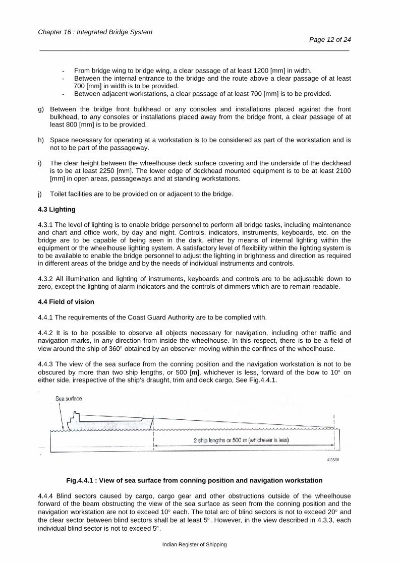
Chapter 16 : Integrated Bridge System Page 12 of 24
___________________________________________________________________________________
- From bridge wing to bridge wing, a clear passage of at least 1200 [mm] in width. - Between the internal entrance to the bridge and the route above a clear passage of at least
700 [mm] in width is to be provided. - Between adjacent workstations, a clear passage of at least 700 [mm] is to be provided.
g) Between the bridge front bulkhead or any consoles and installations placed against the front
bulkhead, to any consoles or installations placed away from the bridge front, a clear passage of at least 800 [mm] is to be provided.
h) Space necessary for operating at a workstation is to be considered as part of the workstation and is
not to be part of the passageway. i) The clear height between the wheelhouse deck surface covering and the underside of the deckhead
is to be at least 2250 [mm]. The lower edge of deckhead mounted equipment is to be at least 2100 [mm] in open areas, passageways and at standing workstations.
j) Toilet facilities are to be provided on or adjacent to the bridge. 4.3 Lighting 4.3.1 The level of lighting is to enable bridge personnel to perform all bridge tasks, including maintenance and chart and office work, by day and night. Controls, indicators, instruments, keyboards, etc. on the bridge are to be capable of being seen in the dark, either by means of internal lighting within the equipment or the wheelhouse lighting system. A satisfactory level of flexibility within the lighting system is to be available to enable the bridge personnel to adjust the lighting in brightness and direction as required in different areas of the bridge and by the needs of individual instruments and controls. 4.3.2 All illumination and lighting of instruments, keyboards and controls are to be adjustable down to zero, except the lighting of alarm indicators and the controls of dimmers which are to remain readable. 4.4 Field of vision 4.4.1 The requirements of the Coast Guard Authority are to be complied with. 4.4.2 It is to be possible to observe all objects necessary for navigation, including other traffic and navigation marks, in any direction from inside the wheelhouse. In this respect, there is to be a field of view around the ship of 360° obtained by an observer moving within the confines of the wheelhouse. 4.4.3 The view of the sea surface from the conning position and the navigation workstation is not to be obscured by more than two ship lengths, or 500 [m], whichever is less, forward of the bow to 10° on either side, irrespective of the ship’s draught, trim and deck cargo, See Fig.4.4.1.
Fig.4.4.1 : View of sea surface from conning position and navigation workstation
4.4.4 Blind sectors caused by cargo, cargo gear and other obstructions outside of the wheelhouse forward of the beam obstructing the view of the sea surface as seen from the conning position and the navigation workstation are not to exceed 10° each. The total arc of blind sectors is not to exceed 20° and the clear sector between blind sectors shall be at least 5°. However, in the view described in 4.3.3, each individual blind sector is not to exceed 5°.
Indian Register of Shipping

Rules and Regulations for the Construction and Classification of Indian Coast Guard Ships - 2015 Page 13 of 24
___________________________________________________________________________________
4.4.5 The horizontal field of vision from the conning position and the navigation workstation is to extend over an arc from more than 22.5° abaft the beam on one side, through forward, to more than 22.5° abaft the beam on the other side, See Fig.4.4.2.
Fig.4.4.2 : Horizontal field of view from conning position and navigation workstation 4.4.6 From the main steering position, the field of vision is to extend over an arc from dead ahead to at least 60° on each side, See Fig.4.4.3.
Fig.4.4.3 : Field of view from main steering position
4.4.7 From each bridge wing, the field of vision is to extend over an arc from at least 45° on the opposite bow through dead ahead and then aft to 180° from dead ahead, See Fig.4.4.4.
Indian Register of Shipping
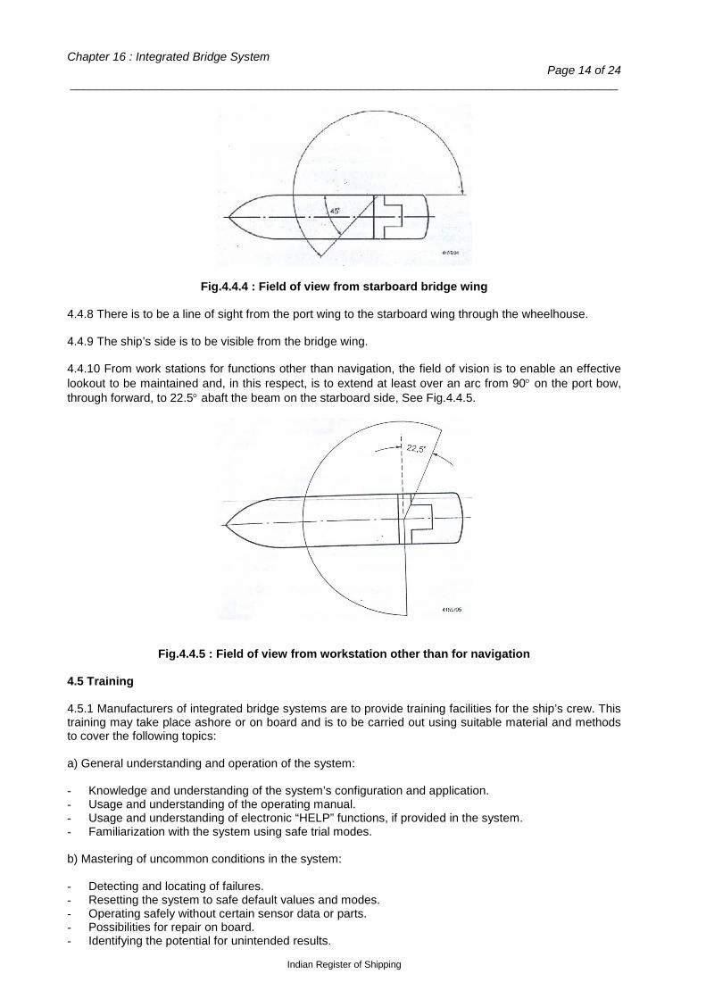
Chapter 16 : Integrated Bridge System Page 14 of 24
___________________________________________________________________________________
Fig.4.4.4 : Field of view from starboard bridge wing 4.4.8 There is to be a line of sight from the port wing to the starboard wing through the wheelhouse. 4.4.9 The ship’s side is to be visible from the bridge wing. 4.4.10 From work stations for functions other than navigation, the field of vision is to enable an effective lookout to be maintained and, in this respect, is to extend at least over an arc from 90° on the port bow, through forward, to 22.5° abaft the beam on the starboard side, See Fig.4.4.5.
Fig.4.4.5 : Field of view from workstation other than for navigation 4.5 Training 4.5.1 Manufacturers of integrated bridge systems are to provide training facilities for the ship’s crew. This training may take place ashore or on board and is to be carried out using suitable material and methods to cover the following topics: a) General understanding and operation of the system: - Knowledge and understanding of the system’s configuration and application. - Usage and understanding of the operating manual. - Usage and understanding of electronic “HELP” functions, if provided in the system. - Familiarization with the system using safe trial modes. b) Mastering of uncommon conditions in the system: - Detecting and locating of failures. - Resetting the system to safe default values and modes. - Operating safely without certain sensor data or parts. - Possibilities for repair on board. - Identifying the potential for unintended results.
Indian Register of Shipping
Rules and Regulations for the Construction and Classification of Indian Coast Guard Ships - 2015 Page 15 of 24
___________________________________________________________________________________
Section 5
Work Station
5.1 General 5.1.1 The bridge and workstation arrangement shall be based on relevant functional requirements and designed in accordance with established principles of ergonomics for safe and efficient operations, enabling the navigator to perceive all relevant information and execute pertinent actions with a minimum workload. 5.1.2 Workstations for additional functions may be located on the bridge provided the performance of such functions does not interfere with the tasks of maintaining safe control of the ship. Workstations for additional functions may include workstations for: - Extended communication functions - Monitoring and control of ballasting and cargo operations - Extended monitoring of machinery - Remote control of accommodation ladder, hatches and side ports - Miscellaneous. 5.2 Navigation workstation 5.2.1 A workstation for navigation is to be arranged to enable efficient operation by one person under normal operating conditions. The workstation area is to be sufficient to allow at least two operators to use the equipment simultaneously. The arrangement of instruments and controls is to allow the use of all instruments and controls necessary for navigating and manoeuvring in any normal working position. 5.2.2 An adequate conning position is to be provided close to the forward center window. If the view in the centerline is obstructed by large masts, cranes, etc. two additional conning positions giving a clear view ahead are to be provided, one on the port side and one on the starboard side of the centerline, no more than 5 [m] apart. In addition to the conning position, a second position with a view of the area immediately in front of the bridge superstructure is to be provided close to a forward window or, alternatively, the conning position is to be wide enough to accommodate two persons. 5.2.3 The main steering position is to be located on the ship’s centerline, unless the view ahead is obstructed by large masts, cranes, etc. In this case, the steering position is to be located a distance to starboard of the centerline sufficient to obtain a clear view ahead and special steering references for use by day and night are to be provided, e.g. sighting marks forward. 5.2.4 The following facilities are to be provided at the navigation workstation: - Radar and radar plotting facilities - Position-fixing system displays - Echo sounder display - Speed and distance indications - Gyrocompass displays - Magnetic compass display - Wind speed and direction indication - Steering controls and indication - Rate of turn indication - Course/track controls and indications - Main propulsion and thruster controls and indication - Watch safety system acknowledge - Watch safety system manual initiation - Internal communications system - VHF radiotelephone - Time indication - Window clear view controls - Navigation lights controls
Indian Register of Shipping
Chapter 16 : Integrated Bridge System Page 16 of 24
___________________________________________________________________________________ - Whistle control - Morse light keys - Wheelhouse/equipment lighting controls - Automatic ship identification system (AIS) information - Sound reception system where fitted.
Section 6
Navigational Equipment Requirements
6.1.1 Two functionally independent radars or alternative means are to be provided to determine and display the range and bearing of radar transponders and other surface craft, obstructions, buoys, shorelines and navigational marks. One of the radars is to operate in the X-band (9 GHz) and the other is to operate in the S-band (3 GHz). Both radars are to include automatic plotting aids to determine collision risks, and at least one radar is to be equipped with an automatic radar plotting aid (ARPA), capable of tracking at least 20 targets, while the other is to be either ARPA or an automatic tracking aid (ATA). 6.1.2 At least two different automatic position-fixing systems giving a continuous display of latitude and longitude are to be provided. One of these is to be GPS or equivalent. The other is to be by means of Radar or equivalent, depending on the area of operation. 6.1.3 A gyrocompass or alternative means for determining, displaying and transmitting the ship’s heading is to be provided. The heading information is to be used directly by the radars, radar plotting aids and automatic identification system. The gyrocompass is to be provided with a gyrocompass heading repeater located at the emergency steering position in the steering gear compartment and a gyrocompass bearing repeater allowing bearings to be taken over 360°. 6.1.4 An autopilot, track control system or alternative means of automatically maintaining the ship’s heading or a straight track is to be provided. At any time, it is to be possible to immediately restore manual control. 6.1.5 Where automatic track following is provided, sufficient warning is to be given of the approach of a waypoint, so that, in the event of no acknowledgement from the officer of the watch, there is adequate time for the backup navigator to reach the bridge and accept the change of course. 6.1.6 A speed log or alternative means of indicating the ship’s speed and distance through water is to be provided. The speed through water measurement is to be used directly by the ARPA as an aid to collision avoidance. 6.1.7 A speed log or alternative means of indicating the ship’s speed and distance over ground is to be provided. Speed over ground is to be indicated in both the fore-aft and athwartships directions. 6.1.8 Navigational systems and equipment are to be of a type approved by the national administration and in conformity with appropriate performance standards not inferior to those adopted by IMO from time to time. Documentary evidence to this effect is to be submitted. See SOLAS 1974 as amended, Ch.V, Reg.18. 6.1.9 Where alternative means of fulfilling the navigational requirements are permitted, the means are to be approved by the Coast Guard Authority and in conformity with appropriate performance standards.
Indian Register of Shipping
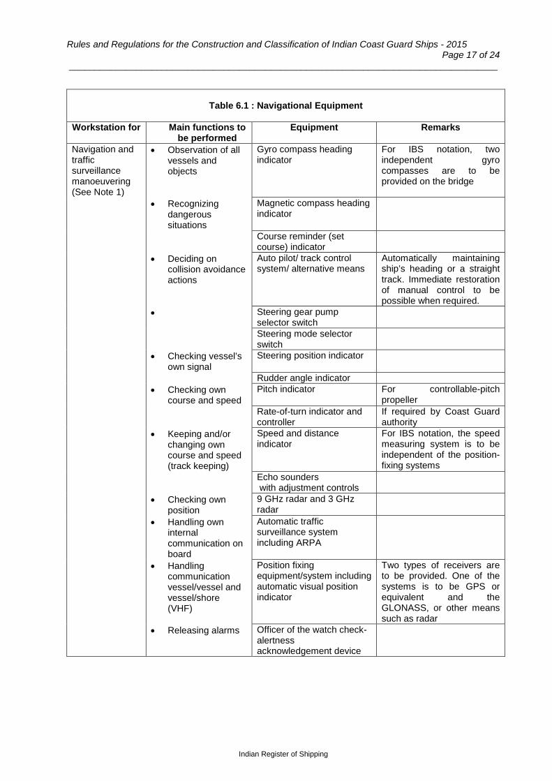
Rules and Regulations for the Construction and Classification of Indian Coast Guard Ships - 2015 Page 17 of 24
___________________________________________________________________________________
Table 6.1 : Navigational Equipment
Workstation for Main functions to be performed
Equipment Remarks
Navigation and traffic surveillance manoeuvering (See Note 1)
• Observation of all vessels and objects
Gyro compass heading indicator
For IBS notation, two independent gyro compasses are to be provided on the bridge
• Recognizing dangerous situations
Magnetic compass heading indicator
Course reminder (set course) indicator
• Deciding on collision avoidance actions
Auto pilot/ track control system/ alternative means
Automatically maintaining ship’s heading or a straight track. Immediate restoration of manual control to be possible when required.
• Steering gear pump selector switch
Steering mode selector switch
• Checking vessel’s own signal
Steering position indicator
Rudder angle indicator • Checking own
course and speed Pitch indicator For controllable-pitch
propeller Rate-of-turn indicator and
controller If required by Coast Guard authority
• Keeping and/or changing own course and speed (track keeping)
Speed and distance indicator
For IBS notation, the speed measuring system is to be independent of the position-fixing systems
Echo sounders with adjustment controls
• Checking own position
9 GHz radar and 3 GHz radar
• Handling own internal communication on board
Automatic traffic surveillance system including ARPA
• Handling communication vessel/vessel and vessel/shore (VHF)
Position fixing equipment/system including automatic visual position indicator
Two types of receivers are to be provided. One of the systems is to be GPS or equivalent and the GLONASS, or other means such as radar
• Releasing alarms Officer of the watch check-alertness acknowledgement device
Indian Register of Shipping
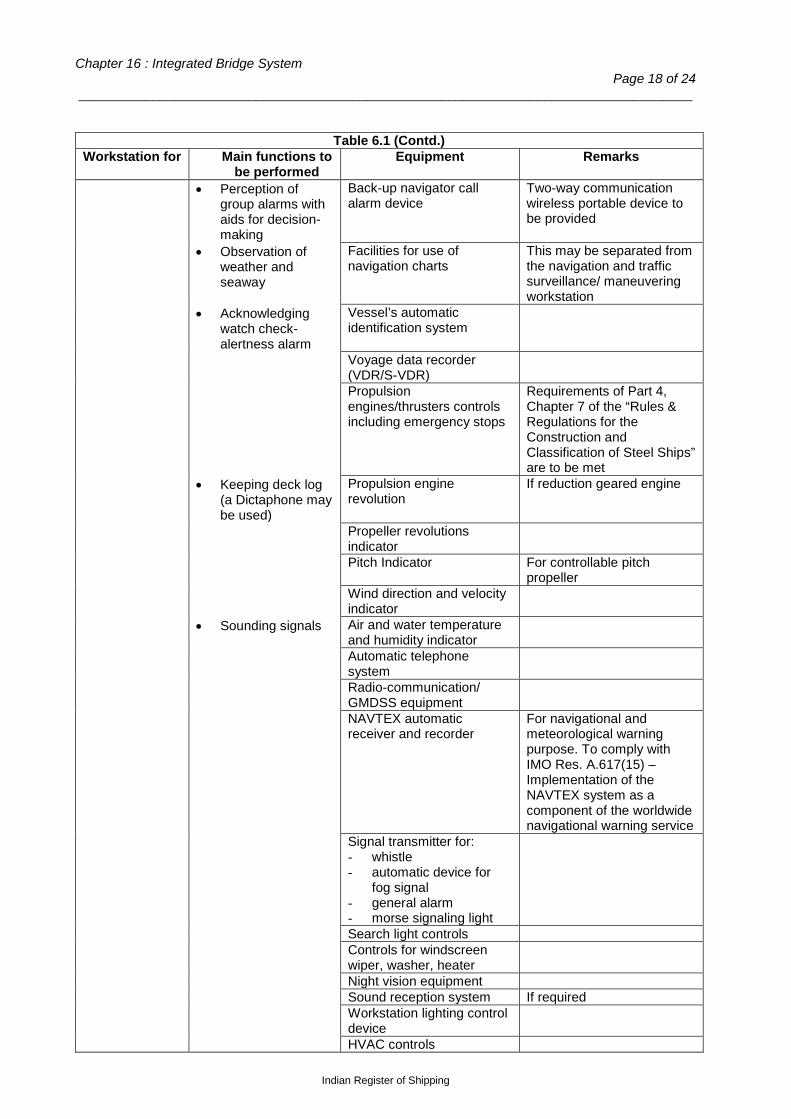
Chapter 16 : Integrated Bridge System Page 18 of 24
___________________________________________________________________________________
Table 6.1 (Contd.) Workstation for Main functions to
be performed Equipment Remarks
• Perception of group alarms with aids for decision-making
Back-up navigator call alarm device
Two-way communication wireless portable device to be provided
• Observation of weather and seaway
Facilities for use of navigation charts
This may be separated from the navigation and traffic surveillance/ maneuvering workstation
• Acknowledging watch check-alertness alarm
Vessel’s automatic identification system
Voyage data recorder (VDR/S-VDR)
Propulsion engines/thrusters controls including emergency stops
Requirements of Part 4, Chapter 7 of the “Rules & Regulations for the Construction and Classification of Steel Ships” are to be met
• Keeping deck log (a Dictaphone may be used)
Propulsion engine revolution
If reduction geared engine
Propeller revolutions indicator
Pitch Indicator For controllable pitch propeller
Wind direction and velocity indicator
• Sounding signals Air and water temperature and humidity indicator
Automatic telephone system
Radio-communication/ GMDSS equipment
NAVTEX automatic receiver and recorder
For navigational and meteorological warning purpose. To comply with IMO Res. A.617(15) – Implementation of the NAVTEX system as a component of the worldwide navigational warning service
Signal transmitter for: - whistle - automatic device for
fog signal - general alarm - morse signaling light
Search light controls Controls for windscreen
wiper, washer, heater
Night vision equipment Sound reception system If required Workstation lighting control
device
HVAC controls
Indian Register of Shipping
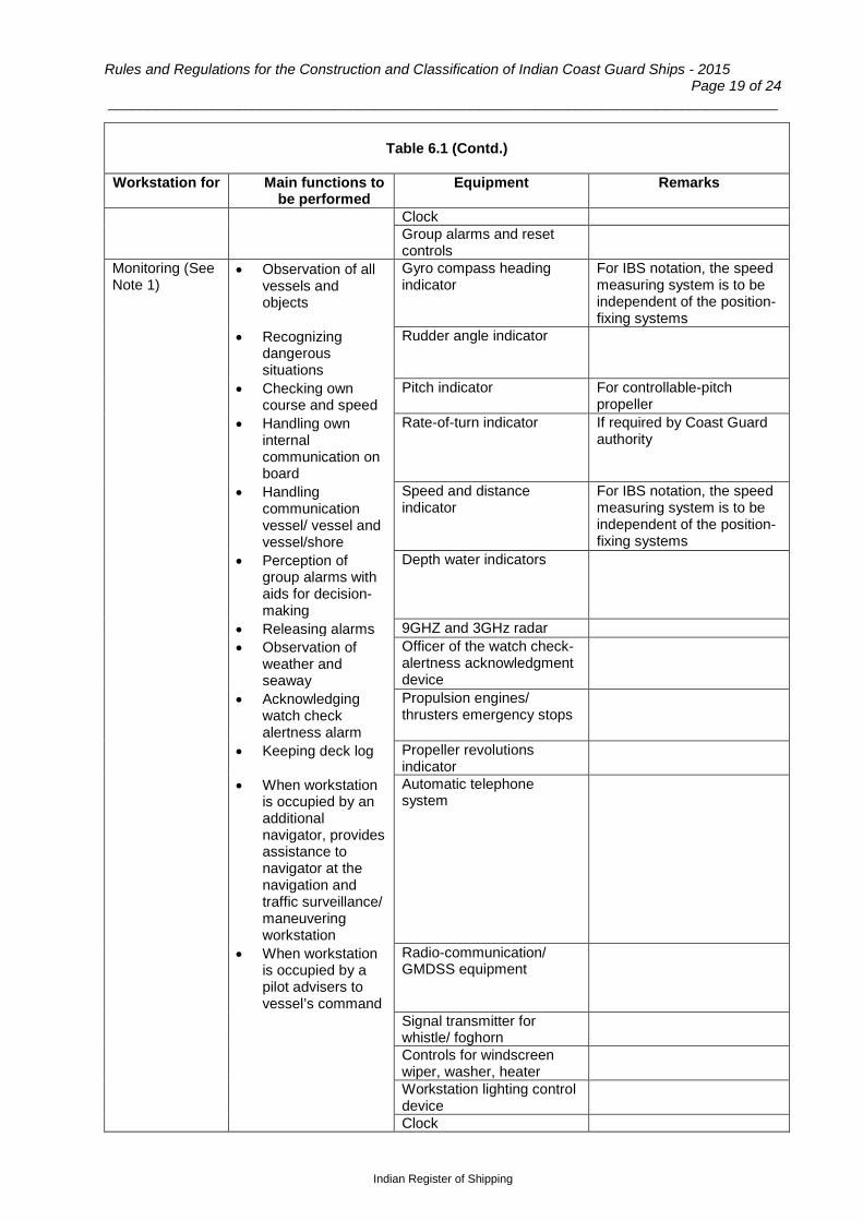
Rules and Regulations for the Construction and Classification of Indian Coast Guard Ships - 2015 Page 19 of 24
___________________________________________________________________________________
Table 6.1 (Contd.)
Workstation for Main functions to
be performed Equipment Remarks
Clock Group alarms and reset
controls
Monitoring (See Note 1)
• Observation of all vessels and objects
Gyro compass heading indicator
For IBS notation, the speed measuring system is to be independent of the position-fixing systems
• Recognizing dangerous situations
Rudder angle indicator
• Checking own course and speed
Pitch indicator For controllable-pitch propeller
• Handling own internal communication on board
Rate-of-turn indicator If required by Coast Guard authority
• Handling communication vessel/ vessel and vessel/shore
Speed and distance indicator
For IBS notation, the speed measuring system is to be independent of the position-fixing systems
• Perception of group alarms with aids for decision-making
Depth water indicators
• Releasing alarms 9GHZ and 3GHz radar • Observation of
weather and seaway
Officer of the watch check-alertness acknowledgment device
• Acknowledging watch check alertness alarm
Propulsion engines/ thrusters emergency stops
• Keeping deck log Propeller revolutions indicator
• When workstation is occupied by an additional navigator, provides assistance to navigator at the navigation and traffic surveillance/ maneuvering workstation
Automatic telephone system
• When workstation is occupied by a pilot advisers to vessel’s command
Radio-communication/ GMDSS equipment
Signal transmitter for whistle/ foghorn
Controls for windscreen wiper, washer, heater
Workstation lighting control device
Clock
Indian Register of Shipping
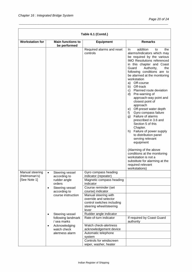
Chapter 16 : Integrated Bridge System Page 20 of 24
___________________________________________________________________________________
Table 6.1 (Contd.)
Workstation for Main functions to
be performed Equipment Remarks
Required alarms and reset controls
In addition to the alarms/indicators which may be required by the various IMO Resolutions referenced in this chapter and Coast Guard Authority, the following conditions are to be alarmed at the monitoring workstation a) Off-course b) Off-track c) Planned route deviation d) Pre-warning of
approach-way point and closest point of approach
e) Off-preset water depth f) Gyro compass failure g) Failure of alarms
prescribed in 3.6 and Section 5 of this Chapter.
h) Failure of power supply to distribution panel serving relevant equipment
(Alarming of the above conditions at the monitoring workstation is not a substitute for alarming at the required relevant workstations)
Manual steering (Helmsman’s) [See Note 1]
• Steering vessel according to rudder angle orders
Gyro compass heading indicator (repeater)
Magnetic compass heading indicator
• Steering vessel according to course instruction
Course reminder (set course) indicator
Manual steering with override and selector control switches including steering wheel/steering lever
• Steering vessel following landmark / sea marks
Rudder angle indicator Rate-of-turn indicator If required by Coast Guard
authority • Acknowledging
watch check alertness alarm
Watch check-alertness acknowledgement device
Automatic telephone system
Controls for windscreen wiper, washer, heater
Indian Register of Shipping

Rules and Regulations for the Construction and Classification of Indian Coast Guard Ships - 2015 Page 21 of 24
___________________________________________________________________________________
Table 6.1 (Contd.)
Workstation for Main functions to be performed
Equipment Remarks
Docking (Bridge wings)
• Giving instructions, performing and controlling change of course
Gyro compass heading indicator
Steering position selector switch
• Giving instructions, performing and controlling change of speed
Rudder controls
• Giving instructions, performing and controlling change of thruster
Rudder angle indicator
• Handling communication with maneuvering stations
Pitch indicator For controllable pitch propeller
Rate-of-turn indicator If required by Coast Guard authority
Propulsion engines/ thrusters controls
• Handling communication with tugs, pilot boat
Propulsion engine revolution
If reduction geared engine
Propeller revolutions indicator
• Watching water surface along vessel’s side
Lateral thrust and lateral movement of vessel, indicator
If thrusters are fitted
Longitudinal movement of vessel, indicator
• Releasing signals Wind direction and velocity indicator
• Acknowledging watch check alertness alarm
Echo sounder Officer of the watch check-
alertness acknowledgement device
Whistle controls Search light and Morse
lamp controls
Automatic telephone system
Radio-communication/ GMDSS equipment
Workstation lighting control device
Centralized Bridge
As listed in 1.2 Equipment required for the navigation and traffic surveillance / maneuvering and monitoring workstations
Central alarm panel ECDIS
Indian Register of Shipping

Chapter 16 : Integrated Bridge System Page 22 of 24
___________________________________________________________________________________
Table 6.1 (Contd.)
Workstation for Main functions to be performed
Equipment Remarks
Route Planning Determination of favourable course and optimum speed, taking into account weather conditions, current, etc. and route planning
ECDIS including navigation planning station
Giving instructions as to the course and speed
Route planning devices
Calculation of tidal data
Chart table
Handling nautical records, documents, publications
Position-fixing receiver
Handling weather reports
Retaining device for drawing triangles, dividers, magnifying lens, pencils, etc.
Determination of documentation of position in case of conventional operation
Weather chart plotter
Control of rate and error of chronometer, deviation, radio deviation, documentation of same
Main clock
Keeping deck log Chronometer with receiving facility for time signals
External communication for planning operation using the chart
Radio direction finder Log, including distance indicator, course plotter
Officer of the watch check-alertness acknowledgement device
Barograph Command printer Automatic telephone system
Acknowledging watch check alertness alarm
Echo sounder
Officer of the watch check-alertness acknowledgement device
Whistle controls Search light and Morse lamp
controls
Automatic telephone system Radio-communication/
GMDSS equipment
Workstation lighting control device
Indian Register of Shipping

Rules and Regulations for the Construction and Classification of Indian Coast Guard Ships - 2015 Page 23 of 24
___________________________________________________________________________________
Table 6.1 (Contd.) Note:
1) As the navigation and traffic surveillance / maneuvering, monitoring and manual steering workstations are functionally interrelated and usually installed in close proximity from each other, consideration will be given to the omission of duplicate equipment required at each of the aforementioned workstations.
Section 7
Bridge Navigational Watch Alarm System
7.1 The requirements complying with the IMO performance standards for a bridge navigational watch alarm system (BNWAS) and approved by the Coast Guard Authority is to be provided to monitor the well-being and awareness of the watchkeeper. The system is not to cause undue interference with the performance of bridge functions. 7.2 The BNWAS safety system is to automatically become operational whenever the ships heading or track control system is activated. 7.3 The system is to be such that, at a predetermined time, the watchkeeper receives warning that he must indicate his well-being by accepting the warning. 7.4 The time interval between warnings is to be adjustable upto a maximum of 12 minutes. 7.5 It is to be possible to acknowledge the warning at the navigation workstation and at other appropriate locations on the bridge where an effective look-out may be kept. Acknowledgement of any alarm is automatically to reset the time interval between warnings. Manual adjustment of controls may also be used for this purpose. 7.6 Visual warning indications are to be visible and audible warning indications are to be audible, from all operational positions on the bridge where the watchkeeper may reasonably be expected to be stationed. The colour of visual indicators is not to impair night vision. 7.7 In the event that the watchkeeper fails to respond and accept the warning or if any alarm has not been acknowledged on the bridge, within a period of 30 seconds, the system is to immediately initiate a watch alarm to warn the Master and the appointed backup navigator through a fixed installation. 7.8 In the event that the watch alarm is not acknowledged, the system is to initiate the watch alarm at the locations of further crew members capable of taking corrective actions following a time delay sufficient to allow the Master or backup navigator to reach the bridge. The time interval is to be adjustable between 90 seconds upto a maximum of 3 minutes. In ships, other than passenger ships, the watch alarms to warn the further crew members may be initiated at the same time as the watch alarm to warn the Master and backup navigator. 7.9 The watch alarms which sound in the locations of the Master, officers and further crew members capable of taking corrective action should be easily identifiable by its sound and should indicate urgency. The volume of this alarm should be sufficient for it to be heard throughout the locations above and to wake sleeping persons. 7.10 Manual initiation of the watch alarm from the bridge is to be possible at any time. 7.11 The system is to be designed and arranged such that only the ship’s Master has access for enabling and disabling it and setting the appropriate intervals, so as to prevent accidental or unauthorized operation, e.g. removing the fuses or keeping the acknowledgement button permanently depressed either accidentally or deliberately.
Indian Register of Shipping

Chapter 16 : Integrated Bridge System Page 24 of 24
___________________________________________________________________________________ 7.12 The fixed installation is to be connected to the Master’s and navigating officers’ cabins, offices, mess and public rooms. 7.13 Acknowledgement of the watch alarm is only to be possible on the bridge. 7.14 If, depending upon the shipboard work organization, the backup navigator may attend locations not connected to the alarm transfer system, a wireless portable device is to be provided enabling both the transfer of alarms and two-way speech communication with the bridge. An audible warning from the portable device is to be provided in the event of loss of the wireless link with the bridge. Alternative arrangements will be considered. 7.15 Failure of the watch alarm system is to activate an audible and visual alarm at the centralized alarm system.
Section 8
Tests and Trials
8.1 General 8.1.1 The tests to be carried out as indicated in this section are intended to supplement and not to replace the testing of parts that is required to meet the relevant IMO performance standards. The tests are intended to ensure that when the parts are integrated there is no degradation of their individual functionality. 8.1.2 In all instances the performance standards for parts will form the minimum test requirement for an integrated system. 8.1.3 During trials, navigational equipment and systems are to be tested to the satisfaction of the attending surveyor in accordance with the test program. The test program is to include following systems as minimum:
a) Course information system b) Automatic steering system c) Speed measuring system d) Depth measuring system e) Radar system f) Automatic traffic surveillance system g) Position fixing system h) Watch monitoring and alarm transfer system i) Route planning system j) Vessel’s automatic identification system k) Sound reception in bridge , if fitted l) Radio communication system m) Centralised bridge workstation provided to enable the navigator to perform necessary
navigational, monitoring/alarm and communication functions as required for IBS. 8.1.4 The trial program is to include test details of ECDIS and IBS. The system is to be tested to verify that failure of one sub system does not affect any other sub system. In case of failure of integrated navigational system, it is to be possible to operate the primary navigational equipment / systems functions independently.
End of Chapter
Indian Register of Shipping

Rules and Regulations for the Construction and Classification of Indian Coast Guard Ships - 2015 Page 1 of 14
___________________________________________________________________________________
Chapter 17
Dynamic Positioning Systems
Contents Section
1 General
2 Thruster System
3 Power Systems
4 DP Control System
5 Tests and Trials
Section 1
General
1.1 Scope, application 1.1.1 The requirements of this Chapter apply to ships installed with dynamic positioning systems and are in addition to those applicable in other Chapters of these Rules. 1.1.2 A ship provided with a dynamic positioning system in accordance with these Rules will be eligible for an appropriate class notation in accordance with Table 1.3.9. 1.1.3 Requirements additional to these Rules may be imposed by the Coast Guard Authority. 1.1.4 These rules specify design criteria, necessary equipment, tests and documentation requirements for dynamic positioning systems to reduce risk to personnel, the vessel, other vessels or structures and the environment while performing operations under dynamic positioning control. 1.2 Definitions 1.2.1 Dynamically positioned vessel means a vessel which automatically maintains its position (fixed location or predetermined track) by means of thruster force. 1.2.2 Dynamic positioning system means the complete installation necessary for dynamically positioning a vessel, comprising of the following sub-systems:
a) Power system, b) Thruster system, c) DP-control system, and d) Independent joystick system.
1.2.3 Position/ heading keeping means maintaining a desired position/ heading within the normal excursions of the control systems and environmental conditions. 1.2.4 Power system means all components and systems necessary to supply the DP-system with power. The power system includes:
a) Prime movers with necessary auxiliary systems including piping b) Generators
Indian Register of Shipping
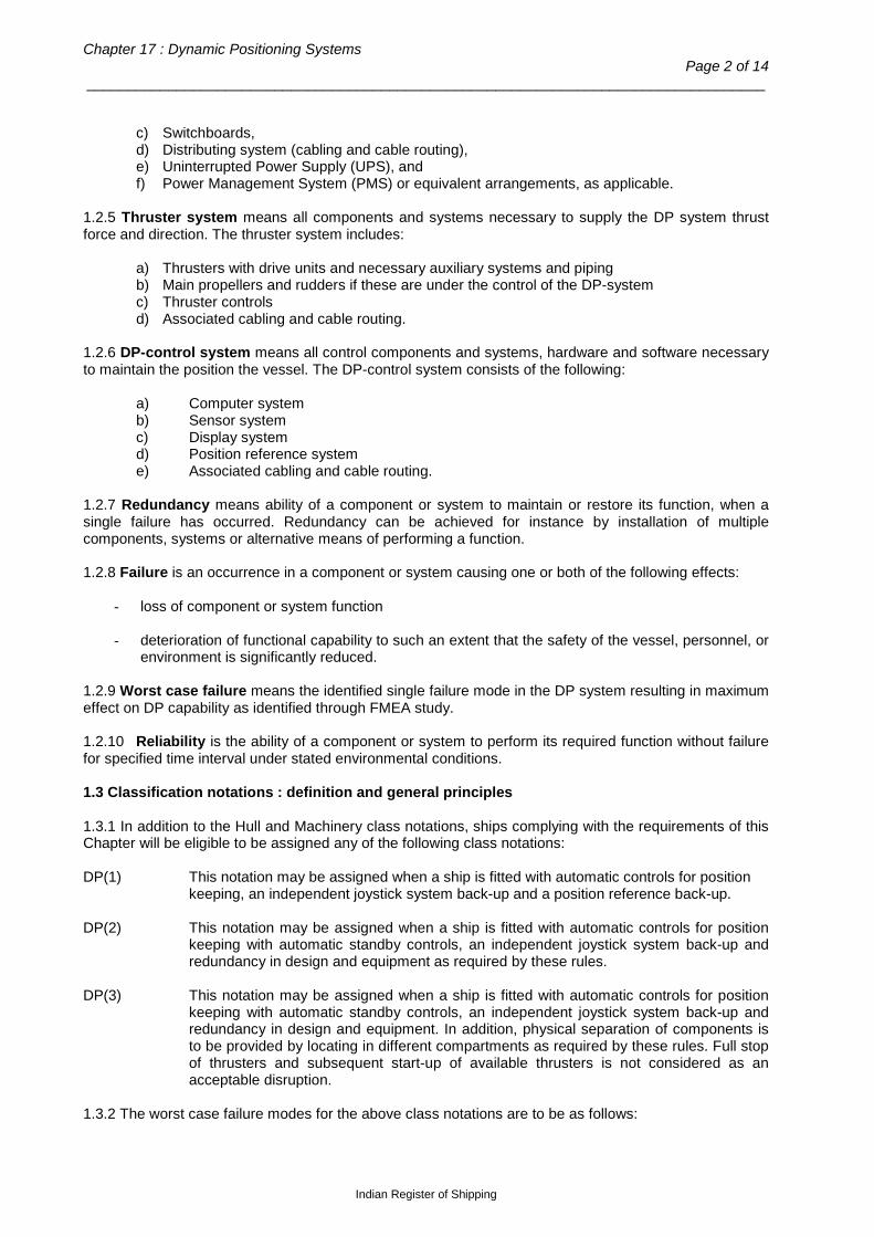
Chapter 17 : Dynamic Positioning Systems Page 2 of 14
___________________________________________________________________________________
c) Switchboards, d) Distributing system (cabling and cable routing), e) Uninterrupted Power Supply (UPS), and f) Power Management System (PMS) or equivalent arrangements, as applicable.
1.2.5 Thruster system means all components and systems necessary to supply the DP system thrust force and direction. The thruster system includes:
a) Thrusters with drive units and necessary auxiliary systems and piping b) Main propellers and rudders if these are under the control of the DP-system c) Thruster controls d) Associated cabling and cable routing.
1.2.6 DP-control system means all control components and systems, hardware and software necessary to maintain the position the vessel. The DP-control system consists of the following:
a) Computer system b) Sensor system c) Display system d) Position reference system e) Associated cabling and cable routing.
1.2.7 Redundancy means ability of a component or system to maintain or restore its function, when a single failure has occurred. Redundancy can be achieved for instance by installation of multiple components, systems or alternative means of performing a function. 1.2.8 Failure is an occurrence in a component or system causing one or both of the following effects:
- loss of component or system function - deterioration of functional capability to such an extent that the safety of the vessel, personnel, or
environment is significantly reduced. 1.2.9 Worst case failure means the identified single failure mode in the DP system resulting in maximum effect on DP capability as identified through FMEA study. 1.2.10 Reliability is the ability of a component or system to perform its required function without failure for specified time interval under stated environmental conditions. 1.3 Classification notations : definition and general principles 1.3.1 In addition to the Hull and Machinery class notations, ships complying with the requirements of this Chapter will be eligible to be assigned any of the following class notations: DP(1) This notation may be assigned when a ship is fitted with automatic controls for position
keeping, an independent joystick system back-up and a position reference back-up. DP(2) This notation may be assigned when a ship is fitted with automatic controls for position
keeping with automatic standby controls, an independent joystick system back-up and redundancy in design and equipment as required by these rules.
DP(3) This notation may be assigned when a ship is fitted with automatic controls for position
keeping with automatic standby controls, an independent joystick system back-up and redundancy in design and equipment. In addition, physical separation of components is to be provided by locating in different compartments as required by these rules. Full stop of thrusters and subsequent start-up of available thrusters is not considered as an acceptable disruption.
1.3.2 The worst case failure modes for the above class notations are to be as follows:
Indian Register of Shipping

Rules and Regulations for the Construction and Classification of Indian Coast Guard Ships - 2015 Page 3 of 14
___________________________________________________________________________________
1.3.2.1 For notation DP(1), loss of position may occur in the event of a single fault. 1.3.2.2 For notation DP(2), a loss of position is not to occur in the event of a single fault in any active
component or system. Normally, static components will not be considered to fail where adequate protection from damage is demonstrated and properly documented with respect to protection and reliability. Single failure criteria for DP(2) include:
a) Failure of any active component or system (generators, thrusters, switchboards including the
short circuit of switchboard bus bars, remote controlled valves, coolers, filters etc.) b) Fault in any normally static component (cables, pipes, manual valves etc) which is not
properly documented with respect to protection c) A single inadvertent act if such an act is reasonably probable d) Systematic failures or faults that can be hidden until a new fault appears e) Automatic interventions caused by external events, when found relevant (e.g. automatic
action upon detection of gas).
1.3.2.3 For notation DP(3), loss of position is not to occur after any of the following failures in addition to 1.3.2.2 above:
a) Fault in any normally static component in the system b) Failure to all components in any watertight compartment, from fire or flooding c) Failure to all components in any fire sub-division, from fire or flooding.
1.3.3 Based on the failure definitions in 1.3.2, the worst case failure is to be determined with the help of FMEA and used as the criteria for consequence analysis. Requirement for failures to be considered are summarized in Table 1.3.3.
Table 1.3.3 : Failures to be considered for various class notations
Notation Position keeping criterion
FMEA required
Failures to be considered
Static components
Active components
Inadvertent acts
Hidden failure
Failure of all components
in a watertight
compartment / fire
subdivision due to fire or
flooding DP1 Loss of
position may occur after single failure
- - - - - -
DP2 Loss of position is not to occur after single failure
Yes Yes1 Yes Yes Yes No
DP3 Loss of position not to occur after single failure including fire / flooding in one compartment
Yes Yes Yes Yes Yes Yes
Note 1 : Not required if the static component (cables, pipes, manual vales etc.) is properly documented with respect to protection.
Indian Register of Shipping

Chapter 17 : Dynamic Positioning Systems Page 4 of 14
___________________________________________________________________________________
The objective of FMEA is to provide a comprehensive, systematic and documented analysis to establish the significant failure modes with regards to position keeping and demonstrate that the vessel maintains position in the event of single failure. Essentially the FMEA is to
- Breakdown the DP system into functional blocks and function of each block is to be described - Identify potential failure modes and their causes
- Evaluate effect on the system for each failure mode
- Identify measures for eliminating and reducing the associated risks
- Identify the trials required to prove the conclusion
- Provide information to operators on system limitations and capabilities.
1.3.4 In order to meet the failure criteria, redundancy of components will normally be necessary as follows:
a) For class notation DP(2), redundancy of all active components;
b) For class notation DP(3), redundancy of all components and physical separation of the components by A-60 class fire divisions, watertight below the damage control deck (maximum possible separation of sensors above deck).
1.3.5 For class notation DP(3), non-redundant connections between otherwise redundant and separated systems may be accepted provided that it gives clear safety advantages and their reliability can be demonstrated and documented to the satisfaction of IRS. Such connections are to be kept to the absolute minimum and made to fail to the safest condition. Failure in one system is not to transfer to the other redundant system. 1.3.6 Redundant components and systems are to be immediately available. The transfer to redundant component or system is to be automatic as far as possible, and the operator intervention is to be kept to a minimum. The transfer should be smooth and within the specified limits of the operation. 1.3.7 For class notation DP(3), cables for redundant equipment or systems are not to be routed together through the same compartments. Where this is unavoidable, such cables may be run in independent cable ducts of A-60 class. Cable connection boxes are not allowed in such ducts. On open deck, cables in separate pipes that are separately routed may be accepted. Suitable means are to be provided to keep the ambient temperature inside of an A-60 cable duct within maximum temperature for the cables, when necessary, taking into account the temperature rise of cables under full power. 1.3.8 For class notation DP(3), redundant piping systems ( e.g. fuel oil, lubrication oil, cooling water, hydraulic oil, pneumatic etc) are not to be routed together through the same compartments. Where this is unavoidable, such pipes may be run together in ducts of A-60 class. Redundant fuel oil supply systems are to be arranged with separate dedicated service tanks. 1.3.9 The requirements for various class notations in these rules are considered to satisfy the equipment classes in IMO guidelines for vessels with dynamic positioning systems (MSC Circ.645) as noted in Table 1.3.9.
Indian Register of Shipping

Rules and Regulations for the Construction and Classification of Indian Coast Guard Ships - 2015 Page 5 of 14
___________________________________________________________________________________
Table 1.3.9 : Correlation with IMO equipment classes
IRS Class notation IMO equipment class
DP(1) Equipment Class 1 DP(2) Equipment Class 2 DP(3) Equipment Class 3
1.4 Summary of requirements for various class notations 1.4.1 The basic requirements for systems and equipment to be provided for various class notations are summarized in Table 1.4.1. The detailed requirements for thrusters, power systems and DP-control systems are given in Sections 2, 3 and 4 of this Chapter.
Table 1.4.1 : Requirements for various class notations
Item Requirement for class notation:
DP(1) DP(2) DP(3) 1. Thrusters: a) Arrangement No redundancy Redundant Redundant and in separate
compartments b) Manual single lever control of individual thruster
yes yes yes
2. Power systems:
a) Electrical power generation and distribution systems
No redundancy Redundancy in design
Redundancy in design and physical separation by A-60 divisions in separate compartments
b) Bus tie breakers
no yes yes
c) Main Switchboard (MSB) yes yes yes d) Power Management System (PMS) or equivalent arrangements
no yes yes
3. DP control system 1): a) Computer systems for automatic control
1 2 2 plus one additional system in back-up control station
b) Consequence analysis
no yes yes
c) Independent common joystick control with manual/ automatic heading control
yes yes yes
4. Position reference systems 2)
2 3 3, of which one system is in back-up control station
5. External sensors: a) Wind 1 2 2, of which one is connected to
back-up control station b) Gyro Compass 1 3 3, of which one in back-up
control station c) Vertical reference system 1 3 3, of which one in back-up
control station 6. UPS 1 2 2 plus one in back-up control
station
Indian Register of Shipping
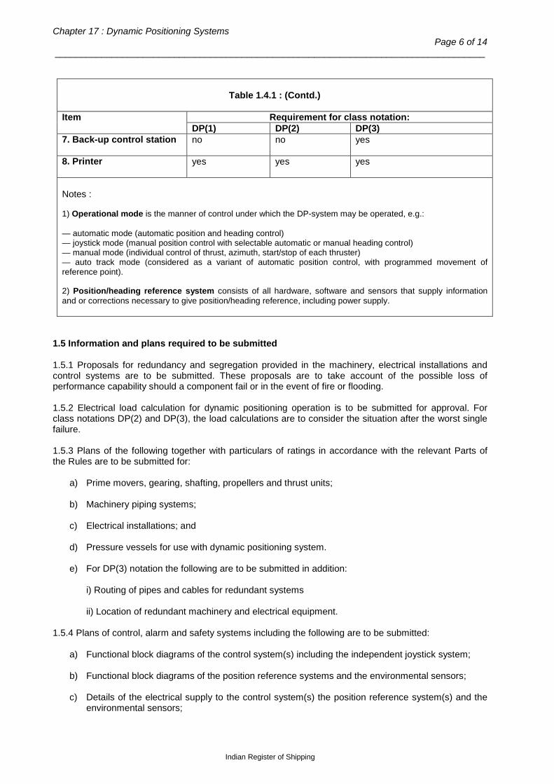
Chapter 17 : Dynamic Positioning Systems Page 6 of 14
___________________________________________________________________________________
Table 1.4.1 : (Contd.)
Item Requirement for class notation:
DP(1) DP(2) DP(3) 7. Back-up control station
no no yes
8. Printer
yes yes yes
Notes : 1) Operational mode is the manner of control under which the DP-system may be operated, e.g.: — automatic mode (automatic position and heading control) — joystick mode (manual position control with selectable automatic or manual heading control) — manual mode (individual control of thrust, azimuth, start/stop of each thruster) — auto track mode (considered as a variant of automatic position control, with programmed movement of reference point). 2) Position/heading reference system consists of all hardware, software and sensors that supply information and or corrections necessary to give position/heading reference, including power supply.
1.5 Information and plans required to be submitted 1.5.1 Proposals for redundancy and segregation provided in the machinery, electrical installations and control systems are to be submitted. These proposals are to take account of the possible loss of performance capability should a component fail or in the event of fire or flooding. 1.5.2 Electrical load calculation for dynamic positioning operation is to be submitted for approval. For class notations DP(2) and DP(3), the load calculations are to consider the situation after the worst single failure. 1.5.3 Plans of the following together with particulars of ratings in accordance with the relevant Parts of the Rules are to be submitted for:
a) Prime movers, gearing, shafting, propellers and thrust units; b) Machinery piping systems; c) Electrical installations; and d) Pressure vessels for use with dynamic positioning system.
e) For DP(3) notation the following are to be submitted in addition:
i) Routing of pipes and cables for redundant systems ii) Location of redundant machinery and electrical equipment.
1.5.4 Plans of control, alarm and safety systems including the following are to be submitted:
a) Functional block diagrams of the control system(s) including the independent joystick system; b) Functional block diagrams of the position reference systems and the environmental sensors; c) Details of the electrical supply to the control system(s) the position reference system(s) and the
environmental sensors;
Indian Register of Shipping

Rules and Regulations for the Construction and Classification of Indian Coast Guard Ships - 2015 Page 7 of 14
___________________________________________________________________________________
d) Details of the monitoring functions of the controllers, sensors and reference system together with a description of the monitoring functions;
e) List of equipment with identification of the manufacturer, type and model; f) Details of the overall alarm system linking the centralized control station, subsidiary control
stations, relevant machinery spaces and operating areas; g) Details of the control stations, e.g. control panels and consoles, including the location of the
control stations; h) Test schedules which are to include the methods of testing and the test facilities provided; and i) Failure Modes and Effects Analysis (F.M.E.A.) in the case of notations DP(2) and DP(3).
1.5.5 Operation manuals, including details of the dynamic positioning system operation, installation of equipment, maintenance and fault finding procedures together with a section on the procedure to be adopted in emergency are to be submitted. A copy of the manual is to be placed on board the ship. 1.5.6 Performance capability evaluation report of the DP system for position keeping ability in the specified operating environmental conditions is to be submitted. This is to include a diagrammatic representation (DP capability Plot) of the limiting wind speeds and direction for effective DP operation, considering wave and current loads also acting simultaneously. A copy of the performance capability evaluation report is to be placed on board the ship. 1.6 Performance capability of the DP system 1.6.1 The performance capability of the dynamic positioning system to provide sufficient thruster forces and moments for maintaining position and heading in specified environmental conditions is to be evaluated. The wind, wave and current conditions in a specified area are to be considered for this purpose. 1.6.2 A performance capability rating may be assigned by IRS for the DP system, if requested. The rating would indicate the percentage of time that environmental forces in a specified area may be withstood by the system. 1.6.3 The following parameters are considered in the evaluation of the performance capability rating:
a) Thruster forces
b) Wind loads on the ship c) Wave drift loads on the ship d) Current loads on the ship.
Indian Register of Shipping
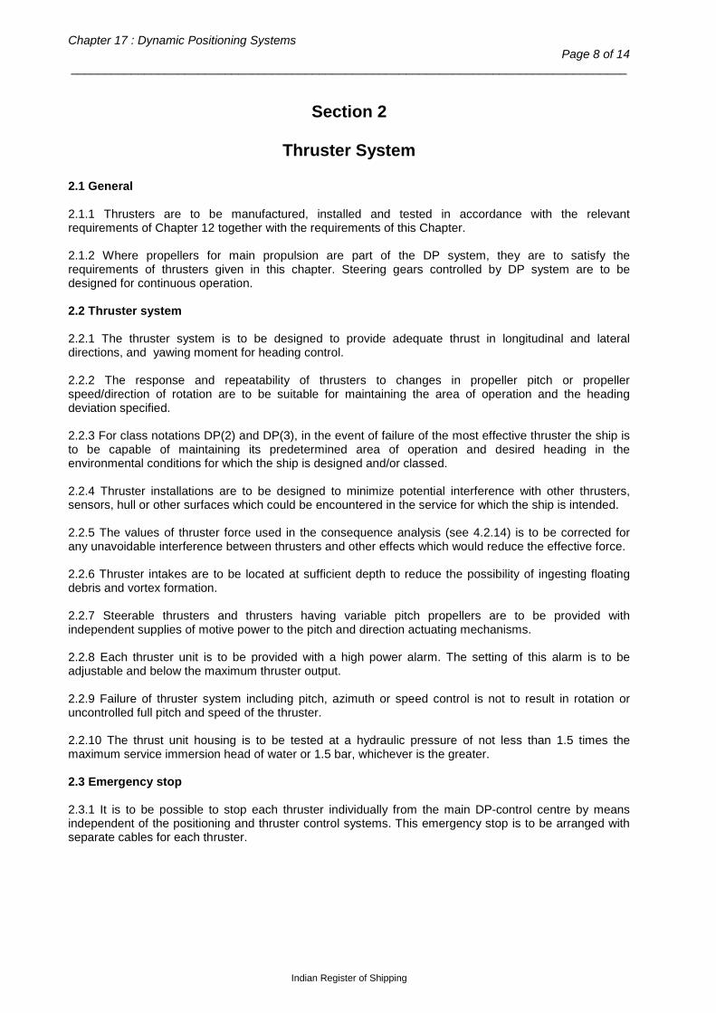
Chapter 17 : Dynamic Positioning Systems Page 8 of 14
___________________________________________________________________________________
Section 2
Thruster System
2.1 General 2.1.1 Thrusters are to be manufactured, installed and tested in accordance with the relevant requirements of Chapter 12 together with the requirements of this Chapter. 2.1.2 Where propellers for main propulsion are part of the DP system, they are to satisfy the requirements of thrusters given in this chapter. Steering gears controlled by DP system are to be designed for continuous operation. 2.2 Thruster system 2.2.1 The thruster system is to be designed to provide adequate thrust in longitudinal and lateral directions, and yawing moment for heading control. 2.2.2 The response and repeatability of thrusters to changes in propeller pitch or propeller speed/direction of rotation are to be suitable for maintaining the area of operation and the heading deviation specified. 2.2.3 For class notations DP(2) and DP(3), in the event of failure of the most effective thruster the ship is to be capable of maintaining its predetermined area of operation and desired heading in the environmental conditions for which the ship is designed and/or classed. 2.2.4 Thruster installations are to be designed to minimize potential interference with other thrusters, sensors, hull or other surfaces which could be encountered in the service for which the ship is intended. 2.2.5 The values of thruster force used in the consequence analysis (see 4.2.14) is to be corrected for any unavoidable interference between thrusters and other effects which would reduce the effective force. 2.2.6 Thruster intakes are to be located at sufficient depth to reduce the possibility of ingesting floating debris and vortex formation. 2.2.7 Steerable thrusters and thrusters having variable pitch propellers are to be provided with independent supplies of motive power to the pitch and direction actuating mechanisms. 2.2.8 Each thruster unit is to be provided with a high power alarm. The setting of this alarm is to be adjustable and below the maximum thruster output. 2.2.9 Failure of thruster system including pitch, azimuth or speed control is not to result in rotation or uncontrolled full pitch and speed of the thruster. 2.2.10 The thrust unit housing is to be tested at a hydraulic pressure of not less than 1.5 times the maximum service immersion head of water or 1.5 bar, whichever is the greater. 2.3 Emergency stop 2.3.1 It is to be possible to stop each thruster individually from the main DP-control centre by means independent of the positioning and thruster control systems. This emergency stop is to be arranged with separate cables for each thruster.
Indian Register of Shipping

Rules and Regulations for the Construction and Classification of Indian Coast Guard Ships - 2015 Page 9 of 14
___________________________________________________________________________________
Section 3
Power Systems
3.1 General 3.1.1 The power systems are to be designed, constructed and installed in accordance with the relevant requirements of Chapter 13, together with the requirements of this Chapter. 3.1.2 For class notation DP (2), the power system is to be divided into two or more systems such that in the event of failure of one system, at least one other system will remain in operation. The power system may be run as one system during operation, but should be arranged by bus tie breakers to separate automatically upon failures which could be transferred from one system to another, including overloading and short-circuits. 3.1.3 For class notation DP(3), the power system is to be divided into two or more systems such that in the event of failure of one system, at least one system will remain in operation. The divided power systems are to be located in different spaces separated by A-60 class division. Where the power systems are located below the damage control deck, the separation is also to be watertight. The bus tie breakers are to be open during operations unless equivalent integrity of power operation can be accepted according to 1.3.5. 3.1.4 Means are to be provided in order to prevent overloading of the power plant, e.g. by use of interlocks, thrust limitations or other means. Means are also to be provided to prevent reactive overload. 3.1.5 Generally no restrictions are to be put on the starting intervals of electrical machines. If required, the arrangement is subject to approval in each case. 3.2 Generators 3.2.1 For class notations DP(1), the total generating capacity of the power system is to be not less than the maximum dynamic positioning load together with the maximum auxiliary load. This may be achieved by parallel operation of two or more generating sets provided the requirements of Pt.4 are complied with. 3.2.2 When the electrical power requirements are supplied by one generator set, on loss of power there is to be provision for automatic starting and connection to the switchboard of a standby set and automatic restarting of essential auxiliary services. 3.2.3 Indication of absorbed electrical power and available on-line generating capacity is to be provided at the main dynamic positioning control station. An alarm is to be initiated at the dynamic positioning control station(s) when the total electrical load of all operating thruster units exceeds a preset percentage of the running generator(s) capacity. This alarm is to be adjustable between 50 and 100 per cent of the full load capacity having regard to the number of electrical generators in service. For class notations DP(2) and DP(3), in operating conditions where all the generator sets are not being utilized, provision is to be made for automatic starting, synchronization and load sharing of a non-running generator before the load reaches the alarm level required above. 3.2.4 Means are to be provided to prevent starting of thruster motors until sufficient generating capacity is available. 3.2.5 For class notations DP(2) and DP(3), the power available for position keeping is to be sufficient to maintain the vessel in position after the worst case failure according to 1.3.2. 3.3 Distribution arrangements 3.3.1 Thruster auxiliaries, control computers, reference systems and environmental sensors are to be served by individual circuits. Services that are duplicated are to be separated throughout their length as
Indian Register of Shipping
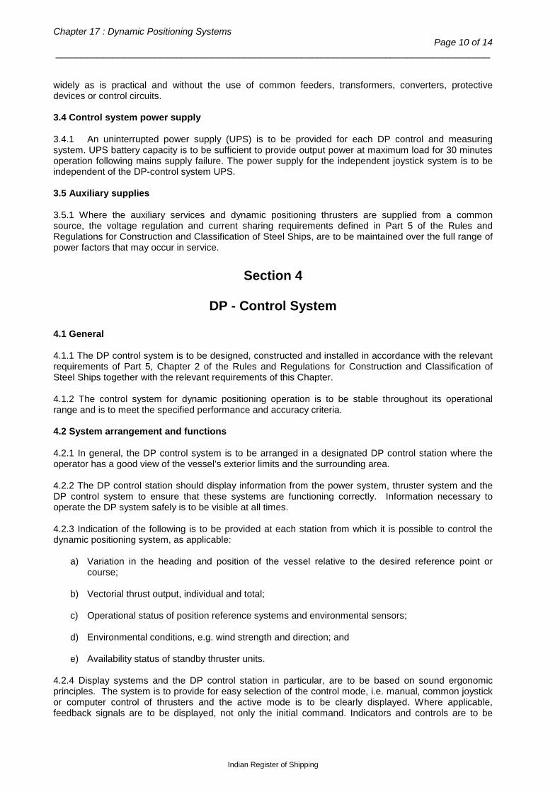
Chapter 17 : Dynamic Positioning Systems Page 10 of 14
___________________________________________________________________________________
widely as is practical and without the use of common feeders, transformers, converters, protective devices or control circuits. 3.4 Control system power supply 3.4.1 An uninterrupted power supply (UPS) is to be provided for each DP control and measuring system. UPS battery capacity is to be sufficient to provide output power at maximum load for 30 minutes operation following mains supply failure. The power supply for the independent joystick system is to be independent of the DP-control system UPS. 3.5 Auxiliary supplies 3.5.1 Where the auxiliary services and dynamic positioning thrusters are supplied from a common source, the voltage regulation and current sharing requirements defined in Part 5 of the Rules and Regulations for Construction and Classification of Steel Ships, are to be maintained over the full range of power factors that may occur in service.
Section 4
DP - Control System
4.1 General 4.1.1 The DP control system is to be designed, constructed and installed in accordance with the relevant requirements of Part 5, Chapter 2 of the Rules and Regulations for Construction and Classification of Steel Ships together with the relevant requirements of this Chapter. 4.1.2 The control system for dynamic positioning operation is to be stable throughout its operational range and is to meet the specified performance and accuracy criteria. 4.2 System arrangement and functions 4.2.1 In general, the DP control system is to be arranged in a designated DP control station where the operator has a good view of the vessel’s exterior limits and the surrounding area. 4.2.2 The DP control station should display information from the power system, thruster system and the DP control system to ensure that these systems are functioning correctly. Information necessary to operate the DP system safely is to be visible at all times. 4.2.3 Indication of the following is to be provided at each station from which it is possible to control the dynamic positioning system, as applicable:
a) Variation in the heading and position of the vessel relative to the desired reference point or course;
b) Vectorial thrust output, individual and total; c) Operational status of position reference systems and environmental sensors; d) Environmental conditions, e.g. wind strength and direction; and e) Availability status of standby thruster units.
4.2.4 Display systems and the DP control station in particular, are to be based on sound ergonomic principles. The system is to provide for easy selection of the control mode, i.e. manual, common joystick or computer control of thrusters and the active mode is to be clearly displayed. Where applicable, feedback signals are to be displayed, not only the initial command. Indicators and controls are to be
Indian Register of Shipping

Rules and Regulations for the Construction and Classification of Indian Coast Guard Ships - 2015 Page 11 of 14
___________________________________________________________________________________
arranged in logical groups, and are to be co-ordinated with the geometry of the vessel, when this is relevant. 4.2.5 At least one computer system for automatic control is to be provided for class notation DP(1). 4.2.6 The range of operation is to be adjustable, but should not exceed the specified limits which are to be based on a percentage of water depth, or if applicable a defined absolute surface movement. Arrangements are to be provided to fix and identify the set point for the area of operation. It is to be possible to individually enter new position and heading set points in automatic control mode. 4.2.7 Alarms and warnings for failures in systems interfaced to and/or controlled by the DP-control system are to be audible and visual. A permanent record of their occurrence and of status changes are to be provided together with any necessary explanations. 4.2.8 The DP control system should prevent failures being transferred from one system to another. The redundant components are to be so arranged that a failure of one component is to be isolated and the other component activated. When combining position reference systems and/or sensors in one unit where more than one function or system can be lost upon one common failure, the consequence to the total system upon such a failure is not to exceed the loss if non-combined installation was adopted. 4.2.9 Manual control of the thrusters is to be possible individually and by a common joystick independent of the DP-control system. Automatic heading control is to be available along with manual joystick control. Any failure causing operator loss of control of the thrusters in the independent joystick control system is to freeze the thrust commands or set the thrust commands to zero. If the failure affects only a limited number of thrusters, the command to these affected thrusters may be set to zero, while keeping the other unaffected thrusters in joystick control. 4.2.10 For class notation DP(2), the DP control system is to consist of at least two independent computer systems. Common facilities such as self-checking routines, data transfer arrangements and plant interfaces are not to be capable of causing failure of both/ all systems. 4.2.11 Redundant computer systems are to be arranged with automatic transfer of control after a detected failure in one of the computer systems. The automatic transfer of control from one computer system to another is to be smooth and within the acceptable limits of the operation. It is not to be possible to automatically or manually select a controller which is not ready to assume command as the active controller. 4.2.12 For class notation DP(3), in addition to the requirements in 4.2.10 above, a back-up control system is to be arranged in a room separated by A-60 class division from the main DP control station. During DP operation, this back-up control system is to be continuously updated by input from the sensors, position reference system, thruster feedback etc, and be ready to take over control. The switch-over of control to the back-up computer is to be manual, situated at the back-up computer and not affected by the failure of the main DP-control system. A backup controller status is to be updated at main controller at regular intervals. An alarm is to be initiated if the back up control system fails or is not ready to take control. The back-up DP-control centre is to be arranged with similar view to the vessel’s exterior limits and the surrounding area as the main DP-control station. 4.2.13 For class notations DP(2) and DP(3), the DP control system is to include a software function, known as ‘consequence analysis’, which continuously verifies that the vessel will remain in position even if the worst-case failure occurs. This analysis is to verify that the thrusters remaining in operation after the worst-case failure can generate the same resultant thruster force and moment as required before the failure. An alarm is to be provided if the occurrence of a worst-case failure is expected to lead to a loss of position due to insufficient thrust for the prevailing environmental conditions. For operations, which will take a long time to safely terminate, the consequence analysis is to include a function to verify the adequacy of thrust and power remaining after worst-case failure based on manual input of weather trend. 4.2.14 When stopped, either by automatic or manual means, the position control system is to set the thrust commands to zero.
Indian Register of Shipping

Chapter 17 : Dynamic Positioning Systems Page 12 of 14
___________________________________________________________________________________
4.2.15 Loss of one or multiple position reference system inputs and/or one or multiple sensor inputs shall not lead to significant change in thrust output. 4.2.16 Upon recovery of position and heading reference input the DP-control system is not to automatically apply the last position or heading set point (set points before loss of input) when this is significantly different from the actual vessel position and/or heading. If any other set point than the actual vessel position and/or heading is applied then it is to be operator chosen. 4.3 Position reference systems and environmental sensors 4.3.1 Position reference systems and environmental sensors are to be provided to ensure that the specified area of operation and heading deviation can be effectively maintained. Sensors are to provide new data with a refresh rate and accuracy suitable for the intended DP operations. 4.3.2 Position reference systems are to incorporate suitable position measurement techniques which may be by means of acoustic devices, radio, radar, inertial navigation, satellite navigation, taut wire or other acceptable means depending on the service conditions for which the ship is intended. 4.3.3 For class notation DP(1), at least two position reference systems are to be provided, each using a different measurement technique. Special consideration may be given to cases where the use of two different measuring techniques would not be practicable during DP operation. In such cases, alternative arrangements may be accepted (for e.g. two DGPS systems). 4.3.4 For class notations DP(2) and DP(3), at least three position reference systems incorporating at least two different measurement techniques are to be provided and simultaneously available to the DP-control system during operation. The position reference systems are to be arranged so that a failure in one system will not render the other systems inoperative. 4.3.5 For class notation DP (3), at least one of the position reference systems is to be connected directly to the back-up control system and separated by A-60 class division from the other position reference systems. 4.3.6 Gyrocompass(es), or equivalent means are to be provided to measure the relative heading of the ship. 4.3.7 Vertical reference sensor(s) are to be provided, if applicable, to measure the pitch and roll of the ship. 4.3.8 Means are to be provided to ascertain the speed and direction of wind, acting on the ship. 4.3.9 For class notation DP(2) or DP(3), at least three sensors each are to be provided for measurement of parameters required by 4.3.6 and 4.3.7 and at least two sensors are to be provided for 4.3.8 above. In the event of a failure, of a reference or environmental sensor the control systems are to continue operating on signals from the remaining sensors without manual intervention. 4.3.10 For class notation DP(3), one of each type of sensors is to be connected directly to the back-up control system and separated by A-60 class division from the other sensors. 4.3.11 Suitable processing and comparative techniques are to be provided to validate the control system inputs from position and other sensors, to ensure the optimum performance of the dynamic positioning system. Abnormal signal errors revealed by the validity checks are to operate alarms. When several systems are combined to provide a mean reference, the mean value used is to not change abruptly by one system being selected or deselected. 4.3.12 The accuracy of the position reference data is generally to be within the following values as a guidance : - a radius of 2% of water depth for bottom-based systems
Indian Register of Shipping

Rules and Regulations for the Construction and Classification of Indian Coast Guard Ships - 2015 Page 13 of 14
___________________________________________________________________________________
- within a radius of 3 [m] for surface-based systems.
4.4 Alarms 4.4.1 The alarms to be presented in the DP-control centre are normally to be limited to functions relevant to DP operation. Alarms are to be provided for the following fault conditions of the control system/ sensors:
a) Control computer system fault; b) Automatic changeover to a standby control computer system. c) Deviation from the predetermined area of operation of the ship; d) Deviation from the predetermined heading limits of the ship; e) Position reference system fault (for each reference system); f) Gyrocompass fault; g) Vertical reference sensor fault; h) Wind sensor fault; i) Taut wire excursion limit; and j) Automatic changeover to a standby position reference system or environmental sensor. k) Failure in the independent joystick control system; l) Loss of charger input power and UPS on bypass power; m) Limit alarms are to be provided for systems, which have defined range limits; n) For DP(2) and DP(3), if the consequence analysis is not completed within 2 minutes then an
alarm is to be initiated; and o) Any failure of a standby position control system or positioning reference system selected is also
to initiate an alarm. 4.4.2 A manually initiated emergency alarm, clearly distinguishable from all other alarms associated with the dynamic positioning system is to be provided at the dynamic positioning control station to warn all relevant personnel in the event of a total loss of dynamic positioning capability. In this respect consideration should be given to additional alarms being provided at locations such as the master's accommodation and operational control stations. 4.5 Internal Communication A two-way voice communication facility is to be provided between the DP-system control centre and the navigation bridge, ECR and relevant operation control centres. The two-way voice communication system is to be supplied by a battery or an uninterruptible power supply as a stand-by power supply sufficient to operate the system for at least 30 minutes.
Section 5
Tests and Trials
5.1 General 5.1.1 Before a new installation (or any alteration or addition to an existing installation) is put into service, trials are to be carried out. These trials are in addition to any acceptance tests which may have been carried out at the manufacturers' works and are to be based on the approved test schedules list as required by 1.5.4. 5.1.2 Functional tests of control and alarm systems of each thruster are to be carried out. All sensors and reference systems are to be tested for satisfactory performance as part of the DP system. 5.1.3 The suitability of the dynamic positioning system is to be demonstrated during DP trials at sea, observing the following:
Indian Register of Shipping

Chapter 17 : Dynamic Positioning Systems Page 14 of 14
___________________________________________________________________________________
a) Response of the system to simulated failures of major items of control and mechanical equipment, including loss of electrical power; to try out switching modes, back-up systems and alarm systems. In case redundancy is based upon change-over of a single stern thruster as described in 1.3.1, then the functionality of the change over mechanism and availability of the thruster after single failure is to be demonstrated at sea-trials.
b) Response of the system under a set of predetermined maneuvers for changing
- Location of area of operation; - Heading of the ship; and
Change of command between the automatic DP-control system, independent joystick system and the individual thruster lever systems are to be demonstrated. c) Continuous operation of the system over a period of four to six hours, including continuous
operation of at least 2 hours during weather conditions such that an average load level on the thrusters of 50% or more is achieved.
5.1.4 All functions of the independent joystick control system are to be tested. 5.1.5 For class notations DP(2) and DP(3), selected tests within each system analysed in the FMEA are to be carried out to verify the conclusions of the FMEA. 5.1.6 Three copies of the dynamic positioning system test schedules, as required by 1.5.4, signed by the Surveyor, the Coast Guard Authority and Shipbuilder are to be provided on completion of the survey. One copy is to be placed on board the vessel and the others to be submitted to IRS and the Coast Guard Authority. 5.1.7 Records and data regarding the performance capability of the dynamic positioning system are to be maintained on board the ship. 5.1.8 During sea trials the offset inputs for each position reference system and relevant sensors in the DP control system are to be verified and demonstrated to the attending surveyor by setting out the offsets on drawings. It is to be verified that these fit with the actual placing of the equipment. 5.1.9 Emergency stop function is to be demonstrated. 5.1.10 For steering gears included under DP control a test is to be carried out verifying that maximum design temperature of actuator and all other steering gear components is not exceeded when the rudder is continuously put over between maximum limits on either side set by the DP-control system, until temperature is stabilized. In this respect, the ambient conditions specified in Pt.4, Ch.1, of the Rules and Regulations for the Construction and Classification of Steel Ships, would be considered. The actual ambient conditions and temperature rise of components are to be noted during trials for evaluation. 5.1.11 The capacity of the UPS battery is to be tested during trials.
End of Chapter
Indian Register of Shipping

Rules and Regulations for the Construction and Classification of Indian Coast Guard Ships - 2015
Page 1 of 3
Annexure - 1
Stability of Monohull Ships
1. Stability criteria in the intact condition (Applicable to all monohull ships of Indian Coast Guard).
1.1 The weather criterion contained in paragraph 3.2 of the Intact Stability Code (Refer to the Code on Intact Stability for all types of ships covered by IMO instruments, adopted by the Organization by Resolution A.749(18), as amended by Resolution MSC.75(69)) shall apply (In applying this criterion, small openings through which progressive flooding cannot take place need not be considered open).
In applying the weather criterion, the value of wind pressure P[N/m2] shall be taken as 0.196(VW)2, where VW = wind speed [knots] corresponding to the worst intended conditions. (Refer Chapter 1, Section 2, Clause 2.6.41 for definition of worst intended condition and Chapter 4, Section 2,2.3.3 for wind speeds corresponding to respective Class Notation.)
The angle of heel due to wind, in applying paragraph 3.2.2.1.2 of the Intact Stability Code, shall not exceed 16° or 80% of the angle of deck-edge immersion (whichever is less). Where the angle of heel due to wind exceeds 10°, efficient non-slip deck surfaces and suitable holding points shall be provided, in accordance with paragraph 2.6.13 of Chapter 4. In applying the weather criterion, account shall also be taken of the roll damping characteristics of individual ship, which may alternatively be derived from model or full-scale tests. 1.2 The area under the righting lever curve (GZ curve) shall not be less than 0.07 [m-rad] upto θ = 15° when the maximum righting lever (GZ) occurs at θ = 15° and 0.055 [m-rad] upto θ = 30° when the maximum righting lever occurs at θ = 30° or above. Where the maximum righting lever occurs at angles of between θ = 15° and θ = 30°, the corresponding area under the righting lever curve shall be:
A = 0.055 + 0.001 (30° - θ max) [m-rad]
where, θ max is the angle of heel, in degrees, at which the righting lever curve reaches its maximum.
1.3 The area under the righting lever curve between θ = 30° and θ = 40° or between θ = 30° and the angle of flooding θF if this angle is less than 40°, shall not be less than 0.03 [m-rad]. (In applying this criterion, small openings through which progressive flooding cannot take place need not be considered open). 1.4 The righting lever GZ shall be at least 0.2 [m] at an angle of heel equal to or greater than 30°. 1.5 The maximum righting lever shall occur at an angle of heel not less than 15°. 1.6 The initial metacentric height GMT shall not be less than 0.15 [m].
Indian Register of Shipping

Annexure 1 : Stability of Monohull Ships
Page 2 of 3
2. Criteria for residual stability after damage 2.1 The stability required in the final condition after damage and after equalization where provided, shall be determined as specified in 2.1.1 to 2.1.4. 2.1.1 The positive residual lever curve shall have a minimum range of 15° beyond the angle of equilibrium. This range may be reduced to a minimum of 10°, in the case where the area under the righting lever curve is that specified in 2.1.2, increased by the ratio:
range15
where the range is expressed in degrees. The range shall be taken as the difference between the equilibrium heel angle and the heel angle at which the residual righting lever subsequently becomes negative or the angle at which progressive flooding occurs, whichever is less. 2.1.2 The area under the righting lever curve shall be at least 0.015 [m-rad], measured from the angle of equilibrium to the lesser of:
a) the angle at which progressive flooding occurs; and b) 27° measured from the upright.
2.1.3 A residual righting lever shall be obtained within the range of positive stability, taking into account the greatest of the following heeling moments:
a) the crowding of all personnel towards one side; b) the launching of all fully loaded davit-launched survival ship on one side; c) due to wind pressure,
as calculated by the formula:
[m].ntdisplaceme
momentheelingGZ 040+=
However, in no case shall this righting lever be less than 0.1 [m]. 2.1.4 For the purpose of calculating the heeling moments referred to in 2.1.3, the following assumptions shall be made: 2.1.4.1 Moments due to crowding of personnel. The following assumptions are to be made:
a) The distribution of personnel is 04 persons per square meter.
b) Each person has a mass of 75 [kg].
c) Vertical centre of gravity of seated persons is 0.3 [m] above seat.
d) Vertical centre of gravity of standing persons is 1.0 [m] above deck.
e) Persons are distributed on available deck areas towards one side of the ship on the decks where assembly stations are located and in such a way that they produce the most adverse heeling moment.
f) Persons assumed to be occupying seats are to be taken as having a vertical centre of gravity corresponding to being seated, with all others standing.
Indian Register of Shipping

Rules and Regulations for the Construction and Classification of Indian Coast Guard Ships - 2015
Page 3 of 3
2.1.4.2 Moments due to launching of all fully loaded davit-launched survival ship on one side:
a) all lifeboats and rescue boats fitted on the side to which the ship has heeled after having sustained damage shall be assumed to be swung out fully loaded and ready for lowering;
b) for lifeboats which are arranged to be launched fully loaded from the stowed position, the
maximum heeling moment during launching shall be taken;
c) a fully loaded davit-launched liferaft attached to each davit on the side to which the ship has heeled after having sustained damage shall be assumed to be swung out ready for lowering;
d) persons not in the life-saving appliances which are swung out shall not provide either
additional heeling or righting moment; and
e) life-saving appliances on the side of the ship opposite to the side to which the ship has heeled shall be assumed to be in a stowed position.
2.1.4.3 Moments due to wind pressure:
a) the wind pressure shall be taken as 0.047(VW)2 [N/m2], where VW = wind speed [knots], corresponding to the worst intended condition. (Refer Chapter 1,Section 2, Clause 2.6.41 for definition of worst intended condition and Chapter 4, Section 2, Clause 2.3.3 for wind speeds corresponding to respective Class Notation.)
b) the area applicable shall be the projected lateral area of the ship above the waterline
corresponding to the intact condition; and
c) the moment arm shall be the vertical distance from a point at one half of the mean draught corresponding to the intact condition to the geometrical centre of the lateral area.
2.2 In intermediate stages of flooding, the maximum righting lever shall be at least 0.05 [m] and the range of positive righting levers shall be at least 7°. In all cases, only one breach in the hull and only one free surface need be assumed.
End Of Chapter
Indian Register of Shipping

Rules and Regulations for the Construction and Classification of Indian Coast Guard Ships - 2015
Page 1 of 4
Annexure - 2
Requirements and Compliance Criteria Related to Operational and Safety Performance
This Annexure applies to monohull type of ship. Tests / trials to evaluate operational safety are to be conducted on the prototype ship of a new design or of a design incorporating new features which may modify the results of a previous testing. The tests / trials are to be carried out to a schedule agreed between the Indian Coast Guard and the Shipbuilder. Where conditions of service warrant additional testing (e.g. low temperature), the Indian Coast Guard / IRS as appropriate, may require further demonstrations. Functional descriptions, technical and system specifications relevant to the understanding and evaluation of ship performance are to be made available by the Shipbuilder. The objective of these tests / trials is to provide essential information and guidance to enable the ship to be operated safely under normal and emergency conditions within the design speed and environmental envelope. The following procedures are outlined as requirements in dealing with verification of ship performance. 1. Performance 1.1 General 1.1.1 The ship is to meet the applicable operational requirements and requirements of this annexure for all extremes of passenger and load configurations for which certification is required. The limiting Sea State related to the different modes of operation or as specified by Indian Coast Guard is to be verified by tests and analyses of a ship of the type for which certification is requested. 1.1.2 Operational control of the ship should be in accordance with procedures established by the shipbuilder for operation in service. Procedures to be established include start procedure, cruise procedures, normal and emergency stop and manoeuvre procedures. 1.1.3 The procedures established under 1.1.2 are to:
.1 demonstrate that normal maneuvers and ship responses to failures are consistent in performance;
.2 use methods or devices that are safe and reliable; and
.3 include allowance for any time lag in the execution of procedures that may reasonably be expected in service.
1.1.4 Procedures required by this annex are to be conducted over water of sufficient depth such that ship performance is not affected. 1.1.5 Tests / trials are to be conducted at minimum practicable weight and additional testing is to be conducted at maximum weight sufficient to establish the need for additional restrictions and for testing to examine the effect of weight. 2. Stopping 2.1 This test is to establish the acceleration experienced when stopping the ship in calm water with no passenger load or cargo load during the following conditions:
.1 normal stop for maximum operational speed;
Indian Register of Shipping

Annexure 2 : Requirements and Compliance Criteria Related to Operational and Safety Performance
Page 2 of 4
.2 emergency stop for maximum operational speed; and
.3 crash stop from maximum operational speed and from any transient mode speed. 2.2 The tests referred to in 2.1.1 and 2.1.2 are to record and document the acceleration values, when control levers are used in accordance to written procedures as given in the ship operating manual or in an automatic mode. 2.3 The test referred to in 2.1.3 is to record and document the accelerations when control levers of automatic modes are used in a manner which will give the highest accelerations. 2.4 Other tests should be repeated during ship turning to establish the need or otherwise to impose any speed-related restrictions during manoeuvres. 3. Cruise performance 3.1 This test is to establish the ship performance and accelerations experienced during cruise modes with no cargo load during the following conditions:
.1 normal operation conditions are those in which the ship will safely cruise at any heading while manually operated, auto-pilot assisted operated or operated with any automatic control system in normal mode; and
.2 worst intended conditions, referred to in Chapter 1, 2.6.46 of these Rules, are those in which it should be possible to maintain safe cruise without exceptional piloting skill. However, operations at all headings relative to the wind and sea may not be possible. For type of ship having a higher performance standard in non-displacement mode, the performance and accelerations should also be established at displacement mode during operation in the worst intended condition.
3.2 Operation levels, as defined in 3.1, should be established and documented by full-scale tests in at least two relevant sea conditions and in head, beam and following seas. Test periods should be at least 15 minutes. Model tests and mathematical simulations could be used to verify the performance in the worst intended conditions. Limits for normal operation condition should be documented by measurements of ship speed, heading to the wave and interpolation of measurements of maximum horizontal accelerations.. Measurement of wave height and period is to be made to the maximum extent practicable. Limits for worst intended condition are to be documented by measurements of ship speed, wave height and period, heading to the wave and by root mean square (RMS) values of horizontal accelerations. and of vertical accelerations close to the ship longitudinal centre of gravity. RMS values could be used for extrapolation of peak values. To obtain the expected peak values related to structural design load and safety levels (one per 5-min exceedance), multiply the RMS values by 3.0 or
NC ln2= where,
N is the number of successive amplitudes within the relevant period.
If not otherwise verified by model tests or by mathematical calculations, it might be assumed a linear relation between wave height and accelerations based on measurements in the two sea conditions. Limits for worst intended condition should be documented both related to personnel safety and related to the actual structural design load of the ship.
Indian Register of Shipping

Rules and Regulations for the Construction and Classification of Indian Coast Guard Ships - 2015
Page 3 of 4
3.3 The tests and verification process should document the limiting seas for safe operation of the ship.
.1. In worst intended conditions, with reduced speed as necessary, ship should be safely manoeuvrable and provide adequate stability in order that the ship can continue safe operation to the nearest place of refuge, provided caution is exercised in handling. and
.2 within the actual structural design load for the ship, with reduced speed and change of heading, as necessary.
3.4 Turning and manoeuvrability The ship should be safely controllable and manoeuvrable during:
.1 hull-borne operation;
.2 operation in non-displacement mode;
.3 take-off, landing(planing features for mono hulls);
.4 any intermediate or transition modes, if applicable; and
.5 berthing operations, as applicable. 4. Effects of failures or malfunction 4.1 General The limits of safe operation, special handling procedures and any operational restrictions should be examined and developed as a result of full-scale trials conducted by simulating possible equipment failures. The failures to be examined should be those leading to major or more severe effects as determined from evaluation of FMEA or similar analysis. Failures to be examined should be agreed between the ship manufacturer and IRS and each single failure should be examined in a progressive manner. 4.2 Objects of tests Examination of each failure should result in:
.1 determining safe limits of ship operation at the time of failure, beyond which the failure will result in degradation beyond safety level 2;
.2 determining crew member’s actions, if any, to minimize or counter the effect of the failure; and .3 determining ship or machinery restrictions to be observed to enable the ship to proceed to a place of refuge with the failure present.
Indian Register of Shipping

Annexure 2 : Requirements and Compliance Criteria Related to Operational and Safety Performance
Page 4 of 4 4.3 Failures to be examined Equipment failures should include, but not be limited to, the following:
.1 total loss of propulsion power;
.2 total loss of lift power (for SS); .3 total failure of control of one propulsion system; .4 involuntary application of full propulsion thrust (positive or negative) on one system; .5 failure of control of one directional control system; .6 involuntary full deflection of one directional control system; .7 failure of control of trim control system; .8 involuntary full deflection of one trim control system element; and .9 total loss of electrical power.
Failures should be fully representative of service conditions and should be simulated as accurately as possible in the most critical ship manoeuvre where the failure will have maximum impact. 4.4 “Dead ship” test In order to establish ship motions and direction of laying to wind and waves, for the purposes of determining the conditions of a ship evacuation, the ship should be stopped and all main machinery shut down for sufficient time that the ship’s heading relative to wind and waves has stabilized. This test should be carried out on an opportunity basis to establish patterns of the design’s “dead ship” behaviour under a variety of wind and sea states.
End Of Chapter
Indian Register of Shipping
Rules and Regulations for the Construction and Classification of Indian Coast Guard Ships - 2015
Page 1 of 1
Annexure - 3
Factors to be considered in Determining Ship Operating Limitations
1. Purpose and Scope The purpose of this annexure is to identify the parameters to which consideration is to be given when determining the worst intended conditions (defined in Chapter 1, 2.6.41) and other operational limitations for a particular ship. 2. Factors to be considered As a minimum, the following factors will be considered:
a) Minimum air temperature (susceptibility to icing), visibility and depth of water for safe operation as addressed by Chapter 1, 2.6.41.
b) The significant wave height and maximum mean wind speed used when applying the
requirements for stability and buoyancy in Chapter 4 and Annexure 1.
c) The safe seakeeping limitations (especially significant wave height) considering the known stability hazards listed in Chapter 4, 2.1.2, the operating conditions in the intended area of service (and the motions experienced during operation defined in 3.3 of Annex 2).
d) The structural safety of the ship in critical design conditions.
e) The safe deployment and operation of evacuation systems and survival ship as required.
f) The safe handling limitations determined in accordance with the sea trials required by
Annexure 2 of these Rules, identifying any limitations on weight and center-of-gravity position and the effects of failures and malfunctions.
End Of Chapter
Indian Register of Shipping