chapter 3. secondary storage and system...
TRANSCRIPT


File Structures (3) Konkuk University (DB Lab.) 2
Chapter Outline (1/2)
3.1 Disk
3.2 Magnetic Tape
3.3 Disk versus Tape
3.4 Introduction to CD-ROM
3.5 Physical Organization of CD-ROM
3.6 CD-ROM Strengths and Weakness
3.7 Storage as a Hierarchy
3.8 A Journey of a Byte
3.9 Buffer Management
3.10 I/O in Unix
File Structures (3) Konkuk University (DB Lab.) 3
Chapter Outline (2/2)
Secondary storage devices (v.s. memory) accesses take much more time than do accesses to
memory
all accesses are not equal
Good file structure design use knowledge of disk and tape performance to arrange
data in ways that minimize access costs
This chapter the characteristics of secondary storage devices
the journey of a byte
buffering

File Structures (3) Konkuk University (DB Lab.) 4
3.1 Disks
Magnetic disk
1. hard disks high capacity and low cost per bit
used file processing
2. floppy disks inexpensive, but slow and hold relatively little data
backup and transport small data
Nonmagnetic disk
Optical disks become increasingly important for secondary storage
(Appendix A)

File Structures (3) Konkuk University (DB Lab.) 5
3.1.1 The Organization of Disks (1/4)
Disk
consists of a number of platters
Boom Read/write heads
Spindle
Platters

File Structures (3) Konkuk University (DB Lab.) 6
3.1.1 The Organization of Disks (2/4)
Track
A single surface of the disk that can be accessed without seeking
divided into a number of sectors
Sector
the smallest addressable portion of a disk

File Structures (3) Konkuk University (DB Lab.) 7
3.1.1 The Organization of Disks (3/4)
read() statement
Call for a particular byte from a disk file
O.S.
I. find the correct surface, track, and sector
II. read the entire sector into a buffer in RAM
III. find the requested byte within the buffer

File Structures (3) Konkuk University (DB Lab.) 8
3.1.1 The Organization of Disks (4/4)
Cylinder
all of the information on a single cylinder can be accessed without moving the arm
no seeking

File Structures (3) Konkuk University (DB Lab.) 9
3.1.2 Estimating Capacities and Space Needs (1/4)
Disk :
width : 2 ~ 14 inches
capacity : 400 Kbytes ~ 9(?)Gbytes
Characteristic IBM Deskatar
120GXP
WD2500JB WD740GD
Capacity 123.5GB 250G 74G
Minimum seek time(track-to-track) 1.2 ms 2.0 0.7
Average seek time 8.5 ms 8.9 5.2
Maximum seek time(Full-track) 15.0 ms 21.0 10.2
Rotational speed 7200 rpm 7200 rpm 10000 rpm
Interface transfer rate (max) 100 MB/s 737 Mbits/s 150 MB/s
Byte per sector 512 512 512

File Structures (3) Konkuk University (DB Lab.) 10
3.1.2 Estimating Capacities and Space Needs (2/4)

File Structures (3) Konkuk University (DB Lab.) 11
3.1.2 Estimating Capacities and Space Needs (3/4)
Cylinder -> Track -> Sector -> Byte
Cylinder -> Group of tracks
Track -> Group of sectors Sector -> Group of Bytes
Capacity track capacity = # of sectors / track * bytes/sector
cylinder capacity = # of tracks / cylinder * track capacity
drive capacity = # of cylinders * cylinder capacity

File Structures (3) Konkuk University (DB Lab.) 12
Ex) a file with 50,000 fixed-length records on 2.1-Gbyte disk
=> How many cylinders for 256 - byte records ?
3.1.2 Estimating Capacities and Space Needs (4/4)
• # of bytes / sector = 512 • # of sectors / track = 63 • # of tracks / cylinder = 16 • # of cylinders = 4096
50,000 / 2 = 25,000 (sectors / file)
63 * 16 = 1008 (sectors / cylinder)
25,000 / 1008 = 24.8 (cylinders / file)

File Structures (3) Konkuk University (DB Lab.) 13
Data organization method
3.1.3 Organizing Tracks by Sector
3.1.4 Organizing Tracks by Block

File Structures (3) Konkuk University (DB Lab.) 14
3.1.3 Organizing Tracks by Sector (1/6)
Physical placement of sectors (controller) 1. adjacent sectors : Fig.3.4 (a) [recent]
can't [can] read adjacent sectors
32 [1] revolutions for 32 sectors
2. interleaved sectors : Fig.3.4 (b) leave an interval of several physical sector between
logically adjacent sectors
interleaving factor : 5 (5 revolutions for 32 sectors)

File Structures (3) Konkuk University (DB Lab.) 15
3.1.3 Organizing Tracks by Sector (2/6)
File a series of clusters of sectors
Cluster a fixed # of contiguous sectors (not always physically)
that can be accessed without requiring an additional seek
the smallest allocation unit
size : 1 ~ 65,535 sectors (in VAX system)
Trade-offs of cluster size 1. large cluster size
for large files with sequential access
2. small cluster size
for small files or files with random access

File Structures (3) Konkuk University (DB Lab.) 16
3.1.3 Organizing Tracks by Sector (3/6)
File manager maintain sector organization to improve
performance
when a program access a file, logical parts of file map corresponding physical locations
tie logical sectors to the physical clusters Use FAT
FAT (File Allocation Table) contains a list of all the clusters in a file, ordered
according to the logical order of their sectors
cluster entry -> physical location of the cluster

File Structures (3) Konkuk University (DB Lab.) 17
3.1.3 Organizing Tracks by Sector (4/6)
FAT (File Allocation Table)
Cluster
number
Cluster
location
1
2
3
.
.
.
The part of the FAT
pertaining to our file
.
.
.
2
1
3

File Structures (3) Konkuk University (DB Lab.) 18
3.1.3 Organizing Tracks by Sector (5/6)
Extent : Fig. 3.6
adjacent clusters allocated as part (or all) of a file
to minimize seeking
file : one extent or several extents
file extents extent
extent
extent

File Structures (3) Konkuk University (DB Lab.) 19
3.1.3 Organizing Tracks by Sector (6/6)
Fragmentation
1) within sectors
adv. : retrieving one sector for any record
disadv. : unused space within each sector (->internal fragmentation )
2) span sectors
adv. : no unused space
disadv. : retrieving two sectors for some records

File Structures (3) Konkuk University (DB Lab.) 20
3.1.4 Organizing Tracks by Block (1/4)
Disk tracks divided into integral numbers of user-defined
blocks whose size can vary (not into sectors)
Block unit of I/O operation : vary
software design, not hardware
fixed or variable in length

File Structures (3) Konkuk University (DB Lab.) 21
3.1.4 Organizing Tracks by Block (2/4)
Sectored tracks vs. blocked tracks
1 1 1 1 1 1 1 1 1 1 1 1 1 1 1 2 2 2 2 2 3 3 3 4 4 4 4 5 5 5
1 1 1 1 1 1 1 1 1 1 1 1 1 1 1 2 2 2 2 2 3 3 3 4 4 4 4 5 5 5
Sector 1 Sector 2 Sector 3 Sector 4 Sector 5
(a) Sector organization
(b) Block organization(more desirable)

File Structures (3) Konkuk University (DB Lab.) 22
3.1.4 Organizing Tracks by Block (3/4)
Block organization
remove the sector-spanning and fragmentation problems of sectors (no wasted space)
Hold an integral number of logical records (blocking factor)

File Structures (3) Konkuk University (DB Lab.) 23
3.1.4 Organizing Tracks by Block (4/4)
Block-addressing schemes block : one or more subblocks
1. count subblock : # of bytes in the data subblock
2. key subblock : key for the last record in the data subblock
3. data subblock : data
Count
subblock
Data
subblock
Count
subblock
Data
subblock
Count
subblock
Key
subblock Data
subblock
Count
subblock
Key
subblock Data
subblock

File Structures (3) Konkuk University (DB Lab.) 24
3.1.5 Nondata Overhead (1/6)
블록과 섹터 모두 디스크의 일정한 크기의 nondata overhead 공간을 요구함
overhead의 일부는 preformatting 과정에서 저장되는 정보로 구성
Preformatting
Done before the disk can be used

File Structures (3) Konkuk University (DB Lab.) 25
3.1.5 Nondata Overhead (2/6)
Nondata overhead
1. sector-addressable disk
at the beginning of each sector
sector address, track address, and condition Whether the sector is usable or defective
preformatting involves placing gaps and synchronization marks between fields of information for the read/write mechanism

File Structures (3) Konkuk University (DB Lab.) 26
3.1.5 Nondata Overhead (3/6)
Nondata overhead
2. block-organized disk
subblocks and interblock gabs
generally more nondata information provided with blocks than with sectors
amount of space taken up by overhead can vary
File Structures (3) Konkuk University (DB Lab.) 27
3.1.5 Nondata Overhead (4/6)
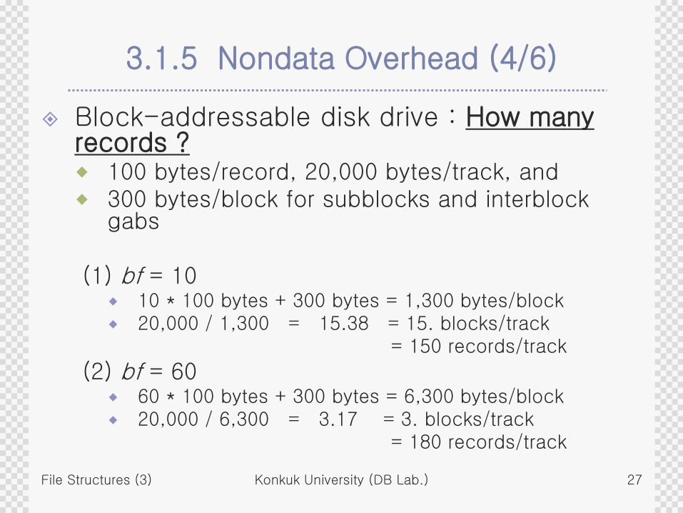
Block-addressable disk drive : How many records ? 100 bytes/record, 20,000 bytes/track, and 300 bytes/block for subblocks and interblock
gabs
(1) bf = 10 10 * 100 bytes + 300 bytes = 1,300 bytes/block 20,000 / 1,300 = 15.38 = 15. blocks/track = 150 records/track
(2) bf = 60 60 * 100 bytes + 300 bytes = 6,300 bytes/block 20,000 / 6,300 = 3.17 = 3. blocks/track = 180 records/track

File Structures (3) Konkuk University (DB Lab.) 28
3.1.5 Nondata Overhead (5/6)
The larger blocking factor, the more efficient use of storage
fewer blocks are required to hold a file
less space consumed by the overhead
the greater the block size, the greater potential amount of internal track fragmentation

File Structures (3) Konkuk University (DB Lab.) 29
3.1.5 Nondata Overhead (6/6)
Block
Flexibility rather than sector
save time for determine data organization
Blocking schemas require the programmer and/or operation system to do extra work of determining the data organization

File Structures (3) Konkuk University (DB Lab.) 30
3.1.6 The Cost of a Disk Access (1/3)
Disk access time
1. seek time to move the access arm to the correct cylinder
more costly in a multiuser environment
average seek traverses 1/3 of the total # of cylinders
2. rotational delay to rotate so the required sector is under the real/write head
average rotational delay is 1/2 of a revolution
(ex) Hard disk : 5000 rpm (12 msec/revolution)
Floppy disk : 360 rpm (166.6 msec/revolution)
3. transfer time # of bytes transferred / # of bytes on a track * rotation time
(ex) 63 sectors per track
=> Transfer time/sector = 1 / 63 * rotation time

File Structures (3) Konkuk University (DB Lab.) 31
3.1.6 The Cost of a Disk Access (2/3)
Some timing computations 9 - Gbyte fixed disk described in Table 3.1
Read 8704000 byte file that divided into 34000 256-byte records. Since the 4096 byte cluster holds sixteen records 8,704,000 bytes/file = 34,000 256-byte records/file (512 bytes/sector) = 2,125 clusters/file (8 sectors/cluster = 16 records/cluster = 4096 bytes/cluster))
File will be stored as a sequence of 2125 4096-byte clusters occupying on hundred tracks = 100 tracks/file <= 87.04 kbytes/tracks 512 * 170 = 87040

File Structures (3) Konkuk University (DB Lab.) 32
3.1.6 The Cost of a Disk Access (3/3)
(1) Sequential access average seek 8 msec
rotational delay 3 msec
read one track 6 msec
------------------------------------------
total 17 msec/track
total time = 100 * 17 msec = 1,700 msec = 1.7 sec/file
(2) Random access
average seek 8 msec
rotational delay 3 msec
read one cluster 0.28 msec (<= 1 / 21.25 * 6 msec)
------------------------------------------
total 11.28 msec/cluster
total time = 34,000 * 11.28 msec = 383,520 msec = 383.52 sec/file
File Structures (3) Konkuk University (DB Lab.) 33
3.1.8 Disk as Bottleneck(1/4)
Disk bound process The network and the computer’s CPU have
to wait inordinate lengths of time for the disk to transmit data
disk : 5 megabytes/sec
network : 100 megabytes/sec
CPU : more fast

File Structures (3) Konkuk University (DB Lab.) 34
3.1.8 Disk as Bottleneck(2/4)
Solutions for disk bound process
1. Multiprogramming
CPU works on other jobs while waiting for the data to arrive
2. Disk striping
splitting file on several different drivers
3. Buffering
avoid accessing the disk

File Structures (3) Konkuk University (DB Lab.) 35
3.1.8 Disk as Bottleneck(3/4)
2. Disk striping (RAID system) involve splitting the parts of a file on several different
drivers, then letting the separate drives deliver parts of the file to the network simultaneously (=> parallelism)
(ex) 10-megabyte file spread across 20 drives (5megabyte/sec) that hold 50 K per track
1 drive 2 drive 3 drive …. 20 drive
1st 50K 2nd 50K 3rd 50K 20th 50K
21th 50K 40th 50K
: :
: :
181th 50K 200th 50K
20 drives can deliver to the network 5 megabytes per second (combined rate = 100 megabytes/sec)

File Structures (3) Konkuk University (DB Lab.) 36
3.1.8 Disk as Bottleneck(4/4)
3. Buffering avoid accessing the disk
Programmers are using memory to hold data
(1) RAM disk
a large part of memory is configured to simulate the behavior of a mechanical disk in every respect except speed and volatility
without a seek or rotational delay, but volatile
(2) Disk cache
a large block of memory is configured to contain pages of data from a disk (256-Kbytes cache)
for high degree of locality
File Structures (3) Konkuk University (DB Lab.) 37
3.2 Magnetic Tape
Magnetic tape
no direct access, but very rapid sequential access
compact, stand up well, easy to store and transport
less expensive than magnetic disk
=> primarily used as archival storage or backup device

File Structures (3) Konkuk University (DB Lab.) 38
3.2.1 Types of Tape Systems
A variety of tape formats with various prices
=> See Table 3.3
Tape systems
1. Nine-track tapes 1/2-inch magnetic tape on 10.5-inch reels with
3600 feet of tape for reel-to-reel tape drives
use nine linear tracks
2. Tape cartridge the tape and its reels are contained in a box
4 mm, 8 mm, VHS, 1/2 inch, 1/4 inch
File Structures (3) Konkuk University (DB Lab.) 39
3.2.2 An Example of a High-Performance Tape System
StorageTek Redwood SD3 configured in a silo that contains storage racks, a tape
robot, and multiple tape drives
4-by-4 inch cartridges with 1/2 inch tapes are formatted with helical tracks
reliable storage time >= 20 years
average durability = 1 million head passes
tape capacities = 50 Gbytes, transfer rate = 11 Mbytes/sec
mount time <= 2 minutes without operator intervention
read or write time of a full tape = 75 minutes
with average seek time = 53 sec, max. rewind time = 89 sec,
load time = 17 sec
=> overhead to rewind, unload, and load = 3 %
File Structures (3) Konkuk University (DB Lab.) 40
3.2.3 Organization of Data on Nine-Track Tapes(1/2)
Magnetic tape no need for addresses
(logical position = physical position relative to the start of the file)
surface of a tape = a set of parallel tracks
9 tracks (Fig. 3.11) : 1 byte + parity bit (≡ frame)
Parity bit to check the validity of the data
odd parity* or even parity

File Structures (3) Konkuk University (DB Lab.) 41
3.2.3 Organization of Data on Nine-Track Tapes(2/2)
Data blocks groups of frames (bytes) whose size can vary
from a few bytes to many kilobytes
separated by interblock gabs to permit stopping & starting
Three quantities of tape drives 1. tape density : 800, 1600, 6250, 30,000 bpi (bit
per inch)
2. tape speed : 30 ~ 200 ips
3. interblock gab(IBG) size : 0.3 ~ 0.75 inch

File Structures (3) Konkuk University (DB Lab.) 42
3.2.4 Estimating Tape Length Requirements(1/4)
Ex) mailing-list file with 1 million 100-byte records on 6250 bpi, 0.3 inch/IBG tape
=> How much tape is needed ?
b = the physical length of a data block
g = the length of an interblock gap
n = the number of data blocks
s = the space requirement for the file
=> s = n * ( b + g )
File Structures (3) Konkuk University (DB Lab.) 43
3.2.4 Estimating Tape Length Requirements(2/4)
1. Blocking factor = 1 block size (bpb) 100 b = -------------- = ------ = 0.016 inch tape density (bpi) 6,250
n = 1,000,000 blocks
s = 1,000,000 * ( 0.016 + 0.3 ) inch
= 1,000,000 * 0.316 inch
= 316,000 inch
= 26,333 feet (316000/12)

File Structures (3) Konkuk University (DB Lab.) 44
3.2.4 Estimating Tape Length Requirements(3/4)
2. Blocking factor = 50 5,000 b = ------- = 0.8 inch 6,250 1,000,000 n = ---------- = 20,000 block 50
s = 20,000 * ( 0.8 + 0.3 ) inch
= 20,000 * 1.1 inch
= 22,000 inch
= 1,834 feet (22000/12) (1 * 2,400 - foot tape)

File Structures (3) Konkuk University (DB Lab.) 45
3.2.4 Estimating Tape Length Requirements(4/4)
Effective recording density (vs. 6250 bpi) number of bytes per block ---------------------------------- number of inches required to store a block
(1) bf = 1 100 bytes/block ----------------- = 316.4 bpi 0.316 inches/block
(2) bf = 50 5,000 bytes/block ----------------- = 4545.4 bpi 1.1 inches/block

File Structures (3) Konkuk University (DB Lab.) 46
Two factors for the data transmission rate
(1) nominal recording density
(2) speed with which the tape passes the read/write head
Nominal data transmission rate
tape density (bpi) * tape speed (ips)
= 6,250 (bpi) * 200 (ips)
= 1,250,000 bytes/sec
= 1,250 kilobytes/sec
3.2.5 Estimating Data Transmission Times(1/3)

File Structures (3) Konkuk University (DB Lab.) 47
Effective data transmission rate effective recording density (bpi) * tape speed (ips)
bf = 1 data transmission rate = 316.4 (bpi) * 200 (ips)
= 63,280 bytes/sec = 63.3 kilobytes/sec (약 1/20 * nominal rate)
bf = 50 data transmission rate = 4545.4 (bpi) * 200 (ips) = 909,080 bytes/sec = 909.1 kilobytes/sec
A larger blocking factor improves on effective transmission rate
3.2.5 Estimating Data Transmission Times(2/3)

File Structures (3) Konkuk University (DB Lab.) 48
Factors for space utilization and data transmission rate block size, gap size, tape speed,
recording density
3.2.5 Estimating Data Transmission Times(3/3)
File Structures (3) Konkuk University (DB Lab.) 49
3.3 Disk Versus Tape
Disk excellent for random access and storage of file
for which immediate access was desired
for several processes
=> between accesses : tend to require an expensive seek
Tape ideal for processing data sequentially and for
long-term storage of files
for one process

File Structures (3) Konkuk University (DB Lab.) 50
3.4 Introduction to CD-ROM
CD-ROM: Compact Disc Read-Only Memory
Can hold over 600MB(200,000 pages)
Useful for publishing or distributing medium

File Structures (3) Konkuk University (DB Lab.) 51
3.4.1 History of CD-ROM: Videodisc
Videodisc technology developed in late 1960's and early 1970's
The goal was to store movie
A number of methods for storing video signals
1. Use a needle to respond mechanically to grooves in a disc
2. Use optical storage
Many companies were fighting which approach should become a standard
VideodiskLaserVisionCD audioCD-ROM
File Structures (3) Konkuk University (DB Lab.) 52
3.4.1 History of CD-ROM: LaserVision
LaserVision Emerged as the winner of standard battles about
standard
Support CLV(Constant Linear Velocity) and CAV(Constant Angular Velocity) format
Fast seek performance by using CAV format
Data are stored in analog form
Why did they fail?
many incompatible encoding scheme and error correction techniques were used by many firms
No standard format

File Structures (3) Konkuk University (DB Lab.) 53
3.4.1 History of CD-ROM: CD-ROM
CD-ROM Philips and Sony developed CD-ROM in 1984 in order to
store music on a disc
Use a digital data format
In late 1985, videodisc/digital data industry moved into CD-ROM industry
In early summer of 1986, an official standard for organizing files was worked out
File Structures (3) Konkuk University (DB Lab.) 54
3.4.1 History of CD-ROM: DVD
DVD Digital Video Disc
The density of both tracks and bits has been increased to yield a sevenfold increase in storage capacity
DVD is available in a two-sided medium that yields 10 gigabytes per disc

File Structures (3) Konkuk University (DB Lab.) 55
3.5 Physical Organization of Master Disk
Master Disc
Formed by using the digital data, 0 or 1
Made of glass, has a Coating that is changed by the laser beam
Two part of CD-ROM
Pit
The areas that is hit by the laser beam
Scatter the light
Land
Smooth, unchanged areas between pits
Reflect the light
laser beam
pit
land
light

File Structures (3) Konkuk University (DB Lab.) 56
3.5.1 Encoding Scheme of CD-ROM
Encoding scheme
1 : transition from pit to land and back again
0s : the amount of time between transitions
Constraint there must be at least two 0’s between any pair of
1’s (no two adjacent 1s)
We cannot represent all bit patterns, thus, we need translation scheme
We need at least 14 bits to represent 8 bits under this constraint

File Structures (3) Konkuk University (DB Lab.) 57
3.5.3 CLV instead of CAV
지속적 선형속도(CLV : Constant Linear Velocity) 형식 안에서 바깥쪽으로 탐색해 갈 때 광 픽업을 지나가는 나선형의
선형속도는 일정하므로 디스크의 회전 비율을 변화 시킴
CLV 형식은 CD-ROM 드라이브의 좋지 못한 탐색 성능을 유발
특정 위치로 가기 위한 일반적인 방법이 없다
큰 용량을 얻을 수 있다
지속적 각속도(CAV : Constant Angular Velocity) 같은 동심원을 갖는 트랙으로 파이 모양의 섹터를 갖고 있어 안
쪽에 있는 트랙보다 바깥쪽의 트랙에 더 적은 밀집도로 자료를 저장
바깥쪽 트랙에 대해서 저장장치의 낭비가 있지만 어느 위치에 대해서도 같은 속도로 디스크가 회전

File Structures (3) Konkuk University (DB Lab.) 58
3.5.3 CLV instead of CAV
Format of CD-ROM CLV(Constant Linear Velocity)
Same amount of space for each sector
Rotational speed is slower in reading outer edge than in inner edge
Characteristics
Poor seek performance
No straightforward way to jump to a specified location
File Structures (3) Konkuk University (DB Lab.) 59
3.5.3 Addressing of CD-ROM
Addressing Magnetic disk: cylinder/track/sector approach CD-ROM: a sector-addressing scheme
Track density varies thus, each second of playing time on a CD is divided into 75 sectors 75 sectors/sec, 2 Kbytes/sector At least one-hour of playing time
60 min * 60 sec/min * 75 sectors/sec = 270,000 sectors Maximum capacity can be calculated: 600 Mbytes (70분 기준)
We address a given sector by referring minutes, second, and sector of play 16:22:34 means 34th sector in the 22nd second in the 16th
minutes of play

File Structures (3) Konkuk University (DB Lab.) 60
3.6 CD-ROM Strengths and Weakness
Strong aspects of CD-ROM
Data transfer rate: 75 sectors/sec
Storage capacity : over 600 Mbytes
Weak aspects of CD-ROM
Poor seek performance (weak random access) Magnetic disk: 30 msec, CD-ROM : 500 msec
Comparison of access time of a large file from several media RAM: 20 sec, Disk: 58 days, CD-ROM: 2.5 years

File Structures (3) Konkuk University (DB Lab.) 61
3.7 Storage as a Hierarchy
Hierarchy of storage devices : Fig. 3.17 different access time, capacity, and cost
(1) Primary storage registers, memory, RAM disk, disk cache :
semiconductors
(2) Secondary storage direct-access : magnetic disks
serial : tape, mass storage
(3) Offline storage archival and backup : removable magnetic
disks, optical discs, tapes

File Structures (3) Konkuk University (DB Lab.) 62
3.8 A Journey of a Byte
write(textfile, ch, 1) Write 문장
운영체제에게 문자 한 개를 디스크로 보낼 것을 지시하며 운영체제에게 문자의 위치를 알려 준다.
운영체제는 쓰기 작업을 호출 한 후 호출 프로그램에게 제어(control)을 되돌려 준다
P
사용자 프로그램:
write(textfile,ch,1)
......
......
운영체제의 화일 입,출력 시스템
사용자 프로그램의 데이타 영역에 있는
변수 ch로부터 1 바이트를 가져온다.
textfile에서 현 위치로 그 1 바이트를 쓴다
사용자 데이타 영역:
ch:

File Structures (3) Konkuk University (DB Lab.) 63
User Program Operating system File manager I/O processor Disk controller
3.8 A Journey of a Byte
I/O buffer
disk

File Structures (3) Konkuk University (DB Lab.) 64
3.8.1 The File manager (1/3)
1 The program asks the OS to write the contents of the variable ch to
the next available position in textfile.
2 The OS passes the job on to the file manager
3 The file manager looks up textfile in a table containing information
about it, such as whether the file is open and available for use, what
types of access are allowed, if any, and what physical file the logical
name textfile corresponds to.
4 The file manager searches a FAT for the physical location of the
sector that is to contain the byte.
5 The file manager makes sure that the last sector in the file has been
stored in a system I/O buffer in RAM, then deposits the ‘P’ into its
proper position in the buffer.
Logical layer

File Structures (3) Konkuk University (DB Lab.) 65
3.8.1 The File manager (2/3)
6 The file manager gives instructions to the I/O processor about where
the byte is stored in RAM and where it needs to be sent on the disk
7 The I/O processor finds a time when the drive is available to receive
the data and puts the data in proper format for the disk. It may also
buffer the data to send it out in chunks of the proper size for the disk.
8 The I/O processor sends the data to the disk controller.
9 The controller instructs the drive to move the r/w head to the proper
track, waits for the desired sector to come under the r/w head, then
sends the byte to the drive to be deposited, bit-by-bit, on the surface
of the disk.
Physical layer
File Structures (3) Konkuk University (DB Lab.) 66
3.8.1 The File manager (3/3)
File manager v.s. O.S. programs that deal with file-related matters and I/O devices
several layers of procedures : logical ~ physical
(i) check the logical characteristics of the file
whether the file has been opened
what type of file the byte is being sent to (binary, text file)
who the file's owner is
whether write access is allowed for the user
(ii) determine where in the file textfile the P is to be deposited
=> physical location of the last sector ( <= FAT )
(iii) locate the drive, cylinder, track, and sector where the byte is to be stored
File Structures (3) Konkuk University (DB Lab.) 67
3.8.2 The I/O Buffer (1/2)
(iv) determine whether the sector that is to contain the P is already in RAM or needs to be loaded into RAM
(v) if not, find an available system I/O buffer space for it and read it from disk
(vi) deposit the P into its proper position in the buffer
(vii) file manager usually wait to see if the sector can accumulate more bytes going to the same sector before actually transmitting anything
=> sometime can’t wait.
ex) if text file were closed, flush all output buffers

File Structures (3) Konkuk University (DB Lab.) 68
3.8.2 The I/O Buffer (2/2)
P
P
사용자 프로그램:
write(textfile,ch,1)
......
......
화일 입,출력 시스템
1.필요하다면 textfile로부터 마지막
섹터를 시스템 출력버퍼에 적재하라
2.P를 시스템 I/O 버퍼로 이동시켜라
I/O 시스템의
I/O 버퍼
사용자 데이타 영역:
ch:

File Structures (3) Konkuk University (DB Lab.) 69
3.8.3 The Byte Leaves Memory : The I/O Processor and Disk Controller(1/3)
Data path
the byte traveled along data paths 1. internal data path (CPU) : 32 bits in fast speed
2. external data path (disk) : 16 bits in slow speed
bottlenecks caused by differences in speeds & widths
I/O Processor
takes its instructions from the O.S., but once it begins processing I/O, it runs independently

File Structures (3) Konkuk University (DB Lab.) 70
3.8.3 The Byte Leaves Memory : The I/O Processor and Disk Controller (2/3)
Information(program) : file manager => I/O Processor 1. data in the buffer that is to be transmitted to the disk 2. how much data there is 3. where it is to go on the disk
Disk controller : responsible for the job of actually controlling the operation
of the disk instruct the disk drive to set the read/write head to the
desired sector, then sends the byte to the drive to be deposited

File Structures (3) Konkuk University (DB Lab.) 71
3.8.3 The Byte Leaves Memory : The I/O Processor and Disk Controller(3/3)
P
P
사용자 프로그램:
......
......
......
화일
관리기
....
I/O 프로세서 호출
....
....
I/O
프로세서
프로그램
....
....
.... ‘P’
‘P’
사용자 데이타 영역:
ch:
디스크
제어기
I/O 프로세서
시스템 버퍼

File Structures (3) Konkuk University (DB Lab.) 72
3.9 Buffer Management
Buffer the part of main memory available for storage of copies of
disk blocks
not controlled by programmers, but by the operating system
Buffering work with large chunks of data in memory so the number of
accesses to secondary storage can be reduced
the use of system I/O buffers within programs can substantially affect performance

File Structures (3) Konkuk University (DB Lab.) 73
3.9.1 Buffer Bottlenecks (1/2)
If a program for both input and output on one character at a time and only one I/O buffer (i) program asks for its first character
I/O buffer is loaded with the sector containing the character
the character is transmitted to the program
(ii) program decides to output a character I/O buffer is filled with sector that will contain the character
(i.e., destroy its original contents)
(iii) program asks for the next character buffer contents have to be written to disk to make room for
the (original) sector containing the second input character
I/O systems almost always use at least two buffers one for input and one for output

File Structures (3) Konkuk University (DB Lab.) 74
3.9.1 Buffer Bottlenecks (2/2)
Program transmits data in only one direction
use of a single system I/O buffer Waiting for the I/O system to fill its buffer
use multiple buffers CPU : process the current buffer
I/O system : fill the next buffer
overlapping

File Structures (3) Konkuk University (DB Lab.) 75
3.9.2 Buffering Strategies (1/7)
Double buffering:
the method of swapping the roles of two buffers after each output (or input) operation
O.S. : operating on one buffer
I/O system : loading or emptying the other buffer
overlapping

File Structures (3) Konkuk University (DB Lab.) 76
3.9.2 Buffering Strategies (2/7)
Double buffering
Program data area
Program data area
To disk
To disk I/O buffer 1
I/O buffer 1
I/O buffer 2
I/O buffer 2

File Structures (3) Konkuk University (DB Lab.) 77
3.9.2 Buffering Strategies (3/7)
Buffer pooling
when a system buffer is needed, it is taken from a pool of available buffers and used
buffer selection for replacement : least recently used (LRU)

File Structures (3) Konkuk University (DB Lab.) 78
3.9.2 Buffering Strategies (4/7)
Buffer handling (by file manager)
1. move mode data : system buffer (RAM) <=> program buffer (RAM)
(= program's data area)
take the amount of time
2. locate mode (1) data : secondary storage <=> program's data area
- no extra move
(2) use system buffers to handle all I/O, but provide the program with the locations of the system buffers
- program can operate directly on data in the I/O buffer

File Structures (3) Konkuk University (DB Lab.) 79
3.9.2 Buffering Strategies (5/7)
Move mode & Locate mode
system
buffer
program’s
data area
system
buffer
disk
disk user’s
program location
(pointer)
Move
mode
Locate
mode

File Structures (3) Konkuk University (DB Lab.) 80
3.10 I/O in UNIX 3.10.1 The Kernel (1/9)
Kernel I/O Structure 1. topmost layer
deal with data in logical, structural terms (e.g., name, a body of text, an image, an array of numbers, or some other logical entity)
application view on a file
processes ... shell routines (cat, tail), user programs, library routines (scanf(), fread())
2. bottom layers carry out the task of turning the logical object into a
collection of bits on a physical device
system view on a file
UNIX Kernel ... views all I/O as operating on a sequence of bytes

File Structures (3) Konkuk University (DB Lab.) 81
3.10.1 The Kernel (2/9)
I/O system
PROCESSES
KERNEL
User programs Libraries Shell commands
System call
interface
Block I/O
system
(normal
files)
Character
I/O system
(terminals,
printers, etc.)
Network
I/O system
(sockets)
block device drivers
disk disk...
character device drivers
consoles printers...
network interface drivers
...networks...
HARDWARE

File Structures (3) Konkuk University (DB Lab.) 82
3.10.1 The Kernel (3/9)
Journey of a byte
write (fd, &ch, 1); (vs. fprintf(): library call)
(i) the system call instructs the kernel to write a character to a file
(ii) the kernel I/O system begins by connecting the file descriptor (fd) to some file or device (scan a series of 4 tables)
file descriptor table
open file table
file allocation table
table of index nodes (inode table)

File Structures (3) Konkuk University (DB Lab.) 83
3.10.1 The Kernel (4/9)
File descriptor table owned by the process (your program)
associates each of the file descriptors used by a process with an entry in the open file table
every process has its own descriptor table
includes entries for all opened files, including stdin, stdout, stderr

File Structures (3) Konkuk University (DB Lab.) 84
3.10.1 The Kernel (5/9)
Open file table owned by the kernel
contains entries (called "file structures") for every open file
R/W mode, the number of processes currently using it, offset of next access, pointers to generic functions (i.e., read and write routines), inode table entry, etc.
transitory (during opened)

File Structures (3) Konkuk University (DB Lab.) 85
3.10.1 The Kernel (6/9)
Two methods of file open
1. several different processes can refer to the same open file table entry
two processes : dependent
2. the same file can be opened by two separate open() statements (i.e., two separate entries)
two processes : independent

File Structures (3) Konkuk University (DB Lab.) 86
3.10.1 The Kernel (7/9)
File allocation table (FAT) owned by the kernel
a list(index) of the disk blocks that make up the file
dynamic tree - like structure, not a simple linear array
inode (index node) table owned by the kernel
when a file is opened, a copy of its inode is usually loaded into the inode table in memory for rapid access

File Structures (3) Konkuk University (DB Lab.) 87
3.10.1 The Kernel (8/9)
Index node (inode) permanent (during the existence of files), so kept on disk
with the file
information about file position, file size, owner's id, permissions, block count, etc.
=> once the kernel's I/O system has the inode information,
it invokes an I/O processor program (≡ device driver)
Device driver appropriate for the type of data, the type of operation, and
the type of device that is to be written
see that your data is moved from its buffer to its proper place on disk

File Structures (3) Konkuk University (DB Lab.) 88
3.10.1 The Kernel (9/9)
An inode
device
permissions
file size
block count
file
allocation
table
owner’s userid

File Structures (3) Konkuk University (DB Lab.) 89
3.10.2 Linking File Names to Files (1/3)
Directory
a small file that contains, for each file, a file name together with a pointer (called "hard link") to the file's inode on disk
file name : 14 bytes, inode number : 2 byes

File Structures (3) Konkuk University (DB Lab.) 90
3.10.2 Linking File Names to Files (2/3)
Hard link an entry in a directory that connects a file name to the
inode of the corresponding file
several file names can point to the same inode
when a file name is deleted, file itself is not deleted, but its hard-link count is decremented by one
Soft link (or symbolic link) an entry in a directory that gives the pathname of a file
links a file name to another file name rather than to an actual file (i.e., an indirect pointer to a file)
can refer to a directory or even to a file in a different file system

File Structures (3) Konkuk University (DB Lab.) 91
3.10.2 Linking File Names to Files (3/3)
Shell commands
ln file-name1 file-name2 (cf., link()) two file names have the same inode number
rm file-name, …
it removes directory entries & links
cp file-name1 file-name2 two file names have different inode numbers
mv file-name1 file-name2 file name is changed, but with the same inode number

File Structures (3) Konkuk University (DB Lab.) 92
3.10.3 Normal Files, Special Files, and Sockets
Three types of files
1. Normal files files that this text is about
2. Special files represent a stream of characters and control signals
that drive some devices (e.g., line printer or graphic device)
3. Sockets abstractions that serve as endpoints for interprocess
communication
=> many of the same routines can be used to access any of them (e.g., open() and write() system calls)

File Structures (3) Konkuk University (DB Lab.) 93
3.10.4 Block I/O
Three I/O systems
1. block I/O system for block-oriented device like a disk or a tape
access blocks randomly
sequence of bytes <=> block
block size = 512 bytes(common sector size) -> 1024 bytes
2. character I/O system for character-oriented device like a keyboard or a
printer
read and write streams of data, not blocks
3. network I/O system

File Structures (3) Konkuk University (DB Lab.) 94
3.10.6 The Kernel and File systems
Separation (file system ⊂ kernel) 1. all parts of a file system
reside on disk
some parts are brought into memory by the kernel as needed
2. kernel reside in memory
Advantages of separation we can tune a file system to a particular device or usage
pattern independently of how the kernel views files
we can have separate file systems that are organized differently, perhaps on different devices, but are accessible by the same kernel (e.g., file system on CD-ROM)