chapter 3 lubrication - manitex
TRANSCRIPT

Chapter 3Lubrication
Avoid injury! Bring all crane functions to completestop and turn engine OFF before lubricating crane.If necessary, spot grease fittings at access points,
then stop engine.
Attach CAUTION sign to start controls to warn personnel that craneis being serviced and engine must not be started.
Do not operate crane until all guards and covers have been securelyreplaced and all maintenance equipment has been removed.
3-1C-Series Operator Manual

3-2
Chapter 3: Lubrication
GeneralTo insure proper operation of this crane, all points requiring lubrication must be serviced with the correct lubricant at the proper interval. All normal wear points requiring lubrication are covered in this section, except for the truck. Lubri-cate and maintain truck according to instructions in manufacturer�s manual.
IntervalsThe intervals given in this section are based on normal operating conditions.
Any increase or decrease in these intervals shall be preceded by a complete analysis of how the crane is performing.
Bearings or bushings that are too warm, excessive play in moving parts, excessive or abnormal wear in gears, and rust accumulation are indications of a lack of lubrication. If these conditions are found, the lube interval for the faulty part should be shortened.
Important Before lengthening intervals, check that all parts are receiving an adequate supply of clean lubricant, other-wise, parts will be damaged from a lack of lubrication.
A laboratory analysis of oil from hydraulic tank and each gear box shall be major factor used in determining whether oil-change intervals should be lengthened or shortened.
Over-LubricationOver-lubrication is not only wasteful but also harmful.
� Oil or grease that drips onto walkways can cause personnel to slip and be hurt.� Too high of an oil level can cause churning and foaming of the oil and result in excessive heat and overflow from
the hydraulic tank or gear boxes.� An extra shot of grease, if too stiff or under too much pressure, can pop out a bearing seal.
Service Tips� Check oil levels before start-up so the oil has had a chance to run down from the hydraulic tank and gear box
walls and all moving parts.� Avoid introducing dirt into the hydraulic tank or gear boxes. Carefully clean the area around dipsticks, level
plugs, fill plugs and breathers before removing them.� Securely replace level plugs, fill plugs, drain plugs and breathers. Clean any spillage.� Keep oil and grease dispensers and containers tightly closed and stored in a dirt and moisture free location.� Clean grease fittings before and after applying grease.� Apply grease until the bearing is full so grit cannot enter. Wipe away excess grease.
Oil Can PointsOil all pins not equipped with grease fittings with engine oil every month even if the crane is not being operated.
Wire RopeThe wire rope must be lubricated on a regular basis to maintain its strength and lengthen its useful life. Refer to the Rigging Chapter for lubrication instructions.
C-Series Operator Manual
Chapter 3: Lubrication
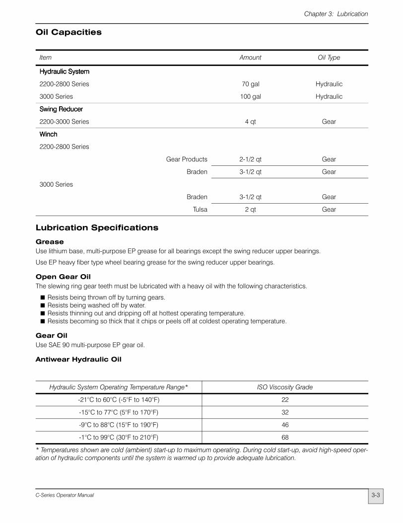
Oil Capacities
Lubrication Specifications
GreaseUse lithium base, multi-purpose EP grease for all bearings except the swing reducer upper bearings.
Use EP heavy fiber type wheel bearing grease for the swing reducer upper bearings.
Open Gear Oil The slewing ring gear teeth must be lubricated with a heavy oil with the following characteristics.
� Resists being thrown off by turning gears.� Resists being washed off by water.� Resists thinning out and dripping off at hottest operating temperature.� Resists becoming so thick that it chips or peels off at coldest operating temperature.
Gear Oil Use SAE 90 multi-purpose EP gear oil.
Antiwear Hydraulic Oil
Item Amount Oil Type
Hydraulic SystemHydraulic SystemHydraulic SystemHydraulic System
2200-2800 Series 70 gal Hydraulic
3000 Series 100 gal Hydraulic
Swing ReducerSwing ReducerSwing ReducerSwing Reducer
2200-3000 Series 4 qt Gear
WinchWinchWinchWinch
2200-2800 Series
Gear Products 2-1/2 qt Gear
Braden 3-1/2 qt Gear
3000 Series
Braden 3-1/2 qt Gear
Tulsa 2 qt Gear
Hydraulic System Operating Temperature Range* ISO Viscosity Grade
-21°C to 60°C (-5°F to 140°F) 22
-15°C to 77°C (5°F to 170°F) 32
-9°C to 88°C (15°F to 190°F) 46
-1°C to 99°C (30°F to 210°F) 68
* Temperatures shown are cold (ambient) start-up to maximum operating. During cold start-up, avoid high-speed oper-ation of hydraulic components until the system is warmed up to provide adequate lubrication.
3-3C-Series Operator Manual

3-4
Chapter 3: Lubrication
Lubrication Points
Identification (Figure 3-1) Lubricant Service Interval Note1. Hydraulic Tank Fill Cap Hydraulic Oil Check Level Daily 12. Hydraulic Filter � Check Pressure Daily 23. Retract Sheaves Grease Grease Gun Weekly 34. Extend and Retract Sheaves Grease Grease Gun Weekly 45. Boom Point Sheaves (1 fitting each sheave) Grease Grease Gun Weekly �6. Jib Point Sheave Grease Grease gun Weekly �7. Auxiliary Block Grease Grease gun Weekly �8. Load Block Sheave (1 or 2 fittings) Grease Grease Gun Weekly �9. Load Block Trunnion or Overhaul Ball Swivel Grease Grease Gun Weekly �10. Slewing Ring Gear Teeth Open Gear Oil Brush or Spray Weekly 511. Swing Reducer Gear Oil Check Level Weekly 612. Winch Gear Oil Check Level Weekly 613. Control Linkage Engine Oil Oil Can Monthly 713a. Boom and Hoist Cylinder Pivot Pins Grease Grease Gun Weekly 1614. Slewing Ring Bearing Grease Grease Gun Monthly 815a. Outrigger Pins (2 fittings each outrigger) Grease Grease Gun Monthly �15b. Ball Cavity (outrigger and stabilizer float pads) Grease Brush or Swab Monthly �16. Boom Slider Pads Grease Brush or Swab Weekly 917. Outrigger and Stabilizer Slider Pads Grease Brush or Swab Monthly 1018. Winch Vent Plug � Clean Monthly 1119. hydraulic Tank Breather � Replace Every 3 Months 1220. Hydraulic Tank Hydraulic Oil Change Semiannually 1321. Suction Strainer � Clean At oil change �22. Swing Reducer Upper Bearings EP Heavy Grease Grease Gun Annually 1423. Swing Reducer Gear Oil Change Annually �
24. Winch Gear Oil ChangeEvery 1000 Hoursor Semiannually
15
1212 20 191715a15b
15a15b
13
17
9
4
5
7
8
15a
13a
3
18
12
24Cover Removed
16
10 22 11 23
14 16 6
Jib Point
13a
Figure 3-1 Lubrication Points
C-Series Operator Manual

Chapter 3: Lubrication
Lubrication Points Notes1. Fill hydraulic tank so oil level is between high and low marks on tank sight gauge. To check the oil level, the crane
must be in the normal roading position; i.e., the boom must be in the boom rest and all outriggers fully retracted.
2. Check the gauge after start-up each day and periodically throughout each work shift. Replace element if gauge reads 25 psi when engine is at high idle and oil is warm.
3. Retract sheave(s) on first section accessible through rear of boom. Fittings are located on each end of sheave pin or on exposed side of sheave.
4. Fittings are located on each end of sheave pins. Boom must be fully extended to expose all grease fittings through holes on each side of the boom sections.
Do not place hands or tools into any opening in boom sections while power is on orboom sections are moving.
5. Open gear oil must be brushed or sprayed on each gear tooth; do not rely on gear rotation to distribute oil. An access hole is provided in swing cover.
6. Fill to bottom of plug opening.
7. Remove cover to expose linkage. Replace cover after servicing.
8. The slewing ring has one or two grease fittings in inner ring accessible through slotted holes in turret when boom is aligned with flatbed. Apply five shots of grease to each fitting.
9. Fully extend boom and apply a light coat of grease to both sides and bottom of each boom section in areas of slider pad contact.
Fully retract boom. Remove cover from rear of boom base to expose top rear slider pads. Coat top rear slider pads with grease. Extend boom as necessary to expose each set of slider pads. Replace cover after greasing.
Do not place hands or tools into any opening in boom sections while power is on orboom sections are moving.
Note Chattering or jerking of the boom indicates more frequent lubrication of the boom and pads is required. For recomended boom break-in procedure see chapter 6 under �Boom Service�
10. Refer to Figure 3-2 thru 3-5 for lubrication of outrigger and stabilizer slider pads.
11. Clean vent plug by soaking in solvent. Spring loaded pin must move in and out freely. Do not paint over vent plug. Never replace vent plug with a solid plug.
12. Do not attempt to clean breather; if needed, replace at earlier intervals.
13. See Chapter 6 for oil change procedure.
14. Swing boom slowly in both directions while greasing to completely fill bearing. An access hole is provided in swing cover.
15. To drain winch oil, boom must be horizontal.
To drain winch oil, align plug in drum with drain hole in bottom of side plate. Screw a short piece of 1-inch pipe into large hole in drum. Insert a 3/8-inch drive extension through pipe and remove plug. Replace plug and remove pipe after oil has drained.
Do not place fingers, pipe, or drive extension into hole in side plate until winch drumhas stopped turning and engine is OFF.
16. Grease fittings on cylinders are located on the middle of cylinder pin tubes. Fitting on the boom pivot is located on the center of the tube and accessible from the rear of the boom.
3-5C-Series Operator Manual
3-6
Chapter 3: Lubrication
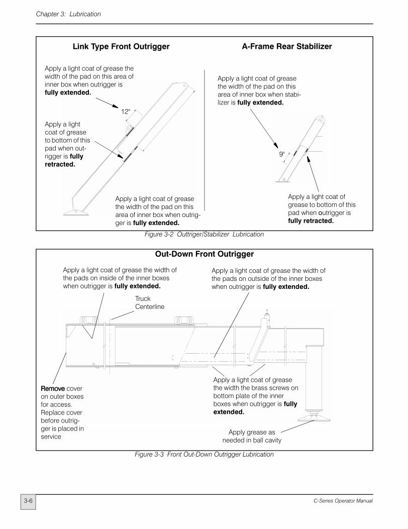
Link Type Front Outrigger
12"
9"
Apply a light coat of grease the width of the pad on this area of inner box when stabi-lizer is fully extended.
Apply a light coat of grease to bottom of this pad when outrigger is fully retracted.
A-Frame Rear Stabilizer
Apply a light coat of grease the width of the pad on this area of inner box when outrig-ger is fully extended.
Apply a light coat of grease the width of the pad on this area of inner box when outrigger is fully extended.
Apply a light coat of grease to bottom of this pad when out-rigger is fully retracted.
Apply a light coat of grease the width the brass screws on bottom plate of the inner boxes when outrigger is fully extended.
Out-Down Front Outrigger
Apply a light coat of grease the width of the pads on inside of the inner boxes when outrigger is fully extended.
Apply grease as needed in ball cavity
Truck Centerline
RemoveRemoveRemoveRemove cover on outer boxes for access. Replace cover before outrig-ger is placed in service
Apply a light coat of grease the width of the pads on outside of the inner boxes when outrigger is fully extended.
Figure 3-2 Outtriger/Stabilizer Lubrication
Figure 3-3 Front Out-Down Outrigger Lubrication
C-Series Operator Manual

Chapter 3: Lubrication
Truck Centerline
Apply a light coat of grease the width of the pads on inside of the inner boxes when outrigger is fully extended.
Apply grease as needed in
ball cavity
Apply a light coat of grease the width of the pad on bottom of the inner boxes when outrigger is fully extended.
Remove cover on outer boxes for access. Replace cover before outrigger is placed in service
Rear Out-Down Stabilizer (dual main box)
Apply a light coat of grease the width of the pads on outside of the inner boxes when outrigger is fully extended.
Apply a light coat of grease the width of the pads on outside of this inner box when outrigger is fully extended.
Apply a light coat of grease the width of the pad on bottom of the inner boxes when outrigger is fully extended.
Apply grease as needed in
ball cavity
Rear Out-Down Stabilizer (single main box)
Figure 3-4 Rear Stabilizer Lubrication
Figure 3-5 Rear Stabilizer Lubrication
3-7C-Series Operator Manual

3-8
Chapter 3: Lubrication
C-Series Operator Manual