chapter 3 dynamic response of 2 dof quarter car...
TRANSCRIPT

53
______________________________________________________________________
CHAPTER 3
DYNAMIC RESPONSE OF 2 DOF QUARTER CAR PASSIVE
SUSPENSION SYSTEM (QC-PSS) AND 2 DOF QUARTER CAR
ELECTROHYDRAULIC ACTIVE SUSPENSION SYSTEM
(QC-EH-ASS)
3.1 INTRODUCTION
In this chapter, the dynamic response analysis of a 2 DOF
Quarter Car Electro-Hydraulic Active Suspension System (EH-
ASS) has been carried out in the spirit and approach of Lin and
Kaddissi [50]. This Analysis is further used in the validation of
results of Simulation analysis in a state-of-the-art MATLAB
SIMULINK R 2010 environment which is reported in chapter 4.
The analysis of vehicle suspension system has been performed
using different suspension models. In recent research projects on
suspension system, a quarter car model is being preferred over
other many DOF models. It has immerged as the most employed
and useful vehicle suspension system analysis tool, because of its
simplicity and yet it is capable of capturing many critical
characteristics of the full car model. In this research work,
therefore, it is felt appropriate, to use a 2DOF Quarter Car Model
for theoretical analysis of the Road Vehicle Suspension System
which is later fabricated and analysed in the institute‘s
laboratory.

54
3.2 SCHEMATIC OF 2 DOF QUARTER CAR ELECTRO-HYDRAULIC ACTIVE
SUSPENSION SYSTEM (QC-EH-ASS)
Fig. 3.1 A Typical 2DOF Quarter Car Electro-Hydraulic Active Suspension System Model
Figure 3.1describes the scheme of a 2DOF Quarter Car Electro-
Hydraulic Active Suspension System Model which is taken up for
its dynamic response analysis. Here the sprung mass ms is one
fourth of the mass of car body and attached to unsprung mass
through a passive spring and damper alongwith an active element
in the form of a hydraulic actuator and electro-hydraulic servo
valve. The hydraulic actuator force is viewed as control input. The
vehicle tyre is modeled as a simple spring neglecting tyre damping.
We can add a damper with damping coefficient Cu in parallel to
spring with spring stiffness Kt, to model the damping in tires.
However, the value of Cu for tires, compared to Cs, is very small,
and hence, Cu is not considered in modeling of 2 DOF Quarter Car
Suspension System. In this case,
= Sprung Mass (mass of car body)
= Unsprung Mass (mass of chassis and wheel)
= Spring Stiffness
= Tire Stiffness

55
= Damping Coefficient
= Sprung Mass displacement
= Unsprung Mass displacement
r = Road Disturbance
ua = Actuator Force
Ps = Supply Pressure
Pr = Return Pressure
3.3 EQUATIONS OF MOTION
Here the scheme as shown in fig. 3.1 is considered for development of the
mathematical models for the following:
1. Case 1
2. Case 2
3.3.1 CASE 1 (WITHOUT ACTUATION: PASSIVE SUSPENSION)
Assuming that there is no active element (i.e. actuator in between
the sprung and unsprung mass), the system will depict the
conventional 2DOF Quarter Car Passive Suspension model.
Fig. 3.2: Conventional 2 DOF Quarter Car Passive Suspension System Model
The governing differential equations of motion for this system are [15],
( )+ ( - ) + ( - ) = 0
+ ( - ) + ( -r ) = 0 --------------- (1)

56
Taking state variables as
= , = = , = we obtain
=
= -
[ ( - ) + ( - )]
=
=
[ ( - ) + ( - ) - ( - r)] -------------- (2)
Frequency domain analysis is used as it is assumed that the passive suspension system
is linear,
Here, r (Road disturbance) is input and displacements ( ) and ( ) are the
responses.
Following the usual procedure of L.T. transfer functions theory, we get
transmissibilities H1 P(s) and H3 P(s) as
H1 P(s) = ( )
( ) =
( )
( )
H3 P(s) = ( )
( ) =
( )
( ) ------------- (3)
Here ( ) = Laplace transfer function of ( )
( ) = Laplace transfer function of ( )
( ) = Laplace transfer function of ( ) and
( ) = ( ) (
)
------ (4)
with,
=
=
=
=
and ω0 = √
(natural frequency of )
These functions are obtained by the simulation carried out with the
MATLAB SIMULINK 2010 environment using values taken from
Table 3.1.

57
TABLE 3.1: Suspension Parameters and Constants used for Transfer Functions in Case-I
Parameter Characteristics
Sprung mass ( Ms) 8 kg
Unsprung mass ( Mus) 1.5 kg
Suspension spring stiffness ( Ks) 13900 N/m
Suspension Damping coefficient ( Cs) 518 Ns/m
Tire spring stiffness ( Kt) 85000 N/m
Natural Frequency Of (ω0 ) 76 rad/sec
Constant A1=
33.45
Constant A2 =
101.4
Constant =
35.23
Constant =
540.81
Upon substituting above mentioned suspension characteristics of
road vehicle of a small car with mass ratio of 5.00, the value of the
transmissibility is determined as 0.45 which is nearly equal to the
value of 0.477 obtained from simulation of the X1(t) and X3(t) in
result fig. 4.5 and fig. 4.6.

58
3.3.2 CASE 2 (WITH ACTUATION: ACTIVE SUSPENSION)
The schematic of the case is shown in fig. 3.3
Figure 3.3: 2 DOF Quarter Car Electro-Hydraulic Active Suspension System Model
Equations of motion:
( )+ ( - ) + ( - )- = 0
+ ( - ) + ( - ) + ( -r) + = 0 -------- (5)
Using state variables,
= , = = , =
Reformulating (5) into state space representation as,
=
= -
[ ( - ) + ( - )- ]
=
=
[ ( - ) + ( - ) - ( - r)- ] ----------- (6)
Here, is the control force used as input signal.
Here, before going into the details of the further mathematical
modeling, it will be appropriate to discuss the potentials of
available control strategies and relevance of selection of a proper
control methodology for the active suspension system model
undertaken for the analysis. Thus, following section deals with
the characteristics and brief comparison of merits and
limitations of following control strategies.

59
3.4 COMPARISON OF POTENTIAL CONTROL STRATEGIES
WITH RELATIVE MERITS AND LIMITATIONS
In the past years, various control strategies have been proposed
by numerous researchers to improve the trade-off between ride
comfort and road handling. These control strategies may be
grouped into techniques based on linear, nonlinear and
intelligent control approaches. In the following, some of these
control approaches that have been reported in the literature will
be briefly presented.
3.4.1 STUDY OF VARIOUS CONTROL STRATEGIES
The most popular linear control strategy that has been used by
researchers in the design of the active suspension system is
based on the optimal control concept (Hrovat, 1997). Amongst
the optimal control concepts used are the Linear Quadratic
Regulator (LQR) approach, the Linear Quadratic Gaussian (LQG)
approach and the Loop Transfer Recovery (LTR) approach.
These methods are based on the minimization of a linear
quadratic cost function where the performance measure is a
function of the states and inputs to the system.
Application of the LQR method to the active suspension system
has been proposed by Hrovat (1988), Tseng and Hrovat (1990)
and Esmailzadeh and Taghirad (1996). Hrovat (1988) has
studied the effects of the unsprung mass on the active
suspension system. The carpet plots were introduced to give a
clear global view of the effect of various parameters on the
system performances. The carpet plots are the plots of the root
mean square (r.m.s) values of the sprung mass acceleration and
unsprung mass acceleration versus the suspension travel. The
r.m.s. values of all parameters are obtained from a series of
simulations on different weights of the performance index.
Since it is desirable to measure all the system states in the
actual implementations, observers are usually used. Ulsoy et al.

60
(1994) used Kalman filter to reconstruct the states and to
address the problem of the sensors noise and road
disturbances. In the study, the robustness margin of the LQG
controllers with respect to the parameter uncertainties and
actuator dynamics were investigated. The results showed that
the LQG controllers, using some measurements, such as the
suspension stroke, should be avoided since the controllers did
not produce the satisfactory robustness. LQG with loop transfer
recovery (LQG/LTR) was studied by Ray (1993) as a solution to
increase the robustness of the LQG controllers. However, when
applying LTR, uncertain system parameters must be identified,
and the magnitude of uncertainty expected should be known or
estimated; otherwise, LQR/LTR system may exhibit robustness
qualities that are not better than the original LQG system.
Most researchers that utilized the linear control approach did
not consider the dynamics of the actuators in their study. Thus,
the control strategies that have been developed did not
represent the actual system which is highly nonlinear due to the
hydraulic actuator properties and the presence of uncertainties
in the system. Furthermore, when applying the linear control
theory to the system, it may not give an acceptable performance
due to the presence of uncertainties and nonlinearities in the
system.
Suspension systems are intrinsically nonlinear and uncertain
and are subjected to a variety of road profiles and suspension
dynamics. The nonlinearities of a road profile are due to the
roughness and smoothness of the road surfaces while the
suspension dynamics are affected by the actuator
nonlinearities. Yamashita et al. (1994) presented a control law
for a full car model using the actual characteristics of hydraulic
actuators based on the H-infinity control theory. The proposed
controller has been implemented in an experimental vehicle,
and evaluated for robust performance in a four-wheel shaker

61
and during actual driving. The results showed that the system
is robust even when the closed-loop system is perturbed by
limited uncertainty. Instead of using the state feedback,
Hayakawa et al. (1999) utilized the robust H-infinity output
feedback control to a full car active suspension model. In the
study, the linear dynamical model of a full car model is
intrinsically decoupled into two parts to make the
implementation of the output feedback control simpler and
realizable.
The combination of the H-infinity and adaptive nonlinear control
technique on active suspension system has been reported by
Fukao et al. (1999). The study divided the active suspension
structure into two parts. The car‘s body part utilized the H-
infinity control design and the actuator part used the adaptive
nonlinear control design technique. On the ride quality, there
exists a range of frequency where passengers strongly feel the
body acceleration caused by the disturbance from road surface.
Therefore, the H-infinity controller through frequency shaping
performs improvement of the frequency property. The
nonlinearities and the uncertainties of the actuator are
overcome by the adaptive nonlinear controller based on the
backstepping technique.
Alleyne and Hedrick (1995) presented a nonlinear adaptive
control to active suspension system. The study introduced a
standard parameter adaptation scheme based on Lyapunov
analysis to reduce the error in the model. Then a modified
adaptation scheme that enables the identification of parameters
whose values change with regions of the state space is
developed. The adaptation algorithms are coupled with the
nonlinear control law that produces a nonlinear adaptive
controller. The performance of the proposed controller is
evaluated by observing the ability of the electro-hydraulic
actuator to track a desired force. The results showed that the

62
controller improved the performance of the active suspension
system as compared to the nonlinear control law alone.
Lin and Kanellapoulos (1997a) presented a nonlinear
backstepping design for the control of quarter car active
suspension model. The intentional introduction of nonlinearity
into the control objective allows the controller to react differently
in different operating regimes. They improved further their
works on nonlinear control design for active suspension system
by augmenting such controller with the road adaptive algorithm
as reported in Lin and Kanellakopoulos (1997b).
The road adaptive approach is also reported in Fialho and Balas
(2002). In the study, combination of the linear parameter
varying (LPV) control with a nonlinear backstepping technique
that forms the road adaptive active suspension system is
proposed. Two level of adaptation is considered with the lower
level control to shape the nonlinear characteristic of the vehicle
suspension and the higher level design involves adaptive
switching between the different nonlinear characteristic based
on the road condition.
Chantranuwathana and Peng (1999), D‘Amato and Viassolo
(2000) decomposed the active suspension control design into
two loops. The main loop calculated the desired actuation force.
The inner loop controls the nonlinear hydraulic actuators to
achieve tracking of the desired actuation force. The results
showed that the proposed controller performed better.
Recently, intelligent based techniques such as fuzzy logic,
neural network and genetic algorithm have been applied to the
active suspension system. Ting et al. (1995) presented a sliding
mode fuzzy control technique for a quarter car model active
suspension system. In this study, the controller is organized
into two levels. At the basic level, the conventional fuzzy control
rule sets and inference mechanism are constructed to generate

63
a fuzzy control scheme. At the supervising level, the control
performance is evaluated to modify system parameters. The
controller input consists of the input from the sliding mode
controller and fuzzy controller. The results showed that the
fuzzy SMC attained superior performance in body acceleration
and road handling ability but worst in the suspension travel as
compared to the conventional sliding mode scheme.
Yoshimura et al. (1999) presented an active suspension system
for passenger cars, using linear and fuzzy logic control
technique. The studied utilize vertical acceleration of the vehicle
body as the principle source of control, and the fuzzy logic
control scheme as the complementary control of the active
suspension system for passenger cars. The fuzzy control rules
are determined by minimizing the mean squares of the time
responses of the vehicle body under certain constraints on the
acceptable relative displacements between vehicle body and
suspension parts and tire deflections.
3.4.2 RELATIVE MERITS AND LIMITATIONS OF POTENTIAL
CONTROL STRATEGIES
Following is the brief comparative statement of the relative
Merits and Limitations of the potential control strategies based
on previous study.
Table 3.2: Relative Merits and Limitations of Potential control Strategies
Sr. No. Control Strategy Merits Limitations
01 The linear control strategies based on the optimal control theory (LQR, LQG, LTR and H-infinity )
Capable of minimizing a defined performance index
Do not have the capability
to adapt to significant
system parameter changes
and variations in the road
profiles
02 Sliding Mode Control (SMC)
Capable of improving the tradeoff between ride comfort and road handling characteristics. Highly robust to the uncertainties.
Conventional sliding surface
has been used.

64
Sr. No. Control Strategy Merits Limitations
03 Intelligent based techniques (fuzzy logic, neural network and genetic algorithm)
Can attain superior performance in body acceleration and road handling ability
Worst in the suspension
travel control as compared
to the conventional sliding
mode scheme. These
techniques have a potential
problem on stability
04 Nonlinear adaptive control
The controller improved the
performance of the active
suspension system as
compared to the nonlinear
control law alone.
Lyapunov analysis adaptation is required
05 Outer-loop controller Able to carry out the commanded force accurately
simulations of these outer-loop controllers were frequently done without considering actuator dynamics
06 Nonlinear backstepping Control
The intentional introduction of nonlinearity into the control objective allows the controller to react differently in different operating regimes.
Higher nonlinear dynamics is involved.
In the above review, various active suspension system models with
either quarter or half car models have been used in the design of
the controllers. The quarter car model with linear force input has
been used by Hac (1987), Hrovat (1997 and 1998), Tseng and
Hrovat (1990), Sunwoo et al. (1991), Ray (1993), Ting et al. (1995),
Kim and Ro (1998), Huang and Chao (2000) and Yoshimura et al.
(2001) in their study. Modeling of the active suspension system as
a linear force input is the most simple but it does not give an
accurate model of the system because the actuator‘s dynamics
have been ignored in the design. Thus the controller developed and
the result presented may have problem when applying to the active
suspension system in the real world.
In order to overcome the problem, Rajamani and Hedrick (1995),
Alleyne and Hedrick (1995), Lin and Kanellakopoulos (1997a and
1997b), Fukao et al. (1999), Chantranuwathana and Peng (1999)
and Fialho and Balas (2002) have considered the hydraulic
actuator dynamics in the design of active suspension system for
the quarter car model. All these researchers have utilized the
hydraulic actuator dynamics formulated by Merritt (1967).

65
The active suspension systems for the quarter car models may be
modeled as the linear force input or the hydraulically actuated
input. The active suspensions systems of the hydraulically
actuated input may represent a much more detail of the system
dynamics compared to the linear force input. Therefore, the
analysis and design of the active suspension systems by using this
approach is much closer to the actual systems.
3.4.3 BACKSTEPPING ANALYSIS
Form the review of control strategies taken in section 3.4.2, it is
seen that for implementing the control strategy for active
suspensions, one primary goal is to improve the inherent tradeoff
between passenger comfort and road handling. While the use of
active components enhances both comfort and handling, this is
achieved at the expense of increased suspension travel and fuel
consumption.
As such, in the present work, a new design methodology which
exploits the flexibility of backstepping is introduced to improve the
tradeoff between ride quality and suspension travel in the approach
of Lin (5) and Kaddissi (40). The resulting closed loop response is
fundamentally nonlinear, since it is soft for passenger comfort
when the suspension travel is small, but stiffens up very quickly as
the suspension approaches its travel limits, to avoid hitting them.
This improvement is due to the fact that the resulting nonlinear
controller not only handles the inherent nonlinear nature of the
hydraulic dynamics, but also introduces additional nonlinearities
to make the suspension stiffer near its travel limits. This
intentional addition of nonlinearity represents a departure from
previous designs which attempt to produce linear closed loop
systems.
3.5 BACKSTEPPING CONTROLLER DESIGN STRATEGIES
It is necessary to use a control strategy with the objective of
minimization of the forces transmitted to the passengers. A

66
Backstepping Controller design is incorporated in the equations of
motion with following strategies, using the approach of Lin and
Kanellakopoulos [15] and Kaddissi et al (50)
3.5.1 First Strategy: Regulated variable: Sprung Mass
Acceleration ( )
Desired value of hydraulic force is, from (6)
= ( - ) + ( - ) which gives = 0
Substituting this expression into (6)
=
= 0
=
=
( - r) ---------------- (7)
With ( ) as regulation variable, road disturbance input will result
in sustained wheel oscillations and even diverging car body
displacement.
3.5.2 Second Strategy: Regulated variable as sprung mass
displacement ( ):
If the control strategy is shifted to x1, then
1. ( , ) subsystem is stabilized and
2. ( , ) subsystem represents the zero dynamics.
With this, control force will yield
=
= - – ---------- (8)
=
=
( + )-
( - r) ---------- (9)
To regulate , putting = = 0 into (9)
=
= -
( - r) --------- (10)

67
Thus with ( ) as controlled variable, the unstable subsystem ( , )
gets eliminated which was present in (7) with ( ) as a control
variable.
3.5.3 Third Strategy: Regulated variable as suspension travel ( - )
Regulated variable: –
Problem: Zero Dynamics of ( , ) is oscillatory. To avoid this oscillatory dynamics, reformulating the variable as [12],
= – ---------- (11)
Here,
= = Sprung Mass displacement
= = filtered quantity of unsprung mass displacement
=
---------- (12)
Here
is filter
ϵ = positive constant to be selected as per the nature of road
S = filter laplace variable
For small values ϵ, equation (12) becomes low pass filter
1) If road input contains only high frequency components to be
rejected.
i.
is low pass filter.
Then use ≈
ii. For constant or slowly changing road structure at very low frequencies and steady state,
= –
With small ϵ, focus is on rejection of only high frequency road
disturbances which generate large vertical accelerations and
cause passenger discomfort. Thus Active suspension system becomes soft. [12].
2) For large ϵ : High pass filter
In this strategy, high frequency components of road irregularity
are allowed to pass through the filter.
≈ – ( )
Thus, Active suspension becomes stiffer, reduces suspension
travel by sacrificing significant amount of passenger comfort.[12]

68
3.6 Backstepping Design Process with third Strategy
By taking [= ( - )] as regulated variable, now we can proceed to controller design with 2 steps.
1. The derivative of Z1,
= –
= + ϵ ( )
= + ϵ ( - - )
= + ϵ ( - ) - ϵ ---------- (13)
Here we use as first virtual control variable whose stabilizing function is
α1 = - - ϵ ( - ) ---------- (14)
where is positive design constant
Error variable, = - α1 and
Error equation, = - ( + ϵ) + ---------- (15)
2. The derivative of ,
= –
= ─
[ ( - ) + ( - )- ] –
[- (- - )- ϵ( - )] ---------- (16)
Here, the actual control input appears, the Control law is,
= Ms [- ( ) + ( ϵ) - ϵ( - )]
+ ( - ) + ( - ) ---------- (17)
is positive design constant to render derivative of Lyapunov function,
i.e. Va =
---------- (18)
Negative definite,
( )
---------- (19)
Hence the second order systems,
( ) ---------- (20)

69
Has a globally exponential stable equilibrium at ( ) = (0.0)
This is a second order system. As we started with 5th order system
with active suspension and linear filter =
the remaining 3
states here are the zero dynamics subsystems of the closed loop
systems.
Zero dynamics.
To find the zero dynamics, let us set the output identically equal to zero,
i.e.,
( )
, ( ) ( ) - , ( ) -
---------- (21)
Using the last equation of (6) we substitute
, ( ) ( ) - , ( ) - ----- (22)
Substituting this into -equation of (6) to obtain the zero dynamics as
( )
, ( ) -
( ) --------- (23)
This can be rewritten into matrix form:
[
]=[
] [
] [
] -------- (24)
By using Hurwitz criteria,
The zero dynamics are exponentially stable for all .
Frequency domain Analysis:
1. Rewriting the control law given by (13),
=- ( )* , ( ) ( )-+ +
Ms ( c1ϵ) ( ) - Ms( )+ ( )
+ ( )

70
=- ( ) + [ - ϵ ( )- ( ) ( - ϵ ) ( )+ , ( ) - ( ) --------- (25)
Writing this in matrix form as a closed - loop system,
[
]
=
[ ( )
( ) (
) ]
[ ]
[
]
r
--------- (26)
Here,
= ( )+1, = , = ( )-1
Computation to transfer functions relating the road input (r) to car
body displacement ( ) and wheel travel ( ). For this, calculating
these transfer function directly from state-space representation of
(26)
Also equivalent and much simple way is to utilize control design
results. Results of control design depict that, error variable
coverges to zero exponentially i.e. approaches
fast. As this result is independent of frequency content, transfer
function from to is equal to 1.
Thus considering the variables,
= + --------- (27)
= +
Whose derivatives are computed from (6) as,
=
= - ( ) --------- (28)
Now we can represent the closed loop system in the equivalent simplified block diagram

71
Fig.3.4: Equivalent simplified block diagram of active suspension control with backstepping
From block diagram,
=
-
=
.
( ) -
=
r-
--------- (29)
i.e. [
( )( )
] =
r --------- (30)
Thus, the transfer function of interest are computed as,
(s) = ( )
( ) =
( )
( )
(s) = ( )
( ) =
( )
( ) --------- (31)
Where ( ), ( ) and ( ) are the Laplace transforms of ( ), ( ) and ( ) and
( ) = ( )( )
= ( ) + --------- (32)
72
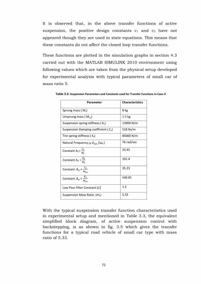
It is observed that, in the above transfer functions of active
suspension, the positive design constants c1 and c2 have not
appeared though they are used in state equations. This means that
these constants do not affect the closed loop transfer functions.
These functions are plotted in the simulation graphs in section 4.3
carried out with the MATLAB SIMULINK 2010 environment using
following values which are taken from the physical setup developed
for experimental analysis with typical parameters of small car of
mass ratio 5.
Table 3.3: Suspension Parameters and Constants used for Transfer Functions in Case-II
Parameter Characteristics
Sprung mass ( Ms) 8 kg
Unsprung mass ( Mus) 1.5 kg
Suspension spring stiffness ( Ks) 13900 N/m
Suspension Damping coefficient ( Cs) 518 Ns/m
Tire spring stiffness ( Kt) 85000 N/m
Natural Frequency Of (ω0 ) 76 rad/sec
Constant A1=
33.45
Constant A2 =
101.4
Constant =
35.23
Constant =
540.81
Low Pass Filter Constant () 1.5
Suspension Mass Ratio (mr) 5.33
With the typical suspension transfer function characteristics used
in experimental setup and mentioned in Table 3.3, the equivalent
simplified block diagram, of active suspension control with
backstepping, is as shown in fig. 3.5 which gives the transfer
functions for a typical road vehicle of small car type with mass
ratio of 5.33.

73
Fig. 3.5: Equivalent simplified block diagram, of active suspension control with backstepping
control with typical case values for mass ratio of 5.33.
These transfer functions can be determined at some invariant point
as follows:
1. At natural frequency of unsprung mass, (ω0 ) i.e. at normalized
frequency =1, transmissibility with transfer function in (31),
H1a (j 0) = = 1/5 = 0.20 which is very close to motion
transmissibility of 0.24 obtained from the Simulations of figures
4.5 and 4.6.
In the next chapter, the analysis of 2 DOF Quarter Car Passive
Suspension System (QC-PSS) and Electro-Hydraulic Active
Suspension System (QC-EH-ASS), using the theory outlined in this
chapter, is carried out by the simulation technique (Simulink and
Simscape).