chapter 3, description of the proposed project › environment › info › esa › mpwsp › ...day...
TRANSCRIPT
CalAm Monterey Peninsula Water Supply Project 3-1 ESA / 205335.01 Final EIR/EIS March 2018
CHAPTER 3 Description of the Proposed Project
Sections Tables
3.1 Introduction 3.2 Project Components 3.3 Construction 3.4 Operations and Maintenance 3.5 Permits, Approvals, and Regulatory Requirements
3-1 Facilities Summary for the Proposed Project 3-2 Length of Permanent Slant Wells Seaward of Mean
High Water Line 3-3 Desalination Chemicals and Annual Usage 3-4 Construction Staging Areas 3-5 Construction Assumptions for the Proposed Project 3-6 Overview of Typical Facility Operations for the
Proposed Project 3-7 MPWSP Desalination Plant Operations – Normal
Operations vs. Recovery Post 2-Day Shutdown 3-8 Anticipated Permits and Approvals
Figures
3-1 CalAm Monterey District Service Area 3-2 Monterey Peninsula Water Supply Project Overview
and Index Map 3-3a MPWSP Seawater Intake System 3-3b Illustrative Cross-Sectional View of Subsurface
Slant Wells 3-4 Proposed Pipelines - Lapis Road and Neponset
Road Vicinity 3-5a MPWSP Desalination Plant 3-5b MPWSP Desalination Plant – Site Plan 3-6 New Desalinated Water Pipeline
3-7 New Transmission Main - City of Marina 3-8 New Transmission Main - Light Fighter Drive to
General Jim Moore Boulevard 3-9 ASR Facilities and Terminal Reservoir 3-10 Highway 68 Interconnection Improvements and
Carmel Valley Pump Station 3-11 Castroville Pipeline 3-12 Castroville Pipeline - Connection to CCSD
Distribution System 3-13 Castroville Pipeline Optional Alignment 3-14 Site Plans: ASR-5 Well and ASR-6 Well
3.1 Introduction
3.1.1 Introduction to Project Description This chapter describes the components of the Monterey Peninsula Water Supply Project (MPWSP) proposed by the California-American Water Company (CalAm). The information in this chapter is intended to provide the reader with an understanding of the construction and operational aspects of CalAm’s proposed project1 and provide a common basis for the analysis of environmental impacts in Chapter 4, Environmental Setting (Affected Environment), Impacts, and Mitigation Measures.
1 The term “proposed project” is used when referring to CalAm’s proposed MPWSP. This term is used when discussing
impacts resulting from implementation of all federal, state, and local permits, approvals, and authorizations. The term “proposed action,” more commonly used in NEPA documents, refers specifically to MBNMS’ three federal proposed actions described in Section 1.3.2.
3. Description of the Proposed Project
CalAm Monterey Peninsula Water Supply Project 3-2 ESA / 205335.01 Final EIR/EIS March 2018
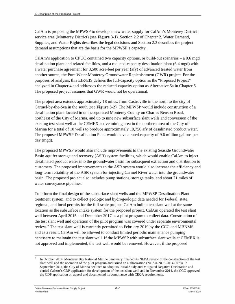
CalAm is proposing the MPWSP to develop a new water supply for CalAm’s Monterey District service area (Monterey District) (see Figure 3-1). Section 2.2 of Chapter 2, Water Demand, Supplies, and Water Rights describes the legal decisions and Section 2.3 describes the project demand assumptions that are the basis for the MPWSP’s capacity.
CalAm’s application to CPUC contained two capacity options, or build-out scenarios – a 9.6 mgd desalination plant and related facilities, and a reduced-capacity desalination plant (6.4 mgd) with a water purchase agreement for 3,500 acre-feet per year (afy) of advanced treated water from another source, the Pure Water Monterey Groundwater Replenishment (GWR) project. For the purposes of analysis, this EIR/EIS defines the full-capacity option as the “Proposed Project” analyzed in Chapter 4 and addresses the reduced-capacity option as Alternative 5a in Chapter 5. The proposed project assumes that GWR would not be operational.
The project area extends approximately 18 miles, from Castroville in the north to the city of Carmel-by-the-Sea in the south (see Figure 3-2). The MPWSP would include construction of a desalination plant located in unincorporated Monterey County on Charles Benson Road, northeast of the City of Marina, and up to nine new subsurface slant wells and conversion of the existing test slant well at the CEMEX active mining area in the northern area of the City of Marina for a total of 10 wells to produce approximately 10,750 afy of desalinated product water. The proposed MPWSP Desalination Plant would have a rated capacity of 9.6 million gallons per day (mgd).
The proposed MPWSP would also include improvements to the existing Seaside Groundwater Basin aquifer storage and recovery (ASR) system facilities, which would enable CalAm to inject desalinated product water into the groundwater basin for subsequent extraction and distribution to customers. The proposed improvements to the ASR system would also increase the efficiency and long-term reliability of the ASR system for injecting Carmel River water into the groundwater basin. The proposed project also includes pump stations, storage tanks, and about 21 miles of water conveyance pipelines.
To inform the final design of the subsurface slant wells and the MPWSP Desalination Plant treatment system, and to collect geologic and hydrogeologic data needed for Federal, state, regional, and local permits for the full-scale project, CalAm built a test slant well at the same location as the subsurface intake system for the proposed project. CalAm operated the test slant well between April 2015 and December 2017 as a pilot program to collect data. Construction of the test slant well and operation of the pilot program was covered under separate environmental review.2 The test slant well is currently permitted to February 2019 by the CCC and MBNMS, and as a result, CalAm will be allowed to conduct limited periodic maintenance pumping necessary to maintain the test slant well. If the MPWSP with subsurface slant wells at CEMEX is not approved and implemented, the test well would be removed. However, if the proposed
2 In October 2014, Monterey Bay National Marine Sanctuary finished its NEPA review of the construction of the test
slant well and the operation of the pilot program and issued an authorization (NOAA-NOS-2014-0078). In September 2014, the City of Marina declined to adopt its Initial Study and Mitigated Negative Declaration and denied CalAm’s CDP application for development of the test slant well, and in November 2014, the CCC approved the CDP application on appeal and documented its compliance with CEQA requirements.

GrovePacific
Hidden Hills*
*Ryan Ranch
Bishop*
Mo
nt e
r ey
Ba
y
Ambler*Toro*218
68
183
1
1
1
129152
156
101
68
Watsonville
Salinas
Castroville
Marina
Moss Landing
Seaside
SandCity
Carmel By The Sea
Pacific
CarmelHighlands
Carmel Valley Village
Carmel By The Sea
PacificGrove
Monterey
PebbleBeach
CarmelHighlands
Del Rey Oaks
Carmel Valley Village
Salinas River
Carmel River
Elkh
o rn
Slough
SANT
ACR
UZ CO
MONTEREY CO
SANBENITO
CO
MONTEREY
CO
Carmel Valley Rd
21868
183
1
1
1
129152
156
101
68
Watsonville
Salinas
Castroville
Marina
Moss Landing
Seaside
SandCity
Carmel By The Sea
Pacific
CarmelHighlands
Carmel Valley Village
Carmel By The Sea
PacificGrove
Monterey
PebbleBeach
CarmelHighlands
Del Rey Oaks
Carmel Valley Village
Salinas River
Carmel River
Elkh
o rn
Slough
SANT
ACR
UZ CO
MONTEREY CO
SANBENITO
CO
MONTEREY
CO
Carmel Valley Rd 0 2
Miles
N
5.01 Monterey Peninsula Water Supply ProjectFigure 3-1
CalAm Monterey District Service AreaSOURCE: ESA, 20
2053313
CalAm Service AreaMonterey Penisula Water Management District BoundaryHighway 68 Satellite Water System*
3-3

3. Description of the Proposed Project
CalAm Monterey Peninsula Water Supply Project 3-4 ESA / 205335.01 Final EIR/EIS March 2018
This page intentionally left blank
!
!
!! ASR Injection/
Extraction Wells (Proposed)
MRWPCA OceanOutfall and Diffuser (Existing)
MRWPCARegional Wastewater
Treatment Plant (Existing)
Subsurface Slant Wells (Proposed)
M o nt e
re
yB
ay
MPWSP DesalinationPlant (Proposed)
CSIPPond (Existing)
!!
Reservation Rd
Gene
ral Ji
m Mo
ore
Blvd
La Salle Ave
Hilby AveDel Monte Blvd
Main System-Hidden HillsInterconnection Improvements
(Proposed)
S a l i n a s R i v e r
Phase I ASR Facilities (Existing)
!
Phase II ASRFacilities (Existing)!
MontereyPeninsula
Airport
Carmel V alley Rd
Laure
lsGrad
e
Carmel Valley Pump Station(Proposed)
PacificGrove
Monterey
Seaside
Sand City
Del Rey Oaks
Marina
ÄÅ183
ÄÅ218
ÄÅ68
Castroville
Ryan Ranch-BishopInterconnection Improvements
(Proposed)
Connection to Existing CCSD Water
Distribution System
3 - 10a
3 - 10b
3 - 13
3 - 10c
ÄÅ1
ÄÅ1
ÄÅ68
3 - 4
3 - 8
3 - 6
3 - 3
3 - 5
3 - 12
3 - 9b
3 - 9a
3 - 7a
3 - 7b
3 - 11a
3 - 11b
205335.01 Monterey Peninsula Water Supply ProjectFigure 3-2
Monterey Peninsula Water Supply Project Overview and Index Map
Existing Slant Well
MRWPCA Ocean Outfall andand Diffuser (Existing)
Proposed Project FacilitiesSlant Well
New Transmission Main
Source Water Pipeline
Brine Discharge Pipeline
HWY 68 Interconnection Improvements
New Desalinated Water Pipeline
Castroville Pipeline
Castroville Pipeline Optional Alignment
Pipeline to CSIP Pond
ASR Pipelines *
0 2
Miles
Project Location
NOTE:*The ASR Pipelines are the ASR Conveyance Pipeline,the ASR Pump-to-Waste Pipeline, and the ASR Recirculation Pipeline. See Figure 3-9a for the individual pipeline alignments.
SOURCE: ESA, 2016
3-5

3. Description of the Proposed Project
CalAm Monterey Peninsula Water Supply Project 3-6 ESA / 205335.01 Final EIR/EIS March 2018
This page intentionally left blank
3. Description of the Proposed Project
CalAm Monterey Peninsula Water Supply Project 3-7 ESA / 205335.01 Final EIR/EIS March 2018
subsurface slant wells at CEMEX are ultimately approved as part of the proposed project or Alternative 5a, CalAm would convert the test slant well into a permanent well and operate it as part of the subsurface intake system. The conversion and long-term operation of the test slant well as a production well has not been covered under previous approvals and is evaluated in this EIR/EIS as part of the proposed project.
3.1.1.1 Source Water Components and Definitions Several terms describing source water components are used in this chapter and throughout the EIR/EIS and definitions of these terms are provided here to assist the reader. To begin with, groundwater and ocean water can be described in simple geographic, locational terms as follows:
Groundwater: water located beneath the earth’s surface.
Ocean water: water located above the seafloor.
The water chemistry indicates where the water came from (i.e., whether it started as groundwater or ocean water) and how usable it is for domestic and other purposes. In the context of the proposed MPWSP and for purposes of this EIR/EIS, the source water components are defined and used in the EIR/EIS as follows:
Fresh water: water that originated in a groundwater basin through precipitation or rivers and streams; in the context of the MPWSP, fresh water is water that originated within the Salinas Valley Groundwater Basin, identified as containing total dissolved solids (TDS) concentrations of less than 500 milligrams per liter (mg/L), consistent with the secondary drinking water standards established by the SWRCB in Title 22 California Code of Regulations, section 64449, as recommended levels of TDS. TDS is the quantity of dissolved materials in a water sample and is used to quantify the amount of salts in a sample.
Seawater: water that originated in the ocean, identified as containing 33,500 mg/L of TDS, which represents current salinity levels in Monterey Bay.
Brackish water: water that is a combination of seawater and fresh water, and thus contains TDS levels between 500 mg/L and 33,500 mg/L.
Source water (also referred to as feed water): water that would be drawn into the proposed project slant wells and conveyed to the desalination facility. This water would be a combination of brackish groundwater representing the ambient conditions in the water-bearing sediments of the Dune Sand and 180-FTE Aquifers at the coast, and the seawater that is drawn in through the aquifer sediments to recharge the capture zone. The capture zone is the localized region that would contribute source water to the slant wells.
3.1.2 Summary of Changes Made by CalAm to Project Description
Following publication of the Draft EIR/EIS, CalAm proposed several changes to the project description. These changes are reflected in this chapter and in the analysis throughout this Final EIR/EIS. Changes include:

3. Description of the Proposed Project
CalAm Monterey Peninsula Water Supply Project 3-8 ESA / 205335.01 Final EIR/EIS March 2018
• Removal of the Terminal Reservoir from the proposed project (no longer proposed by CalAm);
• Removal of pump capacity upgrades at Upper Tierra Grande Booster Station from the proposed project (no longer proposed by CalAm);
• Addition of Brine Mixing Box and appurtenances to Brine Disposal Facilities based on discussions with Monterey Regional Water Pollution Control Agency;
• Clarification of Brine Discharge Pipeline diameter (36 inches rather than 30 inches);
• Clarification of pre-treatment building size (4,000 square feet rather than 6,000 square feet)
Other changes have been made throughout the document as a result of public comment and authors’ changes. These are described in the introduction to topical sections in Chapter 4.
3.2 Project Components The MPWSP comprises the following facilities:
• The source water intake system, which would consist of 10 subsurface slant wells3 (eight active and two on standby) extending into submerged lands of Monterey Bay National Marine Sanctuary (MBNMS), and a Source Water Pipeline
• A full build out 9.6 mgd desalination plant option and related facilities, including pretreatment, reverse osmosis (RO), and post-treatment systems; backwash supply and filtered water equalization tanks; treated water storage tanks; chemical feed and storage facilities; brine storage and conveyance facilities; and other associated non-process facilities
• Desalinated water conveyance facilities including pipelines and a stand-alone pump station
• An expanded ASR system, including two additional injection/extraction wells, the ASR-5 and ASR-6 Wells, and three parallel pipelines, the ASR Conveyance Pipeline, ASR Pump-to-Waste Pipeline, and ASR Recirculation Pipeline. These expanded pipelines would convey water to and from the new ASR injection/extraction wells and backwash effluent from the wells to an existing settling basin
Table 3-1 summarizes the proposed MPWSP facilities; for detailed descriptions of the facilities and definitions of technical terms contained in Table 3-1, see Sections 3.2.1 through 3.4. As discussed in Section 1.1, Introduction, CalAm’s application for the proposed project also includes an option that would meet all of the project objectives by combining a reduced-capacity desalination plant (6.4 mgd) with a water purchase agreement for 3,500 acre-feet per year (afy) of advanced treated water from another source, the GWR project. That option is discussed in Chapter 5 as Alternative 5; the project description for the GWR is provided as EIR/EIS Appendix H.
3 The existing test slant well would be converted into a permanent well, and nine additional slant wells would be
built.
3. Description of the Proposed Project
CalAm Monterey Peninsula Water Supply Project 3-9 ESA / 205335.01 Final EIR/EIS March 2018
TABLE 3-1 FACILITIES SUMMARY FOR THE PROPOSED PROJECT
Facility Description Purpose
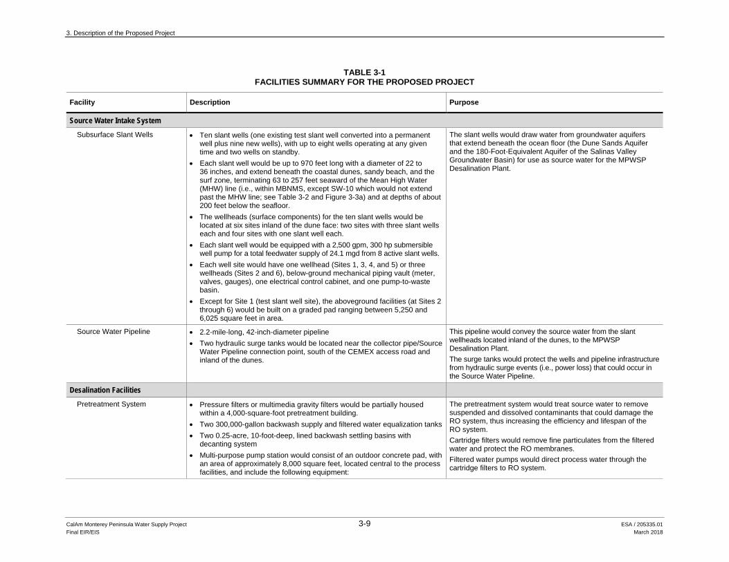
Source Water Intake System Subsurface Slant Wells • Ten slant wells (one existing test slant well converted into a permanent
well plus nine new wells), with up to eight wells operating at any given time and two wells on standby.
• Each slant well would be up to 970 feet long with a diameter of 22 to 36 inches, and extend beneath the coastal dunes, sandy beach, and the surf zone, terminating 63 to 257 feet seaward of the Mean High Water (MHW) line (i.e., within MBNMS, except SW-10 which would not extend past the MHW line; see Table 3-2 and Figure 3-3a) and at depths of about 200 feet below the seafloor.
• The wellheads (surface components) for the ten slant wells would be located at six sites inland of the dune face: two sites with three slant wells each and four sites with one slant well each.
• Each slant well would be equipped with a 2,500 gpm, 300 hp submersible well pump for a total feedwater supply of 24.1 mgd from 8 active slant wells.
• Each well site would have one wellhead (Sites 1, 3, 4, and 5) or three wellheads (Sites 2 and 6), below-ground mechanical piping vault (meter, valves, gauges), one electrical control cabinet, and one pump-to-waste basin.
• Except for Site 1 (test slant well site), the aboveground facilities (at Sites 2 through 6) would be built on a graded pad ranging between 5,250 and 6,025 square feet in area.
The slant wells would draw water from groundwater aquifers that extend beneath the ocean floor (the Dune Sands Aquifer and the 180-Foot-Equivalent Aquifer of the Salinas Valley Groundwater Basin) for use as source water for the MPWSP Desalination Plant.
Source Water Pipeline • 2.2-mile-long, 42-inch-diameter pipeline • Two hydraulic surge tanks would be located near the collector pipe/Source
Water Pipeline connection point, south of the CEMEX access road and inland of the dunes.
This pipeline would convey the source water from the slant wellheads located inland of the dunes, to the MPWSP Desalination Plant. The surge tanks would protect the wells and pipeline infrastructure from hydraulic surge events (i.e., power loss) that could occur in the Source Water Pipeline.
Desalination Facilities Pretreatment System • Pressure filters or multimedia gravity filters would be partially housed
within a 4,000-square-foot pretreatment building. • Two 300,000-gallon backwash supply and filtered water equalization tanks • Two 0.25-acre, 10-foot-deep, lined backwash settling basins with
decanting system • Multi-purpose pump station would consist of an outdoor concrete pad, with
an area of approximately 8,000 square feet, located central to the process facilities, and include the following equipment:
The pretreatment system would treat source water to remove suspended and dissolved contaminants that could damage the RO system, thus increasing the efficiency and lifespan of the RO system. Cartridge filters would remove fine particulates from the filtered water and protect the RO membranes. Filtered water pumps would direct process water through the cartridge filters to RO system.

3. Description of the Proposed Project
TABLE 3-1 (Continued) FACILITIES SUMMARY FOR THE PROPOSED PROJECT
CalAm Monterey Peninsula Water Supply Project 3-10 ESA / 205335.01 Final EIR/EIS March 2018
Facility Description Purpose
Desalination Facilities (cont.) Pretreatment System (cont.) − Seven cartridge filters
− Four filtered water pumps: Two 12-mgd, 350-horsepower (hp) pumps, and two 6-mgd, 200-hp pumps
− Two backwash supply pumps (16 mgd, 150 hp each)
Backwash supply pumps would be used to clean the media in the pressure filters.
Reverse Osmosis (RO) System • First-pass seawater RO system comprising seven modules (six active and one standby), with each module producing 1.6 mgd of “permeate,” that is, the purified water produced through the RO membrane.
• Partial second-pass brackish water RO system comprising four modules (three duty and one standby), with each module producing 1.3 mgd of permeate.
• The RO units and cleaning systems and chemical storage tanks would be housed within a 30,000-square-foot process and electrical building (membrane process building).
The RO system would remove salts and other minerals from pretreated source water.
Post-treatment System • Ultraviolet disinfection system (if required) comprising three reactors (two active and one standby) that would be housed in the membrane process building.
• Carbon dioxide system comprising one 120-ton storage tank and feed equipment in a concrete enclosure that would be located next to membrane process building
• Lime system comprising two 20,000-gallon storage tanks and feed equipment in a concrete enclosure that would be located next to membrane process building
If required by the State Water Resources Control Board (SWRCB) Division of Drinking Water, the UV Disinfection system would provide additional primary disinfection. The carbon dioxide and lime systems would adjust the hardness, pH, and alkalinity of the desalinated product water in accordance with drinking water requirements.
Chemical Storage (Membrane Process Building)
The following treatment chemicals would be housed in the membrane process building. The storage tanks/drums would sit on concrete stalls with secondary containment curbs to contain inadvertent spills of hazardous treatment chemicals: • Sodium hypochlorite - two 6,500-gallon storage tanks • Sodium hydroxide - one 5,200-gallon tank • Sulfuric acid -one 10,000-gallon tank • Sodium bisulfite - one 6,000-gallon tank • Zinc orthophosphate -one 5,600-gallon tank • Anti-scalant - one 6,300-gallon tank • Non-ionic polymer – multiple 55-gallon drums
The sodium hypochlorite system would generate low-concentration chlorine solution using salt and electricity; and the chlorine would provide primary and residual disinfection for drinking water. The sodium hydroxide system would adjust the pH and alkalinity of the desalinated product water and disinfect the water in accordance with drinking water requirements. The sulfuric acid system would be used to clean the RO membranes. The sodium bisulfite system would be used to dechlorinate process waters and brine in the treatment, cleaning and disposal processes. The zinc orthophosphate system would be used as a corrosion inhibitor in the treated water to protect the distribution system.
3. Description of the Proposed Project
TABLE 3-1 (Continued) FACILITIES SUMMARY FOR THE PROPOSED PROJECT
CalAm Monterey Peninsula Water Supply Project 3-11 ESA / 205335.01 Final EIR/EIS March 2018
Facility Description Purpose
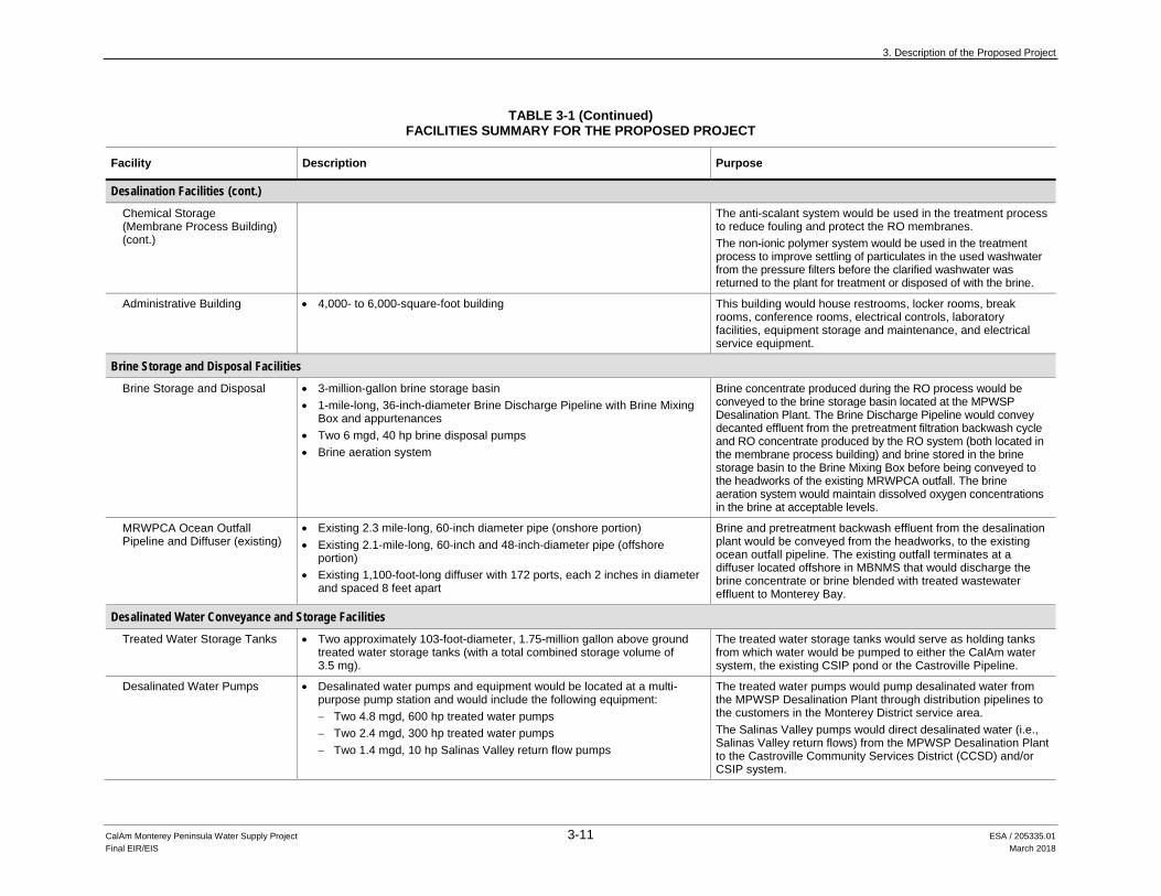
Desalination Facilities (cont.) Chemical Storage (Membrane Process Building) (cont.)
The anti-scalant system would be used in the treatment process to reduce fouling and protect the RO membranes. The non-ionic polymer system would be used in the treatment process to improve settling of particulates in the used washwater from the pressure filters before the clarified washwater was returned to the plant for treatment or disposed of with the brine.
Administrative Building • 4,000- to 6,000-square-foot building This building would house restrooms, locker rooms, break rooms, conference rooms, electrical controls, laboratory facilities, equipment storage and maintenance, and electrical service equipment.
Brine Storage and Disposal Facilities Brine Storage and Disposal • 3-million-gallon brine storage basin
• 1-mile-long, 36-inch-diameter Brine Discharge Pipeline with Brine Mixing Box and appurtenances
• Two 6 mgd, 40 hp brine disposal pumps • Brine aeration system
Brine concentrate produced during the RO process would be conveyed to the brine storage basin located at the MPWSP Desalination Plant. The Brine Discharge Pipeline would convey decanted effluent from the pretreatment filtration backwash cycle and RO concentrate produced by the RO system (both located in the membrane process building) and brine stored in the brine storage basin to the Brine Mixing Box before being conveyed to the headworks of the existing MRWPCA outfall. The brine aeration system would maintain dissolved oxygen concentrations in the brine at acceptable levels.
MRWPCA Ocean Outfall Pipeline and Diffuser (existing)
• Existing 2.3 mile-long, 60-inch diameter pipe (onshore portion) • Existing 2.1-mile-long, 60-inch and 48-inch-diameter pipe (offshore
portion) • Existing 1,100-foot-long diffuser with 172 ports, each 2 inches in diameter
and spaced 8 feet apart
Brine and pretreatment backwash effluent from the desalination plant would be conveyed from the headworks, to the existing ocean outfall pipeline. The existing outfall terminates at a diffuser located offshore in MBNMS that would discharge the brine concentrate or brine blended with treated wastewater effluent to Monterey Bay.
Desalinated Water Conveyance and Storage Facilities Treated Water Storage Tanks • Two approximately 103-foot-diameter, 1.75-million gallon above ground
treated water storage tanks (with a total combined storage volume of 3.5 mg).
The treated water storage tanks would serve as holding tanks from which water would be pumped to either the CalAm water system, the existing CSIP pond or the Castroville Pipeline.
Desalinated Water Pumps • Desalinated water pumps and equipment would be located at a multi-purpose pump station and would include the following equipment: − Two 4.8 mgd, 600 hp treated water pumps − Two 2.4 mgd, 300 hp treated water pumps − Two 1.4 mgd, 10 hp Salinas Valley return flow pumps
The treated water pumps would pump desalinated water from the MPWSP Desalination Plant through distribution pipelines to the customers in the Monterey District service area. The Salinas Valley pumps would direct desalinated water (i.e., Salinas Valley return flows) from the MPWSP Desalination Plant to the Castroville Community Services District (CCSD) and/or CSIP system.

3. Description of the Proposed Project
TABLE 3-1 (Continued) FACILITIES SUMMARY FOR THE PROPOSED PROJECT
CalAm Monterey Peninsula Water Supply Project 3-12 ESA / 205335.01 Final EIR/EIS March 2018
Facility Description Purpose
Desalinated Water Conveyance and Storage Facilities (cont.) New Desalinated Water Pipeline • 3.3-mile-long, 36-inch-diameter pipeline This pipeline would convey desalinated water from the treated
water storage tanks at the MPWSP Desalination Plant to the new Transmission Main at Reservation Road.
New Transmission Main • 6-mile-long, 36-inch-diameter pipeline This pipeline would convey desalinated water between the new Desalinated Water Pipeline at Reservation Road, crossing U.S. Army-owned property along General Jim Moore Blvd. to the existing Phase I ASR Facilities where it would connect to CalAm’s existing water supply distribution system at the General Jim Moore Boulevard/Coe Avenue intersection.
Carmel Valley Pump Station • 3 mgd, 100 hp pump station This 500-square-foot facility would provide the additional water pressure needed to pump water through the existing Segunda Pipeline into Segunda Reservoir.
Interconnection Improvements for Highway 68 Satellite Systems a) Ryan Ranch–Bishop
Interconnection b) Main System–Hidden Hills
Interconnection
• 1.1-mile-long, 8-inch-diameter pipeline • 1,200-foot-long, 6-inch-diameter pipeline • One new 350 gpm pump
These interconnection pipelines and associated improvements would allow CalAm to convey MPWSP water supplies to the Ryan Ranch, Bishop, and Hidden Hills satellite water systems.
Castroville Pipeline • 4.5-mile-long, 12 inch-diameter pipeline extending from MPWSP Desalination Plant to Castroville (see Figures 3-11 and 3-12)
This pipeline would convey desalinated water from the MPWSP Desalination Plant to the Castroville Seawater Intrusion Project (CSIP) distribution system and the CCSD Well #3. Desalinated water would be delivered to the CSIP system via a new connection point located approximately halfway along the pipeline alignment at Nashua Road and Monte Road. At the northern pipeline terminus, desalinated water would be delivered to the CCSD Well #3 at Del Monte Avenue and Merritt Street.
Pipeline to CSIP Pond • 1.2-mile-long, 12-inch-diameter pipeline (see Figure 3-5) This pipeline would convey desalinated water from the MPWSP Desalination Plant to the CSIP pond for subsequent delivery to agricultural users in the Salinas Valley.
ASR System Two new ASR Injection/Extraction Wells, referred to as ASR-5 and ASR-6 Wells
• Two proposed 1,000-foot-deep injection/extraction wells (ASR-5 and ASR-6 Wells) with a combined injection capacity of 2.2 mgd and extraction capacity of 4.3 mgd
The proposed new ASR injection/extraction wells would be used to inject Carmel River supplies and desalinated water into the Seaside Groundwater Basin for storage. The two proposed ASR wells would be located on U.S. Army-owned property in the Fitch Park neighborhood of the Ord Military Community. The four existing ASR wells would also be used for these purposes. During periods of peak demand, the stored water would be extracted and delivered to customers.
3. Description of the Proposed Project
TABLE 3-1 (Continued) FACILITIES SUMMARY FOR THE PROPOSED PROJECT
CalAm Monterey Peninsula Water Supply Project 3-13 ESA / 205335.01 Final EIR/EIS March 2018
Facility Description Purpose
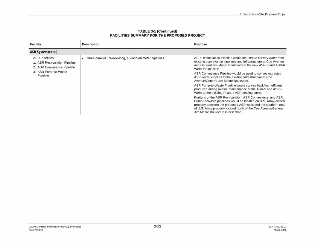
ASR System (cont.) ASR Pipelines: 1. ASR Recirculation Pipeline 2. ASR Conveyance Pipeline 3. ASR Pump-to-Waste
Pipeline
• Three parallel 0.9-mile-long, 16-inch-diameter pipelines ASR Recirculation Pipeline would be used to convey water from existing conveyance pipelines and infrastructure at Coe Avenue and General Jim Moore Boulevard to the new ASR-5 and ASR-6 Wells for injection. ASR Conveyance Pipeline would be used to convey extracted ASR water supplies to the existing infrastructure at Coe Avenue/General Jim Moore Boulevard. ASR Pump-to-Waste Pipeline would convey backflush effluent produced during routine maintenance of the ASR-5 and ASR-6 Wells to the existing Phase I ASR settling basin. Portions of the ASR Recirculation, ASR Conveyance, and ASR Pump-to-Waste pipelines would be located on U.S. Army-owned property between the proposed ASR wells and the southern end of U.S. Army property located north of the Coe Avenue/General Jim Moore Boulevard intersection.

3. Description of the Proposed Project
CalAm Monterey Peninsula Water Supply Project 3-14 ESA / 205335.01 Final EIR/EIS March 2018
This page intentionally left blank
MRWPCA Ocean Outfall Pipeline (Existing)
C i t y o fM a r i n a
C o u n t yo f M o n t e r e y
CEMEX Dredging Pond
CEMEX Settling Ponds
Test Slant Well(Existing)
Mo n
t er e
y P
e ni n
s ul a
Re c
r ea t
i on a
l T r
a il
WS-1
WS-2
WS-3
WS-4
WS-5
WS-6
Graded Access Road(Proposed)
MHW 2020MHW 2030
MHW 2040MHW 2060
SW-1
SW-3
SW-4
SW-5
SW-6
SW-7
SW-8
SW-9
SW-10
SW-2
Surge TankLocation 1
Surge TankLocation 2
HDD PipelineRoute
UV1
Del M
onte
Blvd
Lapis
Rd
M a t c h L i n e
205335.01 Monterey Peninsula Water Supply ProjectFigure 3-3a
MPWSP Seawater Intake SystemSOURCE: ESA, 2016
Trenchless Construction Ingress PitTrenchless Construction Egress PitCity BoundaryTest Slant Well (Existing)Project Area Boundary *
Proposed FacilitiesWell SiteSlant WellNew Desalinated Water PipelineSource Water Pipeline
Mean High Water (MHW)2020203020402060
0 550
Feet
l
C E M E X S a n d
M i n i n g F a c i l i t y
NOTE:*Project area boundary refers to the area within which all construction related disturbance would occur.
A'
A
Typical WellSite Layout
Mechanical Piping (14' x 8')Pump-to-Waste Basin (Rip Rap)
ElectricalEnclosure(18' x 11' x 10')
Graded Area5,250 - 6,025 sq ft
*Components shown in grayare for sites with 3 slant wells(WS-2 and WS-6)
ConcretePad
12' x 8'
3-15

3. Description of the Proposed Project
CalAm Monterey Peninsula Water Supply Project 3-16 ESA / 205335.01 Final EIR/EIS March 2018
This page intentionally left blank
3. Description of the Proposed Project
3.2.1 Source Water Intake System
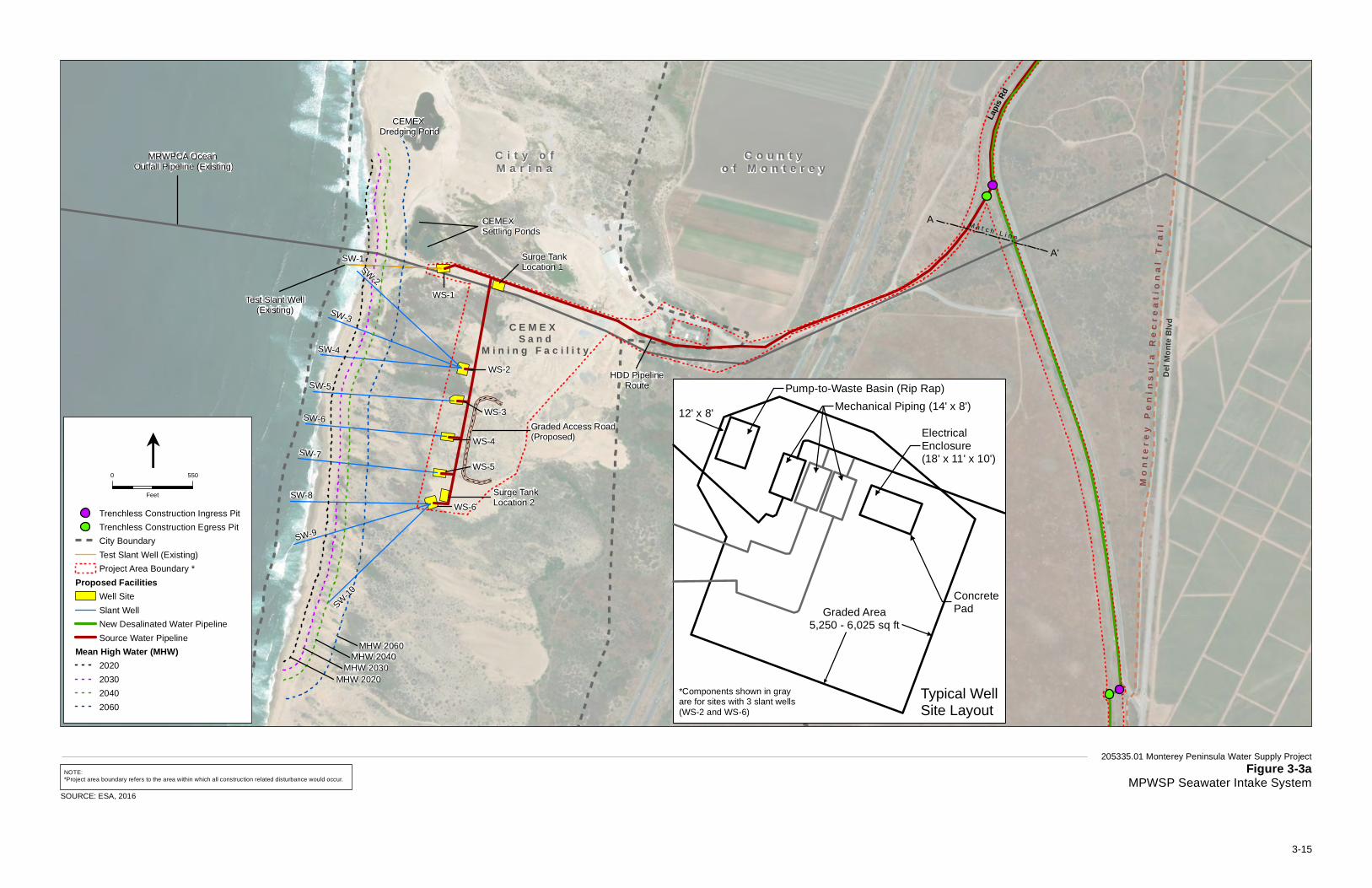
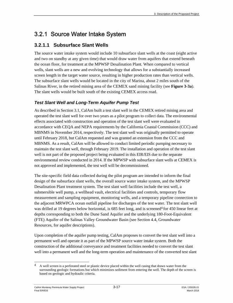
3.2.1.1 Subsurface Slant Wells The source water intake system would include 10 subsurface slant wells at the coast (eight active and two on standby at any given time) that would draw water from aquifers that extend beneath the ocean floor, for treatment at the MPWSP Desalination Plant. When compared to vertical wells, slant wells are a new and evolving technology that allows for a substantially increased screen length in the target water source, resulting in higher production rates than vertical wells. The subsurface slant wells would be located in the city of Marina, about 2 miles south of the Salinas River, in the retired mining area of the CEMEX sand mining facility (see Figure 3-3a). The slant wells would be built south of the existing CEMEX access road.
Test Slant Well and Long-Term Aquifer Pump Test
As described in Section 3.1, CalAm built a test slant well in the CEMEX retired mining area and operated the test slant well for over two years as a pilot program to collect data. The environmental effects associated with construction and operation of the test slant well were evaluated in accordance with CEQA and NEPA requirements by the California Coastal Commission (CCC) and MBNMS in November 2014, respectively. The test slant well was originally permitted to operate until February 2018, but CalAm requested and was granted an extension from the CCC and MBNMS. As a result, CalAm will be allowed to conduct limited periodic pumping necessary to maintain the test slant well, through February 2019. The installation and operation of the test slant well is not part of the proposed project being evaluated in this EIR/EIS due to the separate environmental review conducted in 2014. If the MPWSP with subsurface slant wells at CEMEX is not approved and implemented, the test well will be decommissioned.
The site-specific field data collected during the pilot program are intended to inform the final design of the subsurface slant wells, the overall source water intake system, and the MPWSP Desalination Plant treatment system. The test slant well facilities include the test well, a submersible well pump, a wellhead vault, electrical facilities and controls, temporary flow measurement and sampling equipment, monitoring wells, and a temporary pipeline connection to the adjacent MRWPCA ocean outfall pipeline for discharges of the test water. The test slant well was drilled at 19 degrees below horizontal, is 685 feet long, and is screened4 for 450 linear feet at depths corresponding to both the Dune Sand Aquifer and the underlying 180-Foot-Equivalent (FTE) Aquifer of the Salinas Valley Groundwater Basin (see Section 4.4, Groundwater Resources, for aquifer descriptions).
Upon completion of the aquifer pump testing, CalAm proposes to convert the test slant well into a permanent well and operate it as part of the MPWSP source water intake system. Both the construction of the additional conveyance and treatment facilities needed to convert the test slant well into a permanent well and the long-term operation and maintenance of the converted test slant
A well screen is a perforated steel or plastic device placed within the well casing that draws water from the surrounding geologic formations but which minimizes sediment from entering the well. The depth of the screen is based on geologic and hydraulic criteria.
CalAm Monterey Peninsula Water Supply Project 3-17 ESA / 205335.01 Final EIR/EIS March 2018
4
3. Description of the Proposed Project
CalAm Monterey Peninsula Water Supply Project 3-18 ESA / 205335.01 Final EIR/EIS March 2018
well are part of the proposed project, and are thus evaluated in this EIR/EIS. Sections 3.2.1.2 through 3.2.2.6, below, describe the conveyance and treatment facilities for the source water produced at the subsurface slant wells during long-term operations.
Permanent Slant Wells Each of the 10 subsurface slant wells (the converted test slant well and nine new wells) would have a submersible pump to provide a total combined 24.1 mgd of feedwater when eight wells are operating. The slant wells would be drilled from an onshore location and would extend under the seafloor within MBNMS using a 36-inch- to 22-inch-diameter steel casing. The completed pump columns and wellheads would be 10 to 12 inches in diameter.
The nine new permanent slant wells would be up to 970 feet long and drilled at approximately 14 degrees below horizontal to extend offshore to a distance of 63 (Slant Well-2) to 257 (Slant Well-8) feet seaward of the 2020 MHW line (except #10, which would not extend past the MHW line) and to a depth of 190 to 210 feet beneath the seafloor. This means that although all construction activities and ground disturbance would occur above mean sea level and landward of the MHW line, the well casings would extend subsurface and seaward of the MHW line and below the seafloor within MBNMS. Each well would be screened for approximately 400 to 800 linear feet at depths corresponding to both the Dune Sand Aquifer and the underlying 180-Foot-Equivalent (FTE) Aquifer of the Salinas Valley Groundwater Basin. CalAm would operate eight wells at a time at approximately 2,100 gallons per minute (gpm) per well and maintain the other two wells on standby.
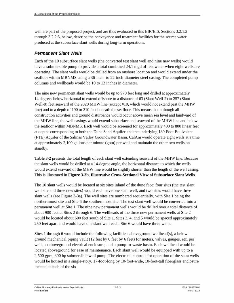
Table 3-2 presents the total length of each slant well extending seaward of the MHW line. Because the slant wells would be drilled at a 14-degree angle, the horizontal distance to which the wells would extend seaward of the MHW line would be slightly shorter than the length of the well casing. This is illustrated in Figure 3-3b, Illustrative Cross-Sectional View of Subsurface Slant Wells.
The 10 slant wells would be located at six sites inland of the dune face: four sites (the test slant well site and three new sites) would each have one slant well, and two sites would have three slant wells (see Figure 3-3a). The well sites are numbered sequentially, with Site 1 being the northernmost site and Site 6 the southernmost site. The test slant well would be converted into a permanent well at Site 1. The nine new permanent wells would be drilled over a total distance of about 900 feet at Sites 2 through 6. The wellheads of the three new permanent wells at Site 2 would be located about 600 feet south of Site 1. Sites 3, 4, and 5 would be spaced approximately 250 feet apart and would have one slant well each. Site 6 would have three wells.
Sites 1 through 6 would include the following facilities: aboveground wellhead(s), a below-ground mechanical piping vault (12 feet by 6 feet by 6 feet) for meters, valves, gauges, etc. per well, an aboveground electrical enclosure, and a pump-to-waste basin. Each wellhead would be located aboveground for ease of maintenance. Each slant well would be equipped with up to a 2,500 gpm, 300 hp submersible well pump. The electrical controls for operation of the slant wells would be housed in a single-story, 17-foot-long by 10-foot-wide, 10-foot-tall fiberglass enclosure located at each of the six

3. Description of the Proposed Project
CalAm Monterey Peninsula Water Supply Project 3-19 ESA / 205335.01 Final EIR/EIS March 2018
TABLE 3-2 LENGTH OF PERMANENT SLANT WELLS SEAWARD OF MEAN HIGH WATER LINE
Well Total
Length
2020 2040 2060
Offshore Onshore Offshore Onshore Offshore Onshore
Test Slant Well, SW-1 685 166 519 290 395 423 262
SW-2 970 63 907 219 751 385 585
SW-3 966 202 764 325 641 455 511
SW-4 961 162 799 292 669 431 530
SW-5 961 130 831 254 707 385 576
SW-6 961 174 787 298 663 428 533
SW-7 957 225 732 347 610 479 478
SW-8 955 257 698 379 576 510 445
SW-9 970 228 742 357 613 500 470
SW-10 970 0 970 0 970 262 708 NOTES: All lengths in feet.
MHW = Mean high water - A tidal datum. The average of all the high water heights observed over the National Tidal Datum Epoch. The 2020 MHW at the Monterey Tide Gauge NOAA#9413450 equals 1.53 m (5.02 ft) NAVD88, considering a high sea level rise scenario of 8.1 cm (3.2 in) by 2020 (5.46 ft by 2100). See also Appendices C1 and C2.
The lengths provided in this table indicate the total length of the well casing extending seaward of the MHW line. Because the slant wells would be drilled at an approximately 14-degree angle, the total horizontal distance seaward of the MHW line would be slightly shorter than the length of the well casing. The total horizontal distance seaward of the MHW line can be determined by dividing the length by 1.03.
SOURCE: Geoscience, 2017
well sites. Each site would also have a pump-to-waste basin for the percolation of turbid water produced during slant well startup and shutdown. The pump-to-waste basin would be constructed of rip rap material, approximately 1 to 2 feet deep and 12 feet by 8 feet in size. The new permanent slant wells and associated infrastructure at Sites 2 through 6 would be constructed on a 5,250- to 6,025-square-foot graded pad. A 750-foot-long, 42-inch-diameter buried pipe would collect the source water pumped from Sites 2 to 6 and convey it to the proposed buried Source Water Pipeline located at the existing CEMEX access road.
3.2.1.2 Source Water Pipeline The approximately 2.2-mile-long, 42-inch-diameter buried Source Water Pipeline would convey the source water from the well sites to the MPWSP Desalination Plant at Charles Benson Road. From the slant wells, the proposed Source Water Pipeline would generally follow the CEMEX access road and would run parallel to the MRWPCA’s existing outfall pipeline for approximately 0.7 mile (see Figure 3-3a). Approximately 500 feet east of Highway 1, the Source Water Pipeline would veer northeast along a dirt path for roughly 1,000 feet to Lapis Road. There, a jack and bore method would be used to install the pipeline under the existing railroad tracks. The alignment would continue north within the Transportation Agency for Monterey County (TAMC) right-of-way (ROW), along Lapis Road for about 0.5 mile. Just south of where Lapis Road meets Del Monte Boulevard, the pipeline would turn east across Del Monte Boulevard and continue east
O c e a n
MeanHighWater
Beach
Dune Sand
NOT TO SCALE
WEST
WellheadElevationApprox. 11ftAbove GroundSurface
519-970 feetWell Length
Onshore
0-257 feetWell Length
Offshore
Well Length 685 - 970 feet
205335.01 Monterey Peninsula Water Supply Project Figure 3-3b
Illustrative Cross-Sectional View ofSubsurface Slant Wells
SOURCE: Geoscience, 2017
3-20
3. Description of the Proposed Project
CalAm Monterey Peninsula Water Supply Project 3-21 ESA / 205335.01 Final EIR/EIS March 2018
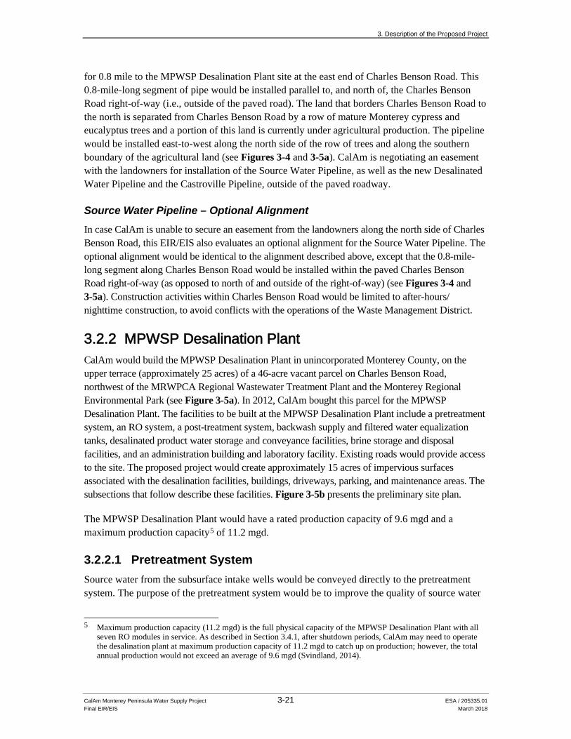
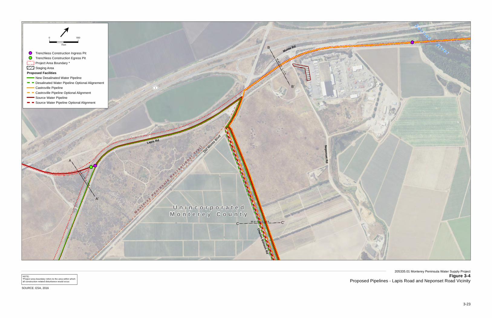
for 0.8 mile to the MPWSP Desalination Plant site at the east end of Charles Benson Road. This 0.8-mile-long segment of pipe would be installed parallel to, and north of, the Charles Benson Road right-of-way (i.e., outside of the paved road). The land that borders Charles Benson Road to the north is separated from Charles Benson Road by a row of mature Monterey cypress and eucalyptus trees and a portion of this land is currently under agricultural production. The pipeline would be installed east-to-west along the north side of the row of trees and along the southern boundary of the agricultural land (see Figures 3-4 and 3-5a). CalAm is negotiating an easement with the landowners for installation of the Source Water Pipeline, as well as the new Desalinated Water Pipeline and the Castroville Pipeline, outside of the paved roadway.
Source Water Pipeline – Optional Alignment In case CalAm is unable to secure an easement from the landowners along the north side of Charles Benson Road, this EIR/EIS also evaluates an optional alignment for the Source Water Pipeline. The optional alignment would be identical to the alignment described above, except that the 0.8-mile-long segment along Charles Benson Road would be installed within the paved Charles Benson Road right-of-way (as opposed to north of and outside of the right-of-way) (see Figures 3-4 and 3-5a). Construction activities within Charles Benson Road would be limited to after-hours/nighttime construction, to avoid conflicts with the operations of the Waste Management District.
3.2.2 MPWSP Desalination Plant CalAm would build the MPWSP Desalination Plant in unincorporated Monterey County, on the upper terrace (approximately 25 acres) of a 46-acre vacant parcel on Charles Benson Road, northwest of the MRWPCA Regional Wastewater Treatment Plant and the Monterey Regional Environmental Park (see Figure 3-5a). In 2012, CalAm bought this parcel for the MPWSP Desalination Plant. The facilities to be built at the MPWSP Desalination Plant include a pretreatment system, an RO system, a post-treatment system, backwash supply and filtered water equalization tanks, desalinated product water storage and conveyance facilities, brine storage and disposal facilities, and an administration building and laboratory facility. Existing roads would provide access to the site. The proposed project would create approximately 15 acres of impervious surfaces associated with the desalination facilities, buildings, driveways, parking, and maintenance areas. The subsections that follow describe these facilities. Figure 3-5b presents the preliminary site plan.
The MPWSP Desalination Plant would have a rated production capacity of 9.6 mgd and a maximum production capacity5 of 11.2 mgd.
3.2.2.1 Pretreatment System Source water from the subsurface intake wells would be conveyed directly to the pretreatment system. The purpose of the pretreatment system would be to improve the quality of source water
5 Maximum production capacity (11.2 mgd) is the full physical capacity of the MPWSP Desalination Plant with all
seven RO modules in service. As described in Section 3.4.1, after shutdown periods, CalAm may need to operate the desalination plant at maximum production capacity of 11.2 mgd to catch up on production; however, the total annual production would not exceed an average of 9.6 mgd (Svindland, 2014).

3. Description of the Proposed Project
CalAm Monterey Peninsula Water Supply Project 3-22 ESA / 205335.01 Final EIR/EIS March 2018
being treated by the RO system, described in Section 3.2.2.2, below, in order to increase the efficiency of RO treatment. The pretreatment requirements for seawater collected by the proposed slant wells will be determined through the operation of the test slant well and pilot program, and would include pressure filters or multimedia gravity filters, a backwash supply storage tank, and backwash settling basins. The pretreatment system could also include coagulation, flocculation,6 or membrane filtration. The pretreatment system would have the capacity to process 24.1 mgd of seawater.
The pressure filters or multimedia gravity filters would be located within the MPWSP Desalination Plant site. If pressure filters are used, multiple parallel fiberglass or lined steel tanks would be partially enclosed in a 30-foot-tall, 4,000-square-foot building. If gravity filters are used, they would be installed in below-grade, multi-cell concrete structures. A low dosage of chlorine would be added to the source water to separate out iron and manganese, and the precipitate would be removed by the filters. In addition, the pretreatment system could play an important role in pathogen removal. Because a portion of the source water supply would be groundwater under the influence of surface water as defined under the U.S. Environmental Protection Agency (USEPA) Surface Water Treatment Rule,7 the source water would be subject to the Surface Water Treatment Rule and the Long-Term 2 Enhanced Surface Water Treatment Rule.
The pretreatment process would produce approximately 23.6 mgd of pretreated, filtered source water. The pretreated source water would be conveyed to two 300,000-gallon backwash supply and filtered water equalization tanks. The majority of the pretreated source water would then be pumped directly to the RO system (see Section 3.2.2.2, below).
Pretreatment filters would require backwashing about once each day. A portion of the pretreated source water would be used for this purpose. The backwash supply water would be conveyed from the backwash supply and filtered water equalization tanks to the pretreatment filters by gravity flow. Chlorine may be added to the backwash supply to control bacterial growth on the filters.
Waste effluent produced during routine backwashing would flow via gravity from the pretreatment filters to two 0.25-acre, 6-foot-deep open backwash settling basins with impermeable liners to prevent the waste effluent from infiltrating into the ground. Suspended solids in the waste effluent would settle to the bottom of the basins, and the clarified water would be decanted. Approximately 0.4 mgd of decanted and dechlorinated backwash water would be blended with brine produced by the RO system, and discharged to the existing MRWPCA ocean outfall and diffuser for disposal into the waters of MBNMS. The decanted backwash water could be blended with source water before undergoing pretreatment and the RO process. Sludge formed by the solids in the waste effluent would be periodically removed from the backwash settling basins and disposed of at a sanitary landfill.
6 Flocculation is a process used to separate suspended solids from water. Flocculation involves the addition of an
agent to water to promote the aggregation of suspended solids into particles large enough to settle or be removed. 7 The USEPA Surface Water Treatment Rule (40 CFR 141.70-141.75) seeks to prevent waterborne diseases caused
by viruses, Legionella, and Giardia lamblia. The rule requires that water systems filter and disinfect water from surface water sources to reduce the occurrence of unsafe levels of these microbes.
Del Monte B
lvd
A'
A
B'
B
C'C
M o n t e r e y P e n i n s u l a R e c r e a t i o n a l T r a i l
U n i n c o r p o r a t e d
M o n t e r e y C o u n t yU n i n c o r p o r a t e d
M o n t e r e y C o u n t y
S a l i n a sR i v e r
Neponset Rd
UV1
UV1
Charles Benson Rd
Lapis Rd
Neponset Rd
Monte Rd
UV1
Ma
t c h L
i ne
Ma
t ch
Li n
e
M a t c h L i n e
205335.01 Monterey Peninsula Water Supply ProjectFigure 3-4
Proposed Pipelines - Lapis Road and Neponset Road VicinitySOURCE: ESA, 2016
Trenchless Construction Ingress PitTrenchless Construction Egress PitProject Area Boundary *Staging Area
Proposed FacilitiesNew Desalinated Water PipelineDesalinated Water Pipeline Optional AlignementCastroville PipelineCastroville Pipeline Optional AlignmentSource Water PipelineSource Water Pipeline Optional Alignment
0 550
Feet
l
NOTE:*Project area boundary refers to the area within whichall construction related disturbance would occur.
3-23
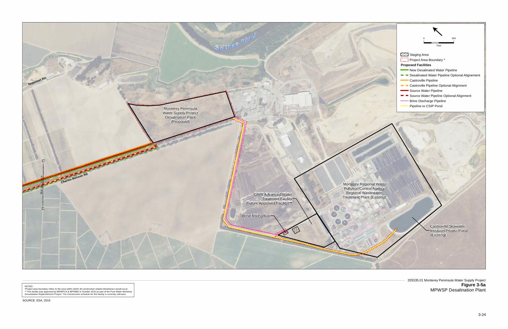
S a l i n a s R i v e r
Brine Mixing Box
GWR Advanced WaterTreatment Facility
(Future Approved Facility)**
Monterey Regional WaterPollution Control Agency
Regional Wastewater Treatment Plant (Existing)
Monterey PeninsulaWater Supply Project
Desalination Plant(Proposed)
Neponset Rd
Castroville SeawaterIntrusion Project Pond(Existing)
Charles Benson Rd
Neponset Rd
Ma
t ch
Li n
e
205335.01 Monterey Peninsula Water Supply ProjectFigure 3-5a
MPWSP Desalination Plant
SOURCE: ESA, 2016
Staging AreaProject Area Boundary *
Proposed FacilitiesNew Desalinated Water PipelineDesalinated Water Pipeline Optional AlignementCastroville PipelineCastroville Pipeline Optional AlignmentSource Water PipelineSource Water Pipeline Optional AlignmentBrine Discharge PipelinePipeline to CSIP Pond
0 550
Feet
l
NOTES:*Project area boundary refers to the area within which all construction related disturbance would occur.** This facility was approved by MRWPCA & MPWMD in October 2015 as part of the Pure Water MontereyGroundwater Replenishment Project. The Construction schedule for this facility is currently unknown.
C
C'
3-24
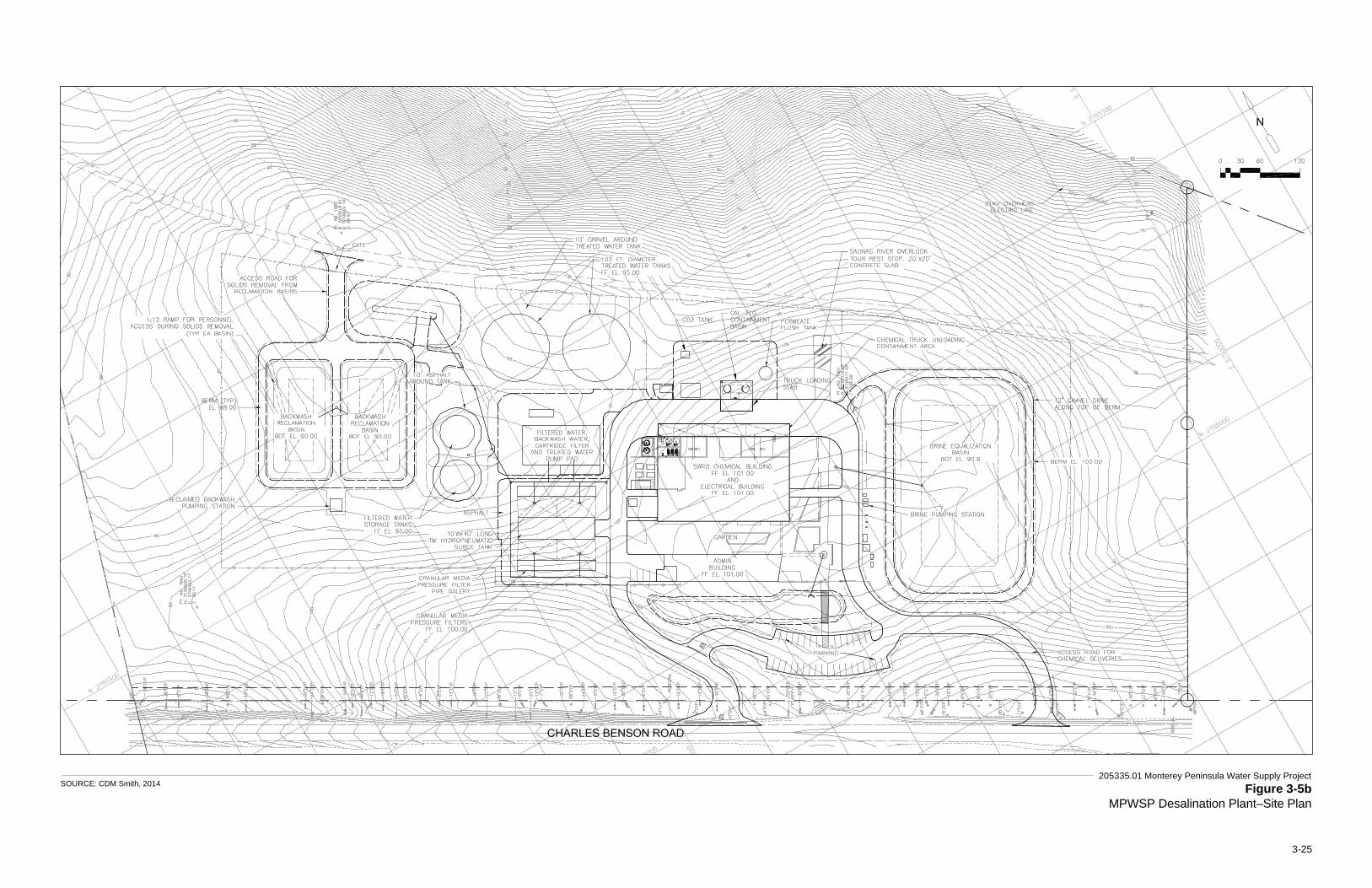
205335.01 Monterey Peninsula Water Supply Project Figure 3-5b
MPWSP Desalination Plant–Site PlanSOURCE: CDM Smith, 2014
3-25
3. Description of the Proposed Project
CalAm Monterey Peninsula Water Supply Project 3-26 ESA / 205335.01 Final EIR/EIS March 2018
This page intentionally left blank
3. Description of the Proposed Project
CalAm Monterey Peninsula Water Supply Project 3-27 ESA / 205335.01 Final EIR/EIS March 2018
A multi-purpose pump station located near the center of the MPWSP Desalination Plant would be built on an outdoor concrete pad with an approximate area of 8,000 square feet. The pump station would include pumping equipment related to pretreatment as well as other processes described later in this section (e.g., treated water and Salinas Valley return water conveyance). Equipment would include seven cartridge filters; four filtered water pumps (two 12 mgd and 350 hp each; and two 6 mgd and 200 hp each); two backwash supply pumps (16 mgd and 150 hp each); four treated water pumps (two 4.8 mgd and 600 hp each; and two 2.4 mgd and 300 hp each); two Salinas Valley return pumps (1.4 mgd and 10 hp each); and associated piping, valves, and instruments.
3.2.2.2 Reverse Osmosis System RO is an ion separation process that uses semipermeable membranes to remove salts and other minerals from saline water. Pretreated source water is forced at very high pressures through RO membranes. Water molecules, which are smaller than salt and many other impurities, are able to pass through the membranes. A portion of the source water passes through the RO membranes to produce “permeate,” or desalinated water; the source water that does not pass through the membranes increases in salt concentration and is discharged as brine, as described in more detail below.
The RO system would be housed in an approximately 30-foot-tall, 30,000-square-foot membrane process building located in the central portion of the MPWSP Desalination Plant site. This building would also house the UV disinfection system (if required) and the cleaning system for the RO membranes (see descriptions below).
The RO process would consist of a first-pass system and a partial (40 to 50 percent) second-pass system. The first-pass RO system would comprise RO modules (six active and one standby), each sized to produce 1.6 mgd of permeate. Variable-speed, low-pressure pumps would pump pretreated source water to variable-speed, high-pressure, first-pass RO feed pumps. The high-pressure RO feed pumps would deliver flow to the first-pass membrane arrays.
Low-pressure, variable-speed pumps would be used to pump the 40 to 50 percent of the first-pass permeate that has a higher concentration of dissolved solids than the rest of the permeate to the second-pass membrane arrays. The second-pass system would reduce the concentrations of these dissolved solids (boron, chloride, and sodium) and would comprise four RO modules (three active and one standby), each sized to produce 1.3 mgd of permeate. The second-pass permeate would then be blended with the bypassed portion of the first-pass permeate to meet required desalinated water quality standards. Approximately 23.6 mgd of pretreated source water would be needed to produce 9.6 mgd of desalinated water.
The RO process would incorporate an energy recovery system that uses pressure-exchange technologies. The use of high-pressure pumps to force saline water through the RO membranes would produce a concentrated brine solution, known as RO concentrate, in a continuous high-pressure stream. Pressure exchangers would be employed to transfer the energy from the high-pressure brine stream to the source water stream to reduce energy demand and operating costs.
3. Description of the Proposed Project
CalAm Monterey Peninsula Water Supply Project 3-28 ESA / 205335.01 Final EIR/EIS March 2018
The accumulation of salts or scaling (from to microbial contamination, turbidity, and other contaminants such as iron and manganese) on the RO membranes causes fouling, which reduces membrane performance. The pretreatment system described above would reduce fouling of the RO membranes, increasing the efficiency of the RO system and extending the useful life of the RO membranes. However, the RO system still would require cleaning two to three times per year. The RO cleaning system would be housed in the same building as the RO system and would include chemical storage, chemical feedlines, and a collection tank. System operators would clean the RO membranes by circulating a cleaning solution, made of strong bases or acids, through the membranes and then flushing the membranes with clean water to remove the spent cleaning solution and waste effluent from the RO system. The spent cleaning solution and waste effluent would be discharged into a collection tank, chemically neutralized, and discharged to the sanitary sewer system at the eastern portion of the MPWSP Desalination Plant site.
CalAm would install a 750-kilowatt (kW) (1,000 hp) emergency diesel fuel-powered generator and a 2,000-gallon, double-walled, aboveground diesel storage tank next to the process building. The generator would provide backup power for critical desalination plant facilities (e.g., lights, electrical controls, and high-service pumps to empty the clearwells) during power outages. Electrical power service and facilities for normal (non-emergency) operations are described below in Section 3.2.5.
3.2.2.3 Post-treatment System After leaving the RO system, the desalinated water would pass through a post-treatment system to make the water more compatible with the other water supply sources in the CalAm system and provide adequate disinfection prior to distribution to customers. Facility operators would use metering pumps and chemical feedlines to dose the post-treatment chemicals through the proper injection points along the post-treatment system. Post-treatment facilities would include chemical feedlines and injection systems for lime and carbon dioxide. Carbon dioxide would be added to adjust alkalinity; lime would be added to adjust calcium hardness; sodium hydroxide would be used to adjust pH; and sodium hypochlorite would be added for disinfection. In addition, an ultraviolet disinfection system may be required to comply with pathogen removal/inactivation standards established by the Surface Water Treatment Rule and Long Term 2 Enhanced Surface Water Treatment Rule. If required, the ultraviolet disinfection system would comprise three reactors, two active and one standby, housed in the membrane process building. The final design of post-treatment facilities would be based on the water quality data collected during operation of the test slant well and pilot program and the results of a geochemical mixing study.8 Any adjustments made to the post-treatment system during final design of the MPWSP Desalination Plant within the 25-acre development area would not affect any of the analyses or conclusions in this EIR/EIS. All treatment chemicals would be transported, stored and used in accordance with regulatory requirements.
8 The geochemical mixing study will identify water quality parameters for the desalinated product water to ensure
that any desalinated product water injected into underground storage via the ASR system would not adversely affect groundwater quality in the Seaside Groundwater Basin. Refer to Impact 4.4-4 in Section 4.4, Groundwater Resources, for additional discussion of the geochemical mixing study.
3. Description of the Proposed Project
CalAm Monterey Peninsula Water Supply Project 3-29 ESA / 205335.01 Final EIR/EIS March 2018
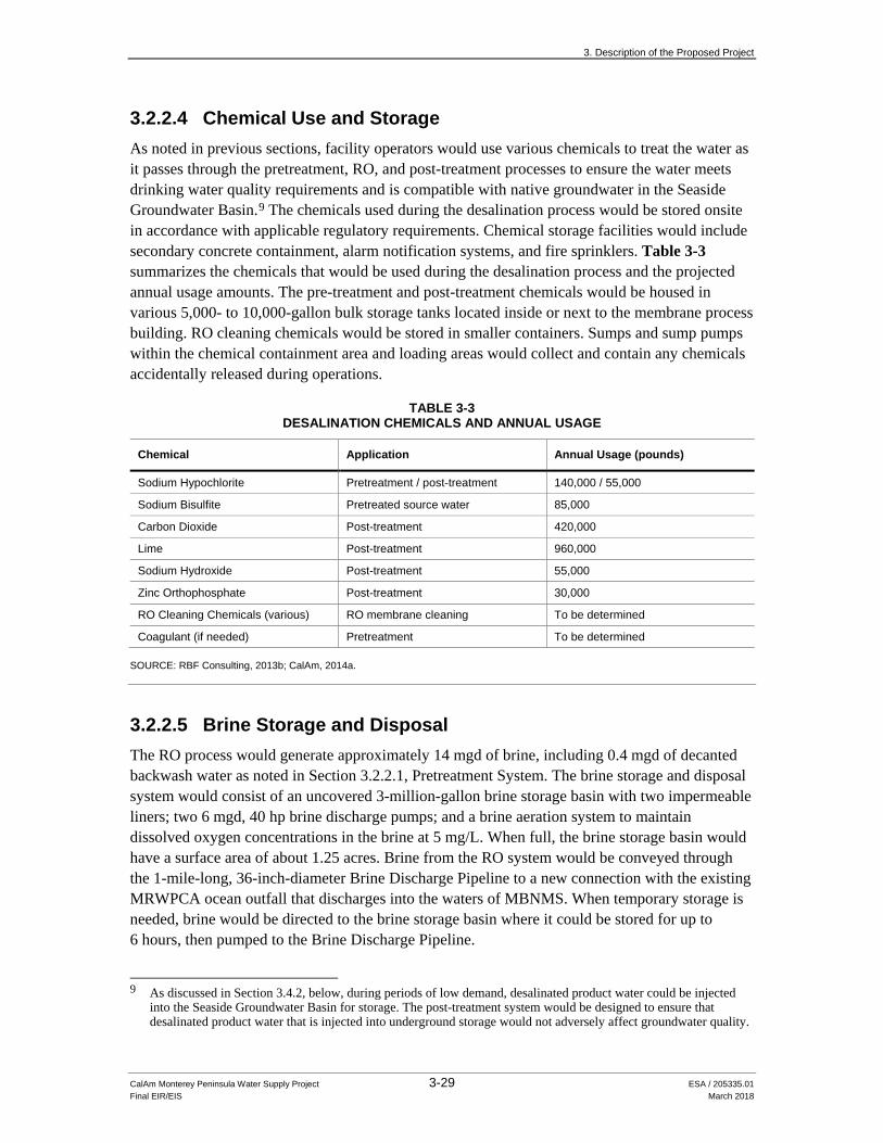
3.2.2.4 Chemical Use and Storage As noted in previous sections, facility operators would use various chemicals to treat the water as it passes through the pretreatment, RO, and post-treatment processes to ensure the water meets drinking water quality requirements and is compatible with native groundwater in the Seaside Groundwater Basin.9 The chemicals used during the desalination process would be stored onsite in accordance with applicable regulatory requirements. Chemical storage facilities would include secondary concrete containment, alarm notification systems, and fire sprinklers. Table 3-3 summarizes the chemicals that would be used during the desalination process and the projected annual usage amounts. The pre-treatment and post-treatment chemicals would be housed in various 5,000- to 10,000-gallon bulk storage tanks located inside or next to the membrane process building. RO cleaning chemicals would be stored in smaller containers. Sumps and sump pumps within the chemical containment area and loading areas would collect and contain any chemicals accidentally released during operations.
TABLE 3-3 DESALINATION CHEMICALS AND ANNUAL USAGE
Chemical Application Annual Usage (pounds)
Sodium Hypochlorite Pretreatment / post-treatment 140,000 / 55,000 Sodium Bisulfite Pretreated source water 85,000 Carbon Dioxide Post-treatment 420,000 Lime Post-treatment 960,000 Sodium Hydroxide Post-treatment 55,000 Zinc Orthophosphate Post-treatment 30,000 RO Cleaning Chemicals (various) RO membrane cleaning To be determined Coagulant (if needed) Pretreatment To be determined
SOURCE: RBF Consulting, 2013b; CalAm, 2014a.
3.2.2.5 Brine Storage and Disposal The RO process would generate approximately 14 mgd of brine, including 0.4 mgd of decanted backwash water as noted in Section 3.2.2.1, Pretreatment System. The brine storage and disposal system would consist of an uncovered 3-million-gallon brine storage basin with two impermeable liners; two 6 mgd, 40 hp brine discharge pumps; and a brine aeration system to maintain dissolved oxygen concentrations in the brine at 5 mg/L. When full, the brine storage basin would have a surface area of about 1.25 acres. Brine from the RO system would be conveyed through the 1-mile-long, 36-inch-diameter Brine Discharge Pipeline to a new connection with the existing MRWPCA ocean outfall that discharges into the waters of MBNMS. When temporary storage is needed, brine would be directed to the brine storage basin where it could be stored for up to 6 hours, then pumped to the Brine Discharge Pipeline.
9 As discussed in Section 3.4.2, below, during periods of low demand, desalinated product water could be injected
into the Seaside Groundwater Basin for storage. The post-treatment system would be designed to ensure that desalinated product water that is injected into underground storage would not adversely affect groundwater quality.
3. Description of the Proposed Project
CalAm Monterey Peninsula Water Supply Project 3-30 ESA / 205335.01 Final EIR/EIS March 2018
During some times of the year, brine would be mixed with varying volumes of treated wastewater from the MRWPCA Regional Wastewater Treatment Plant before being discharged through the ocean outfall. During the irrigation season, April through October, the treated wastewater is diverted to the Salinas Valley Reclamation Project’s tertiary treatment facility for additional advanced treatment and then used to irrigate crops as part of the Castroville Seawater Intrusion Project (CSIP). During this time period, as long as MRWPCA treated wastewater flows are equal to or less than the CSIP demand for irrigation water, the project’s brine stream would be discharged to Monterey Bay without dilution. During the non-irrigation season, November through March, when the CSIP is not operating, the brine stream would at all times be mixed with treated wastewater from the MRWPCA Regional Wastewater Treatment Plant before being discharged to the ocean.
Proper disposal of waste streams requires that the different type of flows be thoroughly mixed prior to discharge to the outfall to prevent stratification in the outfall and to optimize the mixing of the discharge with ocean water. In addition to brine generated by the MPWSP Desalination Plant, the proposed Brine Mixing Box would accept secondary effluent from the MRWPCA Regional Wastewater Treatment Plant, and trucked brine waste collected from individual water softeners and private desalination facilities. The proposed Brine Mixing Box and appurtenances would be located at the southern terminus of the proposed Brine Discharge Pipeline, in a currently undeveloped portion of the MRWPCA property, approximately 0.5 acre in size as shown on Figure 3-5a. The principal components include a diversion structure, piping between the diversion structure and the brine mixing basins, four below-grade mixing basins with mechanical mixers, a laboratory and control building, and a flow meter to measure the total mixed flow returned from the mixing basins to the diversion structure and outfall. Proposed ancillary facilities include a flow bypass system to carry wastewater flows in the outfall during construction of the diversion structure, and to enable future maintenance, a trucked brine station and access road, sampling pumps, a flow bypass system for the brine waste streams in the event the diversion structure is out of service for maintenance, and a fresh water pipeline and appurtenant facilities. The only aboveground components include the laboratory and control building, and a new 22-foot-wide access road (MRWPCA, 2017). A range of possible mixtures of brine and treated wastewater is described in Section 4.3, Surface Water Hydrology and Water Quality.
The existing 2.1-mile-long MRWPCA outfall pipeline ends with a 1,100-foot-long, underwater diffuser that rests on ballast rock. The ports are approximately 6 inches above the ballast rock and nominally 54 inches above the seafloor, although this varies. For the dilution calculations, they are assumed to be 4 feet above the seafloor at approximately 90 to 110 feet below sea level. The diffuser is equipped with 172 ports (129 open and 43 closed), each 2 inches in diameter and spaced 8 feet apart.
3.2.2.6 Administrative Building A 4,000- to 6,000-square-foot single-story administrative building at the MPWSP Desalination Plant site would house visitor reception, offices, restrooms, locker rooms, break rooms, conference rooms, a control room, a laboratory, an equipment storage and maintenance area, and
3. Description of the Proposed Project
CalAm Monterey Peninsula Water Supply Project 3-31 ESA / 205335.01 Final EIR/EIS March 2018
monitoring and control systems for the RO system, post-treatment system, chemical feed systems, and related facilities.
3.2.3 Desalinated Water Conveyance Desalinated product water from the MPWSP Desalination Plant would flow south through a series of proposed pipelines (i.e., the new Desalinated Water Pipeline and new Transmission Main), including surface equipment such as valves and blowoffs, to existing CalAm water infrastructure, as described in Sections 3.2.3.3 through 3.4.3.9.
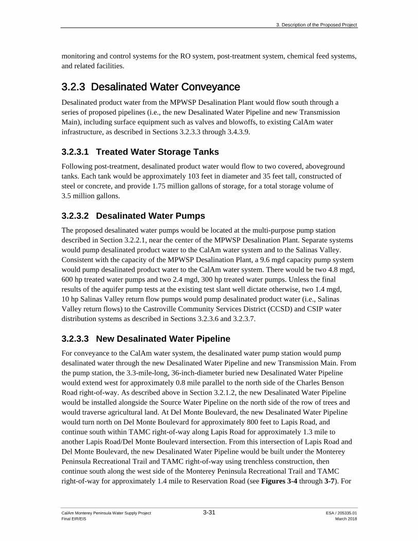
3.2.3.1 Treated Water Storage Tanks Following post-treatment, desalinated product water would flow to two covered, aboveground tanks. Each tank would be approximately 103 feet in diameter and 35 feet tall, constructed of steel or concrete, and provide 1.75 million gallons of storage, for a total storage volume of 3.5 million gallons.
3.2.3.2 Desalinated Water Pumps The proposed desalinated water pumps would be located at the multi-purpose pump station described in Section 3.2.2.1, near the center of the MPWSP Desalination Plant. Separate systems would pump desalinated product water to the CalAm water system and to the Salinas Valley. Consistent with the capacity of the MPWSP Desalination Plant, a 9.6 mgd capacity pump system would pump desalinated product water to the CalAm water system. There would be two 4.8 mgd, 600 hp treated water pumps and two 2.4 mgd, 300 hp treated water pumps. Unless the final results of the aquifer pump tests at the existing test slant well dictate otherwise, two 1.4 mgd, 10 hp Salinas Valley return flow pumps would pump desalinated product water (i.e., Salinas Valley return flows) to the Castroville Community Services District (CCSD) and CSIP water distribution systems as described in Sections 3.2.3.6 and 3.2.3.7.
3.2.3.3 New Desalinated Water Pipeline For conveyance to the CalAm water system, the desalinated water pump station would pump desalinated water through the new Desalinated Water Pipeline and new Transmission Main. From the pump station, the 3.3-mile-long, 36-inch-diameter buried new Desalinated Water Pipeline would extend west for approximately 0.8 mile parallel to the north side of the Charles Benson Road right-of-way. As described above in Section 3.2.1.2, the new Desalinated Water Pipeline would be installed alongside the Source Water Pipeline on the north side of the row of trees and would traverse agricultural land. At Del Monte Boulevard, the new Desalinated Water Pipeline would turn north on Del Monte Boulevard for approximately 800 feet to Lapis Road, and continue south within TAMC right-of-way along Lapis Road for approximately 1.3 mile to another Lapis Road/Del Monte Boulevard intersection. From this intersection of Lapis Road and Del Monte Boulevard, the new Desalinated Water Pipeline would be built under the Monterey Peninsula Recreational Trail and TAMC right-of-way using trenchless construction, then continue south along the west side of the Monterey Peninsula Recreational Trail and TAMC right-of-way for approximately 1.4 mile to Reservation Road (see Figures 3-4 through 3-7). For
3. Description of the Proposed Project
CalAm Monterey Peninsula Water Supply Project 3-32 ESA / 205335.01 Final EIR/EIS March 2018
the purposes of this EIR/EIS, south of Reservation Road this pipeline is referred to as the new Transmission Main (see Section 3.2.3.4).
New Desalinated Water Pipeline – Optional Alignment Similar to the optional alignment for the Source Water Pipeline (see Section 3.2.1.2), the optional alignment for the new Desalinated Water Pipeline would be identical to the alignment described in the paragraph above, except that the 0.8-mile-long segment along Charles Benson Road would be installed within the Charles Benson Road paved right-of-way (as opposed to north of and outside of the right-of-way, along private agricultural lands) (see Figure 3-4). Construction activities within Charles Benson Road would be limited to after hours/nighttime construction, to avoid conflicts with the operations of the Waste Management District.
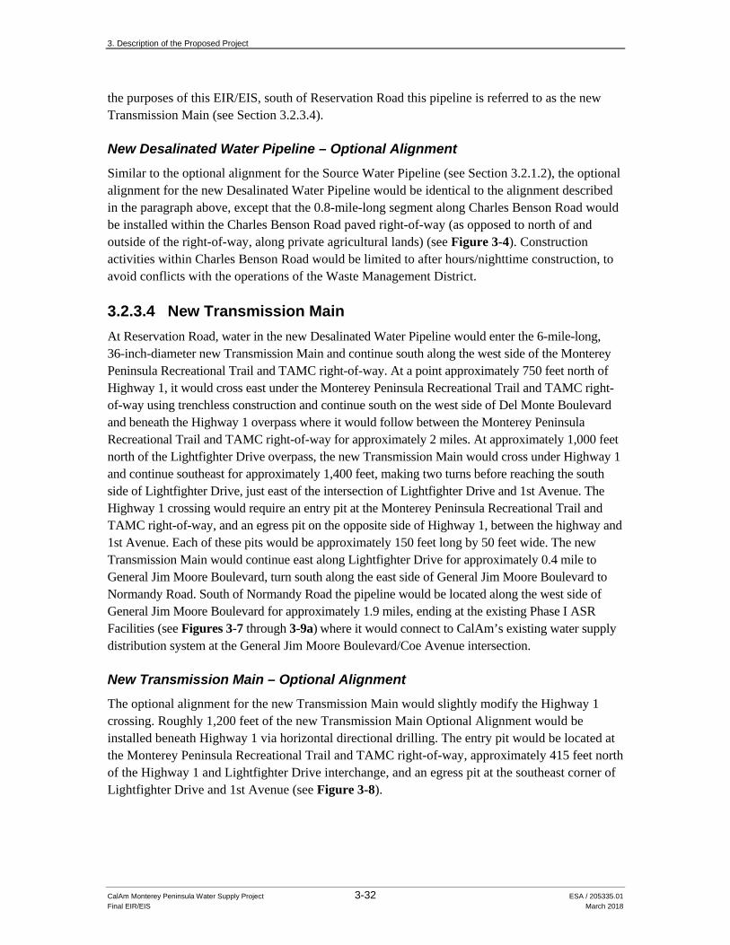
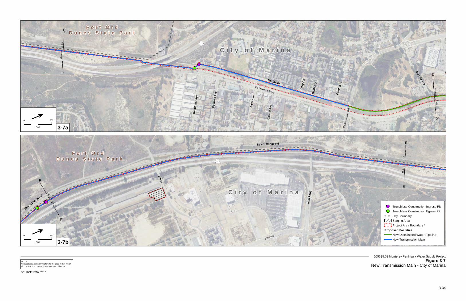
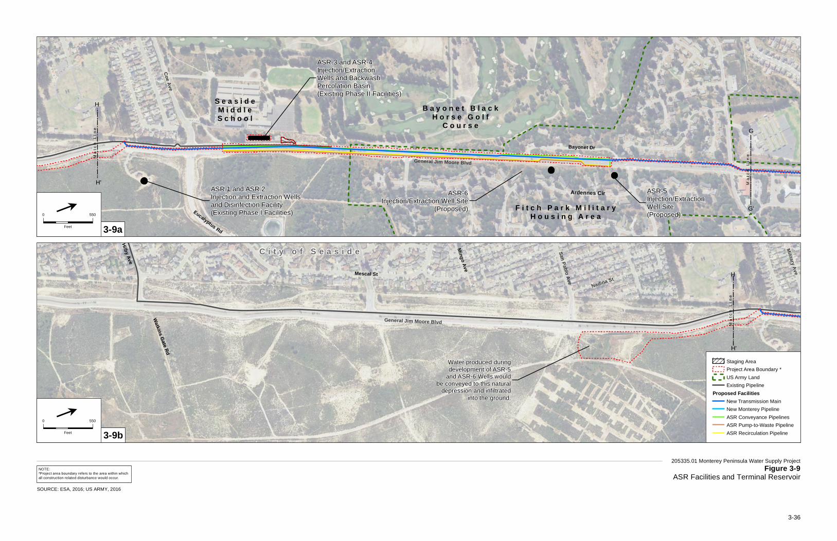
3.2.3.4 New Transmission Main At Reservation Road, water in the new Desalinated Water Pipeline would enter the 6-mile-long, 36-inch-diameter new Transmission Main and continue south along the west side of the Monterey Peninsula Recreational Trail and TAMC right-of-way. At a point approximately 750 feet north of Highway 1, it would cross east under the Monterey Peninsula Recreational Trail and TAMC right-of-way using trenchless construction and continue south on the west side of Del Monte Boulevard and beneath the Highway 1 overpass where it would follow between the Monterey Peninsula Recreational Trail and TAMC right-of-way for approximately 2 miles. At approximately 1,000 feet north of the Lightfighter Drive overpass, the new Transmission Main would cross under Highway 1 and continue southeast for approximately 1,400 feet, making two turns before reaching the south side of Lightfighter Drive, just east of the intersection of Lightfighter Drive and 1st Avenue. The Highway 1 crossing would require an entry pit at the Monterey Peninsula Recreational Trail and TAMC right-of-way, and an egress pit on the opposite side of Highway 1, between the highway and 1st Avenue. Each of these pits would be approximately 150 feet long by 50 feet wide. The new Transmission Main would continue east along Lightfighter Drive for approximately 0.4 mile to General Jim Moore Boulevard, turn south along the east side of General Jim Moore Boulevard to Normandy Road. South of Normandy Road the pipeline would be located along the west side of General Jim Moore Boulevard for approximately 1.9 miles, ending at the existing Phase I ASR Facilities (see Figures 3-7 through 3-9a) where it would connect to CalAm’s existing water supply distribution system at the General Jim Moore Boulevard/Coe Avenue intersection.
New Transmission Main – Optional Alignment The optional alignment for the new Transmission Main would slightly modify the Highway 1 crossing. Roughly 1,200 feet of the new Transmission Main Optional Alignment would be installed beneath Highway 1 via horizontal directional drilling. The entry pit would be located at the Monterey Peninsula Recreational Trail and TAMC right-of-way, approximately 415 feet north of the Highway 1 and Lightfighter Drive interchange, and an egress pit at the southeast corner of Lightfighter Drive and 1st Avenue (see Figure 3-8).

Ci t y o f
Ma r i n a
CEM
EX
Settling Ponds
M o n t e r e y P e n i n s u l a R e c r e a t i o n a l T r a i l
Del Monte Blvd
C i t y o f M a r i n a U n i n c o r p o r a t e dM o n t e r e y C o u n t y
UV1
Del Monte Blvd
Lapis Rd
Marina Dr
Mich
ael D
r
Paul Davis Dr
Cosk
y Dr
Healy
AveLil
lian P
l
Sean
CtBegonia Cir
Linde
Cir
Harbe
n Cir
Fitzgerald Cir
Mich
elle C
t
Legio
n Way
Mccu
lloch
Cir
Sells
Ct
Michael Dr
Beach Rd
Ma
tch
Lin
e
Ma
t ch
Li n
e
205335.01 Monterey Peninsula Water Supply ProjectFigure 3-6
New Desalinated Water PipelineSOURCE: ESA, 2016
Trenchless Construction Ingress PitTrenchless Construction Egress PitCity BoundaryStaging AreaProject Area Boundary *
Proposed FacilitiesNew Desalinated Water PipelineSource Water Pipeline
0 550
Feet
l
NOTE:*Project area boundary refers to the area within whichall construction related disturbance would occur.
A'
A
D'
D
3-33
Carm
el Av
e
Del Monte Blvd
Rese
rvatio
n Rd
C i t y o f M a r i n a
F o r t O r dD u n e s S t a t e P a r k
Begonia Cir
Fitzgerald Cir
Marina Dr
Palm
Ave
Reind
ollar
Ave
Hillc
rest A
ve
Padd
on Pl
Seaside Ave
Cypr
ess A
ve
CarswellSt
Terry
Cir
Debb
ie Dr
UV1
Ma
t ch
Li n
e
Ma
t ch
Li n
e
205335.01 Monterey Peninsula Water Supply ProjectFigure 3-7
New Transmission Main - City of Marina
8th St
Beach Range Rd
2nd Ave2nd St
UV1
2nd Ave
Beach Range Rd C i t y o f M a r i n a
F o r t O r d D u n e s S t a t e P a r k
Imjin
Pkwy
2nd Ave
CarswellSt
Ma
t ch
Li n
e
Ma
t ch
Li n
e
3-7a
3-7b
0 550
Feet
l
0 550
Feet
l
NOTE:*Project area boundary refers to the area within whichall construction related disturbance would occur.
D'
DE'
E
E'
E
F'
F
Trenchless Construction Ingress PitTrenchless Construction Egress PitCity BoundaryStaging AreaProject Area Boundary *
Proposed FacilitiesNew Desalinated Water PipelineNew Transmission Main
SOURCE: ESA, 2016
3-34

New Transmission MainOptional Alignment
CalState UniversityMonterey Bay Athletic Fields
2nd St
2nd Ave
Gigli
ng R
d
Monterey Rd
6th Army Ave
6th Division Cir
Normandy Rd
UV1
General Jim Moore Blvd
Light Fighter Dr
Aachen Rd
C i t y o fM a r i n a
C i t y o fS e a s i d e
Ma
t ch
Li n
e
Ma
t ch
Li n
e
205335.01 Monterey Peninsula Water Supply ProjectFigure 3-8
New Transmission Main - Light Fighter Driveto General Jim Moore Boulevard
NOTE:*Project area boundary refers to the area within whichall construction related disturbance would occur.
F'
F
G'
G
SOURCE: ESA, 2016; US ARMY, 2016
Trenchless Construction Ingress PitTrenchless Construction Egress PitCity BoundaryUS Army LandStaging AreaProject Area Boundary *
Proposed FacilitiesNew Transmission Main New Transmission Main Optional Alignment
0 550
Feet
l
3-35
ASR-5Injection/Extraction Well Site(Proposed)
ASR-6Injection/Extraction Well Site
(Proposed)
ASR 1 and ASR 2Injection and Extraction Wellsand Disinfection Facility(Existing Phase I Facilities)
S e a s i d eM i d d l eS c h o o l
B a y o n e t B l a c kH o r s e G o l f
C o u r s e
F i t c h P a r k M i l i t a r yH o u s i n g A r e a
ASR-3 and ASR-4Injection/ExtractionWells and BackwashPercolation Basin(Existing Phase II Facilities)
Ardennes Cir
Elbe R
d
Eucalyptus Rd
Monterey Rd
Bayonet Dr
General Jim Moore Blvd
Coe Ave
Ma
tch
Lin
eMa
tch
Lin
e
205335.01 Monterey Peninsula Water Supply ProjectFigure 3-9
ASR Facilities and Terminal ReservoirNOTE:*Project area boundary refers to the area within whichall construction related disturbance would occur.
C i t y o f S e a s i d e Military AveMescal St
Mingo Ave
General Jim Moore Blvd
San Pablo Ave
Broadway Ave
Nadina StGeneral Jim Moore Blvd
Hilby Ave
Watkins Gate Rd
Water produced duringdevelopment of ASR-5
and ASR-6 Wells wouldbe conveyed to this natural
depression and infiltratedinto the ground.
Ma
tch
Lin
e
3-9a
3-9b
0 550
Feet
l
0 550
Feet
l
G'
G
H'
H
H
SOURCE: ESA, 2016; US ARMY, 2016
Staging AreaProject Area Boundary *US Army LandExisting Pipeline
Proposed FacilitiesNew Transmission MainNew Monterey PipelineASR Conveyance PipelinesASR Pump-to-Waste PipelineASR Recirculation Pipeline
H'
3-36

3. Description of the Proposed Project
CalAm Monterey Peninsula Water Supply Project 3-37 ESA / 205335.01 Final EIR/EIS March 2018
3.2.3.5 Carmel Valley Pump Station The Valley Greens pressure zone, in Carmel Valley south of the Segunda Reservoir, does not have sufficient hydraulic head to fill the existing Segunda Reservoir, which is located at the southern end of the existing Segunda Pipeline. The proposed Carmel Valley Pump Station, with a pumping capacity of 3 mgd (2,100 gpm), would provide the additional pressure needed to fill Segunda Reservoir. The pump station would be enclosed in a 500-square-foot, single-story building on a site located approximately 240 feet south of Carmel Valley Road near the intersection of Rancho San Carlos Road (see Figure 3-10c). A 50 kW (68 hp) portable diesel-fuel powered generator would be stored onsite for use in the event of a power outage. A separate 100-square-foot electrical control building would be constructed outside of the pump station building.
3.2.3.6 Castroville Pipeline The 4.5-mile-long, 12-inch-diameter Castroville Pipeline would convey desalinated Salinas Valley return water from the MPWSP Desalination Plant to the CSIP distribution system and the CCSD Well #3. As described in Chapter 2, Water Demand, Supplies and Water Rights, the portion of the water drawn from the subsurface slant wells that is determined to be groundwater originating from the Salinas Valley Groundwater Basin, would be delivered to CCSD as desalinated water in lieu of CCSD pumping an equivalent amount of groundwater. Under the proposed project, the first 800 afy would go to the CCSD and the remaining water would go to the CSIP.
From the MPWSP Desalination Plant, the Castroville Pipeline would head west along the north side (outside of the paved roadway, through agricultural land) of Charles Benson Road to Del Monte Boulevard, at which point the pipeline would head north. The pipeline would be installed along Del Monte Boulevard to Lapis Road and then along the west side of Lapis Road within the TAMC right-of-way and along Monte Road, and would cross over the Salinas River at Monte Road by being attached to the underside of the Monte Road Bridge. On the north side of the Salinas River bridge, the pipeline would continue northeast along the TAMC right-of-way and Monte Road to Nashua Road. A new pipe connection to the CSIP distribution system would be built at the northern end of Monte Road, where it meets Nashua Road. The Castroville Pipeline would continue north along a dirt agricultural road and the Union Pacific Railroad, crossing under Tembladero Slough to Highway 183 (Salinas Road). From Highway 183, the pipeline would continue north between Del Monte Avenue and Union Pacific Railroad, turn west across Del Monte Avenue and connect to CCSD Well #3 at the north corner of Del Monte Avenue and Merritt Street (see Figures 3-4, 3-5, 3-11, and 3-12).
Castroville Pipeline – Optional Alignment 1 Optional Alignment 1 would provide an alternate pipeline route from the intersection of Monte Road and Nashua Road to CCSD Well #3. From the intersection of Monte Road and Nashua Road, Optional Alignment 1 would turn northwest along Nashua Road to the Monterey Peninsula Recreational Trail. It would continue northeast along the Monterey Peninsula Recreational Trail on the east side of Highway 1 for approximately 1.5 mile to Merrit Way and continue southeast on Merritt Street for 0.5 mile to CCSD Well #3 (see Figures 3-11b, 3-12, and 3-13).
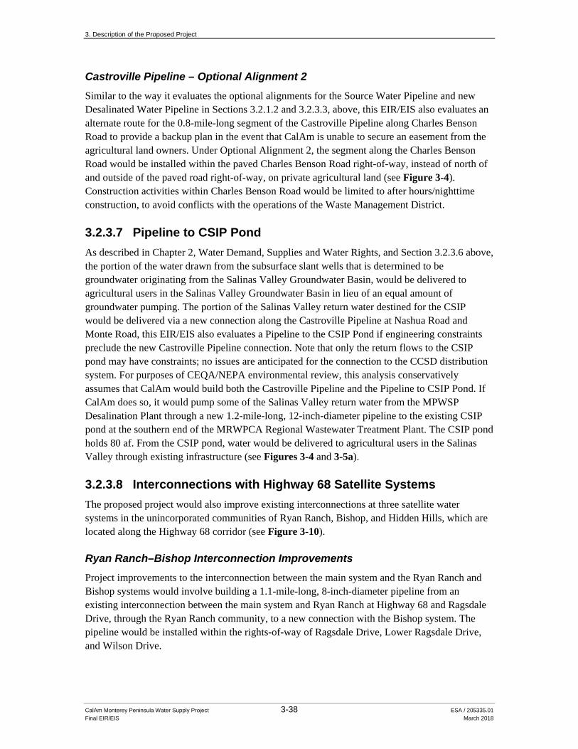
3. Description of the Proposed Project
CalAm Monterey Peninsula Water Supply Project 3-38 ESA / 205335.01 Final EIR/EIS March 2018
Castroville Pipeline – Optional Alignment 2 Similar to the way it evaluates the optional alignments for the Source Water Pipeline and new Desalinated Water Pipeline in Sections 3.2.1.2 and 3.2.3.3, above, this EIR/EIS also evaluates an alternate route for the 0.8-mile-long segment of the Castroville Pipeline along Charles Benson Road to provide a backup plan in the event that CalAm is unable to secure an easement from the agricultural land owners. Under Optional Alignment 2, the segment along the Charles Benson Road would be installed within the paved Charles Benson Road right-of-way, instead of north of and outside of the paved road right-of-way, on private agricultural land (see Figure 3-4). Construction activities within Charles Benson Road would be limited to after hours/nighttime construction, to avoid conflicts with the operations of the Waste Management District.
3.2.3.7 Pipeline to CSIP Pond As described in Chapter 2, Water Demand, Supplies and Water Rights, and Section 3.2.3.6 above, the portion of the water drawn from the subsurface slant wells that is determined to be groundwater originating from the Salinas Valley Groundwater Basin, would be delivered to agricultural users in the Salinas Valley Groundwater Basin in lieu of an equal amount of groundwater pumping. The portion of the Salinas Valley return water destined for the CSIP would be delivered via a new connection along the Castroville Pipeline at Nashua Road and Monte Road, this EIR/EIS also evaluates a Pipeline to the CSIP Pond if engineering constraints preclude the new Castroville Pipeline connection. Note that only the return flows to the CSIP pond may have constraints; no issues are anticipated for the connection to the CCSD distribution system. For purposes of CEQA/NEPA environmental review, this analysis conservatively assumes that CalAm would build both the Castroville Pipeline and the Pipeline to CSIP Pond. If CalAm does so, it would pump some of the Salinas Valley return water from the MPWSP Desalination Plant through a new 1.2-mile-long, 12-inch-diameter pipeline to the existing CSIP pond at the southern end of the MRWPCA Regional Wastewater Treatment Plant. The CSIP pond holds 80 af. From the CSIP pond, water would be delivered to agricultural users in the Salinas Valley through existing infrastructure (see Figures 3-4 and 3-5a).
3.2.3.8 Interconnections with Highway 68 Satellite Systems The proposed project would also improve existing interconnections at three satellite water systems in the unincorporated communities of Ryan Ranch, Bishop, and Hidden Hills, which are located along the Highway 68 corridor (see Figure 3-10).
Ryan Ranch–Bishop Interconnection Improvements Project improvements to the interconnection between the main system and the Ryan Ranch and Bishop systems would involve building a 1.1-mile-long, 8-inch-diameter pipeline from an existing interconnection between the main system and Ryan Ranch at Highway 68 and Ragsdale Drive, through the Ryan Ranch community, to a new connection with the Bishop system. The pipeline would be installed within the rights-of-way of Ragsdale Drive, Lower Ragsdale Drive, and Wilson Drive.
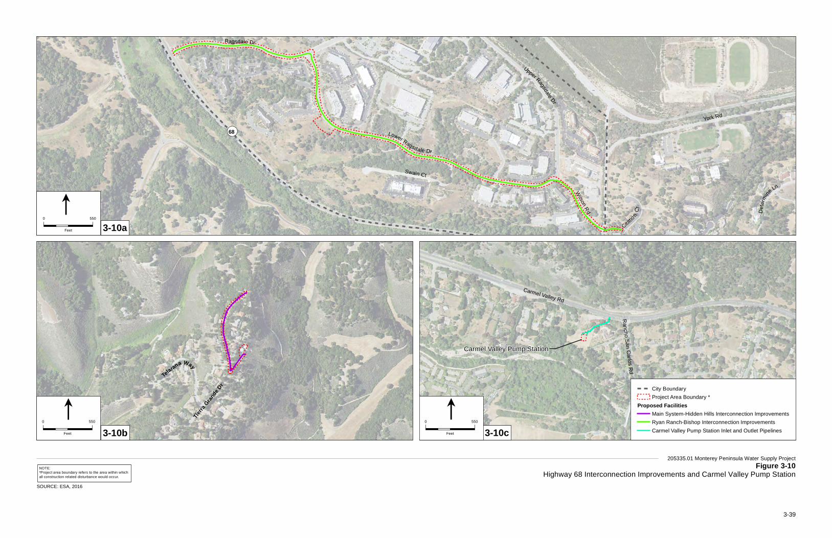
¬«68 York Rd
Lower Ragsdale Dr
Ragsdale Dr
Swain Ct
Upper RagsdaleDr
Wilson
Rd D
eter
mine
Ln
Citatio
nC
t
205335.01 Monterey Peninsula Water Supply ProjectFigure 3-10
Highway 68 Interconnection Improvements and Carmel Valley Pump Station
Tierra
Grande
Dr
Telarana Way
3-10a
3-10b
0 550
Feet
l
0 550
Feet
l
NOTE:*Project area boundary refers to the area within whichall construction related disturbance would occur.
SOURCE: ESA, 2016
Carmel Valley Rd
Rancho San C
arlos Rd
3-10c0 550
Feet
lCity BoundaryProject Area Boundary *
Proposed FacilitiesMain System-Hidden Hills Interconnection ImprovementsRyan Ranch-Bishop Interconnection ImprovementsCarmel Valley Pump Station Inlet and Outlet Pipelines
Carmel Valley Pump Station
3-39
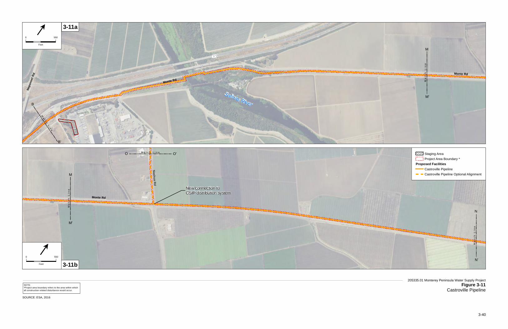
Salinas River
Monte Rd
Nepo
nset
Rd
UV1
Monte Rd
Artichoke Rd
UV1
Ma
t c h L
i ne
Ma
tch
Li n
e
205335.01 Monterey Peninsula Water Supply ProjectFigure 3-11
Castroville Pipeline
New connection toCSIP distribution system
Monte Rd
Artichoke Rd
UV1
Nashua Rd
Ma
t ch
Li n
e
M a t c h L i n e
Ma
tch
Lin
e
3-11a
3-11b
0 550
Feet
l
0 550
Feet
l
NOTE:*Project area boundary refers to the area within whichall construction related disturbance would occur.
M'
M
B'
B
N'
N
M'
M
Staging AreaProject Area Boundary *
Proposed FacilitiesCastroville PipelineCastroville Pipeline Optional Alignment
SOURCE: ESA, 2016
O O'
3-40

Connection to Castroville CommunityServices District (CCSD) distribution system
UV156
§̈¦183
Oak St
Del M
ont e
Ave
Merritt Way
C a s t r o v i l l e
Ma
t c h L
i ne
Ma
t c h L
i ne
205335.01 Monterey Peninsula Water Supply ProjectFigure 3-12
Castroville Pipeline - Connection to CCSD Distribution System
Trenchless Construction Ingress PitTrenchless Construction Egress PitCity BoundaryProject Area Boundary *
Proposed FacilitiesCastroville PipelineCastroville Pipeline Optional Alignment
N'
N
0 550
Feet
l
NOTE:*Project area boundary refers to the area within whichall construction related disturbance would occur.
SOURCE: ESA, 2016
P'
P
3-41

3. Description of the Proposed Project
CalAm Monterey Peninsula Water Supply Project 3-42 ESA / 205335.01 Final EIR/EIS March 2018
This page intentionally left blank
UV1
UV156
Artichoke Rd
UV1
Nashua Rd
Oak St
Ma
t ch
Li n
e
M a t c h L i n e
205335.01 Monterey Peninsula Water Supply Project Figure 3-13
Castroville Pipeline Optional Alignment
SOURCE: ESA, 2016
Proposed FacilitiesCastroville Pipeline Optional Alignment
0 550
Feet
l
P'
P
O'O
3-43

3. Description of the Proposed Project
CalAm Monterey Peninsula Water Supply Project 3-44 ESA / 205335.01 Final EIR/EIS March 2018
This page intentionally left blank
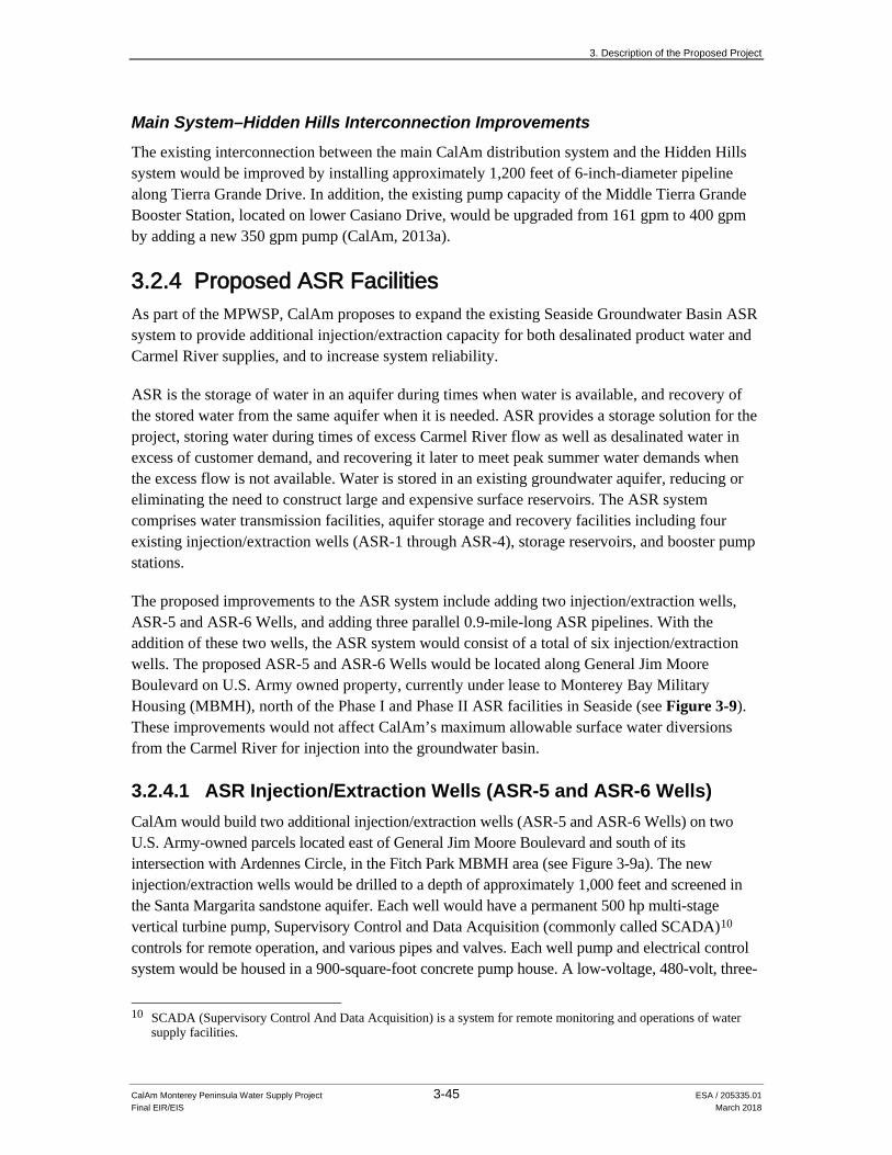
3. Description of the Proposed Project
CalAm Monterey Peninsula Water Supply Project 3-45 ESA / 205335.01 Final EIR/EIS March 2018
Main System–Hidden Hills Interconnection Improvements The existing interconnection between the main CalAm distribution system and the Hidden Hills system would be improved by installing approximately 1,200 feet of 6-inch-diameter pipeline along Tierra Grande Drive. In addition, the existing pump capacity of the Middle Tierra Grande Booster Station, located on lower Casiano Drive, would be upgraded from 161 gpm to 400 gpm by adding a new 350 gpm pump (CalAm, 2013a).
3.2.4 Proposed ASR Facilities As part of the MPWSP, CalAm proposes to expand the existing Seaside Groundwater Basin ASR system to provide additional injection/extraction capacity for both desalinated product water and Carmel River supplies, and to increase system reliability.
ASR is the storage of water in an aquifer during times when water is available, and recovery of the stored water from the same aquifer when it is needed. ASR provides a storage solution for the project, storing water during times of excess Carmel River flow as well as desalinated water in excess of customer demand, and recovering it later to meet peak summer water demands when the excess flow is not available. Water is stored in an existing groundwater aquifer, reducing or eliminating the need to construct large and expensive surface reservoirs. The ASR system comprises water transmission facilities, aquifer storage and recovery facilities including four existing injection/extraction wells (ASR-1 through ASR-4), storage reservoirs, and booster pump stations.
The proposed improvements to the ASR system include adding two injection/extraction wells, ASR-5 and ASR-6 Wells, and adding three parallel 0.9-mile-long ASR pipelines. With the addition of these two wells, the ASR system would consist of a total of six injection/extraction wells. The proposed ASR-5 and ASR-6 Wells would be located along General Jim Moore Boulevard on U.S. Army owned property, currently under lease to Monterey Bay Military Housing (MBMH), north of the Phase I and Phase II ASR facilities in Seaside (see Figure 3-9). These improvements would not affect CalAm’s maximum allowable surface water diversions from the Carmel River for injection into the groundwater basin.
3.2.4.1 ASR Injection/Extraction Wells (ASR-5 and ASR-6 Wells) CalAm would build two additional injection/extraction wells (ASR-5 and ASR-6 Wells) on two U.S. Army-owned parcels located east of General Jim Moore Boulevard and south of its intersection with Ardennes Circle, in the Fitch Park MBMH area (see Figure 3-9a). The new injection/extraction wells would be drilled to a depth of approximately 1,000 feet and screened in the Santa Margarita sandstone aquifer. Each well would have a permanent 500 hp multi-stage vertical turbine pump, Supervisory Control and Data Acquisition (commonly called SCADA)10 controls for remote operation, and various pipes and valves. Each well pump and electrical control system would be housed in a 900-square-foot concrete pump house. A low-voltage, 480-volt, three-
10 SCADA (Supervisory Control And Data Acquisition) is a system for remote monitoring and operations of water
supply facilities.

3. Description of the Proposed Project
CalAm Monterey Peninsula Water Supply Project 3-46 ESA / 205335.01 Final EIR/EIS March 2018
phase electrical transformer would be installed at each well site to power the electrical control system. Pacific Gas & Electric Company (PG&E), the local electrical utility, would own and operate the electrical transformers. Security fencing would encompass an approximately 0.4- and 0.5-acre area around the ASR-5 and ASR-6 Wells, respectively (RBF Consulting, 2010). One 20-foot-wide access driveway would be constructed within currently undeveloped land between General Jim Moore Boulevard and each of these fenced areas, as shown in Figure 3-14.
The existing ASR disinfection system is housed within the chemical/electrical control building at the site of the existing ASR-1 and ASR-2 Wells.11 The existing disinfection system has sufficient capacity to treat ASR product water extracted from all six ASR injection/extraction wells (i.e., the four Phase I and Phase II wells and the two new wells proposed under the MPWSP). The disinfection system consists of a 5,000-gallon bulk sodium hypochlorite storage tank, chemical metering pumps, and chlorine residual analyzer. The disinfection system includes double containment for all chemical storage and dispensing equipment, protective vent-fume neutralizers, safety showers for operations personnel, and a forced-air ventilation system.
The ASR-5 and ASR-6 Wells would have a combined injection capacity of 4.3 mgd (3,000 gpm) and the same combined extraction capacity (approximately 4.3 mgd). The ASR-5 and ASR-6 Wells would operate in conjunction with the existing ASR-1, ASR-2, ASR-3, and ASR-4 Wells. With implementation of the MPWSP, any of the six ASR injection/extraction wells could be used to inject desalinated product water and Carmel River supplies.
Maintenance of the ASR-5 and ASR-6 Wells would involve routine backflushing of the two wells. Backwash effluent containing elevated levels of sediment and turbidity would be conveyed through the proposed ASR Pump-to-Waste Pipeline (see description below) to the existing settling basin for the Phase I facilities at the intersection of General Jim Moore Boulevard and Coe Avenue, and would infiltrate into the ground. As part of ongoing operations of the ASR system, sediment that accumulates in the settling basin is periodically removed and disposed of at an appropriate disposal site to prevent the settling basin from clogging.
3.2.4.2 ASR Pipelines Three parallel 0.9-mile-long, 16-inch-diameter ASR pipelines – the ASR Recirculation Pipeline, the ASR Conveyance Pipeline, and the ASR Pump-to-Waste Pipeline – would extend along General Jim Moore Boulevard between the proposed ASR-5 and ASR-6 Wells at the Fitch Park MBMH area and the intersection of Coe Avenue and General Jim Moore Boulevard. The ASR Recirculation Pipeline would convey water between existing conveyance pipelines and infrastructure at Coe Avenue and General Jim Moore Boulevard to the ASR-5 and ASR-6 Wells for injection. The ASR Conveyance Pipeline would convey water that is extracted from the ASR-5 and ASR-6 Wells to the same facilities at the intersection of Coe Ave and General Jim Moore Boulevard. The ASR Pump-to-Waste Pipeline would convey backflush effluent from the
11 The existing ASR-1 and ASR-2 Wells are also known as Santa Margarita Wells #1 and #2 in other information
sources.
205335.01 Monterey Peninsula Water Supply Project Figure 3-14
Site Plan: ASR-5 Well and ASR-6 WellSOURCE: RBF Consulting
3-47
3. Description of the Proposed Project
CalAm Monterey Peninsula Water Supply Project 3-48 ESA / 205335.01 Final EIR/EIS March 2018
ASR-5 and ASR-6 Wells to the existing settling basin for the ASR-1 and ASR-2 Wells, which is about 2 miles south of the intersection of General Jim Moore Boulevard and Coe Avenue (see Figure 3-9a). Each of the three 16-inch-diameter ASR pipelines would connect to each of the two new ASR wells; the 36-inch diameter Transmission Main would also connect to each of the two new ASR wells with 16-inch diameter connector pipes (see Figure 3-14).
3.2.5 Electrical Power Facilities Although CalAm may eventually use renewable energy sources to power the MPWSP Desalination Plant (see Section 4.18, Energy Conservation, for a description), this EIR/EIS assumes that all electrical power for the proposed facilities would be provided via new connections to the local PG&E grid. New underground and aboveground power lines would be installed at CEMEX for the subsurface slant wells, at the MPWSP Desalination Plant site, the ASR-5 and ASR-6 Well sites, and Carmel Valley Pump Station to connect the new facilities to the existing power grid.
3.3 Construction
3.3.1 Site Preparation and Construction Staging
3.3.1.1 Site Clearing and Preparation Construction workers would clear and prepare the construction work areas in stages as construction progresses. Before construction starts, the contractor would clear and grade portions of the project area, removing vegetation and debris, as necessary, to provide a relatively level surface for the movement of construction equipment. After construction, the contractor would contour the construction work areas to their original profile, and hydroseed or pave the areas, as appropriate.
3.3.1.2 Staging Areas Construction equipment and materials would be stored within the construction work areas to the extent feasible. Construction staging for the subsurface slant wells at CEMEX, the MPWSP Desalination Plant, and the ASR-5 and ASR-6 Wells would be accommodated entirely within the project area boundary shown in Figures 3-3, 3-5, and 3-9a. For construction of all other facilities and pipelines, construction workers would use nine strategically located staging areas in the project area vicinity. The proposed staging areas are sited with the intent of avoiding sensitive riparian areas or critical habitat for protected species. With the exception of the staging areas at Seaside Middle School and the MRWPCA property, the designated staging areas are primarily paved, gravel, or dirt parking lots located in highly disturbed areas. Table 3-4 summarizes the staging area locations and current site conditions. The staging areas are shown as hatched polygons in Figures 3-3 through 3-12.

3. Description of the Proposed Project
CalAm Monterey Peninsula Water Supply Project 3-49 ESA / 205335.01 Final EIR/EIS March 2018
TABLE 3-4 CONSTRUCTION STAGING AREAS
Location Site Description
Monte Road/Neponset Road in unincorporated Monterey County
Paved parking lot (semi-trucks) at Dole Vegetable Processing Plant
MRWPCA Property In open area to the east of the proposed Brine Mixing Box
Beach Road in Marina Paved parking lot at Walmart Highway 1/1st Street in Marina Gated paved parking lot 2nd Avenue, between Lightfighter Drive and Divarty Street, in Seaside
Paved parking lot at the Cal State University at Monterey Bay Athletic Fields
2nd Avenue/Lightfighter Drive in Seaside Paved parking lot West side of General Jim Moore Boulevard, near Gigling Road, in Seaside
Paved parking lot
East side of General Jim Moore Boulevard, near Gigling Road, in Seaside
Paved parking lot
West side of General Jim Moore Boulevard, near Seaside Middle School, in Seaside
Sandy area
Because all of the staging areas are paved, gravel, or dirt, CalAm’s contractors would not need to remove trees or vegetation to use the sites for staging. They would not lay gravel in dirt staging areas. Except for heavy machinery that is operated solely to move lighter-duty machinery in and out of the staging area, and for the use of a front-loaded backhoe to load and unload material onto transportation vehicles for delivery to the construction sites, heavy machinery would not be operated at the staging areas. Only motion-sensored nighttime lighting would be installed at staging areas.
3.3.2 Well Drilling and Development and Related Site Improvements
3.3.2.1 Subsurface Slant Wells Well installation consists of a two-part process: well drilling and well development. Well development occurs after the wells have been drilled, and is the process of optimizing the water quality and flow into the well. Both are described below.
All construction activities associated with the subsurface slant wells would occur several hundred feet inland of the maximum high-tide elevation and in previously disturbed areas. Surface construction activities would occur outside of MBNMS. Slant well construction would take approximately 15 months to complete, and could take place anytime throughout the overall 24-month construction duration for the proposed project. Construction activities associated with installation of the nine additional subsurface slant wells, including staging, materials storage, and stockpiling, would temporarily disturb approximately 9 acres of land (approximately 1 acre of disturbance per slant well) within the project area boundary shown in Figure 3-3a. Construction activities would occur 24 hours per day, 7 days per week, with multiple slant wells being built simultaneously. Construction-related trucks and vehicles would access the slant well site via
3. Description of the Proposed Project
CalAm Monterey Peninsula Water Supply Project 3-50 ESA / 205335.01 Final EIR/EIS March 2018
Del Monte Boulevard, Lapis Road, and existing access roads in the CEMEX active mining area. The construction contractor would use a temporary field office (mobile trailer) in the southern portion of the project area throughout slant well construction activities. The field office and materials receiving and storage would be contained within the 9-acre construction disturbance area.
The proposed slant wells would be built using a dual rotary drilling rig, pipe trailers, portable drilling fluid tanks, Baker tanks (portable holding tanks), haul trucks, flatbed trucks, pumps, and air compressors. The slant wells would be drilled at approximately 14 degrees below horizontal.
Drilling fluids, such as water, bentonite mud, or environmentally inert biodegradable additives, would be used to drill through the first 100 feet or so of the dry dune sands to prevent the sand from locking up the drill bit inside the conductor casing. The bentonite mud used in this initial portion of the borehole would be recirculated into and out of the boring using a mud tank located next to the drill rig. Drill cuttings would be removed from the drilling mud using a shaker table and then the drilling mud would be re-used. Once the drill bit reaches groundwater, the construction contractor would pump out all of the sand-bentonite mud slurry and put it in a storage container for off-site hauling and disposal. The elevation of the groundwater surface will be determined from the existing monitoring wells (MW-1S and MW-3S).
Below the top of the groundwater table, the remaining 900 feet of borehole would be drilled using water already present in the sand and some potable water; no bentonite mud or other additives would be used to drill this portion. The water and sediment mixture generated during the lower portion of slant well drilling and construction would be placed in settling tanks, as necessary, to allow sediment to settle out. The volume of water produced during this drilling phase would be small enough that the construction contractor would dispose of the clarified effluent by percolating it into the ground at the CEMEX retired mining area. Drilling spoils generated during the lower portion of slant well drilling (i.e., not containing bentonite mud or other additives) would be spread within the construction disturbance area and would not require offsite disposal.
The slant wells would be completed using telescoping casing ranging from 22 to 36 inches in diameter and super-duplex 12- to 20-inch diameter stainless steel well screens. A submersible pump would be lowered several hundred feet into each well. To develop the slant wells, each well would be pumped for 2 to 6 weeks during slant well completion and initial well testing. The water pumped from the wells during well development would be discharged to the ocean within the waters of MBNMS via the test slant well discharge pipe and the existing MRWPCA ocean outfall. CalAm would need to obtain permission from the MRWPCA to accept the well development water (a combination of brackish groundwater and seawater) into its outfall during this time, since use of the outfall may be precluded during relocation of the existing beach junction structure (see cumulative Project No. 61 in Table 4.1-2). This well development process would produce a volume of water too great to percolate into the ground at the CEMEX mining area, as compared to the drilling phase described above. Once built, each well would include up to 12-inch-diameter mechanical discharge piping (i.e., flow meter, isolation valve, check valve, pump control valve, air release valve, and pressure gauge). This discharge mechanical piping would be located in a below ground vault (12 feet by 6 feet). The electrical controls would be located in a fiberglass enclosure. The discharge piping would then transition underground via
3. Description of the Proposed Project
CalAm Monterey Peninsula Water Supply Project 3-51 ESA / 205335.01 Final EIR/EIS March 2018
trenching and connect to the buried source water pipeline. The wellheads would be accessible at grade level once completed.
3.3.2.2 ASR Injection/Extraction Wells Construction activities for new ASR injection/extraction wells would include grading, installation and removal of temporary sound walls; well drilling, installation of pipeline connections to the proposed ASR Conveyance Pipelines along General Jim Moore Boulevard, and installation of electrical equipment and pumps. Construction equipment would include drill rigs, water tanks, pipe trucks, flatbed trucks, and several service vehicles. The new ASR injection/extraction wells would be drilled using the reverse rotary drilling method. Bentonite drilling fluids would not be used during well drilling, but non-corrosive, environmentally inert, biodegradable additives might be used to keep the borehole open if necessary. Construction of the ASR-5 and ASR-6 Wells and associated facilities would take approximately 12 months. Most construction activities would extend from 7 a.m. to 7 p.m., 5 days per week, with the exception of 4 weeks of 24-hour construction for each new ASR injection/extraction well during well development and completion (total of 8 weeks of 24-hour construction), until final depth is reached and the borehole is stabilized. This would prevent the borehole from potentially collapsing in on itself, filling the borehole with the surrounding geologic materials, and/or binding up the drill bit and trapping it in the borehole.
Water produced during development of the ASR-5 and ASR-6 Wells at the Fitch Park MBMH housing area would be conveyed to a 1.4-acre natural depression located east of the intersection of San Pablo Avenue and General Jim Moore Boulevard via the pump to waste pipeline and percolated into the ground. The well development water would be disposed of in accordance with Central Coast Regional Water Quality Control Board (RWQCB) Resolution No. R3-2008-0010, General Waiver for Specific Types of Discharges (RWQCB, 2008). Any waste material generated during construction of the proposed ASR facilities that requires off-site disposal would be transported to an approved landfill facility.
3.3.3 Desalination Plant Construction Construction workers would access the MPWSP Desalination Plant site via Charles Benson Road and existing access roads. Construction activities would include cutting, laying, and welding pipelines and pipe connections; pouring concrete footings for foundations, tanks, and other support equipment; building walls and roofs; assembling and installing major desalination process components; installing piping, pumps, storage tanks, and electrical equipment; testing and commissioning facilities; and finish work such as paving, landscaping, and fencing the perimeter of the site. Construction equipment would include excavators, backhoes, graders, pavers, rollers, bulldozers, concrete trucks, flatbed trucks, boom trucks, cranes, forklifts, welding equipment, dump trucks, air compressors, and generators. Pretreatment, RO, and post-treatment facilities would be prefabricated and delivered to the site for installation. Approximately 25 acres of the 46-acre site would be disturbed during construction (see Figure 3-5). No import or export of fill material would be necessary. Construction activities at the desalination plant site are expected to occur over 24 months.

3. Description of the Proposed Project
CalAm Monterey Peninsula Water Supply Project 3-52 ESA / 205335.01 Final EIR/EIS March 2018
3.3.4 Pipeline Installation Approximately 21 miles of pipelines would be installed within the paved roadway or adjacent to roads and the Monterey Peninsula Recreational Trail. Most pipeline segments would be installed using conventional open-trench technology; however, where it is not feasible or desirable to perform open-cut trenching, trenchless methods would be used.
Typical construction equipment for pipeline installation would include flatbed trucks, backhoes, excavators, pipe cutting and welding equipment, haul trucks for spoils transport, trucks for materials delivery, compaction equipment, Baker tanks, pickup trucks, arch welding machines, generators, air compressors, cranes, drill rigs, and skip loaders. Pipeline segments would typically be delivered and installed in 6- to 40-foot-long sections. Soil removed from trenches and pits would be stockpiled and reused, to the extent feasible, or hauled away for offsite disposal. Under typical circumstances, the width of the disturbance corridor for pipeline construction would vary from 50 to 100 feet, depending on the size of the pipe being installed. Trenchless technologies could require wider corridors at entry and exit pits. Multiple pipelines would be built simultaneously. Although most pipeline construction would occur over a 15-month period, pipeline construction could occur any time throughout the entire 24-month construction period. As shown in Table 3-5, the construction durations for most individual pipelines would be much shorter than 15 months. Pipeline installation would be sequenced to minimize land use disturbance and traffic disruption to the extent possible.
3.3.4.1 Open-Trench Construction For pipeline segments to be installed using open-trench methods, the construction sequence would typically include:
• clearing and grading the ground surface along the pipeline alignments; • excavating the trench; • preparing and installing pipeline sections; • installing vaults, manhole risers, manifolds, and other pipeline components; • backfilling the trench with non-expansive fills; • restoring preconstruction contours; and • revegetating or paving the pipeline alignments, as appropriate.
A conventional backhoe, excavator, or other mechanized equipment would be used to excavate trenches. The typical trench width would be 6 feet; however, vaults, manhole risers, and other pipeline components could require wider excavations. Work crews would install trench boxes or shoring or would lay back and bench the slopes to stabilize the pipeline trenches and prevent the walls from collapsing during construction. After excavating the trenches, the contractor would line the trench with pipe bedding; that is, sand or other appropriate material shaped to support the pipeline. Construction workers would then place pipe sections (and pipeline components, where applicable) into the trench, weld the sections together as trenching proceeded, and then backfill the trench. Most pipeline segments would have 8 feet of cover. Open-trench construction would generally proceed at a rate of about 150 to 250 feet per day. Steel plates would be placed over trenches to maintain access to private driveways. Some pipeline installation would require construction in existing roadways and could result in temporary lane closures or detours.

3. Description of the Proposed Project
CalAm Monterey Peninsula Water Supply Project 3-53 ESA / 205335.01 Final EIR/EIS March 2018
TABLE 3-5 CONSTRUCTION ASSUMPTIONS FOR THE PROPOSED PROJECT
Project Component(s)
Total Excess Spoils and Construction Debris
(cubic yards) Construction Equipment Construction Durations and Work Hours
Subsurface Slant Wells (drilling and development of nine permanent wells, conversion of test slant well to permanent well, and construction of supporting infrastructure in the CEMEX active mining area)
100 cy • Drilling rig • Pipe trailers • Portable drilling fluid tanks • Flatbed trucks • Haul trucks
• Baker tank(s) • Cranes • Air compressors • Pipe cutting and welding
equipment
Construction of the nine permanent slant wells and associated facilities could occur anytime during the 24-month construction duration but would take approximately 15 months total. Slant well construction would require 24-hour construction activities.
MPWSP Desalination Plant 0 cy • Excavators • Backhoes • Air compressors • Loaders • Boom trucks • Cranes • Pavers and rollers • Bulldozers
• Concrete transport trucks • Concrete pump trucks • Flatbed trucks • Generators • Pickup trucks • Trucks for materials delivery
The MPWSP Desalination Plant would be constructed over a 24-month period, and would require 24-hour construction activities.
Pipelines: a) Source Water Pipeline b) New Desalinated Water
Pipeline and new Transmission Main
c) Castroville Pipeline d) Pipeline to CSIP Pond e) Brine Discharge Pipeline
and Brine Mixing Box and appurtenances
f) ASR Pipelines
a) 1,735 cy b) 15,400 cy
c) 600 cy d) 785 cy e) 3,575 cy f) 4,540 cy Total for all pipelines = 24,135 cy
• Flatbed trucks • Backhoes • Excavators • Pipe cutting and welding
equipment • Haul trucks for spoils transport • Trucks for materials delivery • Compaction equipment
• Baker tank(s) • Pickup trucks • Arc welding machine • Generators • Air compressors • 80-ton crane • Skip loader • Pavers and rollers
Multiple pipelines, sometimes in the same roadway, would be built simultaneously. To the extent feasible, pipeline installation and associated construction activities would occur during the day. This EIR/EIS assumes that the installation of the Transmission Main and three ASR pipelines within the General Jim Moore Boulevard road right-of-way would occur during the day. At other locations, pipeline installation may require nighttime construction to meet the project schedule. Pipeline installation would occur at a rate of approximately 150 to 250 feet per day. The expected construction duration for each pipeline is as follows: a) Source Water Pipeline – 6 months b) New Desalinated Water Pipeline and new
Transmission Main – 15 months c) Castroville Pipeline – 4 months d) Pipeline to CSIP Pond – 2 months e) Brine Discharge Pipeline and Brine Mixing Box and
appurtenances – 3 months, and 9 months, respectively
f) ASR Pipelines – 5 months

3. Description of the Proposed Project
CalAm Monterey Peninsula Water Supply Project 3-54 ESA / 205335.01 Final EIR/EIS March 2018
TABLE 3-5 (Continued) CONSTRUCTION ASSUMPTIONS FOR THE PROPOSED PROJECT
Project Component(s)
Total Excess Spoils and Construction Debris
(cubic yards) Construction Equipment Construction Durations and Work Hours
ASR Injection/Extraction Wells (ASR-5 and ASR-6 Wells)
280 cy • Drill rig • Boom truck or crane • Backhoe • Air compressor • Electrical generator • Baker tank
• Excavator • Concrete pumper, concrete truck • Paving equipment • Flatbed trucks • Haul trucks • Welding equipment
Construction of the ASR-5 and ASR-6 Wells at Fitch Park MBMH area would take approximately 12 months. With the exception of 4 weeks of 24-hour construction for each new ASR injection/extraction well during well development and completion (total of 8 weeks of 24-hour construction), construction of these facilities would occur during the day.
Highway 68 Interconnection Improvements a) Ryan Ranch–Bishop b) Main System–Hidden Hills
a) 295 cy b) 100 cy
• Flatbed trucks • Backhoes • Excavators • Pipe cutting and welding
equipment • Haul trucks for spoils transport • Trucks for materials delivery • Compaction equipment
• Baker tank(s) • Pickup trucks • Arc welding machine • Generators • Air compressors • 80-ton crane • Drill rig • Skip loader • Pavers and rollers
Construction of these facilities would occur during the day. a) Ryan Ranch–Bishop Interconnection
Improvements – 4 months b) Main System–Hidden Hills Interconnection
Improvements – 3 months
Carmel Valley Pump Station 200 cy • Excavator • Backhoe • Air compressor • Boom truck or small crane • Generator
• Concrete pump truck • Paving equipment • Flatbed truck • Pavers and rollers • Welding equipment • Baker tank
The Carmel Valley Pump Station would be built over a 6-month period. Construction at this site would occur during the day.
Total Excess Spoils and Construction Debris =
Approximately 27,610 cy Overall Construction Schedule =
July 2018 through June 2020 (24 months total)
3. Description of the Proposed Project
CalAm Monterey Peninsula Water Supply Project 3-55 ESA / 205335.01 Final EIR/EIS March 2018
3.3.4.2 Trenchless Technologies Where it is not feasible or desirable to perform open-cut trenching, workers would use trenchless methods such as jack-and-bore, drill-and-burst, horizontal directional drilling, or microtunneling. Pipeline segments located within heavily congested underground utility areas or in sensitive habitat areas would likely be installed using horizontal directional drilling or microtunneling. Jack-and-bore methods would likely be used beneath railroad crossings. Horizontal directional drilling would likely be used for pipeline segments that cross beneath Highway 1 (new Transmission Main) and beneath drainages (Castroville Pipeline). Trenchless methods of pipeline installation would be required at five identified locations (additional locations may be identified during final pipeline design):
1. Installation of the Source Water Pipeline beneath the TAMC right-of-way at Lapis Road, just north of the CEMEX access Road
2. Installation of the new Desalinated Water Pipeline beneath the TAMC right-of-way near the southern intersection of Lapis Road/Del Monte Boulevard
3. Installation of the new Transmission Main beneath the TAMC right-of-way near Marina Drive/Del Monte Boulevard/Reindollar Avenue
4. Installation of the new Transmission Main (and new Transmission Main Optional Alignment) at Highway 1 and Lightfighter Drive
5. Installation of the Castroville Pipeline under Tembladero Slough
Jack-and-Bore and Microtunneling Methods The jack-and-bore and microtunneling methods entail excavating an entry pit and a egress pit at either end of the pipe segment. A horizontal auger is used to drill a hole, and a hydraulic jack is used to push a casing through the hole to the egress pit. As the boring proceeds, a steel casing is jacked into the hole and pipe is installed in the casing.
Drill-and-Burst Method The drill-and-burst method involves drilling a small pilot hole at the desired depth through a substrate, and then pulling increasingly larger reamers through the pilot hole until the hole reaches the desired diameter.
Horizontal Directional Drilling Horizontal directional drilling requires the excavation of a pit on either end of the pipe alignment. A surface-launched drilling rig is used to drill a small horizontal boring at the desired depth between the two pits. The boring is filled with drilling fluid and enlarged by a back reamer or hole opener to the required diameter. The pipeline is then pulled into position through the boring. Entry and receiving pits range in size depending on the length of the crossing, but typically have dimensions of approximately 50 by 50 feet.
3. Description of the Proposed Project
CalAm Monterey Peninsula Water Supply Project 3-56 ESA / 205335.01 Final EIR/EIS March 2018
3.3.4.3 Disinfection of Existing and Newly Installed Pipelines Before connecting existing and new pipelines, CalAm would drain and disinfect the existing pipe segments before putting them into service. Similarly, upon completing construction activities, facility operators would disinfect the newly installed pipelines and pipeline connections before bringing the pipes into service. Effluent produced during the pipeline disinfection process would be discharged to the local stormwater drainage system in accordance with the Central Coast RWQCB General Waste Discharge Requirements for Discharges with Low Threat to Water Quality (Order No. R3-2011-0223, NPDES Permit No. CAG993001) (RWQCB, 2011), or discharged in compliance with stormwater control requirements in the respective local jurisdictions (e.g., as directed by U.S. Army approvals on Army-owned property). See Impact 4.3-3 in Section 4.3, Surface Water Hydrology and Water Quality, for additional information.
3.3.5 Carmel Valley Pump Station Construction crews would prepare the Carmel Valley Pump Station site by removing vegetation and grading the sites to create a level work area. Construction activities would include pouring concrete footing for foundations; assembling and installing piping, pumps, and electrical equipment; building concrete enclosures and roofs; and performing finish work such as paving, landscaping, and fencing the perimeter of the pump station site. Construction access would be provided via existing access roads and roadways. Construction of the Carmel Valley Pump Station would result in approximately 40,000 square feet (or 0.9 acre) of temporary disturbance, and 1,300 square feet (0.03 acre) of permanent disturbance.
3.3.6 Installation of Powerlines New underground and aboveground powerlines would be built between existing powerlines in the area and the proposed facilities. For installation of overhead powerlines, power poles would be sited approximately 300 feet apart. Installation of overhead powerlines would occur in two phases: (1) installing the poles, and (2) installing and tensioning the powerline. Access to each pole would be needed at least twice. The poles would probably be set by digging a hole up to 10 feet deep, placing the pole in the hole, and backfilling. At each of the pole locations, an approximately 50-by-50-foot area would be needed for laydown and assembly, and a limited amount of vegetation might require removal, but grading would not be needed. Construction workers would use standard rubber-tired line trucks to access the alignment and to install and tension the new overhead powerlines. The puller/tensioner would be mounted on a utility truck or on a double-axle trailer. Workers might need to trim or remove some vegetation along the alignment to keep vegetation away from the overhead powerlines.
Installation of the new underground powerlines would require excavation of an approximately 1-foot-wide, 3-foot-deep trench along their alignments. After installing each underground powerline in the trench, construction workers would backfill the trench and restore the ground surface.
3. Description of the Proposed Project
CalAm Monterey Peninsula Water Supply Project 3-57 ESA / 205335.01 Final EIR/EIS March 2018
3.3.7 Spoils Management and Disposal Excavation and construction activities would generate excess soil, rock, and construction material and debris. Although suitable topsoil and subsoils excavated during construction would be used to backfill excavations and restore work areas, project construction is projected to generate approximately 27,610 cubic yards of excess material requiring offsite disposal at the Monterey Peninsula Landfill and Monterey Materials Recycling Facility. The average capacity of haul trucks is assumed to be 10 cubic yards. Spoils hauling and placement would occur throughout the 24-month construction schedule.
3.3.8 Construction Schedule The proposed project facilities would be built over approximately 24 months, with an expected construction period of July 2019 through June 2021. Construction activities associated with installation of the nine permanent subsurface slant wells and conversion of the test slant well into a permanent well at the CEMEX retired mining area would occur over approximately 15 months. Construction activities for the slant wells could occur 24 hours per day, 7 days per week, except for holidays.
Construction activities at the MPWSP Desalination Plant site would take place over 24 months, and could occur up to 24 hours per day, 7 days per week.
Installation of pipelines and construction of the associated conveyance facilities would occur over 15 to 18 months, with multiple pipelines being installed simultaneously. If possible, the pipeline will be installed during the day and within noise ordinance time limits. However, some pipelines or sections of pipeline could require nighttime construction to meet the schedule. Installation of pipelines within the city of Seaside, including all or portions of the three ASR pipelines (ASR Conveyance Pipeline, ASR Recirculation Pipeline, and ASR Pump-to-Waste Pipeline) and the sections of the new Transmission Main would occur only during the day. All pipeline components installed within property owned by the U.S. Army (pipelines connected to ASR-5 and ASR-6 Wells) would be constructed only during the day.
Construction of the ASR-5 and ASR-6 Wells would take approximately 12 months. Except for the ASR-5 and ASR-6 Wells, everything else being built at the Fitch Park MBMH in the former Fort Ord area would be built during the day. Each ASR injection/extraction well would require continuous 24-hour construction for up to 4 weeks during well completion and development, for a total of 8 weeks of 24-hour construction.
Construction of the Ryan Ranch–Bishop Interconnection Improvements and Main System–Hidden Hills Interconnection Improvements would take approximately 3 and 4 months, respectively.
Construction of the Carmel Valley Pump Station would take approximately 6 months, and would occur during the day.
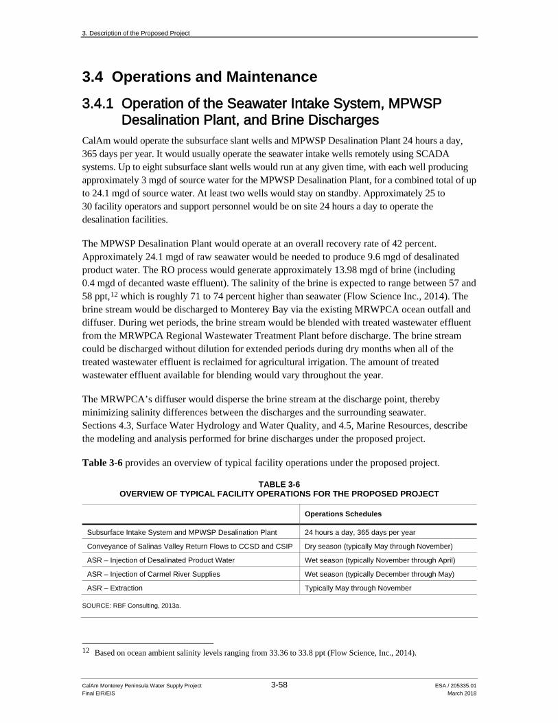
3. Description of the Proposed Project
CalAm Monterey Peninsula Water Supply Project 3-58 ESA / 205335.01 Final EIR/EIS March 2018
3.4 Operations and Maintenance
3.4.1 Operation of the Seawater Intake System, MPWSP Desalination Plant, and Brine Discharges
CalAm would operate the subsurface slant wells and MPWSP Desalination Plant 24 hours a day, 365 days per year. It would usually operate the seawater intake wells remotely using SCADA systems. Up to eight subsurface slant wells would run at any given time, with each well producing approximately 3 mgd of source water for the MPWSP Desalination Plant, for a combined total of up to 24.1 mgd of source water. At least two wells would stay on standby. Approximately 25 to 30 facility operators and support personnel would be on site 24 hours a day to operate the desalination facilities.
The MPWSP Desalination Plant would operate at an overall recovery rate of 42 percent. Approximately 24.1 mgd of raw seawater would be needed to produce 9.6 mgd of desalinated product water. The RO process would generate approximately 13.98 mgd of brine (including 0.4 mgd of decanted waste effluent). The salinity of the brine is expected to range between 57 and 58 ppt,12 which is roughly 71 to 74 percent higher than seawater (Flow Science Inc., 2014). The brine stream would be discharged to Monterey Bay via the existing MRWPCA ocean outfall and diffuser. During wet periods, the brine stream would be blended with treated wastewater effluent from the MRWPCA Regional Wastewater Treatment Plant before discharge. The brine stream could be discharged without dilution for extended periods during dry months when all of the treated wastewater effluent is reclaimed for agricultural irrigation. The amount of treated wastewater effluent available for blending would vary throughout the year.
The MRWPCA’s diffuser would disperse the brine stream at the discharge point, thereby minimizing salinity differences between the discharges and the surrounding seawater. Sections 4.3, Surface Water Hydrology and Water Quality, and 4.5, Marine Resources, describe the modeling and analysis performed for brine discharges under the proposed project.
Table 3-6 provides an overview of typical facility operations under the proposed project.
TABLE 3-6 OVERVIEW OF TYPICAL FACILITY OPERATIONS FOR THE PROPOSED PROJECT
Operations Schedules
Subsurface Intake System and MPWSP Desalination Plant 24 hours a day, 365 days per year Conveyance of Salinas Valley Return Flows to CCSD and CSIP Dry season (typically May through November) ASR – Injection of Desalinated Product Water Wet season (typically November through April) ASR – Injection of Carmel River Supplies Wet season (typically December through May) ASR – Extraction Typically May through November
SOURCE: RBF Consulting, 2013a.
12 Based on ocean ambient salinity levels ranging from 33.36 to 33.8 ppt (Flow Science, Inc., 2014).

3. Description of the Proposed Project
CalAm Monterey Peninsula Water Supply Project 3-59 ESA / 205335.01 Final EIR/EIS March 2018
Over the life of the project, for a host of reasons (e.g., mechanical or electrical problems, water quality issues13, loss of power, etc.), there would be periods when CalAm would need to shut down the MPWSP Desalination Plant. After a shutdown, CalAm might operate the plant with all RO modules in service (at the plant’s maximum production capacity of 11.2 mgd) to catch up on production; however, the total annual production would not exceed 9.6 mgd (Svindland, 2014).
Table 3-7 provides a comparative example of MPWSP Desalination Plant typical daily versus operations following a 2-day shutdown. As shown in the example, any fluctuations in daily production would not affect total monthly production.
TABLE 3-7 MPWSP DESALINATION PLANT OPERATIONS –
NORMAL OPERATIONS VS. RECOVERY POST 2-DAY SHUTDOWN
Week
Daily Production (mgd)
Monday Tuesday Wednesday Thursday Friday Saturday Sunday
Normal Operations
1 9.6 9.6 9.6 9.6 9.6 9.6 9.6 2 9.6 9.6 9.6 9.6 9.6 9.6 9.6 3 9.6 9.6 9.6 9.6 9.6 9.6 9.6 4 9.6 9.6 9.6 9.6 9.6 9.6 9.6
Total Monthly Production = 269 mgd Operations Before and After 2-Day Shutdown
1 9.6 9.6 9.6 9.6 9.6 9.6 9.6 2 9.6 ***2-Day Shutdown*** 11.2 11.2 11.2 11.2 3 11.2 11.2 11.2 11.2 11.2 11.2 11.2 4 9.6 9.6 9.6 9.6 9.6 9.6 9.6
Total Monthly Production = 267 mgd SOURCE: Svindland, 2014.
The slant wells would require maintenance every 5 years. During maintenance, workers would access the well from the wellhead, and would lower mechanical brushes into the wells to clean the screens. If chemical cleaning products are needed for maintenance, only environmentally inert products would be used. The disturbance area associated with periodic maintenance of the subsurface slant wells would be roughly 6 acres. All disturbance would occur on the inland side of the dune face at the wellheads.
Accounting for all of the slant wells, maintenance activities within the beach area would last between 9 and 18 weeks every 5 years. Maintenance activities would occur between October and February to avoid the nesting season for snowy plover. Maintenance workers would access the slant wells via the existing CEMEX access road (RBF Consulting, 2013a).
13 Hazardous Algal Blooms would not be a reason for the wells to stop operating. Subsurface intakes are not affected
by algal blooms.
3. Description of the Proposed Project
CalAm Monterey Peninsula Water Supply Project 3-60 ESA / 205335.01 Final EIR/EIS March 2018
3.4.2 Operation of the ASR System Carmel River supplies would be injected into the groundwater basin via ASR under the MPWMD’s and CalAm’s existing SWRCB Permits 20808A and 20808C. The instantaneous rate and cumulative quantity of water diverted from the Carmel River and placed into underground storage would be measured and recorded, as would the cumulative quantity of Carmel River water recovered from underground storage and placed into beneficial use.
Unlike the injection period for Carmel River supplies, which is limited to periods of high flow between December and May in the lower stretches of the Carmel River, desalinated product water supplies could be injected into the Seaside Groundwater Basin during any time of the year. Desalinated product water and Carmel River supplies would typically be pumped out of the basin during summer months and periods of peak demand.
Similar to existing operations, CalAm proposes to use the ASR system to store water supplies during wet periods. Both desalinated product water and Carmel River supplies would be chlorinated to drinking water standards at existing CalAm treatment facilities prior to injection. Desalinated product water would flow through the new Desalinated Water Pipeline and the new Transmission Main, while Carmel River supplies would be conveyed through the existing Segunda Pipeline, and injected into the northern subbasin of the Seaside Groundwater Basin (see Section 4.4, Groundwater Resources, for descriptions of groundwater basins and subbasins in the project area).
CalAm would rely primarily on any of the six ASR injection/extraction wells (Phases I, II, and III of the ASR system) to recover the banked water. Depending on demand, CalAm would also use existing groundwater production wells in the Seaside Groundwater Basin to recover the banked water. This would increase operational flexibility. CalAm would extract the water via existing production wells under the following conditions to avoid changing the hydraulic gradient or exacerbating localized depressions:
• Seaside Groundwater Basin annual monitoring reports prepared by Seaside Groundwater Basin Watermaster would be reviewed yearly to identify the current location of the groundwater depression in the Santa Margarita Formation, the aquifer unit where the ASR system water would be banked.
• CalAm’s use of existing groundwater production wells to recover water stored in the ASR system would be limited to those production wells in the northern subbasin located east of the center point of the groundwater depression. Restricting extraction to the eastern side of the groundwater depression would allow CalAm to extract the banked water before it migrates into the depression and would, therefore, avoid affecting the groundwater depression.
• The order in which the groundwater production wells would be used to extract banked water depends on how close they are to the ASR injection wells. The first priority would be any of the ASR wells, followed in order by the Paralta, Ord Grove #2, Luzern #2, and Playa #3 Wells.14
14 Based on the current location of the groundwater depression in 2012, and until the depression migrates to the west,
the Playa #3 Well may not be used to recover water banked in the ASR system.
3. Description of the Proposed Project
CalAm Monterey Peninsula Water Supply Project 3-61 ESA / 205335.01 Final EIR/EIS March 2018
• Existing groundwater production wells located outside of the northern subbasin of the Seaside Groundwater Basin (Plumas #4 Well) would not be used to recover banked water because these wells are not directly connected to the aquifer where the ASR water would be stored (CalAm, 2014b).
The stored water would be pumped out of the groundwater basin and conveyed through the ASR Conveyance Pipeline to the CalAm distribution system for direct delivery to customers in Seaside and other customers in CalAm’s Monterey District service area. CalAm would meet drinking water requirements by disinfecting this water before serving it to customers.
Tanker trucks would deliver sodium hypochlorite solution (12.5 percent NaOCl) to the existing ASR disinfection facility about once each month to replenish the system. With all six wells in operation, the expected chemical use would be less than 150 gallons per day of sodium hypochlorite. The ASR system would be operated remotely via SCADA.
Similar to operations for the existing ASR injection/extraction wells, facility operators would regularly backflush accumulated sediment and turbid water from the ASR-5 and ASR-6 Wells. This would take anywhere from a few minutes to 2 hours. CalAm would route the water produced during routine backflushing to the existing ASR settling basin at the ASR-1 and ASR-2 Wells site, near the intersection of General Jim Moore Boulevard and Coe Avenue.
3.4.3 Desalinated Water Conveyance Facilities
3.4.3.1 Routine Maintenance of Pump Stations and Pipelines The proposed pump station could operate continuously for up to 24 hours a day. Although pump stations would typically be operated remotely via SCADA, facility operators would conduct routine visits to the pump station site to monitor operations, conduct general maintenance activities, and service the pumps.
General operations and maintenance activities associated with pipelines would include annual inspections of the cathodic protection system and replacement of sacrificial anodes when necessary, testing and servicing of valves, vegetation maintenance along rights-of-way, and repairs of minor leaks in buried pipeline joints or segments.
3.4.3.2 Interconnections for Highway 68 Satellite Systems With implementation of the proposed project, the Ryan Ranch, Hidden Hills, and Bishop satellite systems would stop pumping groundwater from the Laguna Seca Subbasin and would rely on MPWSP supplies instead.
3.4.4 Payback to Seaside Groundwater Basin As part of the adjudication of the Seaside Groundwater Basin, CalAm must provide replenishment water supplies to the basin in an amount equivalent to the quantity of water that CalAm previously
3. Description of the Proposed Project
CalAm Monterey Peninsula Water Supply Project 3-62 ESA / 205335.01 Final EIR/EIS March 2018
pumped in excess of the basin’s natural safe yield.15 In November 2012, the Seaside Groundwater Basin Watermaster and CalAm tentatively agreed to a replenishment schedule of 25 years at a replenishment rate of 700 afy, based on a running 5-year (water year) average. CalAm would meet its obligations via in-lieu recharge or artificial replenishment. Depending on fluctuations in precipitation and water supplies, the actual volume of water replenished during any given year would vary but would be equal to or greater than 700 afy based on a running 5-year average (Watermaster, 2012).
3.4.5 Power Demand Under existing conditions, the electrical power needed to operate the water supply system in CalAm’s Monterey District Service Area is 11,466,000 kilowatt hours per year (kWh/yr). That is the baseline electrical demand for the proposed project. With the proposed project, and accounting for the reduction in Carmel River pumping that would occur once the MPWSP Desalination Plant is brought online, the average annual power demand for the Monterey District Service Area would be 63,364,000 kWh/yr. Therefore, the net increase in annual electrical power demand for water production would be approximately 51,898,000 kWh/yr. Electrical power for all of the proposed project facilities would be provided via the PG&E power grid unless CalAm were to secure a separate renewable power source for some or all of its power needs.
The MPWSP would recover energy from the brine stream using pressure-exchanger technology.16 Energy recovery is a process through which the energy contained in pressurized brine flow is transferred to a portion of the RO source water. This lowers source water pumping requirements and thus lowers overall energy consumption. Under the proposed project, energy recovery using pressure-exchanger technology would substantially reduce overall energy consumption during the RO process. This reduced consumption is reflected in the estimate of annual electrical power demand in the previous paragraph.
3.5 Permits, Approvals, and Regulatory Requirements This EIR/EIS is intended to inform decision-makers of the environmental consequences associated with the proposed MPWSP. The proposed project would be subject to various regulations and could require discretionary permits from federal, state, and local jurisdictions. Table 3-8 summarizes the permits and authorizations that would likely be required to build, operate, and maintain the proposed project. Chapter 4, Environmental Setting, Impacts, and Mitigation Measures, explains how the project follows the applicable state, regional, and local plans relevant to each topical section in the chapter.
15 As defined in Monterey County Superior Court’s final decision in Case No. 66343, California American Water v.
City of Seaside, et al. (Monterey County Superior Court, 2006), and as amended decision in February 2007 (Monterey County Superior Court, 2007), “natural safe yield” is the quantity of groundwater in the Seaside Groundwater Basin that occurs solely as a result of natural replenishment.
16 Additional information on pressure-exchanger energy recovery systems is available at www.energyrecovery.com.

3. Description of the Proposed Project
CalAm Monterey Peninsula Water Supply Project 3-63 ESA / 205335.01 Final EIR/EIS March 2018
TABLE 3-8 ANTICIPATED PERMITS AND APPROVALS
Agency or Department Permit or Approval Discussion
Federal Agencies – Consultations with federal agencies could be required if the proposed project is subject to a federal permit, such as a Clean Water Act Section 404 permit.
U.S. Army Corps of Engineers (Corps)
Permit under Section 404 of the Clean Water Act (33 USC §1344) Section 10 Permit of the Rivers and Harbors Act of 1899
• Projects that would discharge dredged or fill material into waters of the United States, including wetlands, require a Corps permit under Clean Water Act Section 404.
• Projects that would place structures below the Ordinary High Water elevation of navigable waters of the United States require approval by the Corps.
U.S. Fish and Wildlife Service (USFWS)
For “May Affect, but May Not Adversely Affect” determinations: A letter of Concurrence is issued by USFWS to federal action agency For “May Adversely Affect” determinations: Biological Opinion under Section 7 of the Federal Endangered Species Act (FESA) (16 USC §1531 et seq.) and Incidental Take Statement in accordance with FESA Section 7, as amended (16 USC §1531 et seq.)
• The Federal Endangered Species Act (FESA) requires federal agencies to consult with the USFWS before implementing actions that may affect a federally listed species under their jurisdiction or may adversely modify designated critical habitat. MBNMS, as NEPA Lead Agency, must consult with the USFWS to determine whether the proposed action of issuing permits and authorizations for the proposed project is likely to adversely affect a federally-listed terrestrial or freshwater animal or plant species under USFWS jurisdiction, or that species’ designated critical habitat; jeopardize the continued existence of species that are proposed for listing under FESA; or adversely modify proposed critical habitat. To support the USFWS determination, MBNMS prepared a Biological Assessment to initiate “formal consultation”. The USFWS will issue a Biological Opinion concerning the effects of the project. If the USFWS finds that the project may jeopardize the species or destroy or modify critical habitat, reasonable and prudent alternatives to the action must be considered.
• The USFWS authorizes the incidental take of federally listed species through an Incidental Take Statement that is supported by, and often attached to, the Biological Opinion, consistent with Section 7 of the FESA.
Permit under the Migratory Bird Treaty Act (16 USC §§703–711)
• The incidental take of migratory birds or any part, nest, or eggs of a migratory bird also requires an Incidental Take Permit from the USFWS.
National Oceanic and Atmospheric Administration (NOAA) National Marine Fisheries Service (NMFS)
For “May Affect, but May Not Adversely Affect” determinations: A letter of Concurrence is issued by NMFS to federal action agency For “May Adversely Affect” determinations: Biological Opinion under Section 7 of the Federal Endangered Species Act (FESA) (16 USC §1531 et seq.) and Incidental Take Statement in accordance with FESA Section 7, as amended (16 USC §1531 et seq.)
• The Federal Endangered Species Act (FESA) requires federal agencies to consult with the NMFS before implementing actions that may affect a federally listed species under their jurisdiction or may adversely modify designated critical habitat. MBNMS, as NEPA Lead Agency, must consult with the NMFS to determine whether the proposed action of issuing permits and authorizations for the proposed project is likely to adversely affect a federally-listed marine species under NMFS jurisdiction, or that species’ designated critical habitat; jeopardize the continued existence of species that are proposed for listing under FESA; or adversely modify proposed critical habitat. To support the NMFS determination, MBNMS prepared a Biological Assessment to initiate consultation.
• The NMFS issued a letter of concurrence on October 23, 2017.

3. Description of the Proposed Project
CalAm Monterey Peninsula Water Supply Project 3-64 ESA / 205335.01 Final EIR/EIS March 2018
TABLE 3-8 (Continued) ANTICIPATED PERMITS AND APPROVALS
Agency or Department Permit or Approval Discussion
Federal Agencies (cont.)
State Historic Preservation Office
Consultation with State Historic Preservation Officer (SHPO) or Tribal Historic Preservation Officer (THPO) under Section 106 of the National Historic Preservation Act of 1966 (NHPA) (16 USC §470 et seq.)
• The NHPA requires federal permitting agencies to “take into account” the effects of a federal undertaking, or a proposed project, on properties included in the National Register of Historic Places or that meet National Register criteria, and to afford the Advisory Council on Historic Preservation a reasonable opportunity to comment. Thus, as part of the federal consultations required by NEPA, the MBNMS must consult with the SHPO or THPO on behalf of the project applicant.
• The SHPO issued a letter of concurrence on May 3, 2017
National Oceanic and Atmospheric Administration (NOAA)
Under the National Marine Sanctuaries Act and regulations, a permit or other approval is required from NOAA to allow a person to conduct an activity within a sanctuary that is otherwise prohibited.
• Otherwise prohibited activities within a national marine sanctuary may be allowed via the issuance of a permit or authorization. A special use permit (SUP) is available pursuant to Section 310 of the NMSA for any activity that is necessary (1) to establish conditions of access to and use of any Sanctuary resource or (2) to promote public use and understanding of a Sanctuary resource; and that does not injure Sanctuary resource. An authorization is available to allow the conduct of an activity prohibited by sanctuary regulations if such activity is specifically authorized by any valid federal, State, or local lease, permit, license, approval, or other authorization issued after the effective date of sanctuary regulation (15 CFR 922.49).
Consultation with NMFS under Section 305(b) of the Magnuson-Stevens Fishery Conservation and Management Act (16 USC §1855(b))
• If MBNMS approves a project that could adversely affect designated Essential Fish Habitat (EFH), it must consult with NMFS.
• The NMFS issued a letter of concurrence on October 23, 2017.
U.S. Army Real property outgrants for construction and operation for non-Army users (Army Regulation (AR) 405-80, 200-1)
• AR405-80 sets forth the authority and prescribes policies for management of the United States of America title to real property under the jurisdiction or control of the Department of the Army, granting the use of that real property to non-Army users.
• Under AR200-1, real property transactions require preparation of appropriate NEPA documentation per 32 Code of Federal Regulations (CFR) 651. Should a discretionary approval be required for use of U.S. Army property, this EIR/EIS will serve as the NEPA requirement for the action.
State Agencies
California Public Utilities Commission (CPUC)
Certificate of Public Convenience and Necessity (Cal. Pub. Util. Code §1001 et seq.)
• This allows the applicant to build and operate the proposed project, and to recover its costs.
Fort Ord Reuse Authority (FORA)
Finding of substantial conformance with the Base Reuse Plan and the FORA Master Resolution Chapter 8 consistency criteria
• Applications for local agency legislative land use planning approval (such as a proposed county general plan amendment) come before the FORA Board of Directors for a determination of consistency between the application and the Base Reuse Plan.

3. Description of the Proposed Project
CalAm Monterey Peninsula Water Supply Project 3-65 ESA / 205335.01 Final EIR/EIS March 2018
TABLE 3-8 (Continued) ANTICIPATED PERMITS AND APPROVALS
Agency or Department Permit or Approval Discussion
State Agencies (cont.)
Central Coast Regional Water Quality Control Board (RWQCB)
Compliance with National Pollutant Discharge Elimination System (NPDES) General Permit for Discharges of Storm Water Associated with Construction Activity (Order 2010-0014-DWQ)
• Any discharge of stormwater to surface waters of the United States from a construction project that encompasses 1 acre or more of soil disturbance requires compliance with the General Permit. This includes: − Development and implementation of a stormwater pollution prevention plan that specifies
best management practices (BMPs) to prevent construction pollutants from contacting stormwater, with the intent of keeping all products of erosion from moving offsite into receiving waters
− Elimination or reduction of non-stormwater discharges to storm sewer systems and other waters of the U.S.
− Inspection of all BMPs
NPDES permit under Section 402 of the Clean Water Act (33 USC §1342)
• Discharges of brine into surface waters of the United States, including wetlands and Monterey Bay National Marine Sanctuary, requires an NPDES permit. The Waste Discharge Requirements for the Monterey Regional Water Pollution Control Agency Treatment Plant (Order No. R3-2014-0013, NPDES Permit No. CA0048551) would be revised to include the brine discharges from the MPWSP Desalination Plant.
Waste Discharge Requirements under the Porter-Cologne Water Quality Control Act (Cal. Water Code §13000 et seq.)
• Any activity that results or may result in a discharge of waste that directly or indirectly impacts the quality of waters of the state (including groundwater or surface water) or the beneficial uses of those waters is subject to waste discharge requirements.
Water Quality Certification under Section 401 of the Clean Water Act (33 USC §1341)
• Under Section 401 of the Clean Water Act, the RWQCB must certify that actions authorized under Section 404 of the Clean Water Act also meet state water quality standards. Any applicant for a federal license or permit to conduct any activity including, but not limited to, the construction or operation of facilities, which may result in any discharge into navigable waters, must provide the licensing or permitting agency a certification that the activity meets state water quality standards.
California Department of Fish and Wildlife (CDFW)
Incidental Take Permit under the California Endangered Species Act (CESA) (Cal. Fish and Game Code §2081)
• The take of any endangered, threatened, or candidate species may be permitted if it is incidental to an otherwise lawful activity and if the impacts of the authorized take are minimized and fully mitigated. No permit may be issued if the activity would jeopardize the continued existence of the species.
Lake/Streambed Alteration Agreement (Cal. Fish and Game Code §1602)
• It is unlawful to substantially divert, obstruct, or change the natural flow or the bed, channel, or bank of any river, stream, or lake in California that supports wildlife resources, or to use any material from the streambeds, without first notifying the CDFW.
California Coastal Commission (CCC)
Coastal Development Permit under the California Coastal Act (Cal. Pub. Res. Code §30000 et seq.)
• Development proposed within the Coastal Zone requires a Coastal Development Permit from the CCC, except where the local jurisdiction has approved a Local Coastal Program (LCP). If so, the primary responsibility for issuing permits in coastal areas shifts from the CCC to the local government, although the CCC will hear appeals on certain local government coastal development decisions.

3. Description of the Proposed Project
CalAm Monterey Peninsula Water Supply Project 3-66 ESA / 205335.01 Final EIR/EIS March 2018
TABLE 3-8 (Continued) ANTICIPATED PERMITS AND APPROVALS
Agency or Department Permit or Approval Discussion
State Agencies (cont.)
California Coastal Commission (CCC) (cont.)
• Regardless of whether a Coastal Development Permit must be obtained from a local agency under an approved LCP, the CCC retains coastal development permit authority over new development proposed on the immediate shoreline, including intake and outfall structures on tidelands, submerged lands, and certain public trust lands, and over any development that constitutes a “major public works project.” (Cal. Pub. Res. Code §§30601, 30600[b][2]).
Federal Consistency Review under the Coastal Zone Management Act (16 U.S.C. §1456) and Federal Consistency regulations (15 C.F.R. Part 930, Subpart D)
• In accordance with 15 C.F.R. Part 930, Subpart D, the project applicant may be required to submit a federal consistency certification to the CCC. The CCC must then concur, conditionally concur, or object to the certification; no response from the CCC would be considered a presumed concurrence.
California Environmental Protection Agency, State Water Resources Control Board, Division of Drinking Water
Permit to Operate a Public Water System (Cal. Health and Safety Code §116525)
• The Division of Drinking Water has permitting authority over the operation of a public water system and oversees the quality of the desalinated water produced.
California Department of Transportation (Caltrans)
Encroachment Permit (Cal. Streets and Highway Code §660 et seq.)
• Caltrans has permitting authority over encroachments in, under, or over any portion of a state highway right-of-way, including Highway 156, Highway 68, and Highway 1.
California Department of Toxic Substances Control (DTSC)
DTSC hazardous waste management and disposal requirements under Title 22, Division 4.5, Chapter 11, Article 3, Soluble Threshold Limits Concentrations (STLC)/Total Threshold Limits Concentrations (TTLC); Review under local regulations for digging and excavation within certain areas of the former Ft Ord.
• DTSC would require soil management plans if contaminated soils are present along the pipeline alignment. Regulatory Requirements outline the concentrations at which soil and groundwater are a California Hazardous Waste. Title 22 would apply if contaminated soil or groundwater arising from trenching are a Hazardous Waste, subject to associated transport and disposal requirements. Under 40 CFR Part 261, concentrations of contaminated soil or groundwater may also be a Federal Hazardous Waste.
• DTSC must approve digging and excavation in certain portions of the former Fort Ord military base (also see City of Seaside Digging and Excavation Permit).
California State Lands Commission (CSLC)
New Land Use Lease, for portion of the subsurface slant wells located below mean high tide, and Amended Land Use Lease, for use of the MRWPCA outfall and diffuser (Cal. Pub. Res. Code §1900)
• CSLC has jurisdiction and management authority over all ungranted tidelands and submerged lands in Monterey Bay under the Common Law Public Trust. On tidal waterways, the State’s sovereign fee ownership extends landward to the mean high tide elevation.
California Department of Parks and Recreation
Easement, right-of-entry (ROE) and/or lease negotiations for 0.25 mile portion of the new Transmission Main that encroaches on Fort Ord Dunes State Park
• State Parks has jurisdiction and management authority over Fort Ord Dunes State Park and any easement, ROE and/or lease if granted, will need to be appraised using DGS guidelines and be accompanied by State Parks-approved legal descriptions.
State Water Resources Control Board (SWRCB)
Order approving change in Place of Use to allow Carmel River water to be injected and/or extracted by ASR-5 and ASR-6 wells
• The SWRCB has authority over the place of injection and use of Carmel River water under Permit 20808

3. Description of the Proposed Project
CalAm Monterey Peninsula Water Supply Project 3-67 ESA / 205335.01 Final EIR/EIS March 2018
TABLE 3-8 (Continued) ANTICIPATED PERMITS AND APPROVALS
Agency or Department Permit or Approval Discussion
Local Agencies
Seaside Groundwater Basin Watermaster
Permit for Injection/Extraction • The Seaside Groundwater Basin Watermaster must approve injection/extraction activities that would affect the Seaside Groundwater Basin.
City of Seaside Digging and Excavation Permit • Excavations of more than 10 cubic yards within an Ordnance Remediation District, in the Former Fort Ord areas require a permit under Chapter 15.34, Digging and Excavation, of the Former Fort Ord Ordinance. Permit approval is subject to requirements placed on the property by an agreement between the City of Seaside, FORA, and DTSC.
City of Marina Coastal Development Permit in accordance with the California Coastal Act (Cal. Pub. Res. Code §30000 et seq.)
• Where the City of Marina has jurisdiction through a Local Coastal Program, it must permit development proposed in the Coastal Zone, and the CCC retains jurisdiction over appeals. Where there is no Local Coastal Program, the CCC retains primary permit authority.
Monterey County Public Works Department
Encroachment Permit (Monterey County Code [MCC] Chapter 14.04)
• Designated activities within the right-of-way of a county highway require an Encroachment Permit from the director of the Public Works Department, whose decisions may be appealed to the Monterey County Board of Supervisors.
Tree Removal Permit • Removal of any protected trees requires a tree removal permit under Chapter 16.60 of the County’s municipal code. Removal of more than three protected trees requires a forest management plan from the Director of Planning.
Monterey County Health Department, Environmental Health Division
Well Construction Permit (MCC Chapter 15.08)
• Monterey County's health officer must issue a written permit before anyone can build new water supply wells. Those decisions may be appealed to the Board of Supervisors.
Permit to Construct Desalination Facility (MCC Chapter 10.72)
• Monterey County's director of environmental health, or their designee, must issue a permit before anyone can build or operate a desalination treatment facility (MCC Section 10.72.010). Permit decisions may be appealed to the director of environmental health within 30 days (MCC Section 10.72.080).
Monterey County Planning and Building Inspection Department
Conditional Use Permit (MCC Chapter 21.74)
• The Monterey County Zoning Ordinance requires a conditional use permit issued by the appropriate planning authority (e.g., the zoning administrator or the Planning Commission) for certain uses in specific zones. The permit decisions may be respectively appealed to the Planning Commission or the Board of Supervisors.
Coastal Development Permit in accordance with the California Coastal Act (Cal. Pub. Res. Code §30000 et seq.)
• Where the County has jurisdiction through a Local Coastal Program, it must permit development proposed in the Coastal Zone, and the CCC retains jurisdiction over appeals. Where there is no Local Coastal Program, the CCC retains primary permit authority.
Grading Permit (MCC Chapter 16.08)
• Subject to certain exceptions, grading requires a permit from the Monterey County Planning and Building Inspection Department. Grading permit decisions may be appealed to the five-member Board of Appeals, and then to the Board of Supervisors.
Digging and Excavation Permit (MCC Chapter 16.10)
• A separate permit from the Monterey County Planning and Building Inspection Department is required for any project activities within the former Fort Ord military base. Permit decisions may be appealed to the Board of Appeals and then to the Board of Supervisors.

3. Description of the Proposed Project
CalAm Monterey Peninsula Water Supply Project 3-68 ESA / 205335.01 Final EIR/EIS March 2018
TABLE 3-8 (Continued) ANTICIPATED PERMITS AND APPROVALS
Agency or Department Permit or Approval Discussion
Local Agencies (cont.)
Monterey County Planning and Building Inspection Department (cont.)
Erosion Control Permit (MCC Chapter 16.12)
• The Director of Building Inspection must issue an Erosion Control Permit for any project development and construction activities (such as site cleaning, grading, and soil removal or placement) that are causing or are likely to cause accelerated erosion. Permit decisions may be appealed to the Board of Appeals and then to the Board of Supervisors.
Monterey Peninsula Water Management District (MPWMD)
Water System Expansion permit under with Ordinance 96 of the MPWMD Board of Directors
• Any project activity that would expand the water delivery system within the MPWMD’s jurisdiction requires a permit.
Monterey Bay Unified Air Pollution Control District
Authority to Construct permit under Local Rule 3.1
• Projects that propose to build, erect, alter, or replace any article, machine, equipment, or other contrivance that may emit air contaminants from a stationary source or may be used to eliminate, reduce, or control air contaminant emissions require an authorization to construct permit.
Permit to Operate under Local Rule 3.2 • Operating the diesel fuel-powered emergency generators, and any other articles, machines, equipment, or other contrivances that may emit air contaminants from a stationary source requires a permit to operate.
City of Monterey, City of Seaside, City of Marina, City of Pacific Grove
Land Use (including local coastal development permit(s), as necessary), Building, Public Health, Public Works, Tree/Vegetation Removal, and Encroachment Permits, and/or similar department approvals to those discussed above in the context of Monterey County, each issued in accordance with the applicable city’s municipal code
• See related discussions provided in the context of Monterey County.
Transportation Agency for Monterey County (TAMC)
Encroachment Permit • An encroachment permit is necessary to install conveyance pipelines along the TAMC right-of-way.
NOTES: CFR = Code of Federal Regulations PRC = Public Resources Code USC = United States Code MCC = Monterey County Code
_________________________
3. Description of the Proposed Project
CalAm Monterey Peninsula Water Supply Project 3-69 ESA / 205335.01 Final EIR/EIS March 2018
References – Description of the Proposed Project California American Water Company (CalAm), 2013a. Project A-2, System Interconnections.
January 2013.
California American Water Company (CalAm), 2013b. San Clemente Dam Removal & Carmel River Reroute Project Website. Available online at: www.sanclementedamremoval.org. Accessed November 1, 2013.
California American Water Company (CalAm), 2014a. Responses to March 31, 2014 Request for Information.
California American Water Company (CalAm), 2014b. Letter from Eric Sabolsice and Rich Svindland, CalAm, to Eric Zigas, Environmental Science Associates. “Operations Rules for the Injection and Extraction of Desalinated Water into ASR Well System.” Dated May 2, 2014.
California American Water Company (CalAm), 2014c. Proposed Water Portfolio Data plus energy spreadsheet provided to CPUC by John T. Kilpatrick on March 12, 2014.
CDM Smith, 2014. Technical Proposal for Design-Build of the Monterey Peninsula Water Supply Project Desalination Infrastructure, Section 3.0 Technical Proposal. October 16, 2013.
Central Coast Water Shed Studies (CCoWS), 2009. Fall 2008 Stage-Volume Relationship for Los Padres Reservoir, Carmel River, California. Publication No. WI-2009-2. May 8, 2009.
Denise Duffy & Associates, Inc. 2012. Addendum to the Phase I ASR Environmental Impact Report/Environmental Assessment and Initial Study Checklist for Full Implementation of Aquifer Storage and Recovery (ASR) Water Project 2. Prepared for Monterey Peninsula Water Management District. April 11, 2012.
California Department of Water Resources (DWR), 2012. Final Supplement to the Environmental Impact Report for the San Clemente Dam Seismic Safety Project, July 2012.
Flow Science, Inc. 2014. MRWPCA Brine Discharge Diffuser Analysis FSI 134032 Draft Technical Memorandum. August 29, 2014.
Geoscience, 2017, Summary of Offshore/Onshore Well Lengths for Various Years, August 2.
Monterey County Superior Court, 2006. California American Water, Plaintiff, vs. City of Seaside, City of Monterey, et al., Case No. M66343, Decision. Filed March 27, 2006.
Monterey County Superior Court, 2007. California American Water, Plaintiff, vs. City of Seaside, et al., Case No. M66343, Amended Decision, February 9, 2007.
Monterey Peninsula Water Management District (MPWMD), 2005. Monterey Peninsula, Carmel Bay, and South Monterey Bay Integrated Regional Water Management Plan and Integrated Coastal Watershed Management Plan, Seaside Groundwater Basin Aquifer Storage and Recovery (ASR) Phase I, July 5, 2005.

3. Description of the Proposed Project
CalAm Monterey Peninsula Water Supply Project 3-70 ESA / 205335.01 Final EIR/EIS March 2018
Monterey Regional Water Pollution Control Agency (MRWPCA), 2017. Brine Mixing Facility Brine Waste Disposal Study. Prepared by E2 Consulting Engineers, Inc. May 1, 2017.
RBF Consulting, 2010. Final Environmental Assessment and Findings of No Significant Impact, Monterey Bay Regional Water Project – Aquifer Storage and Recovery. Prepared for U.S. Army Garrison, Presidio of Monterey, and California American Water. September 2010.
RBF Consulting, 2013a. Memorandum: Recommended Capacity for the Monterey Peninsula Water Supply Project (MPWSP) Desalination Plant. January 7, 2013.
RBF Consulting, 2013b. Monterey Peninsula Water Supply Project (MPWSP) Project Description Update. January 9, 2013.
RBF Consulting, 2013c. Monterey Peninsula Water Supply Project (MPWSP) Capital and O&M Cost Estimate Update. January 9, 2013.
RBF Consulting, 2013d. MPWSP Temporary Slant Test Well Project Description, June 25, 2013.
Regional Water Quality Control Board (RWQCB), Central Coast Region, 2008. General Waiver for Specific Types of Discharges (Resolution No. R3-2008-0010). May 9, 2008.
Regional Water Quality Control Board (RWQCB), Central Coast Region, 2011. Waste Discharge Requirements National Pollutant Discharge Elimination System (NPDES) General Permit for Discharges with Low Threat to Water Quality. Order No. R3-2011-0223, NPDES Permit No. CAG993001. December 1, 2011.
Regional Water Quality Control Board (RWQCB), Central Coast Region, 2014. Waste Discharge Requirements for the Monterey Regional Water Pollution Control Agency Treatment Plant (Order No. R3-2014-0013, NPDES Permit No. CA0048551)
Seaside Groundwater Basin Watermaster, 2012. Meeting Minutes from November 29, 2012 Board Meeting.
State Water Resources Control Board (SWRCB), 1995. Order No. WR 95-10: Order on Four Complaints Files Against The California-American Water Company, Carmel River, Monterey County. July 6, 1995.
Svindland, Richard, 2014. Email from Richard Svindland, Vice President of Engineering at California American Water Company, to Kelly White, Senior Project Manager at Environmental Science Associates. “Desal Plant Planned Feedwater Supply Requirements.” Dated May 30, 2014.