chapter 3 applying job files - topptopo a/s · applying job files before beginning to work with the...
TRANSCRIPT
Chapter 3
Applying Job Files
Before beginning to work with the 3Dxi™ excavator system, you must have job files that contain the various information needed to accurately grade the jobsite. The job files you need include control point files and design surface file. Using 3Dxi, you can also create a plane surface model to use for the design surface.Creating a Control Point FileThe first task, when setting up the 3Dxi on a new jobsite, is to create a new control point file. You can use either Pocket-3D or the GX-60 control box to create your Control Point files.
The control point file consists of descriptions, local site coordinates, global GPS coordinates, and units of measurements for each control point located on the site. Typically, the project’s survey team provides control point information after accurately measuring these points with a surveying instrument.
The control point file created here may be tentative, but will provide a beginning from which to create a more thorough file later. When performing localization, the control box processes the GPS information as the operator sits in the cab.
NOTICE
The accuracy of the surveyor’s measurements for local site coordinates of control points directly affects the quality of grade.
TIP
If a control point file is already available, use a USB device to copy it to the GX-60 (see “Copying Files” on page 5-26 for details).
P/N 7010-0696 3-1
Applying Job Files
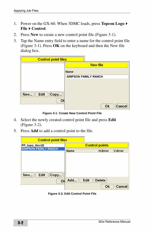
1. Power on the GX-60. When 3DMC loads, press Topcon Logo File Control.
2. Press New to create a new control point file (Figure 3-1).
3. Tap the Name entry field to enter a name for the control point file (Figure 3-1). Press OK on the keyboard and then the New file dialog box.
Figure 3-1. Create New Control Point File
4. Select the newly created control point file and press Edit (Figure 3-2).
5. Press Add to add a control point to the file.
Figure 3-2. Edit Control Point File
3Dxi Reference Manual3-2
Creating a Control Point File
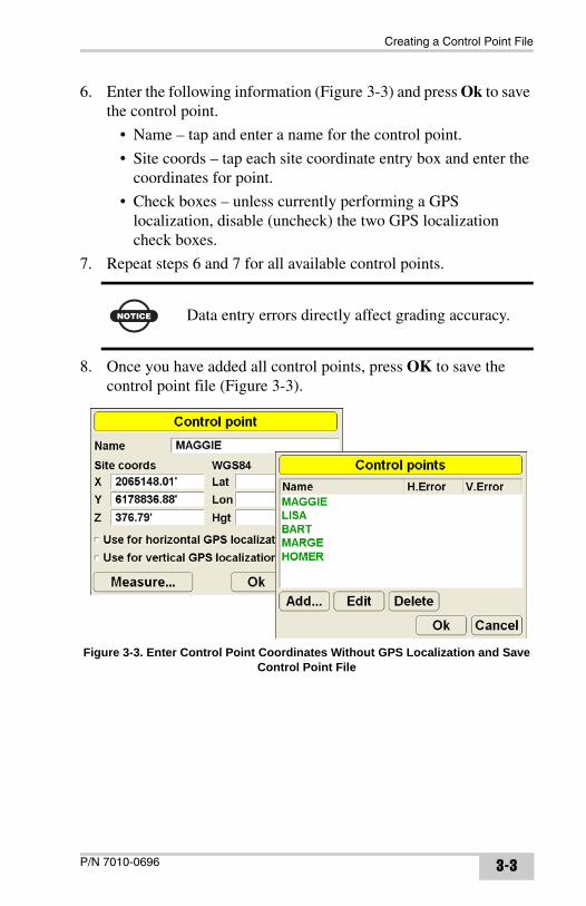
6. Enter the following information (Figure 3-3) and press Ok to save the control point.
• Name – tap and enter a name for the control point.
• Site coords – tap each site coordinate entry box and enter the coordinates for point.
• Check boxes – unless currently performing a GPS localization, disable (uncheck) the two GPS localization check boxes.
7. Repeat steps 6 and 7 for all available control points.
8. Once you have added all control points, press OK to save the control point file (Figure 3-3).
Figure 3-3. Enter Control Point Coordinates Without GPS Localization and Save Control Point File
NOTICE Data entry errors directly affect grading accuracy.
P/N 7010-0696 3-3
Applying Job Files
Selecting a Design Surface FileFor 3Dxi applications, the project engineer provides a Design Surface file for the jobsite. Before grading, the correct file must be copied from a USB storage device to the GX-60 and selected (see “Copying Files” on page 5-26 for details).
Once the GX-60 control box contains the correct Design Surface file, select it and apply it to the machine. Available Design Surface files depends on the jobsite and project.
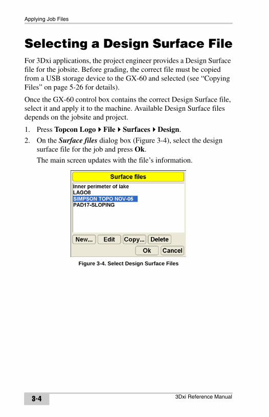
1. Press Topcon Logo File Surfaces Design.
2. On the Surface files dialog box (Figure 3-4), select the design surface file for the job and press Ok.
The main screen updates with the file’s information.
Figure 3-4. Select Design Surface Files
3Dxi Reference Manual3-4
Creating a Plane Surface Model
Creating a Plane Surface ModelThe 3Dxi 3DMC software has the ability to create a plane surface model using a unique, on-site method. The plane surface model is created on the machine, in real-time, and can be used as a Design Surface file for grading. Unlike conventional applications using a laser, using 3Dxi to create a surface model eliminates the required, repetitive setup of a transmitter at the job site.
The plane surface model is composed of four basic factors: a mainfall orientation, a mainfall grade, a crossfall grade, and a reference elevation point on the plane. Just like aligning the rotating laser plane and adjusting the laser receiver height, the operator needs to be prepared with a set of relative information to fulfill the four factors. This information is composed of three points: A, B, and an elevation reference point.
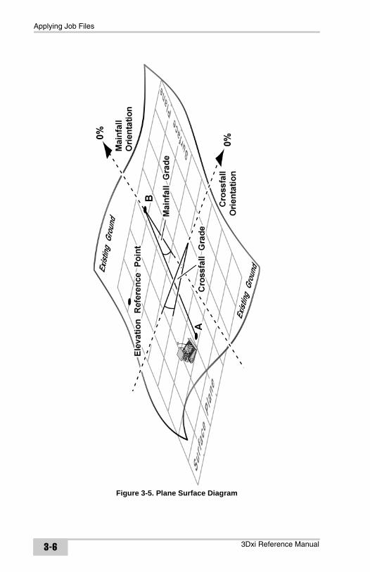
Figure 3-5 on page 3-6 illustrates the basic factors needed for a plane surface model.
The following is the most common method using three reference points prepared at the site: two points (A and B) are measured to determine a mainfall orientation, and the other point (elevation reference point) is measured to determine an elevation.
P/N 7010-0696 3-5
Applying Job Files
Figure 3-5. Plane Surface Diagram
3Dxi Reference Manual3-6
Creating a Plane Surface Model
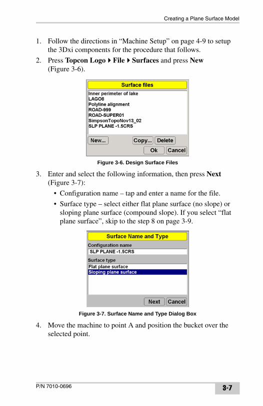
1. Follow the directions in “Machine Setup” on page 4-9 to setup the 3Dxi components for the procedure that follows.
2. Press Topcon Logo File Surfaces and press New (Figure 3-6).
Figure 3-6. Design Surface Files
3. Enter and select the following information, then press Next (Figure 3-7):
• Configuration name – tap and enter a name for the file.
• Surface type – select either flat plane surface (no slope) or sloping plane surface (compound slope). If you select “flat plane surface”, skip to the step 8 on page 3-9.
Figure 3-7. Surface Name and Type Dialog Box
4. Move the machine to point A and position the bucket over the selected point.
P/N 7010-0696 3-7
Applying Job Files
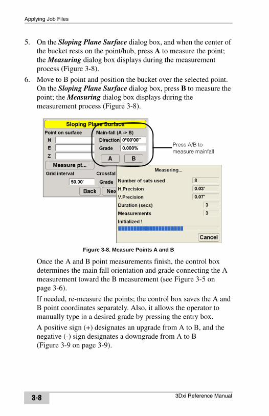
5. On the Sloping Plane Surface dialog box, and when the center of the bucket rests on the point/hub, press A to measure the point; the Measuring dialog box displays during the measurement process (Figure 3-8).
6. Move to B point and position the bucket over the selected point. On the Sloping Plane Surface dialog box, press B to measure the point; the Measuring dialog box displays during the measurement process (Figure 3-8).
Figure 3-8. Measure Points A and B
Once the A and B point measurements finish, the control box determines the main fall orientation and grade connecting the A measurement toward the B measurement (see Figure 3-5 on page 3-6).
If needed, re-measure the points; the control box saves the A and B point coordinates separately. Also, it allows the operator to manually type in a desired grade by pressing the entry box.
A positive sign (+) designates an upgrade from A to B, and the negative (-) sign designates a downgrade from A to B (Figure 3-9 on page 3-9).
Press A/B to measure mainfall
3Dxi Reference Manual3-8
Creating a Plane Surface Model
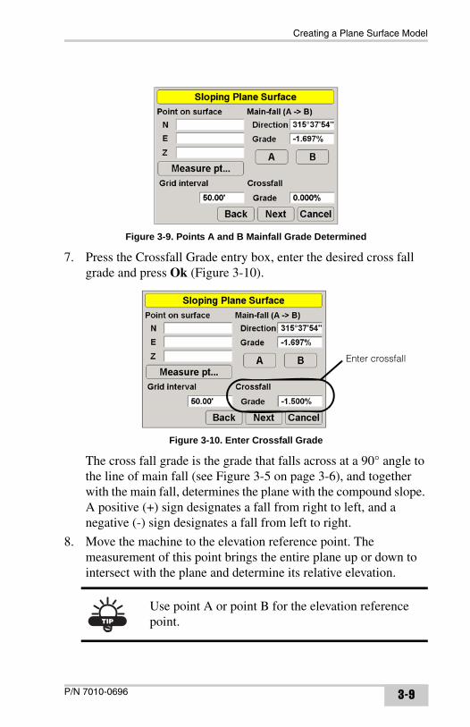
Figure 3-9. Points A and B Mainfall Grade Determined
7. Press the Crossfall Grade entry box, enter the desired cross fall grade and press Ok (Figure 3-10).
Figure 3-10. Enter Crossfall Grade
The cross fall grade is the grade that falls across at a 90° angle to the line of main fall (see Figure 3-5 on page 3-6), and together with the main fall, determines the plane with the compound slope. A positive (+) sign designates a fall from right to left, and a negative (-) sign designates a fall from left to right.
8. Move the machine to the elevation reference point. The measurement of this point brings the entire plane up or down to intersect with the plane and determine its relative elevation.
TIP
Use point A or point B for the elevation reference point.
Enter crossfall
P/N 7010-0696 3-9
Applying Job Files
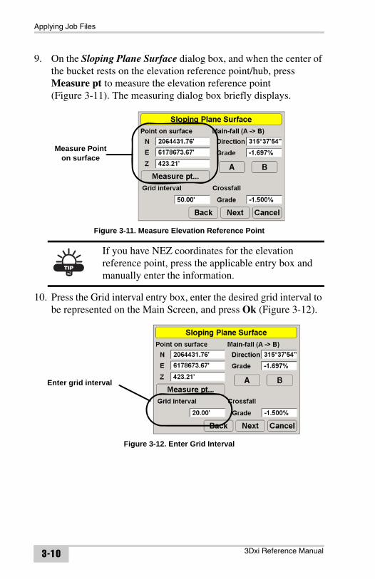
9. On the Sloping Plane Surface dialog box, and when the center of the bucket rests on the elevation reference point/hub, press Measure pt to measure the elevation reference point (Figure 3-11). The measuring dialog box briefly displays.
Figure 3-11. Measure Elevation Reference Point
10. Press the Grid interval entry box, enter the desired grid interval to be represented on the Main Screen, and press Ok (Figure 3-12).
Figure 3-12. Enter Grid Interval
TIP
If you have NEZ coordinates for the elevation reference point, press the applicable entry box and manually enter the information.
Measure Pointon surface
Enter grid interval
3Dxi Reference Manual3-10
Creating a Plane Surface Model
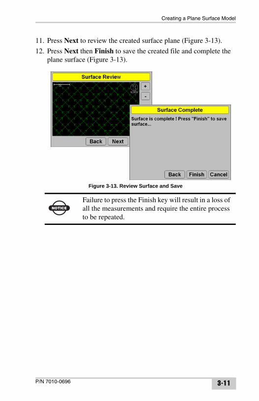
11. Press Next to review the created surface plane (Figure 3-13).
12. Press Next then Finish to save the created file and complete the plane surface (Figure 3-13).
Figure 3-13. Review Surface and Save
NOTICE
Failure to press the Finish key will result in a loss of all the measurements and require the entire process to be repeated.
P/N 7010-0696 3-11
Applying Job Files
Notes:
3Dxi Reference Manual3-12
Chapter 4
Jobsite Setup
For indicate applications, first set up the machine components, then setup and initialize the Base Station, and finally, localize the GPS coordinates before grading. Several of the following sections assume an initial setup of components is being performed. If most of the components are attached and localization has been completed, simply connect any removable components, turn on the control box, and perform an accuracy test to ensure consistent grade.Equipment Setup: Base StationThe Base Station always sets up over a Control Point on the jobsite; to ensure accuracy, the Base Station GPS+ antenna must be positioned directly over the top of the Control Point.
The Base Station can be set up and taken down on a daily basis, or can be mounted on a permanently fixed pole and left for the duration of the project. A permanent setup prevents errors due to incorrect antenna height measurements.
When setting up the Base Station, make sure you select the correct point from the Control Points file and verify the point has a northing, easting, and elevation coordinate. The more accurate these coordinates are, the tighter the control while grading.
• Install the Base Station over a control point – see page 4-2
• Measure the antenna height – see page 4-6
• Connect all Base Station components – see page 4-4
• Select the correct radio settings – see page 4-6 (refer to your Base Station’s documentation for radio configuration procedures)
• Initialize the Base station – see page 4-6
Figure 4-2 on page 4-4 shows a completed Base Station setup.
P/N 7010-0696 4-1
Jobsite Setup
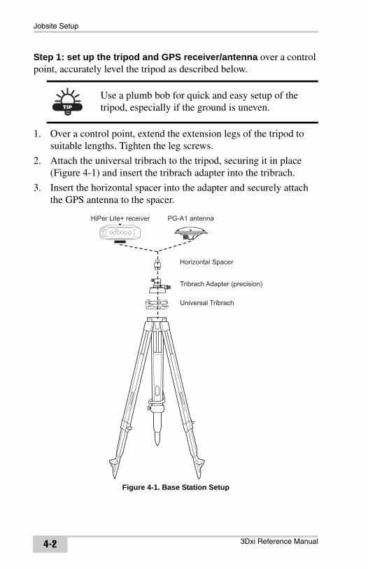
Step 1: set up the tripod and GPS receiver/antenna over a control point, accurately level the tripod as described below.
1. Over a control point, extend the extension legs of the tripod to suitable lengths. Tighten the leg screws.
2. Attach the universal tribrach to the tripod, securing it in place (Figure 4-1) and insert the tribrach adapter into the tribrach.
3. Insert the horizontal spacer into the adapter and securely attach the GPS antenna to the spacer.
Figure 4-1. Base Station Setup
TIP
Use a plumb bob for quick and easy setup of the tripod, especially if the ground is uneven.
Horizontal Spacer
Tribrach Adapter (precision)
Universal Tribrach
PG-A1 antennaHiPer Lite+ receiver
3Dxi Reference Manual4-2
Equipment Setup: Base Station
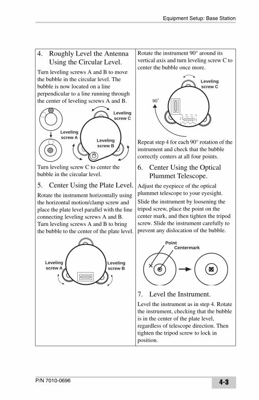
4. Roughly Level the Antenna Using the Circular Level.
Turn leveling screws A and B to move the bubble in the circular level. The bubble is now located on a line perpendicular to a line running through the center of leveling screws A and B.
Turn leveling screw C to center the bubble in the circular level.
5. Center Using the Plate Level.Rotate the instrument horizontally using the horizontal motion/clamp screw and place the plate level parallel with the line connecting leveling screws A and B. Turn leveling screws A and B to bring the bubble to the center of the plate level.
Rotate the instrument 90° around its vertical axis and turn leveling screw C to center the bubble once more.
Repeat step 4 for each 90° rotation of the instrument and check that the bubble correctly centers at all four points.
6. Center Using the Optical Plummet Telescope.
Adjust the eyepiece of the optical plummet telescope to your eyesight.
Slide the instrument by loosening the tripod screw, place the point on the center mark, and then tighten the tripod screw. Slide the instrument carefully to prevent any dislocation of the bubble.
7. Level the Instrument.Level the instrument as in step 4. Rotate the instrument, checking that the bubble is in the center of the plate level, regardless of telescope direction. Then tighten the tripod screw to lock in position.
Levelingscrew C
Levelingscrew A Leveling
screw B
Levelingscrew A
Levelingscrew B
90
Levelingscrew C
PointCentermark
P/N 7010-0696 4-3
Jobsite Setup
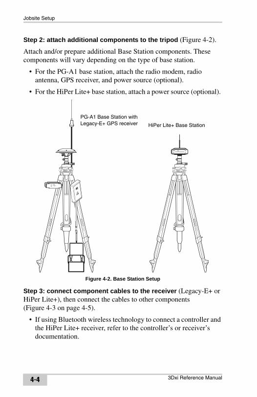
Step 2: attach additional components to the tripod (Figure 4-2).
Attach and/or prepare additional Base Station components. These components will vary depending on the type of base station.
• For the PG-A1 base station, attach the radio modem, radio antenna, GPS receiver, and power source (optional).
• For the HiPer Lite+ base station, attach a power source (optional).
Figure 4-2. Base Station Setup
Step 3: connect component cables to the receiver (Legacy-E+ or HiPer Lite+), then connect the cables to other components (Figure 4-3 on page 4-5).
• If using Bluetooth wireless technology to connect a controller and the HiPer Lite+ receiver, refer to the controller’s or receiver’s documentation.
PG-A1 Base Station with Legacy-E+ GPS receiver HiPer Lite+ Base Station
3Dxi Reference Manual4-4
Equipment Setup: Base Station
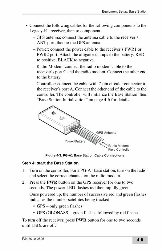
• Connect the following cables for the following components to the Legacy-E+ receiver, then to component:
– GPS antenna: connect the antenna cable to the receiver’s ANT port, then to the GPS antenna.
– Power: connect the power cable to the receiver’s PWR1 or PWR2 port. Attach the alligator clamps to the battery: RED to positive, BLACK to negative.
– Radio Modem: connect the radio modem cable to the receiver’s port C and the radio modem. Connect the other end to the battery.
– Controller: connect the cable with 7-pin circular connector to the receiver’s port A. Connect the other end of the cable to the controller. The controller will initialize the Base Station. See “Base Station Initialization” on page 4-6 for details.
Figure 4-3. PG-A1 Base Station Cable Connections
Step 4: start the Base Station
1. Turn on the controller. For a PG-A1 base station, turn on the radio and select the correct channel on the radio modem.
2. Press the PWR button on the GPS receiver for one to two seconds. The power LED flashes red then rapidly green.
Once powered up, the number of successive red and green flashes indicates the number satellites being tracked.
• GPS – only green flashes
• GPS+GLONASS – green flashes followed by red flashes
To turn off the receiver, press PWR button for one to two seconds until LEDs are off.
GPS Antenna
Radio ModemField Controller
Power/Battery
P/N 7010-0696 4-5
Jobsite Setup
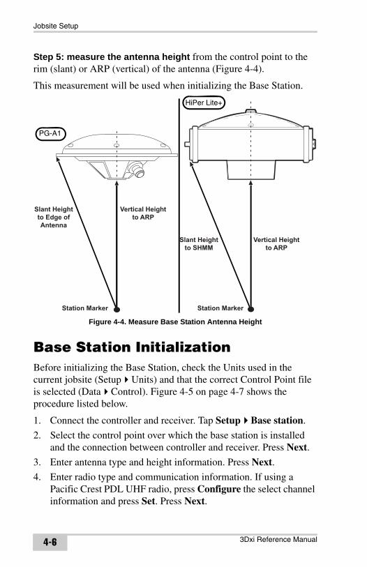
Step 5: measure the antenna height from the control point to the rim (slant) or ARP (vertical) of the antenna (Figure 4-4).
This measurement will be used when initializing the Base Station.
Figure 4-4. Measure Base Station Antenna Height
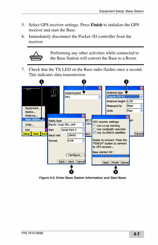
Base Station InitializationBefore initializing the Base Station, check the Units used in the current jobsite (Setup Units) and that the correct Control Point file is selected (Data Control). Figure 4-5 on page 4-7 shows the procedure listed below.
1. Connect the controller and receiver. Tap Setup Base station.
2. Select the control point over which the base station is installed and the connection between controller and receiver. Press Next.
3. Enter antenna type and height information. Press Next.
4. Enter radio type and communication information. If using a Pacific Crest PDL UHF radio, press Configure the select channel information and press Set. Press Next.
Vertical Heightto ARP
Station Marker
Slant Heightto SHMM
Vertical Heightto ARP
Slant Heightto Edge ofAntenna
Station Marker
PG-A1
HiPer Lite+
3Dxi Reference Manual4-6
Equipment Setup: Base Station
5. Select GPS receiver settings. Press Finish to initialize the GPS receiver and start the Base.
6. Immediately disconnect the Pocket-3D controller from the receiver.
7. Check that the TX LED on the Base radio flashes once a second. This indicates data transmission.
Figure 4-5. Enter Base Station Information and Start Base
CAUTION
Performing any other activities while connected to the Base Station will convert the Base to a Rover.
1 2 3
4 5
P/N 7010-0696 4-7
Jobsite Setup
General Base Station Setup Rules and Notes
• Every time the Base Station is setup, a new slant measurement must be taken since the height of the antenna will be different.
Unless a fixed-height tripod, or something permanent, is used. Then you only need to measure the height of the antenna once. You will need to use Pocket-3D only for the initial processing since the GPS receiver will remember the initial settings. However, if any setting stored in the receiver has been changed or reset (like a reset function), you will need to re-initialize the Base Station.
• When the GPS receiver tracks a sufficient number of satellites, the receiver takes only a few seconds to process and report a successful start. See “Troubleshooting 3Dxi Components” on page 6-4 if the receiver fails to respond or fails to initialize.
• Ideally, the Base Station should be placed in an area free of object that can obstruct signals from satellites and degrade positioning accuracy. Obstructions can include trees, buildings, vehicles, or fences.
• Ideally, the radio antenna should not be placed too close to the GPS receiver. For large job sites, or sites with hilly terrain, use a tall tripod or a sturdy structure to raise the radio antenna as high as possible for better radio transmission range.
3Dxi Reference Manual4-8
Machine Setup
Machine SetupMachine setup for 3Dxi excavator control application is quick and easy. First install the MC-A1 and Radio antennas, next install the MC-2.5 Receiver Box, the attach the GX-60 control box, and lastly connect the cables.
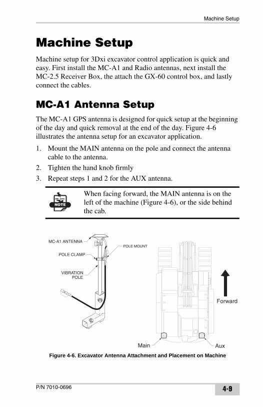
MC-A1 Antenna SetupThe MC-A1 GPS antenna is designed for quick setup at the beginning of the day and quick removal at the end of the day. Figure 4-6 illustrates the antenna setup for an excavator application.
1. Mount the MAIN antenna on the pole and connect the antenna cable to the antenna.
2. Tighten the hand knob firmly
3. Repeat steps 1 and 2 for the AUX antenna.
Figure 4-6. Excavator Antenna Attachment and Placement on Machine
NOTE
When facing forward, the MAIN antenna is on the left of the machine (Figure 4-6), or the side behind the cab.
Main Aux
Forward
P/N 7010-0696 4-9
Jobsite Setup
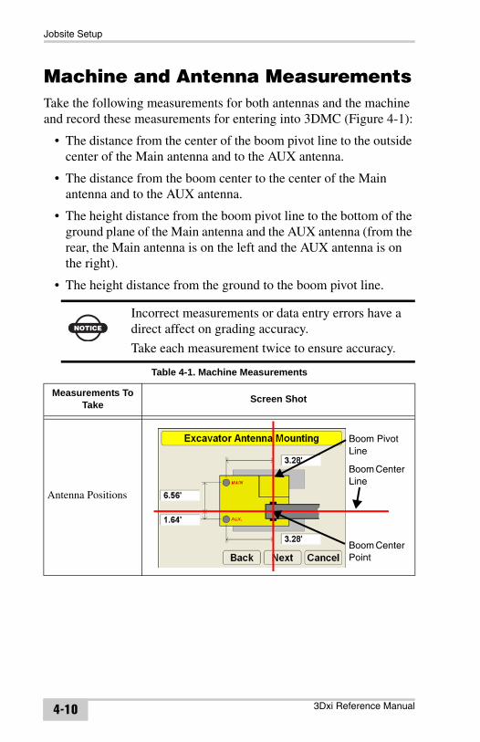
Machine and Antenna MeasurementsTake the following measurements for both antennas and the machine and record these measurements for entering into 3DMC (Figure 4-1):
• The distance from the center of the boom pivot line to the outside center of the Main antenna and to the AUX antenna.
• The distance from the boom center to the center of the Main antenna and to the AUX antenna.
• The height distance from the boom pivot line to the bottom of the ground plane of the Main antenna and the AUX antenna (from the rear, the Main antenna is on the left and the AUX antenna is on the right).
• The height distance from the ground to the boom pivot line.
NOTICE
Incorrect measurements or data entry errors have a direct affect on grading accuracy.
Take each measurement twice to ensure accuracy.
Table 4-1. Machine Measurements
Measurements To Take Screen Shot
Antenna Positions
Boom Pivot Line
Boom Center Line
Boom Center Point
3Dxi Reference Manual4-10
Machine Setup
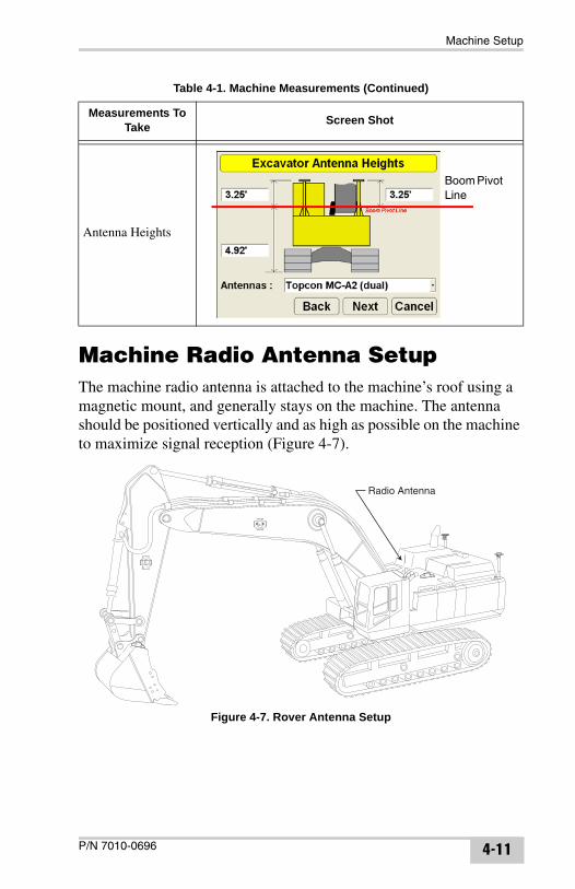
Machine Radio Antenna SetupThe machine radio antenna is attached to the machine’s roof using a magnetic mount, and generally stays on the machine. The antenna should be positioned vertically and as high as possible on the machine to maximize signal reception (Figure 4-7).
Figure 4-7. Rover Antenna Setup
Antenna Heights
Table 4-1. Machine Measurements (Continued)
Measurements To Take Screen Shot
Boom Pivot Line
Radio Antenna
P/N 7010-0696 4-11
Jobsite Setup
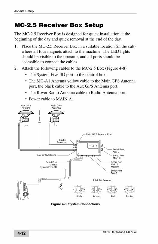
MC-2.5 Receiver Box SetupThe MC-2.5 Receiver Box is designed for quick installation at the beginning of the day and quick removal at the end of the day.
1. Place the MC-2.5 Receiver Box in a suitable location (in the cab) where all four magnets attach to the machine. The LED lights should be visible to the operator, and all ports should be accessible to connect the cables.
2. Attach the following cables to the MC-2.5 Box (Figure 4-8):
• The System Five-3D port to the control box.
• The MC-A1 Antenna yellow cable to the Main GPS Antenna port, the black cable to the Aux GPS Antenna port.
• The Rover Radio Antenna cable to Radio Antenna port.
• Power cable to MAIN A.
Figure 4-8. System Connections
TS-1 Tilt Sensors
Body Boom Stick Bucket
Aux GPS Antenna
Serial PortMain A
System Five-3D
Main GPS Antenna Port
Serial PortMain BModemSerial PortAux-A
Serial PortMain C
RadioAntenna
Serial PortAux-C
Aux GPSAntenna
Main GPSAntenna
3Dxi Reference Manual4-12
Machine Setup
Control Box SetupThe GX-60 control box is designed for quick attachment at the beginning of the day and quick removal at the end of the day.
1. Attach the control box to the in-cab mounting.
2. Connect the electrical cable to the top serial port (Figure 4-8).
3. Turn on the control box and allow the system to boot up.
Machine Configuration File for 3DxiThe machine configuration file provides vital information about the type of machine, the setup of the components on the machine, machine measurements, and radio configuration information.
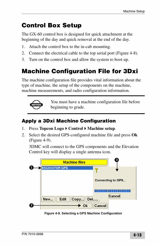
Apply a 3Dxi Machine Configuration1. Press Topcon Logo Control Machine setup.
2. Select the desired GPS-configured machine file and press Ok (Figure 4-9).
3DMC will connect to the GPS components and the Elevation Control key will display a single antenna icon.
Figure 4-9. Selecting a GPS Machine Configuration
NOTICEYou must have a machine configuration file before beginning to grade.
1
2
3
P/N 7010-0696 4-13
Jobsite Setup
Create a 3Dxi Machine ConfigurationFor 3Dxi applications, select and enter antenna, bucket, and radio information.
1. With the control box on, press Topcon Logo Control Machine setup to display the Machine files dialog box (Figure 4-10 on page 4-15).
2. Press New to begin creating a machine configuration file (Figure 4-10 on page 4-15). Enter the following information and press Next:
• Configuration name – tap the entry box to display the alphanumeric keyboard. Type a name for the machine configuration and press OK.
• Sensor – only “GPS antenna” available.
• Location – only “Middle” available.
• Units of measure – select the unit of measure (meters, feet, inches, centimeters).
TIP
A simple check ensures that the machine receives corrections from the Base station: if the Elevation Control Key is green, the system is ready.
If the key is red or a status icon is crossed out, check the machine cable connections.See “Troubleshooting 3Dxi Components” on page 6-4 for further information.
TIP
Read the following procedure to determine the machine measurements required. Then have the measurements ready to enter when creating a machine configuration.
3Dxi Reference Manual4-14

Machine Setup
Figure 4-10. Create Machine Configuration File
3. For the next six to nine screens, depending on the type of machine and it’s setup, see Appendix A. This chapter describes entering machine and antenna measurements, as well as calibrating the sensors. This information should already have been entered by the field manager or installer at this point.
NOTICE
Incorrect measurements or data entry errors have a direct affect on grading accuracy.
Take each measurement twice to ensure accuracy.
Table 4-2. Machine Measurements
Measurements Screen Shot
Antenna Positions
Boom Pivot Line
Boom Center Line
Boom Center Point
P/N 7010-0696 4-15
Jobsite Setup
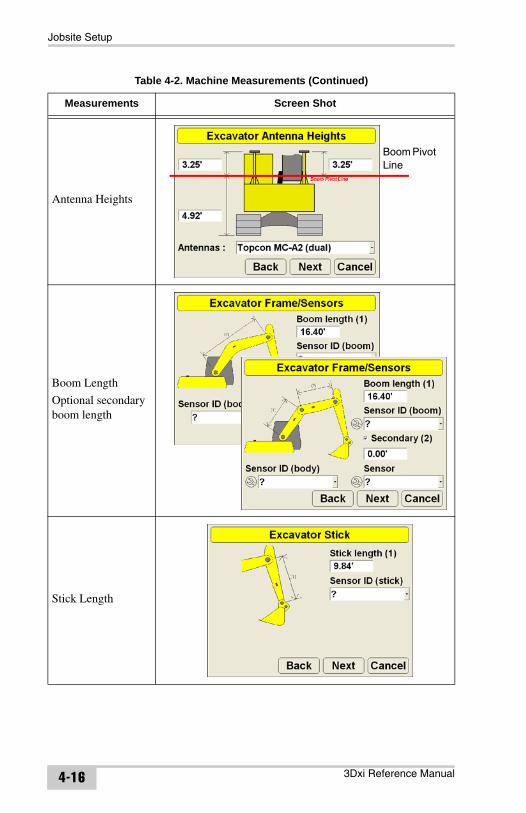
Antenna Heights
Boom Length
Optional secondary boom length
Stick Length
Table 4-2. Machine Measurements (Continued)
Measurements Screen Shot
Boom Pivot Line
3Dxi Reference Manual4-16
Machine Setup
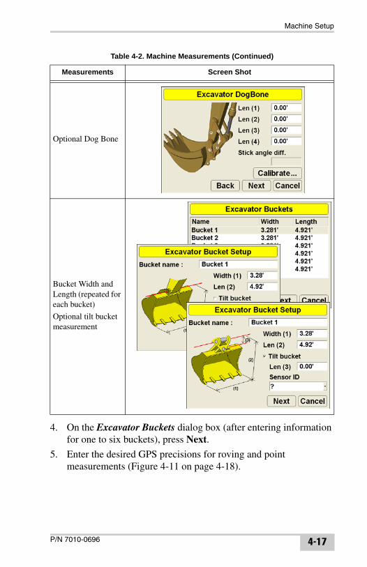
4. On the Excavator Buckets dialog box (after entering information for one to six buckets), press Next.
5. Enter the desired GPS precisions for roving and point measurements (Figure 4-11 on page 4-18).
Optional Dog Bone
Bucket Width and Length (repeated for each bucket)
Optional tilt bucket measurement
Table 4-2. Machine Measurements (Continued)
Measurements Screen Shot
P/N 7010-0696 4-17
Jobsite Setup
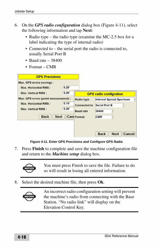
6. On the GPS radio configuration dialog box (Figure 4-11), select the following information and tap Next:
• Radio type – the radio type (examine the MC-2.5 box for a label indicating the type of internal radio)
• Connected to – the serial port the radio is connected to, usually Serial Port B
• Baud rate – 38400
• Format – CMR
Figure 4-11. Enter GPS Precisions and Configure GPS Radio
7. Press Finish to complete and save the machine configuration file and return to the Machine setup dialog box.
8. Select the desired machine file, then press Ok.
NOTICEYou must press Finish to save the file. Failure to do so will result in losing all entered information.
NOTICE
An incorrect radio configuration setting will prevent the machine’s radio from connecting with the Base Station. “No radio link” will display on the Elevation Control Key.
3Dxi Reference Manual4-18
GPS Localization
GPS LocalizationAfter you have set up all the hardware components and initialized the Base Station, you need to localize the GPS coordinates to the jobsite’s coordinates.
This section gives information on the principles of GPS localization and methods of GPS localization, as well as the procedures needed to localize using either Pocket-3D and an RTK Rover system, or the GX-60 control box and machine.
Principles of GPS LocalizationThe GPS system is capable of precise positioning, but the positions it computes are relative to a global reference system defined in terms of a geographic latitude, longitude and height above (a representation of) the earth’s surface. To be useful for local site work, global GPS coordinates need to be converted into local site coordinates, defined in terms of a distance north and east of some origin point and some distance above an elevation datum. These north, east, and elevation coordinates (often abbreviated to NEZ coordinates) may be those of a regional coordinate system—e.g., a state plane system in the United States—or the project’s survey crew may arbitrarily define these coordinates for the specific site. NEZ coordinates must be defined in terms of the construction design data. In either case, a mathematical conversion is necessary to turn global GPS coordinates into NEZ coordinates relative to the locally defined coordinate system.
The basic approach to calculating the mathematical conversion is to provide pairs of point coordinates for each control point on the project. A point pair consists of the following coordinates:
• local NEZ coordinates for the point (obtained from the project’s survey crew)
• global latitude, longitude, and height coordinates for the point (measured as described in this section or obtained from the project’s survey crew)
These point pairs are needed to calculate a precise mathematical conversion formula for converting all global GPS coordinates
P/N 7010-0696 4-19
Jobsite Setup
generated in the GPS receiver to local NEZ coordinates for a particular project.
The following steps will help to ensure a high-quality localization suitable for centimeter-level machine grading with 3Dxi.
• First, the surveyor’s local control points must be precisely measured. The quality of measurements directly affects grade accuracy.
• Second, the control points need to be located more or less evenly around the site. Generally, the more control points the better, but if they are clustered together or are all at one section of the site, the results will be less than ideal.
A good rule of success is to locate control points evenly distributed around a perimeter of the site or grading area. While not directly related to quality of localization, locate control points that are elevated, easily accessible, and are not frequently obstructed by trees, buildings, other structures, moving vehicles, etc.
• GPS localization requires a minimum of three control points, but at least four or more points should be used for the localization.
Entering Localized GPS CoordinatesGPS localization is processed in the control point file created prior to beginning each project. This control point file contains the formula necessary for the mathematical conversion between global GPS coordinates and NEZ coordinates. The control point file can be localized by entering global GPS coordinates directly into the GX-60 control box. One of the following sources can measure points and provide coordinates:
• Each control point is measured with a Topcon GPS+ or GPS RTK Survey Rover System and Pocket-3D.
• A third party source provides GPS coordinates.
If the control point file in 3DMC needs to be updated with localized coordinates, the operator can enter global GPS coordinates directly into the GX-60 control box. The control box then processes the localization as the operator sits in the cab.
3Dxi Reference Manual4-20
GPS Localization
Because this method deals with control point files, see “Creating a Control Point File” on page 3-1 for further information.
1. Power on the control box and allow the 3DMC application program start up. Have the measurements for each Control Point available.
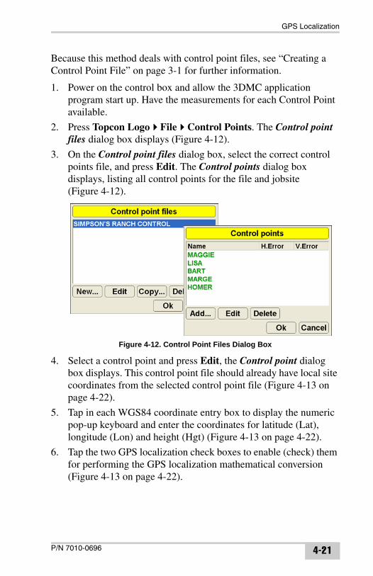
2. Press Topcon Logo File Control Points. The Control point files dialog box displays (Figure 4-12).
3. On the Control point files dialog box, select the correct control points file, and press Edit. The Control points dialog box displays, listing all control points for the file and jobsite (Figure 4-12).
Figure 4-12. Control Point Files Dialog Box
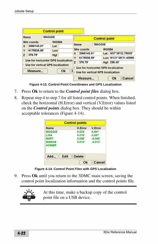
4. Select a control point and press Edit, the Control point dialog box displays. This control point file should already have local site coordinates from the selected control point file (Figure 4-13 on page 4-22).
5. Tap in each WGS84 coordinate entry box to display the numeric pop-up keyboard and enter the coordinates for latitude (Lat), longitude (Lon) and height (Hgt) (Figure 4-13 on page 4-22).
6. Tap the two GPS localization check boxes to enable (check) them for performing the GPS localization mathematical conversion (Figure 4-13 on page 4-22).
P/N 7010-0696 4-21
Jobsite Setup
Figure 4-13. Control Point Coordinates and GPS Localization
7. Press Ok to return to the Control point files dialog box.
8. Repeat step 4 to step 7 for all listed control points. When finished, check the horizontal (H.Error) and vertical (V.Error) values listed on the Control points dialog box. They should be within acceptable tolerances (Figure 4-14).
Figure 4-14. Control Point Files with GPS Localization
9. Press Ok until you return to the 3DMC main screen, saving the control point localization information and the control points file.
TIP
At this time, make a backup copy of the control point file on a USB device.
3Dxi Reference Manual4-22