chapter 28 ipv4 - arista networks€¦ · supplies an unrequested update of arp information. in a...
TRANSCRIPT
1715
Chapter 28
IPv4Arista switches support Internet Protocol version 4 (IPv4) and Internet Protocol version 6 (IPv6) forrouting packets across network boundaries. This chapter describes Arista’s implementation of IPv4and includes these sections:
• Section 28.1: IPv4 Addressing
• Section 28.2: IPv4 Routing
• Section 28.3: IPv4 Multicast Counters
• Section 28.4: Route Management
• Section 28.5: IPv4 Route Scale
• Section 28.6: IP Source Guard
• Section 28.7: DHCP Relay Across VRF
• Section 28.8: IP NAT
• Section 28.9: TCP MSS Clamping
• Section 28.10: IPv4 GRE Tunneling
• Section 28.11: IPv4 Commands
28.1 IPv4 AddressingEach IPv4 network device is assigned a 32-bit IP address that identifies its network location. Thesesections describe IPv4 address formats, data structures, configuration tasks, and display options:
• Section 28.1.1: IPv4 Address Formats
• Section 28.1.2: IPv4 Address Configuration
• Section 28.1.3: Address Resolution Protocol (ARP)
• Section 28.1.4: Displaying ARP Entries
28.1.1 IPv4 Address Formats
IPv4 addresses are composed of 32 bits, expressed in dotted decimal notation by four decimalnumbers, each ranging from 0 to 255. A subnet is identified by an IP address and an address spacedefined by a routing prefix. The switch supports the following subnet formats:
• IP address and subnet mask: The subnet mask is a 32-bit number (dotted decimal notation) thatspecifies the subnet address space. The subnet address space is calculated by performing anAND operation between the IP address and subnet mask.
1716
IPv4 Addressing Chapter 28: IPv4
• IP address and wildcard mask: The wildcard mask is a 32-bit number (dotted decimal notation)that specifies the subnet address space. Wildcard masks differ from subnet masks in that the bitsare inverted. Some commands use wildcard masks instead of subnet masks.
• CIDR notation: CIDR notation specifies the scope of the subnet space by using a decimal numberto identify the number of leading ones in the routing prefix. When referring to wildcard notation,CIDR notation specifies the number of leading zeros in the routing prefix.
Example
• These subnets (subnet mask and CIDR notation) are calculated identically:
10.24.154.13 255.255.255.010.24.154.13/24
The defined space includes all addresses between 10.24.154.0 and 10.24.154.255.
• These subnets (wildcard mask and CIDR notation) are calculated identically:
124.17.3.142 0.0.0.15124.17.3.142/28
The defined space includes all addresses between 124.17.3.128 and 124.17.3.143.
28.1.2 IPv4 Address Configuration
Assigning an IPv4 Address to an Interface
The ip address command specifies the IPv4 address of an interface and the mask for the subnet towhich the interface is connected.
Example
• These commands configure an IPv4 address with subnet mask for VLAN 200:
switch(config)#interface vlan 200switch(config-if-Vl200)#ip address 10.0.0.1/24switch(config-if-Vl200)#
28.1.3 Address Resolution Protocol (ARP)
Address Resolution Protocol (ARP) is a protocol that maps IP addresses to MAC addresses that localnetwork devices recognize. The ARP cache is a table that stores the correlated addresses of thedevices for which the router facilitates data transmissions.
After receiving a packet, routers use ARP to find the MAC address of the device assigned to thepacket’s destination IP address. If the ARP cache contains both addresses, the router sends the packetto the specified port. If the ARP cache does not contain the addresses, ARP broadcasts a requestpacket to all devices in the subnet. The device at the requested IP address responds and provides itsMAC address. ARP updates the ARP cache with a dynamic entry and forwards the packet to theresponding device. Static ARP entries can also be added to the cache through the CLI.
Proxy ARP is an ARP variant. A network device (proxy) responds to ARP requests for networkaddresses on a different network with its MAC address. Traffic to the destination is directed to the proxydevice which then routes the traffic toward the ultimate destination.
Chapter 28: IPv4 IPv4 Addressing
1717
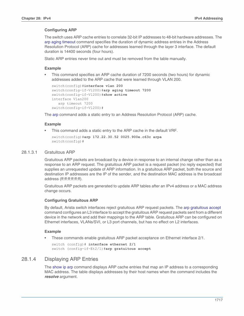
Configuring ARP
The switch uses ARP cache entries to correlate 32-bit IP addresses to 48-bit hardware addresses. Thearp aging timeout command specifies the duration of dynamic address entries in the AddressResolution Protocol (ARP) cache for addresses learned through the layer 3 interface. The defaultduration is 14400 seconds (four hours).
Static ARP entries never time out and must be removed from the table manually.
Example
• This command specifies an ARP cache duration of 7200 seconds (two hours) for dynamicaddresses added to the ARP cache that were learned through VLAN 200.
switch(config)#interface vlan 200switch(config-if-Vl200)#arp aging timeout 7200switch(config-if-Vl200)#show activeinterface Vlan200 arp timeout 7200switch(config-if-Vl200)#
The arp command adds a static entry to an Address Resolution Protocol (ARP) cache.
Example
• This command adds a static entry to the ARP cache in the default VRF.
switch(config)#arp 172.22.30.52 0025.900e.c63c arpaswitch(config)#
28.1.3.1 Gratuitous ARP
Gratuitous ARP packets are broadcast by a device in response to an internal change rather than as aresponse to an ARP request. The gratuitous ARP packet is a request packet (no reply expected) thatsupplies an unrequested update of ARP information. In a gratuitous ARP packet, both the source anddestination IP addresses are the IP of the sender, and the destination MAC address is the broadcastaddress (ff:ff:ff:ff:ff:ff).
Gratuitous ARP packets are generated to update ARP tables after an IPv4 address or a MAC addresschange occurs.
Configuring Gratuitous ARP
By default, Arista switch interfaces reject gratuitous ARP request packets. The arp gratuitous acceptcommand configures an L3 interface to accept the gratuitous ARP request packets sent from a differentdevice in the network and add their mappings to the ARP table. Gratuitous ARP can be configured onEthernet interfaces, VLANs/SVI, or L3 port channels, but has no effect on L2 interfaces.
Example
• These commands enable gratuitous ARP packet acceptance on Ethernet interface 2/1.
switch (config)# interface ethernet 2/1switch (config-if-Et2/1)#arp gratuitous accept
28.1.4 Displaying ARP Entries
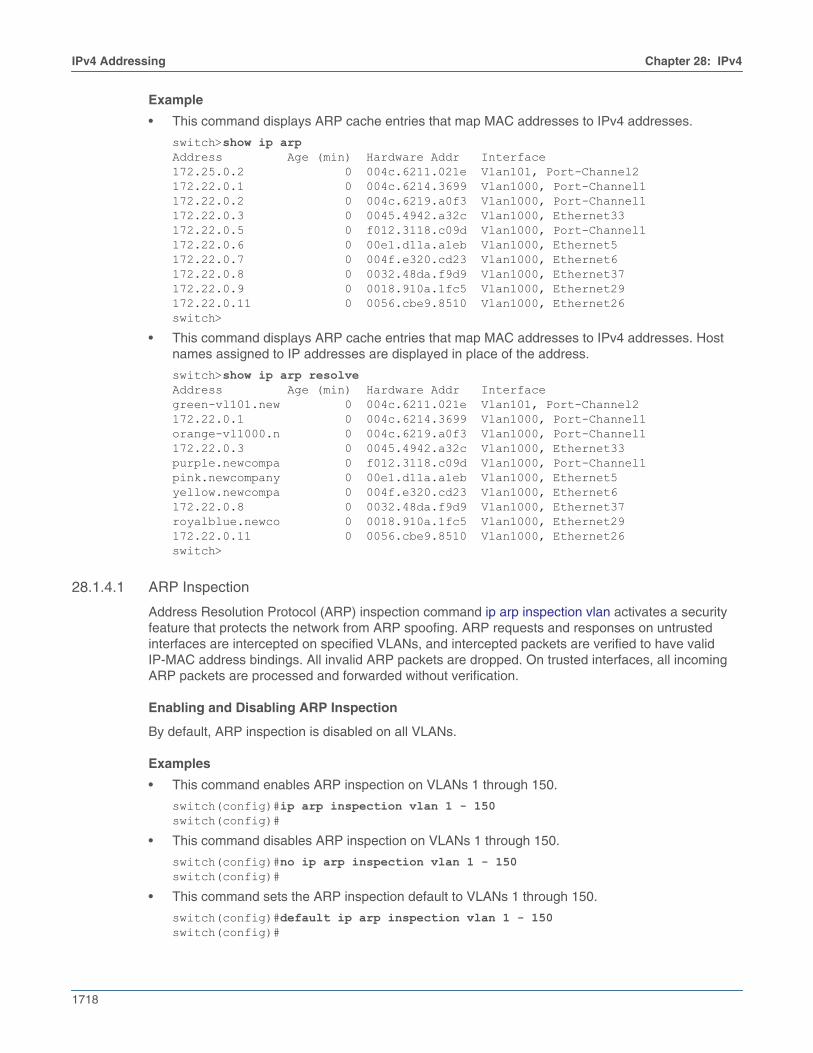
The show ip arp command displays ARP cache entries that map an IP address to a correspondingMAC address. The table displays addresses by their host names when the command includes theresolve argument.
1718
IPv4 Addressing Chapter 28: IPv4
Example
• This command displays ARP cache entries that map MAC addresses to IPv4 addresses.
switch>show ip arpAddress Age (min) Hardware Addr Interface172.25.0.2 0 004c.6211.021e Vlan101, Port-Channel2172.22.0.1 0 004c.6214.3699 Vlan1000, Port-Channel1172.22.0.2 0 004c.6219.a0f3 Vlan1000, Port-Channel1172.22.0.3 0 0045.4942.a32c Vlan1000, Ethernet33172.22.0.5 0 f012.3118.c09d Vlan1000, Port-Channel1172.22.0.6 0 00e1.d11a.a1eb Vlan1000, Ethernet5172.22.0.7 0 004f.e320.cd23 Vlan1000, Ethernet6172.22.0.8 0 0032.48da.f9d9 Vlan1000, Ethernet37172.22.0.9 0 0018.910a.1fc5 Vlan1000, Ethernet29172.22.0.11 0 0056.cbe9.8510 Vlan1000, Ethernet26switch>
• This command displays ARP cache entries that map MAC addresses to IPv4 addresses. Hostnames assigned to IP addresses are displayed in place of the address.
switch>show ip arp resolveAddress Age (min) Hardware Addr Interfacegreen-vl101.new 0 004c.6211.021e Vlan101, Port-Channel2172.22.0.1 0 004c.6214.3699 Vlan1000, Port-Channel1orange-vl1000.n 0 004c.6219.a0f3 Vlan1000, Port-Channel1172.22.0.3 0 0045.4942.a32c Vlan1000, Ethernet33purple.newcompa 0 f012.3118.c09d Vlan1000, Port-Channel1pink.newcompany 0 00e1.d11a.a1eb Vlan1000, Ethernet5yellow.newcompa 0 004f.e320.cd23 Vlan1000, Ethernet6172.22.0.8 0 0032.48da.f9d9 Vlan1000, Ethernet37royalblue.newco 0 0018.910a.1fc5 Vlan1000, Ethernet29172.22.0.11 0 0056.cbe9.8510 Vlan1000, Ethernet26switch>
28.1.4.1 ARP Inspection
Address Resolution Protocol (ARP) inspection command ip arp inspection vlan activates a securityfeature that protects the network from ARP spoofing. ARP requests and responses on untrustedinterfaces are intercepted on specified VLANs, and intercepted packets are verified to have validIP-MAC address bindings. All invalid ARP packets are dropped. On trusted interfaces, all incomingARP packets are processed and forwarded without verification.
Enabling and Disabling ARP Inspection
By default, ARP inspection is disabled on all VLANs.
Examples
• This command enables ARP inspection on VLANs 1 through 150.
switch(config)#ip arp inspection vlan 1 - 150switch(config)#
• This command disables ARP inspection on VLANs 1 through 150.
switch(config)#no ip arp inspection vlan 1 - 150switch(config)#
• This command sets the ARP inspection default to VLANs 1 through 150.
switch(config)#default ip arp inspection vlan 1 - 150switch(config)#
Chapter 28: IPv4 IPv4 Addressing
1719
• These commands enable ARP inspection on multiple VLANs 1 through 150 and 200 through 250.
switch(config)#ip arp inspection vlan 1-150,200-250switch(config)#
Syslog for Invalid ARP Packets Dropped
When an invalid ARP packet is dropped, the following syslog message appears. The log severity levelcan be set higher if required.
%SECURITY-4-ARP_PACKET_DROPPED: Dropped ARP packet on interface Ethernet28/1 Vlan 2121 because invalid mac and ip binding. Received: 00:0a:00:bc:00:de/1.1.1.1.
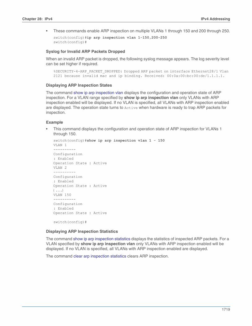
Displaying ARP Inspection States
The command show ip arp inspection vlan displays the configuration and operation state of ARPinspection. For a VLAN range specified by show ip arp inspection vlan only VLANs with ARPinspection enabled will be displayed. If no VLAN is specified, all VLANs with ARP inspection enabledare displayed. The operation state turns to Active when hardware is ready to trap ARP packets forinspection.
Example
• This command displays the configuration and operation state of ARP inspection for VLANs 1through 150.
switch(config)#show ip arp inspection vlan 1 - 150VLAN 1----------Configuration: EnabledOperation State : ActiveVLAN 2----------Configuration: EnabledOperation State : Active{...}VLAN 150----------Configuration: EnabledOperation State : Active
switch(config)#
Displaying ARP Inspection Statistics
The command show ip arp inspection statistics displays the statistics of inspected ARP packets. For aVLAN specified by show ip arp inspection vlan only VLANs with ARP inspection enabled will bedisplayed. If no VLAN is specified, all VLANs with ARP inspection enabled are displayed.
The command clear arp inspection statistics clears ARP inspection.
1720
IPv4 Addressing Chapter 28: IPv4
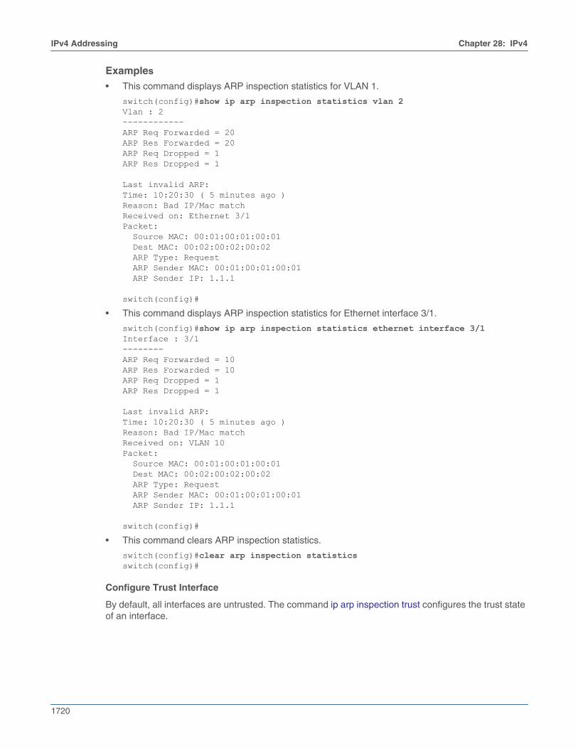
Examples
• This command displays ARP inspection statistics for VLAN 1.
switch(config)#show ip arp inspection statistics vlan 2Vlan : 2------------ARP Req Forwarded = 20ARP Res Forwarded = 20ARP Req Dropped = 1ARP Res Dropped = 1
Last invalid ARP:Time: 10:20:30 ( 5 minutes ago )Reason: Bad IP/Mac matchReceived on: Ethernet 3/1Packet: Source MAC: 00:01:00:01:00:01 Dest MAC: 00:02:00:02:00:02 ARP Type: Request ARP Sender MAC: 00:01:00:01:00:01 ARP Sender IP: 1.1.1
switch(config)#
• This command displays ARP inspection statistics for Ethernet interface 3/1.
switch(config)#show ip arp inspection statistics ethernet interface 3/1Interface : 3/1--------ARP Req Forwarded = 10ARP Res Forwarded = 10ARP Req Dropped = 1ARP Res Dropped = 1
Last invalid ARP:Time: 10:20:30 ( 5 minutes ago )Reason: Bad IP/Mac matchReceived on: VLAN 10Packet: Source MAC: 00:01:00:01:00:01 Dest MAC: 00:02:00:02:00:02 ARP Type: Request ARP Sender MAC: 00:01:00:01:00:01 ARP Sender IP: 1.1.1
switch(config)#
• This command clears ARP inspection statistics.
switch(config)#clear arp inspection statisticsswitch(config)#
Configure Trust Interface
By default, all interfaces are untrusted. The command ip arp inspection trust configures the trust stateof an interface.
Chapter 28: IPv4 IPv4 Addressing
1721
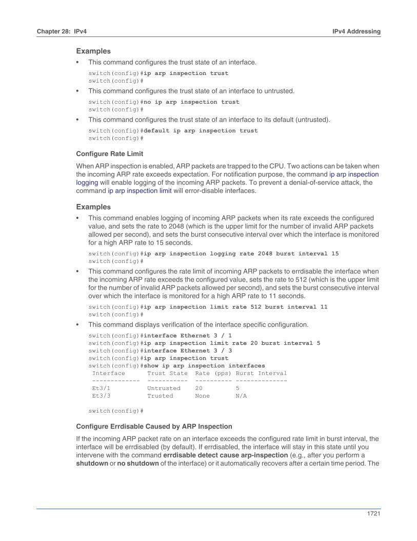
Examples
• This command configures the trust state of an interface.
switch(config)#ip arp inspection trustswitch(config)#
• This command configures the trust state of an interface to untrusted.
switch(config)#no ip arp inspection trustswitch(config)#
• This command configures the trust state of an interface to its default (untrusted).
switch(config)#default ip arp inspection trustswitch(config)#
Configure Rate Limit
When ARP inspection is enabled, ARP packets are trapped to the CPU. Two actions can be taken whenthe incoming ARP rate exceeds expectation. For notification purpose, the command ip arp inspectionlogging will enable logging of the incoming ARP packets. To prevent a denial-of-service attack, thecommand ip arp inspection limit will error-disable interfaces.
Examples
• This command enables logging of incoming ARP packets when its rate exceeds the configuredvalue, and sets the rate to 2048 (which is the upper limit for the number of invalid ARP packetsallowed per second), and sets the burst consecutive interval over which the interface is monitoredfor a high ARP rate to 15 seconds.
switch(config)#ip arp inspection logging rate 2048 burst interval 15switch(config)#
• This command configures the rate limit of incoming ARP packets to errdisable the interface whenthe incoming ARP rate exceeds the configured value, sets the rate to 512 (which is the upper limitfor the number of invalid ARP packets allowed per second), and sets the burst consecutive intervalover which the interface is monitored for a high ARP rate to 11 seconds.
switch(config)#ip arp inspection limit rate 512 burst interval 11switch(config)#
• This command displays verification of the interface specific configuration.
switch(config)#interface Ethernet 3 / 1switch(config)#ip arp inspection limit rate 20 burst interval 5switch(config)#interface Ethernet 3 / 3switch(config)#ip arp inspection trustswitch(config)#show ip arp inspection interfaces Interface Trust State Rate (pps) Burst Interval ------------- ----------- ---------- -------------- Et3/1 Untrusted 20 5 Et3/3 Trusted None N/A
switch(config)#
Configure Errdisable Caused by ARP Inspection
If the incoming ARP packet rate on an interface exceeds the configured rate limit in burst interval, theinterface will be errdisabled (by default). If errdisabled, the interface will stay in this state until youintervene with the command errdisable detect cause arp-inspection (e.g., after you perform ashutdown or no shutdown of the interface) or it automatically recovers after a certain time period. The
1722
IPv4 Addressing Chapter 28: IPv4
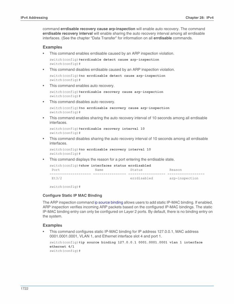
command errdisable recovery cause arp-inspection will enable auto recovery. The commanderrdisable recovery interval will enable sharing the auto recovery interval among all errdisableinterfaces. (See the chapter “Data Transfer” for information on all errdisable commands.
Examples
• This command enables errdisable caused by an ARP inspection violation.
switch(config)#errdisable detect cause arp-inspectionswitch(config)#
• This command disables errdisable caused by an ARP inspection violation.
switch(config)#no errdisable detect cause arp-inspectionswitch(config)#
• This command enables auto recovery.
switch(config)#errdisable recovery cause arp-inspectionswitch(config)#
• This command disables auto recovery.
switch(config)#no errdisable recovery cause arp-inspectionswitch(config)#
• This command enables sharing the auto recovery interval of 10 seconds among all errdisableinterfaces.
switch(config)#errdisable recovery interval 10switch(config)#
• This command disables sharing the auto recovery interval of 10 seconds among all errdisableinterfaces.
switch(config)#no errdisable recovery interval 10switch(config)#
• This command displays the reason for a port entering the errdisable state.
switch(config)#show interfaces status errdisabled Port Name Status Reason-------------------- ---------------- ------------------ ------------------ Et3/2 errdisabled arp-inspection
switch(config)#
Configure Static IP MAC Binding
The ARP inspection command ip source binding allows users to add static IP-MAC binding. If enabled,ARP inspection verifies incoming ARP packets based on the configured IP-MAC bindings. The staticIP-MAC binding entry can only be configured on Layer 2 ports. By default, there is no binding entry onthe system.
Examples
• This command configures static IP-MAC binding for IP address 127.0.0.1, MAC address0001.0001.0001, VLAN 1, and Ethernet interface slot 4 and port 1.
switch(config)#ip source binding 127.0.0.1 0001.0001.0001 vlan 1 interface ethernet 4/1switch(config)#
Chapter 28: IPv4 IPv4 Addressing
1723
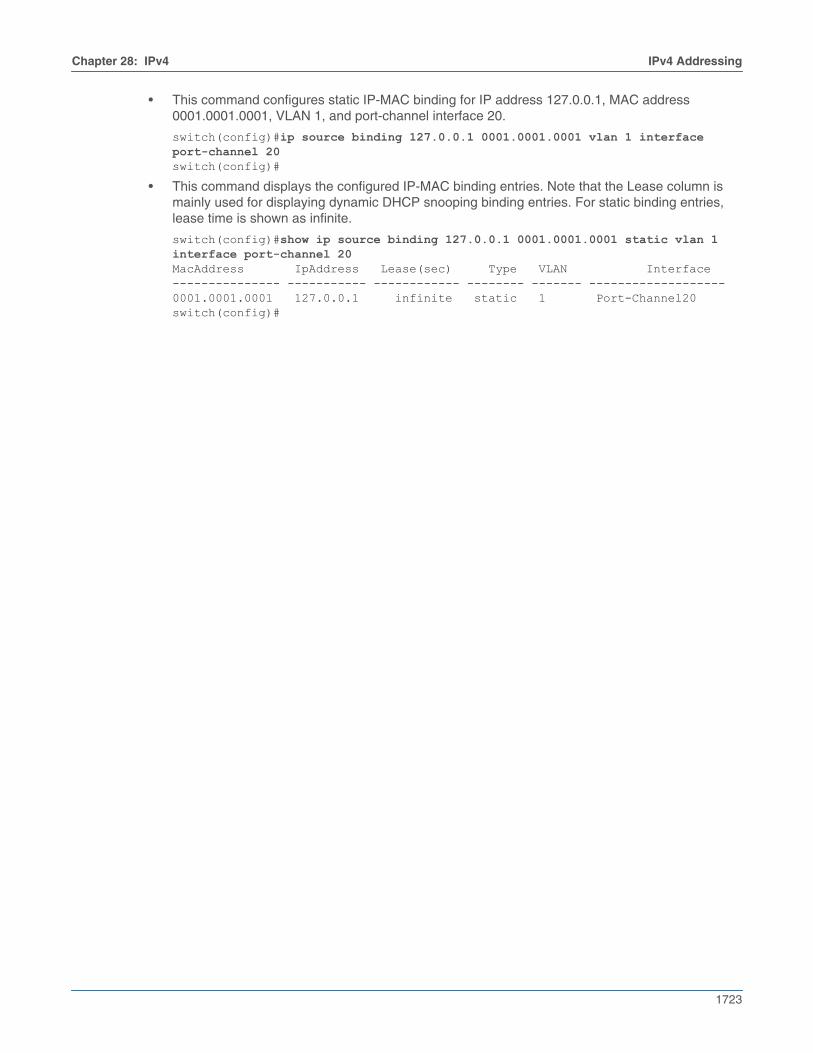
• This command configures static IP-MAC binding for IP address 127.0.0.1, MAC address0001.0001.0001, VLAN 1, and port-channel interface 20.
switch(config)#ip source binding 127.0.0.1 0001.0001.0001 vlan 1 interface port-channel 20switch(config)#
• This command displays the configured IP-MAC binding entries. Note that the Lease column ismainly used for displaying dynamic DHCP snooping binding entries. For static binding entries,lease time is shown as infinite.
switch(config)#show ip source binding 127.0.0.1 0001.0001.0001 static vlan 1 interface port-channel 20MacAddress IpAddress Lease(sec) Type VLAN Interface--------------- ----------- ------------ -------- ------- -------------------0001.0001.0001 127.0.0.1 infinite static 1 Port-Channel20switch(config)#

1724
IPv4 Routing Chapter 28: IPv4
28.2 IPv4 RoutingInternet Protocol version 4 (IPv4) is a communications protocol used for relaying network packetsacross a set of connected networks using the Internet Protocol suite. Routing transmits network layerdata packets over connected independent subnets. Each subnet is assigned an IP address range andeach device on the subnet is assigned an IP address from that range. The connected subnets have IPaddress ranges that do not overlap.
A router is a network device that connects multiple subnets. Routers forward inbound packets to thesubnet whose address range includes the packets’ destination address. IPv4 and IPv6 are internetlayer protocols that define packet-switched internetworking, including source-to-destination datagramtransmission across multiple networks.
These sections describe IPv4 routing and route creation options:
• Section 28.2.1: Enabling IPv4 Routing
• Section 28.2.2: Static and Default IPv4 Routes
• Section 28.2.3: Dynamic IPv4 Routes
• Section 28.2.4: Viewing IPv4 Routes and Network Components
28.2.1 Enabling IPv4 Routing
When IPv4 routing is enabled, the switch attempts to deliver inbound packets to destination IPv4addresses by forwarding them to interfaces or next hop addresses specified by the forwarding table.
The ip routing command enables IPv4 routing.
Example
• This command enables IP routing:
switch(config)#ip routingswitch(config)#
28.2.2 Static and Default IPv4 Routes
Static routes are entered through the CLI and are typically used when dynamic protocols are unable toestablish routes to a specified destination prefix. Static routes are also useful when dynamic routingprotocols are not available or appropriate. Creating a static route associates a destination IP addresswith a local interface. The routing table refers to these routes as connected routes that are availablefor redistribution into routing domains defined by dynamic routing protocols.
The ip route command creates a static route. The destination is a network segment; the nexthop iseither an IP address or a routable interface port. When multiple routes exist to a destination prefix, theroute with the lowest administrative distance takes precedence.
By default, the administrative distance assigned to static routes is 1. Assigning a higher administrativedistance to a static route configures it to be overridden by dynamic routing data. For example, a staticroute with a distance value of 200 is overridden by OSPF intra-area routes, which have a defaultdistance of 110.
A route tag is a 32-bit number that is attached to a route. Route maps use tags to filter routes. Staticroutes have a default tag value of 0.
Example
• This command creates a static route:
switch(config)#ip route 172.17.252.0/24 vlan 500switch(config)#
Chapter 28: IPv4 IPv4 Routing
1725
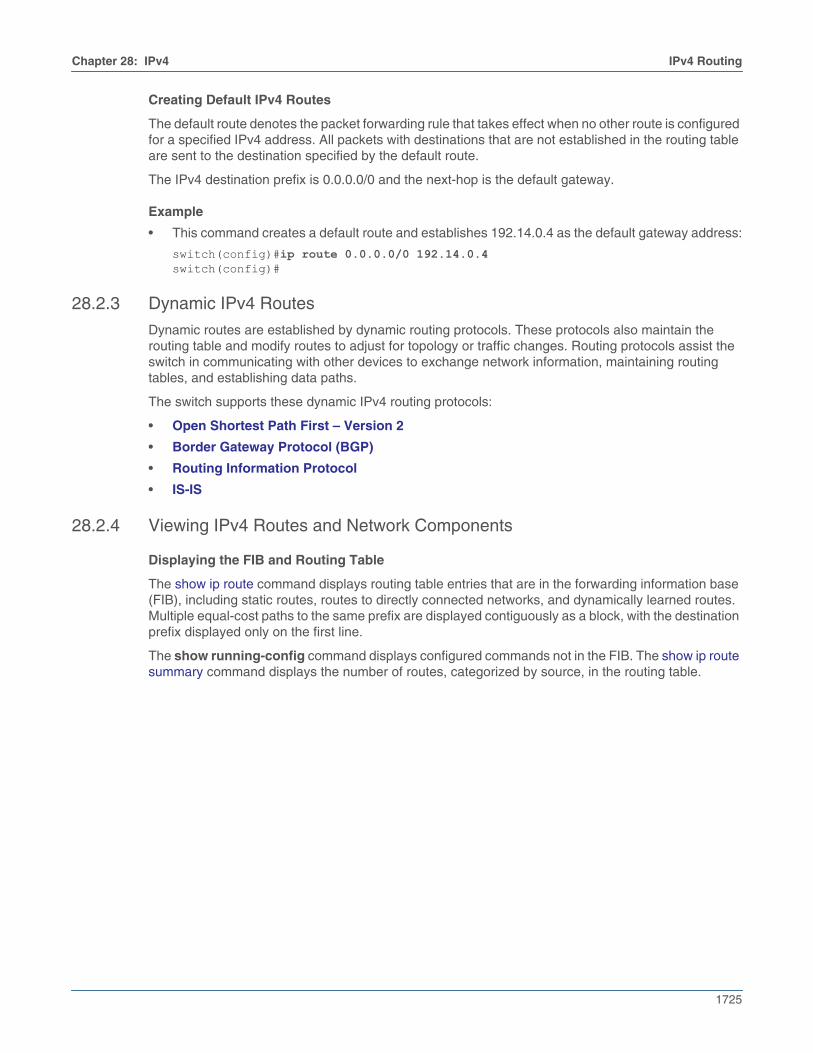
Creating Default IPv4 Routes
The default route denotes the packet forwarding rule that takes effect when no other route is configuredfor a specified IPv4 address. All packets with destinations that are not established in the routing tableare sent to the destination specified by the default route.
The IPv4 destination prefix is 0.0.0.0/0 and the next-hop is the default gateway.
Example
• This command creates a default route and establishes 192.14.0.4 as the default gateway address:
switch(config)#ip route 0.0.0.0/0 192.14.0.4switch(config)#
28.2.3 Dynamic IPv4 Routes
Dynamic routes are established by dynamic routing protocols. These protocols also maintain therouting table and modify routes to adjust for topology or traffic changes. Routing protocols assist theswitch in communicating with other devices to exchange network information, maintaining routingtables, and establishing data paths.
The switch supports these dynamic IPv4 routing protocols:
• Open Shortest Path First – Version 2
• Border Gateway Protocol (BGP)
• Routing Information Protocol
• IS-IS
28.2.4 Viewing IPv4 Routes and Network Components
Displaying the FIB and Routing Table
The show ip route command displays routing table entries that are in the forwarding information base(FIB), including static routes, routes to directly connected networks, and dynamically learned routes.Multiple equal-cost paths to the same prefix are displayed contiguously as a block, with the destinationprefix displayed only on the first line.
The show running-config command displays configured commands not in the FIB. The show ip routesummary command displays the number of routes, categorized by source, in the routing table.
1726
IPv4 Routing Chapter 28: IPv4
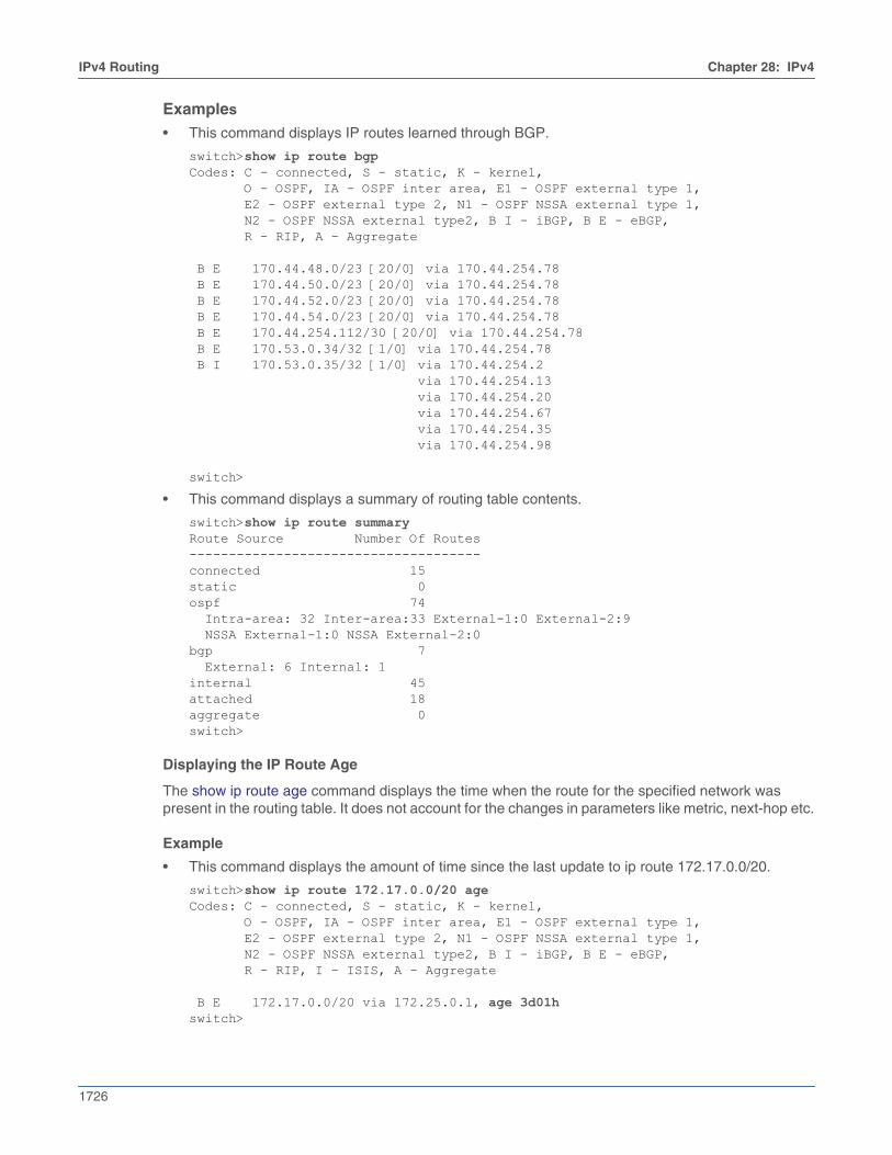
Examples
• This command displays IP routes learned through BGP.
switch>show ip route bgpCodes: C - connected, S - static, K - kernel, O - OSPF, IA - OSPF inter area, E1 - OSPF external type 1, E2 - OSPF external type 2, N1 - OSPF NSSA external type 1, N2 - OSPF NSSA external type2, B I - iBGP, B E - eBGP, R - RIP, A - Aggregate
B E 170.44.48.0/23 [20/0] via 170.44.254.78 B E 170.44.50.0/23 [20/0] via 170.44.254.78 B E 170.44.52.0/23 [20/0] via 170.44.254.78 B E 170.44.54.0/23 [20/0] via 170.44.254.78 B E 170.44.254.112/30 [20/0] via 170.44.254.78 B E 170.53.0.34/32 [1/0] via 170.44.254.78 B I 170.53.0.35/32 [1/0] via 170.44.254.2 via 170.44.254.13 via 170.44.254.20 via 170.44.254.67 via 170.44.254.35 via 170.44.254.98
switch>
• This command displays a summary of routing table contents.
switch>show ip route summaryRoute Source Number Of Routes-------------------------------------connected 15static 0ospf 74 Intra-area: 32 Inter-area:33 External-1:0 External-2:9 NSSA External-1:0 NSSA External-2:0bgp 7 External: 6 Internal: 1internal 45attached 18aggregate 0switch>
Displaying the IP Route Age
The show ip route age command displays the time when the route for the specified network waspresent in the routing table. It does not account for the changes in parameters like metric, next-hop etc.
Example
• This command displays the amount of time since the last update to ip route 172.17.0.0/20.
switch>show ip route 172.17.0.0/20 ageCodes: C - connected, S - static, K - kernel, O - OSPF, IA - OSPF inter area, E1 - OSPF external type 1, E2 - OSPF external type 2, N1 - OSPF NSSA external type 1, N2 - OSPF NSSA external type2, B I - iBGP, B E - eBGP, R - RIP, I - ISIS, A - Aggregate
B E 172.17.0.0/20 via 172.25.0.1, age 3d01hswitch>
Chapter 28: IPv4 IPv4 Routing
1727
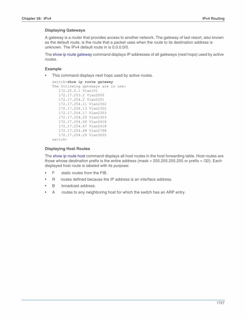
Displaying Gateways
A gateway is a router that provides access to another network. The gateway of last resort, also knownas the default route, is the route that a packet uses when the route to its destination address isunknown. The IPv4 default route in is 0.0.0.0/0.
The show ip route gateway command displays IP addresses of all gateways (next hops) used by activeroutes.
Example
• This command displays next hops used by active routes.
switch>show ip route gatewayThe following gateways are in use: 172.25.0.1 Vlan101 172.17.253.2 Vlan2000 172.17.254.2 Vlan2201 172.17.254.11 Vlan2302 172.17.254.13 Vlan2302 172.17.254.17 Vlan2303 172.17.254.20 Vlan2303 172.17.254.66 Vlan2418 172.17.254.67 Vlan2418 172.17.254.68 Vlan2768 172.17.254.29 Vlan3020switch>
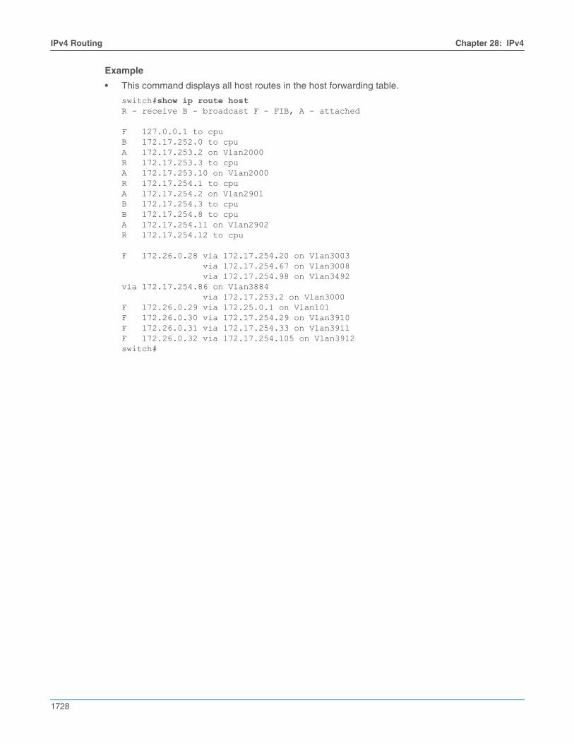
Displaying Host Routes
The show ip route host command displays all host routes in the host forwarding table. Host routes arethose whose destination prefix is the entire address (mask = 255.255.255.255 or prefix = /32). Eachdisplayed host route is labeled with its purpose:
• F static routes from the FIB.
• R routes defined because the IP address is an interface address.
• B broadcast address.
• A routes to any neighboring host for which the switch has an ARP entry.
1728
IPv4 Routing Chapter 28: IPv4
Example
• This command displays all host routes in the host forwarding table.
switch#show ip route hostR - receive B - broadcast F - FIB, A - attached
F 127.0.0.1 to cpuB 172.17.252.0 to cpuA 172.17.253.2 on Vlan2000R 172.17.253.3 to cpuA 172.17.253.10 on Vlan2000R 172.17.254.1 to cpuA 172.17.254.2 on Vlan2901B 172.17.254.3 to cpuB 172.17.254.8 to cpuA 172.17.254.11 on Vlan2902R 172.17.254.12 to cpu
F 172.26.0.28 via 172.17.254.20 on Vlan3003 via 172.17.254.67 on Vlan3008 via 172.17.254.98 on Vlan3492via 172.17.254.86 on Vlan3884 via 172.17.253.2 on Vlan3000F 172.26.0.29 via 172.25.0.1 on Vlan101F 172.26.0.30 via 172.17.254.29 on Vlan3910F 172.26.0.31 via 172.17.254.33 on Vlan3911F 172.26.0.32 via 172.17.254.105 on Vlan3912switch#
Chapter 28: IPv4 IPv4 Multicast Counters
1729
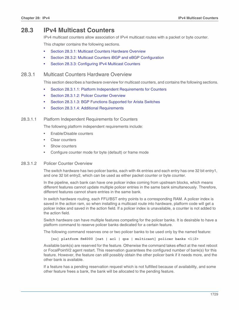
28.3 IPv4 Multicast CountersIPv4 multicast counters allow association of IPv4 multicast routes with a packet or byte counter.
This chapter contains the following sections.
• Section 28.3.1: Multicast Counters Hardware Overview
• Section 28.3.2: Multicast Counters iBGP and eBGP Configuration
• Section 28.3.3: Configuring IPv4 Multicast Counters
28.3.1 Multicast Counters Hardware Overview
This section describes a hardware overview for multicast counters, and contains the following sections.
• Section 28.3.1.1: Platform Independent Requirements for Counters
• Section 28.3.1.2: Policer Counter Overview
• Section 28.3.1.3: BGP Functions Supported for Arista Switches
• Section 28.3.1.4: Additional Requirements
28.3.1.1 Platform Independent Requirements for Counters
The following platform independent requirements include:
• Enable/Disable counters
• Clear counters
• Show counters
• Configure counter mode for byte (default) or frame mode
28.3.1.2 Policer Counter Overview
The switch hardware has two policer banks, each with 4k entries and each entry has one 32 bit entry1,and one 32 bit entry2, which can be used as either packet counter or byte counter.
In the pipeline, each bank can have one policer index coming from upstream blocks, which meansdifferent features cannot update multiple policer entries in the same bank simultaneously. Therefore,different features cannot share entries in the same bank.
In switch hardware routing, each FFU/BST entry points to a corresponding RAM. A policer index issaved in the action ram, so when installing a multicast route into hardware, platform code will get apolicer index and saved in the action field. If a policer index is unavailable, a counter is not added tothe action field.
Switch hardware can have multiple features competing for the policer banks. It is desirable to have aplatform command to reserve policer banks dedicated for a certain feature.
The following command reserves one or two policer banks to be used only by the named feature:
[no] platform fm6000 [nat | acl | qos | multicast] policer banks <1|2>
Available bank(s) are reserved for the feature. Otherwise the command takes effect at the next rebootor FocalPointV2 agent restart. This reservation guarantees the configured number of bank(s) for thisfeature. However, the feature can still possibly obtain the other policer bank if it needs more, and theother bank is available.
If a feature has a pending reservation request which is not fulfilled because of availability, and someother feature frees a bank, the bank will be allocated to the pending feature.
1730
IPv4 Multicast Counters Chapter 28: IPv4
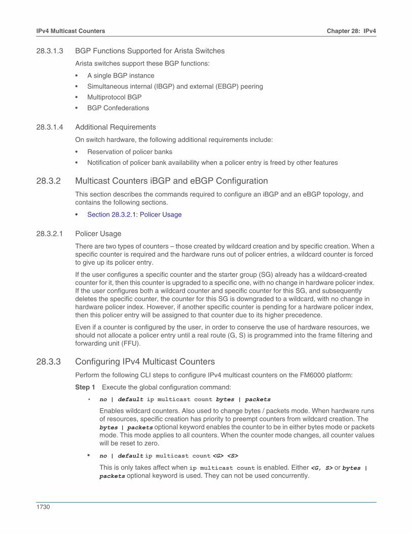
28.3.1.3 BGP Functions Supported for Arista Switches
Arista switches support these BGP functions:
• A single BGP instance
• Simultaneous internal (IBGP) and external (EBGP) peering
• Multiprotocol BGP
• BGP Confederations
28.3.1.4 Additional Requirements
On switch hardware, the following additional requirements include:
• Reservation of policer banks
• Notification of policer bank availability when a policer entry is freed by other features
28.3.2 Multicast Counters iBGP and eBGP Configuration
This section describes the commands required to configure an iBGP and an eBGP topology, andcontains the following sections.
• Section 28.3.2.1: Policer Usage
28.3.2.1 Policer Usage
There are two types of counters – those created by wildcard creation and by specific creation. When aspecific counter is required and the hardware runs out of policer entries, a wildcard counter is forcedto give up its policer entry.
If the user configures a specific counter and the starter group (SG) already has a wildcard-createdcounter for it, then this counter is upgraded to a specific one, with no change in hardware policer index.If the user configures both a wildcard counter and specific counter for this SG, and subsequentlydeletes the specific counter, the counter for this SG is downgraded to a wildcard, with no change inhardware policer index. However, if another specific counter is pending for a hardware policer index,then this policer entry will be assigned to that counter due to its higher precedence.
Even if a counter is configured by the user, in order to conserve the use of hardware resources, weshould not allocate a policer entry until a real route (G, S) is programmed into the frame filtering andforwarding unit (FFU).
28.3.3 Configuring IPv4 Multicast Counters
Perform the following CLI steps to configure IPv4 multicast counters on the FM6000 platform:
Step 1 Execute the global configuration command:
• no | default ip multicast count bytes | packets
Enables wildcard counters. Also used to change bytes / packets mode. When hardware runsof resources, specific creation has priority to preempt counters from wildcard creation. Thebytes | packets optional keyword enables the counter to be in either bytes mode or packetsmode. This mode applies to all counters. When the counter mode changes, all counter valueswill be reset to zero.
• no | default ip multicast count <G> <S>
This is only takes affect when ip multicast count is enabled. Either <G, S> or bytes | packets optional keyword is used. They can not be used concurrently.
Chapter 28: IPv4 IPv4 Multicast Counters
1731
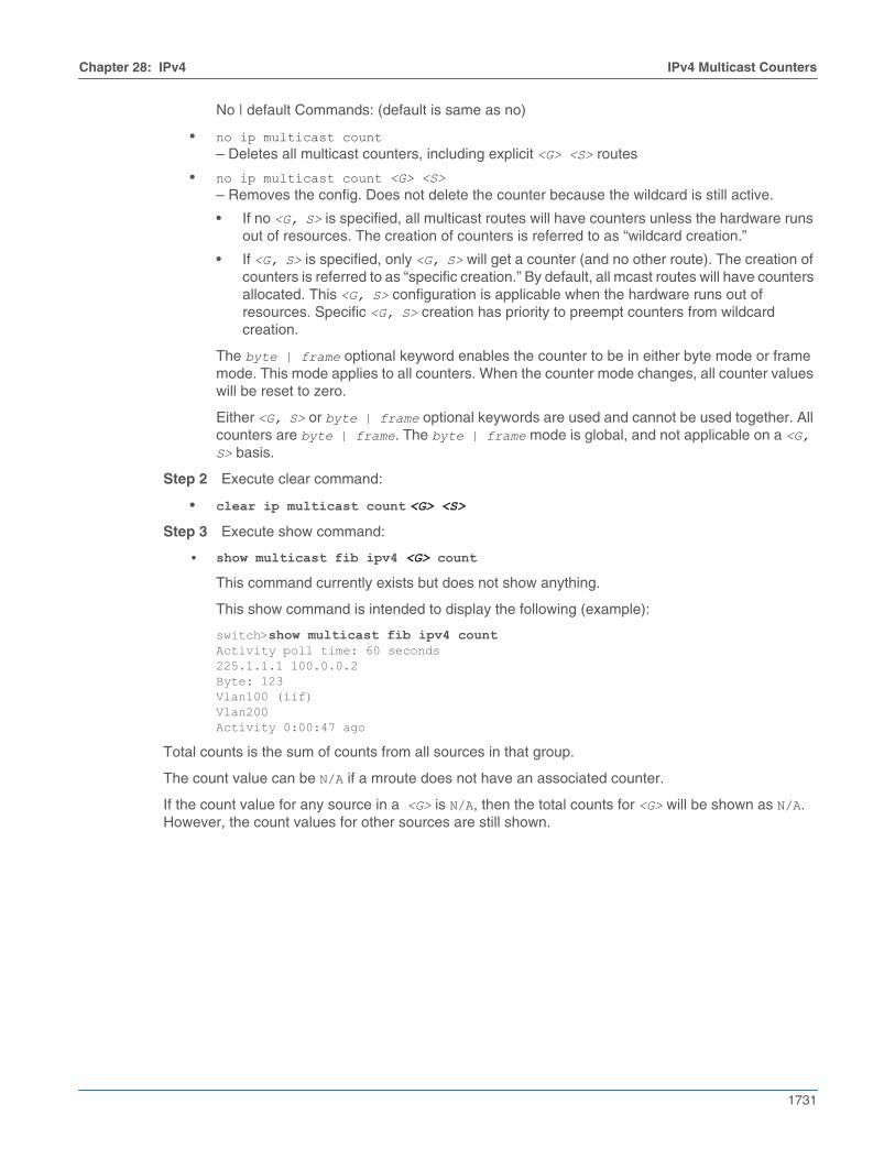
No | default Commands: (default is same as no)
• no ip multicast count– Deletes all multicast counters, including explicit <G> <S> routes
• no ip multicast count <G> <S>– Removes the config. Does not delete the counter because the wildcard is still active.
• If no <G, S> is specified, all multicast routes will have counters unless the hardware runsout of resources. The creation of counters is referred to as “wildcard creation.”
• If <G, S> is specified, only <G, S> will get a counter (and no other route). The creation ofcounters is referred to as “specific creation.” By default, all mcast routes will have countersallocated. This <G, S> configuration is applicable when the hardware runs out ofresources. Specific <G, S> creation has priority to preempt counters from wildcardcreation.
The byte | frame optional keyword enables the counter to be in either byte mode or framemode. This mode applies to all counters. When the counter mode changes, all counter valueswill be reset to zero.
Either <G, S> or byte | frame optional keywords are used and cannot be used together. Allcounters are byte | frame. The byte | frame mode is global, and not applicable on a <G, S> basis.
Step 2 Execute clear command:
• clear ip multicast count <G> <S>
Step 3 Execute show command:
• show multicast fib ipv4 <G> count
This command currently exists but does not show anything.
This show command is intended to display the following (example):
switch>show multicast fib ipv4 countActivity poll time: 60 seconds225.1.1.1 100.0.0.2Byte: 123Vlan100 (iif)Vlan200Activity 0:00:47 ago
Total counts is the sum of counts from all sources in that group.
The count value can be N/A if a mroute does not have an associated counter.
If the count value for any source in a <G> is N/A, then the total counts for <G> will be shown as N/A.However, the count values for other sources are still shown.
1732
Route Management Chapter 28: IPv4
28.4 Route ManagementWhen routing is enabled, the switch discovers the best route to a packet’s destination address byexchanging routing information with other devices. IP routing is disabled by default.
The following sections describes routing features that the switch supports
• Section 28.4.1: Route Redistribution
• Section 28.4.2: Equal Cost Multipath Routing (ECMP) and Load Sharing
• Section 28.4.3: Unicast Reverse Path Forwarding (uRPF)
• Section 28.4.4: Routing Tables / Virtual Routing and Forwarding (VRF)
• Section 28.4.5: RIB Route Control
28.4.1 Route Redistribution
Route redistribution is the advertisement, into a dynamic routing protocol’s routing domain, ofconnected (static) routes or routes established by other routing protocols. By default, the switchadvertises only routes in a routing domain that are established by the protocol that defined the domain.
Route redistribution commands specify the scope of the redistribution action. By default, all routes froma specified protocol (or all static routes) are advertised into the routing domain. Commands can alsofilter routes by applying a route map, which defines the subset of routes to be advertised.
28.4.2 Equal Cost Multipath Routing (ECMP) and Load Sharing
Equal cost multi-path (ECMP) is a routing strategy where traffic is forwarded over multiple paths thathave equal routing metric values.
Configuring ECMP (IPv4)
All ECMP paths are assigned the same tag value; commands that change the tag value of a path alsochange the tag value of all paths in the ECMP route.
In a network topology using ECMP routing, hash polarization may result when all switches performidentical hash calculations. Hash polarization leads to uneven load distribution among the data paths.Hash polarization is avoided when switches use different hash seeds to perform hash calculations.
The ip load-sharing command provides the hash seed to an algorithm that the switch uses to distributedata streams among multiple equal-cost routes to a specified subnet.
Example
• This command sets the IPv4 load sharing hash seed to 20:
switch(config)#ip load-sharing fm6000 20switch(config)#
Multicast Traffic Over ECMP
The switch attempts to spread outbound unicast and multicast traffic to all ECMP route paths equally.To disable the sending of multicast traffic over ECMP, use the multipath none command or the nomultipath deterministic command.
Resilient ECMP
Resilient ECMP is used for those prefixes where it is not desirable for routes to be rehashed due to linkflap, typically where ECMP is being used for load balancing. Resilient ECMP configures a fixed numberof next-hop entries in the hardware ECMP table for all the routes within a specified IP address prefix.
Chapter 28: IPv4 Route Management
1733
Implementing fixed table entries for a specified next-hop address allows data flows that are hashed toa valid next-hop number to remain intact even when some of the next hops go down or come backonline.
Resilient ECMP is enabled for all routes within a specified prefix using the ip hardware fib ecmpresilience command. The command specifies the maximum number of next-hop addresses that thehardware ECMP table can contain for the specified IP prefix, and configures a redundancy factor thatfacilitates the duplication of next-hop addresses in the table. The fixed table space for the address isthe maximum number of next hops multiplied by the redundancy factor. When the table contains themaximum number of next-hop addresses, the redundancy factor specifies the number of times eachaddress is listed in the table. When the table contains fewer than the maximum number of next-hopaddresses, the table space entries are filled by additional duplication of the nexthop addresses.
Resilient ECMP is also available for IPv6 IP addresses.
Example
• This command configures a hardware ECMP table space of 24 entries for the IP address10.14.2.2/24. A maximum of six next-hop addresses can be specified for the IP address. When thetable contains six next-hop addresses, each appears in the table four times. When the tablecontains fewer than six next-hop addresses, each is duplicated until the 24 table entries are filled.
switch(config)#ip hardware fib ecmp resilience 10.14.2.2/24 capacity 6 redundancy 4switch(config)#
28.4.3 Unicast Reverse Path Forwarding (uRPF)
Unicast Reverse Path Forwarding (uRPF) verifies the accessibility of source IP addresses in packetsthat the switch forwards. The switch drops a packet when uRPF determines that the routing table doesnot contain an entry with a valid path to that packet’s source IP address.
IPv4 and IPv6 uRPF operate independently. uRPF is VRF aware. Commands that do not specify a VRFutilize the default instance. Multicast routing is not affected by uRPF.
uRPF defines two operational modes: strict mode and loose mode.
• Strict mode: uRPF also verifies that a packet is received on the interface that its routing table entrywill use for its return packet.
• Loose mode: uRPF validation does not consider the inbound packet’s ingress interface.
28.4.3.1 uRPF Operation
uRPF is configurable on interfaces. For packets arriving on a uRPF-enabled interfaces, the source IPaddress is verified by examining the source and destination addresses of unicast routing table entries.
uRPF requires a reconfigured routing table to support IP address verification. When uRPF is enabledfor the first time, unicast routing is briefly disabled to facilitate the routing table reconfiguration. Multicastrouting is not affected by the initial uRPF enabling.
A packet fails uRPF verification if the table does not contain an entry whose source or destinationaddress matches the packet’s source IP address. In strict mode, the uRPF also fails when the matchingentry’s outbound interface does not match the packet’s ingress interface.
uRPF verification is not available for the following packets:
• DHCP (Source is 0.0.0.0 – Destination is 255.255.255.255)
• IPv6 link local (FE80::/10)
• Multicast packets
1734
Route Management Chapter 28: IPv4
ECMP uRPF
When verifying ECMP routes, strict mode checks all possible paths to determine that a packet isreceived on the correct interface. Strict mode is supported for ECMP groups with a maximum of eightrouting table entries. The switch reverts to loose mode for ECMP groups that exceed eight entries.
Default Routes
uRPF strict mode provides an allow-default option that accepts default routes. On interfaces thatenable allow-default and a default route is defined, uRPF strict mode validates a packet even when therouting table does not contain an entry that matches the packet’s source IP address. Whenallow-default is not enabled, uRPF does not consider the default route when verifying an inboundpacket.
Null Routes
NULL0 routes drop traffic destined to a specified prefix. When uRPF is enabled, traffic originating froma null route prefixes is dropped in strict and loose modes.
28.4.3.2 uRPF Configuration
Unicast Reverse Path Forwarding (uRPF) is enabled for IPv4 packets ingressing the configurationmode interface through the ip verify command.
Note uRPF cannot be enabled on interfaces with ECMP member FECs.
Example
• This command enables uRPF loose mode on VLAN interface 17.
switch(config)#interface vlan 17switch(config-if-Vl17)#ip verify unicast source reachable-via anyswitch(config-if-Vl17)#show active interface Vlan17 ip verify unicast source reachable-via anyswitch(config-if-Vl17)#
• This command enables uRPF strict mode on VLAN interface 18.
switch(config)#interface vlan 18switch(config-if-Vl18)#ip verify unicast source reachable-via rxswitch(config-if-Vl18)#show active interface Vlan18 ip verify unicast source reachable-via rxswitch(config-if-Vl18)#
28.4.4 Routing Tables / Virtual Routing and Forwarding (VRF)
An IP routing table is a data table that lists the routes to network destinations and metrics (distances)associated with those routes. A routing table is also known as a routing information base (RIB).
Virtual Routing and Forwarding (VRF) allows traffic separation by maintaining multiple routing tables.Arista switches support multiple VRF instances: one global or default VRF called “default” and multipleuser-defined VRFs; the number of user-defined VRFs supported varies by platform. VRFs can be usedas management or data plane VRFs.
• Management VRFs have routing disabled. They are typically used for management-related traffic.
• Dataplane VRFs have routing enabled. They support routing protocols and packet forwarding(hardware and software).
Chapter 28: IPv4 Route Management
1735
Dataplane VRFs are supported by Trident, FM6000, and Arad platform switches.
VRFs support unicast IPv4 and IPv6 traffic and multicast traffic. Loopback, SVI, and routed ports maybe added to VRFs. Management ports may be added without any hardware forwarding.
To allow overlap in the sets of IP addresses used by different VRF instances, a route distinguisher (RD)may be prepended to each address. RDs are defined in RFC 4364.
28.4.4.1 Default VRF
The default VRF on Arista switches is called “default.” It is created automatically and cannot berenamed or configured. Some configuration options accept “default” as a VRF input.
28.4.4.2 User-Defined VRFs
A user-defined VRF is created with the vrf instance command. After its creation, a VRF may beassigned a route distinguisher (RD) with the rd (Router-BGP VRF and VNI Configuration Modes)command in the VRF submode of Router-BGP Configuration Mode.
Example
• These commands create a VRF named “purple,” place the switch in BGP VRF configuration modefor that VRF, and specify a route distinguisher for the VRF identifying the administrator as AS 530and assigning 12 as its local number.
switch(config)#vrf instance purpleswitch(config-vrf-purple)#router bgp 50switch(config-router-bgp)#vrf purpleswitch(config-router-bgp-vrf-purple)#rd 530:12switch(config-router-bgp-vrf-purple)#
To add interfaces to a user-defined VRF, enter configuration mode for the interface and use the vrf(Interface mode) command. Loopback, SVI, and routed ports can be added to a VRF.
Example
• These commands add VLAN 20 to the VRF named “purple.”
switch(config)#interface VLAN 20switch(config-if-Vl20)#vrf purpleswitch(config-if-Vl20)#
The show vrf command shows information about user-defined VRFs on the switch.
Example
• This command displays information for the VRF named “purple”.
switch>show vrf purple Vrf RD Protocols State Interfaces----------- -------------- -------------- -------------- ------------ purple 64496:237 ipv4 no routing Vlan42, Vlan43
switch>
28.4.4.3 Context-Active VRF
The context-active VRF specifies the default VRF that VRF-context aware commands use whendisplaying or refreshing routing table data.
VRF-context aware commands include:
1736
Route Management Chapter 28: IPv4
• clear arp-cache
• show ip
• show ip arp
• show ip route
• show ip route gateway
• show ip route host
The cli vrf command specifies the context-active VRF.
Example
• This command specifies magenta as the context-active VRF.
switch#cli vrf magentaswitch#show routing-context vrfCurrent VRF routing-context is magenta
The show routing-context vrf command displays the context-active VRF.
Example
• This command displays the context-active VRF.
switch>show routing-context vrfCurrent VRF routing-context is magentaswitch>
28.4.5 RIB Route Control
The routing database (RIB) is composed of the routing information learned by the routing protocols,including static routes. The forwarding database (FIB) is composed of the routes actually used toforward traffic through a router.
Forwarding Information Base (FIB) makes IP destination prefix-based switching decisions. The FIB issimilar to a routing table or information base. It maintains the forwarding information for the winningroutes from the RIB. When routing or topology changes occur in the network, the IP routing tableinformation is updated, and those changes are reflected in the FIB.
28.4.5.1 Configuring FIB policy
The RIB calculates the best/winning routes to each destination and place these routes in the forwardingtable. Based on the FIB policy configured the best routes are advertised.
For example, a FIB policy can be configured to deny the routes for FIB programming, however, it doesnot prevent these routes from being advertised by a routing protocol, or to be redistributed into anotherrouting domain, or to be used for recursive resolution in the IP RIB. FIB policies control the size andcontent of the routing tables, and the best route to take to reach a destination.
The rib ipv4 | ipv6 fib policy command is used to enable FIB policy for a particular VRF under routergeneral configuration mode.
The following match statements are supported:
• match interface
• match { ip | ipv6 } address prefix-list
• match { ip | ipv6 } resolved-next-hop prefix-list
• match isis level
• match metric
Chapter 28: IPv4 Route Management
1737
• match source-protocol
Example
• The following example enables FIB policy for IPv4 in the default VRF, using the route map, map1.
Switch(config)#router generalSwitch(config-router-general)#vrf default Switch(config-router-general-vrf-default)#rib ipv4 fib policy map1
28.4.5.2 Displaying FIB Information
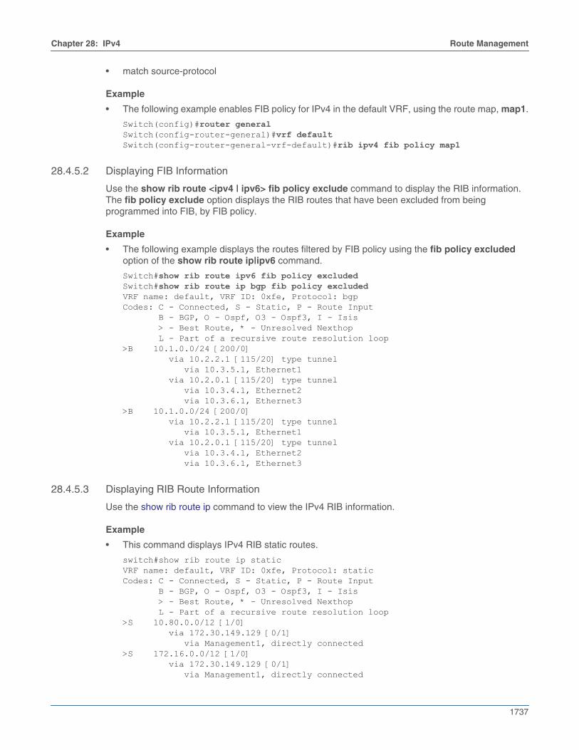
Use the show rib route <ipv4 | ipv6> fib policy exclude command to display the RIB information.The fib policy exclude option displays the RIB routes that have been excluded from beingprogrammed into FIB, by FIB policy.
Example
• The following example displays the routes filtered by FIB policy using the fib policy excludedoption of the show rib route ip|ipv6 command.
Switch#show rib route ipv6 fib policy excludedSwitch#show rib route ip bgp fib policy excludedVRF name: default, VRF ID: 0xfe, Protocol: bgpCodes: C - Connected, S - Static, P - Route Input B - BGP, O - Ospf, O3 - Ospf3, I - Isis > - Best Route, * - Unresolved Nexthop L - Part of a recursive route resolution loop>B 10.1.0.0/24 [200/0] via 10.2.2.1 [115/20] type tunnel via 10.3.5.1, Ethernet1 via 10.2.0.1 [115/20] type tunnel via 10.3.4.1, Ethernet2 via 10.3.6.1, Ethernet3 >B 10.1.0.0/24 [200/0] via 10.2.2.1 [115/20] type tunnel via 10.3.5.1, Ethernet1 via 10.2.0.1 [115/20] type tunnel via 10.3.4.1, Ethernet2 via 10.3.6.1, Ethernet3
28.4.5.3 Displaying RIB Route Information
Use the show rib route ip command to view the IPv4 RIB information.
Example
• This command displays IPv4 RIB static routes.
switch#show rib route ip staticVRF name: default, VRF ID: 0xfe, Protocol: staticCodes: C - Connected, S - Static, P - Route Input B - BGP, O - Ospf, O3 - Ospf3, I - Isis > - Best Route, * - Unresolved Nexthop L - Part of a recursive route resolution loop>S 10.80.0.0/12 [1/0] via 172.30.149.129 [0/1] via Management1, directly connected>S 172.16.0.0/12 [1/0] via 172.30.149.129 [0/1] via Management1, directly connected

1738
Route Management Chapter 28: IPv4
switch#

Chapter 28: IPv4 IPv4 Route Scale
1739
28.5 IPv4 Route ScaleIPv4 routes are optimized to achieve route scale when route distribution has a large number of routesof one or two parameters, with each parameter consisting of prefix lengths 12, 16, 20, 24, 28, and 32.If two separate prefix lengths are configured (in any order), one of them must be the prefix length of 32.
The following sections describes IPv4 route scale configuration, show commands, and system logmessages:
• Section 28.5.1: Configuring IPv4 Route Scale
• Section 28.5.2: Show Commands
• Section 28.5.3: Syslog
28.5.1 Configuring IPv4 Route Scale
IPv4 route scale is enabled by the ip hardware fib optimize command for the configuration modeinterface. The platform layer 3 agent is restarted to ensure IPv4 routes are optimized with the agentSandL3Unicast terminate command for the configuration mode interface.
Example
• This configuration command allows configuring prefix lengths 12 and 32.
switch(config)#ip hardware fib optimize exact-match prefix-length 12 32! Please restart layer 3 forwarding agent to ensure IPv4 routes are optimized
One of the two prefixes in this command is a prefix-length of 32, which is required in the instancewhere there are two prefixes. For this command to take effect, the platform layer 3 agent must berestarted.
This configuration command restarts the platform layer 3 agent to ensure IPv4 routes areoptimized.
switch(config)#agent SandL3Unicast terminateSandL3Unicast was terminated
Restarting the platform layer 3 agent results in deletion of all IPv4 routes, which are re-added tothe hardware.
Example
• This configuration command allows configuring prefix lengths 32 and 16.
switch(config)#ip hardware fib optimize exact-match prefix-length 32 16! Please restart layer 3 forwarding agent to ensure IPv4 routes are optimized
One of the two prefixes in this command is a prefix-length of 32, which is required in the instancewhere there are two prefixes. For this command to take effect, the platform layer 3 agent must berestarted.
This configuration command restarts the platform layer 3 agent to ensure IPv4 routes areoptimized.
switch(config)#agent SandL3Unicast terminateSandL3Unicast was terminated
Restarting the platform layer 3 agent results in deletion of all IPv4 routes, which are re-added tothe hardware.
1740
IPv4 Route Scale Chapter 28: IPv4
Example
• This configuration command allows configuring prefix length 24.
switch(config)#ip hardware fib optimize exact-match prefix-length 24! Please restart layer 3 forwarding agent to ensure IPv4 routes are optimized
In this instance, there is only one prefix-length, so a prefix-length of 32 is not required. For thiscommand to take effect, the platform layer 3 agent must be restarted.
This configuration command restarts the platform layer 3 agent to ensure IPv4 routes areoptimized.
switch(config)#agent SandL3Unicast terminateSandL3Unicast was terminated
Restarting the platform layer 3 agent results in deletion of all IPv4 routes, which are re-added tothe hardware.
Example
• This configuration command allows configuring prefix length 32.
switch(config)#ip hardware fib optimize exact-match prefix-length 32! Please restart layer 3 forwarding agent to ensure IPv4 routes are optimized
For this command to take effect, the platform layer 3 agent must be restarted.
This configuration command restarts the platform layer 3 agent to ensure IPv4 routes areoptimized.
switch(config)#agent SandL3Unicast terminateSandL3Unicast was terminated
Restarting the platform layer 3 agent results in deletion of all IPv4 routes, which are re-added tothe hardware.
Example
• This configuration command disables configuring prefix lengths 12 and 32.
switch(config)#no ip hardware fib optimize exact-match prefix-length 12 32! Please restart layer 3 forwarding agent to ensure IPv4 routes are not optimized
One of the two prefixes in this command is a prefix-length of 32, which is required in the instancewhere there are two prefixes. For this command to take effect, the platform layer 3 agent must berestarted.
This configuration command restarts the platform layer 3 agent to ensure IPv4 routes are notoptimized.
switch(config)#agent SandL3Unicast terminateSandL3Unicast was terminated
Restarting the platform layer 3 agent results in deletion of all IPv4 routes, which are re-added tothe hardware.
Example
• This configuration command attempts to configure prefix length 20 and 28 which triggers an errorexception. One of the two prefixes in this command must be a prefix-length of 32, which is requiredin the instance where there are two prefixes.
switch(config)#ip hardware fib optimize exact-match prefix-length 20 28% One of the prefix lengths must be 32

Chapter 28: IPv4 IPv4 Route Scale
1741
28.5.2 Show Commands
The IPv4 route scale summary is displayed by the show platform arad ip route summary command forthe configuration mode interface. Resources for all IPv4 route scale routes are displayed by the showplatform arad ip route command for the configuration mode interface.
Example
This command shows hardware resource usage of IPv4 routes.
switch(config)#show platform arad ip route summaryTotal number of VRFs: 1Total number of routes: 25Total number of route-paths: 21Total number of lem-routes: 4
Example
This command shows resources for all IPv4 routes in hardware. Routes that use the additionalhardware resources will appear with an asterisk.
switch(config)#show platform arad ip routeTunnel Type: M(mpls), G(gre)* - Routes in LEM ------------------------------------------------------------------------------------------------| Routing Table | ||------------------------------------------------------------------------------------------------|VRF| Destination | | | |Acl | |ECMP | FEC | Tunnel|ID | Subnet | Cmd | Destination |VID |Label| MAC / CPU Code |Index|Index|T Value ------------------------------------------------------------------------------------------------|0 |0.0.0.0/8 |TRAP |CoppSystemL3DstMiss|0 | - |ArpTrap | - |1030 | - |0 |100.1.0.0/32 |TRAP |CoppSystemIpBcast |0 | - |BcastReceive | - |1032 | - |0 |100.1.0.0/32 |TRAP |CoppSystemIpUcast |0 | - |Receive | - |32766| - |0 |100.1.255.255/32|TRAP |CoppSystemIpBcast |0 | - |BcastReceive | - |1032 | - |0 |200.1.255.255/32|TRAP |CoppSystemIpBcast |0 | - |BcastReceive | - |1032 | - |0 |200.1.0.0/16 |TRAP |CoppSystemL3DstMiss|1007| - |ArpTrap | - |1029 | - |0 |0.0.0.0/0 |TRAP |CoppSystemL3LpmOver|0 | - |SlowReceive | - |1024 | - |0 |4.4.4.0/24* |ROUTE|Et10 |1007| - |00:01:00:02:00:03| - |1033 | - |0 |10.20.30.0/24* |ROUTE|Et9 |1006| - |00:01:00:02:00:03| - |1027 | -

1742
IPv4 Route Scale Chapter 28: IPv4
28.5.3 Syslog
When the number of routes exceed additional hardware resources, the ROUTING_LEM_RESOURCE_FULLsyslog message is displayed.

Chapter 28: IPv4 IP Source Guard
1743
28.6 IP Source GuardIP Source Guard (IPSG) prevents IP spoofing attacks. It filters inbound IP packets based on theirsource MAC and IP addresses. IPSG is supported in hardware. IPSG enabled on a Layer 2 port verifiesIP packets received on this port. Packets are permitted if each packet source MAC and IP addressesmatch any of the user-configured IP-MAC binding entries on the receiving VLAN and port. Packets withno match are dropped immediately.
28.6.1 Configuring IPSG
IPSG is applicable only to Layer 2 ports, and is enabled by the ip verify source command for theconfiguration mode interface. When configured on Layer 3 ports, IPSG does not take effect until thisinterface is converted to Layer 2.
IPSG is supported on Layer 2 Port-Channels, not member ports. The IPSG configuration on portchannels supersedes the configuration on the physical member ports. Hence, source IP MAC bindingentries should be configured on port channels using the ip source binding command. When configuredon a port channel member port, IPSG does not take effect until this port is deleted from the port channelconfiguration.
Example
• These configuration commands exclude VLAN IDs 1 through 3 from IPSG filtering. When enabledon a trunk port, IPSG filters the inbound IP packets on all allowed VLANs. IP packets received onVLANs 4 through 10 on Ethernet 36 will be filtered by IPSG, while those received on VLANs 1through 3 are permitted.
switch(config)#no ip verify source vlan 1-3switch(config)#interface ethernet 36switch(config-if-Et36)#switchport mode trunkswitch(config-if-Et36)#switchport trunk allowed vlan 1-10switch(config-if-Et36)#ip verify sourceswitch(config-if-Et36)#
This configuration command configures source IP-MAC binding entries to IP address 10.1.1.1,MAC address 0000.aaaa.1111, VLAN ID 4094, and Ethernet interface 36.
switch(config)#ip source binding 10.1.1.1 0000.aaaa.1111 vlan 4094 interface ethernet 36switch(config)#
28.6.2 Show Commands
The IPSG configuration and operational states and IP-MAC binding entries are displayed by the showip verify source command for the configuration mode interface.
Example
This command verifies the IPSG configuration and operational states.
switch(config)#show ip verify sourceInterface Operational State--------------- ------------------------Ethernet1 IP source guard enabledEthernet2 IP source guard disabled

1744
IP Source Guard Chapter 28: IPv4
Example
This command displays all VLANs configured in no ip verify source vlan. Hardware programmingerrors, e.g.,VLAN classification failed, are indicated in the operational state. If an error occurs, thisVLAN will be considered as enabled for IPSG. Traffic on this VLAN will still be filtered by IPSG.
switch(config)#show ip verify source vlanIPSG disabled on VLANS: 1-2VLAN Operational State--------------- ------------------------1 IP source guard disabled2 Error: vlan classification failed
Example
This command displays all source IP-MAC binding entries configured for IPSG. A source binding entryis considered active if it is programmed in hardware. IP traffic matching any active binding entry will bepermitted. If a source binding entry is configured on an interface or a VLAN whose operational state isIPSG disabled, this entry will not be installed in the hardware, in which case an “IP source guarddisabled” state will be shown. If a port channel has no member port configured, binding entriesconfigured for this port channel will not be installed in hardware, and a “Port-Channel down” state willbe shown.
switch(config)#show ip verify source detailInterface IP Address MAC Address VLAN State--------------- ------------- ---------------- ------ ------------------------Ethernet1 10.1.1.1 0000.aaaa.1111 5 activeEthernet1 10.1.1.5 0000.aaaa.5555 1 IP source guard disabledPort-Channel1 20.1.1.1 0000.bbbb.1111 4 Port-Channel down
Chapter 28: IPv4 DHCP Relay Across VRF
1745
28.7 DHCP Relay Across VRFThe EOS DHCP relay agent supports forwarding of DHCP requests to DHCP servers located in adifferent VRF to the DHCP client interface VRF. In order to enable VRF support for the DHCP relayagent, Option 82 (DHCP Relay Agent Information Option) must first be enabled. The DHCP relay agentuses Option 82 to pass client specific information to the DHCP server.
These sections describe DHCP Relay across VRF features:
• Section 28.7.1: Global Configuration
• Section 28.7.2: Show Command
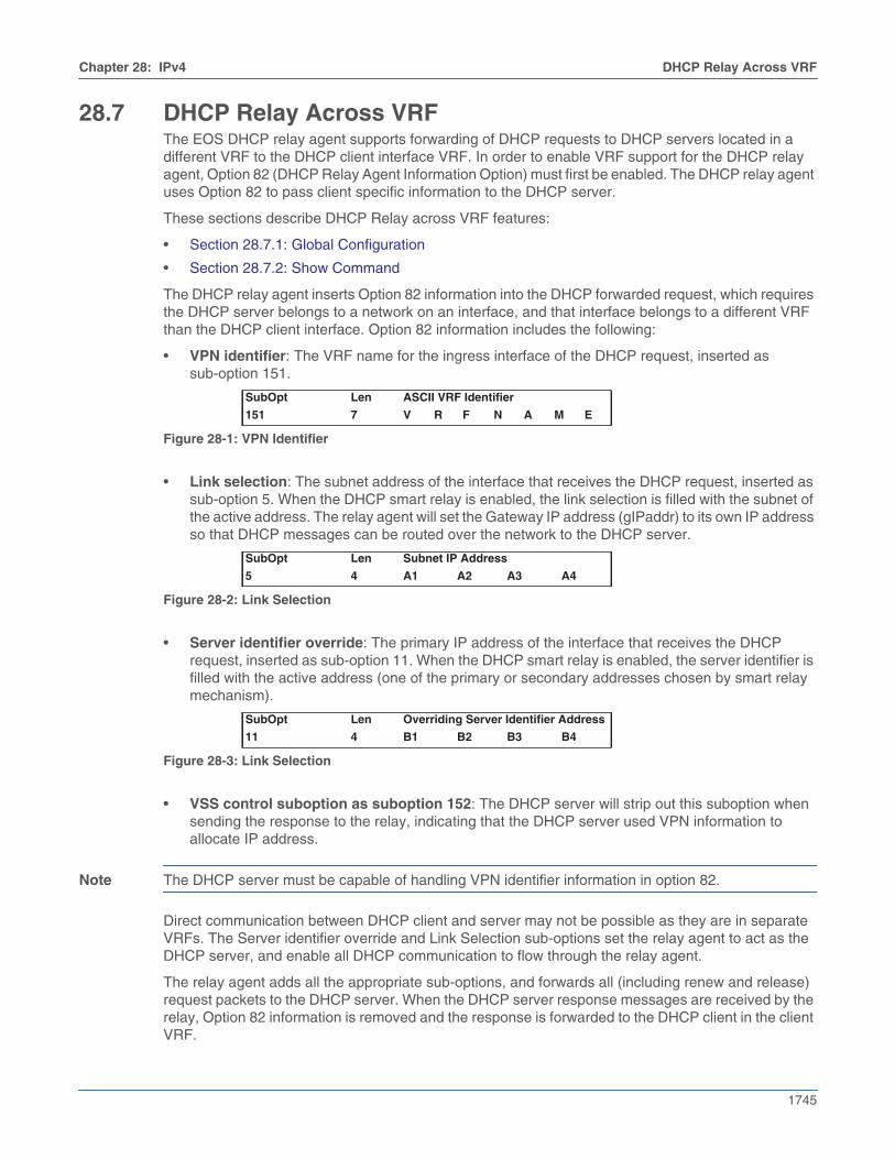
The DHCP relay agent inserts Option 82 information into the DHCP forwarded request, which requiresthe DHCP server belongs to a network on an interface, and that interface belongs to a different VRFthan the DHCP client interface. Option 82 information includes the following:
• VPN identifier: The VRF name for the ingress interface of the DHCP request, inserted assub-option 151.
• Link selection: The subnet address of the interface that receives the DHCP request, inserted assub-option 5. When the DHCP smart relay is enabled, the link selection is filled with the subnet ofthe active address. The relay agent will set the Gateway IP address (gIPaddr) to its own IP addressso that DHCP messages can be routed over the network to the DHCP server.
• Server identifier override: The primary IP address of the interface that receives the DHCPrequest, inserted as sub-option 11. When the DHCP smart relay is enabled, the server identifier isfilled with the active address (one of the primary or secondary addresses chosen by smart relaymechanism).
• VSS control suboption as suboption 152: The DHCP server will strip out this suboption whensending the response to the relay, indicating that the DHCP server used VPN information toallocate IP address.
Note The DHCP server must be capable of handling VPN identifier information in option 82.
Direct communication between DHCP client and server may not be possible as they are in separateVRFs. The Server identifier override and Link Selection sub-options set the relay agent to act as theDHCP server, and enable all DHCP communication to flow through the relay agent.
The relay agent adds all the appropriate sub-options, and forwards all (including renew and release)request packets to the DHCP server. When the DHCP server response messages are received by therelay, Option 82 information is removed and the response is forwarded to the DHCP client in the clientVRF.
SubOpt Len ASCII VRF Identifier
151 7 V R F N A M E
Figure 28-1: VPN Identifier
SubOpt Len Subnet IP Address
5 4 A1 A2 A3 A4
Figure 28-2: Link Selection
SubOpt Len Overriding Server Identifier Address
11 4 B1 B2 B3 B4
Figure 28-3: Link Selection
1746
DHCP Relay Across VRF Chapter 28: IPv4
28.7.1 Global Configuration
The DHCP relay agent information option is inserted in DHCP messages relayed to the DHCP server.The ip helper-address command enables DHCP relay on an interface; and relays DHCP messages tothe specified IPv4 address.
Example
This command enables DHCP relay on the interface Ethernet 1/2; and relays DHCP messages to theserver at 1.1.1.1.
switch(config)#interface ethernet 1/2switch(config-if-Et1/2)#ip helper-address 1.1.1.1switch(config-if-Et1/2)#
The commands provided in examples below will turn on the attachment of VRF-related tags in the relayagent information option. If both the DHCP client interface and server interface are on the same VRF(default or non-default), then no VRF-related DHCP relay agent information option is inserted.
Examples
• This command configures the DHCP relay to add option 82 information.
switch(config)#ip dhcp relay information option
• These commands configures two new VRF instances and assign them Route Distinguishers(RDs).
switch(config)#vrf instance mtxxg-vrfswitch(config-vrf-mtxxg-vrf)#router bgp 50switch(config-router-bgp)#vrf mtxxg-vrfswitch(config-router-bgp-vrf-mtxxg-vrf)#rd 5546:5546
switch(config)#vrf instance qchyh-vrfswitch(config-vrf-qchyh-vrf)#router bgp 50switch(config-router-bgp)#vrf qchyh-vrfswitch(config-router-bgp-vrf-qchyh-vrf)#rd 218:218
• This command configures an interface connected to DHCP client in vrf mtxxg-vrf and assigns anIP address.
switch(config)#interface Ethernet 9switch(config-if-Et9)#no switchport
• This command configures the DHCP client interface in VRF mtxxg-vrf.
switch(config-if-Et9)#vrf mtxxg-vrfswitch(config-if-Et9)#ip address 10.10.0.1/16
• This command configures the server interface in VRF qchyh-vrf.
switch(config-if-Et11)#vrf qchyh-vrfswitch(config-if-Et11)#ip address 10.40.0.1/16
• This command configures a helper address for a DHCP server in VRF qchyh-vrf.
switch(config-if-Et11)#ip helper-address 10.40.2.3 vrf qchyh-vrf
Chapter 28: IPv4 DHCP Relay Across VRF
1747
28.7.2 Show Command
Example
This command displays the VRF specifier for the server:
rtr1#show ip dhcp relayDHCP Relay is activeDHCP Relay Option 82 is enabledDHCP Smart Relay is disabledInterface: Ethernet9Option 82 Circuit ID: Ethernet9DHCP Smart Relay is disabledDHCP servers: 10.40.2.310.40.2.3:vrf=qchyh-vrf
1748
IP NAT Chapter 28: IPv4
28.8 IP NATNetwork address translation (NAT) is a router process that modifies address information of IP packetsin transit. NAT is typically used to correlate address spaces between a local network and a remote,often public, network. Static NAT defines a one-to-one map between local and remote IP addresses.Static maps are configured manually through CLI commands. An interface can support multiple NATcommands, but each command must specify a unique local IP address-port location.
NAT is configured on routers that have interfaces connecting to the local networks and interfacesconnecting to a remote network.
NAT is available only on FM6000 platform switches (the 7150 series).
Inside and Outside Addresses
In NAT configurations, IP addresses are placed into one of two categories: inside or outside. Insiderefers to IP addresses used within the organizational network. Outside refers to addresses on anexternal network outside the organizational network.
28.8.1 Static IP NAT
Static NAT configurations create a one-to-one mapping and translate a particular address to anotheraddress. This type of configuration creates a permanent entry in the NAT table as long as theconfiguration is present, and it enables both inside and outside hosts to initiate a connection.
Static NAT options include source NAT, destination NAT, and twice NAT.
• Source NAT modifies the source address in the IP header of a packet exiting the interface, and canoptionally change the source port referenced in the TCP/UDP headers.
• Destination NAT modifies the destination address in the IP header of a packet entering theinterface, and can optionally change the destination port referenced in the TCP/UDP headers.
• Twice NAT modifies both the source and destination address of packets entering and exiting theinterface, and can optionally change the L4 port information in the TCP/UDP headers. Twice NATis generally used when inside network addresses overlap or otherwise conflict with outside networkaddresses. When a packet exits the interface, local source and destination addresses aretranslated to global source and destination addresses. When a packet enters the interface, globalsource and destination addresses are translated to local source and destination addresses.
28.8.1.1 Configuring Static NAT
Configuring Source NAT
Network address translation of a source address (source NAT) is enabled by the ip nat source staticcommand for the configuration mode interface. Applying source NAT to interfaces that connect to localhosts shields the IP address of the host when sending IP packets to remote destinations.
This command installs hardware translation entries for forward and reverse unicast traffic. When therule specifies a multicast group, the command does not install the reverse path in hardware. Thecommand may include an access control list to filter packets for translation.
Note The switch uses a common NAT table for the entire switch, not a per interface one. For example, if acustomer has the same inside local address translated to different inside global addresses dependingon which interface it exits. It might be translated to exit interface B’s inside global address even thoughit exits through interface A. A way to avoid this is to use an access list that differentiates based on thedestination IP address.
Chapter 28: IPv4 IP NAT
1749
Example
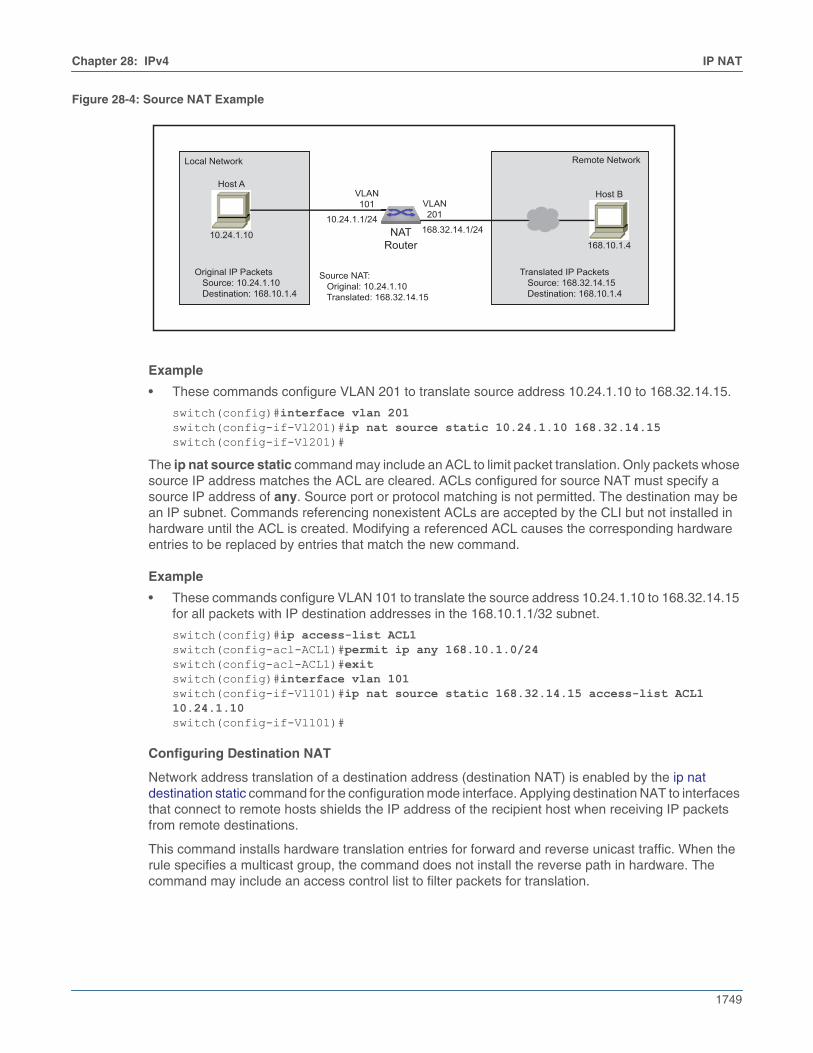
• These commands configure VLAN 201 to translate source address 10.24.1.10 to 168.32.14.15.
switch(config)#interface vlan 201switch(config-if-Vl201)#ip nat source static 10.24.1.10 168.32.14.15 switch(config-if-Vl201)#
The ip nat source static command may include an ACL to limit packet translation. Only packets whosesource IP address matches the ACL are cleared. ACLs configured for source NAT must specify asource IP address of any. Source port or protocol matching is not permitted. The destination may bean IP subnet. Commands referencing nonexistent ACLs are accepted by the CLI but not installed inhardware until the ACL is created. Modifying a referenced ACL causes the corresponding hardwareentries to be replaced by entries that match the new command.
Example
• These commands configure VLAN 101 to translate the source address 10.24.1.10 to 168.32.14.15for all packets with IP destination addresses in the 168.10.1.1/32 subnet.
switch(config)#ip access-list ACL1switch(config-acl-ACL1)#permit ip any 168.10.1.0/24switch(config-acl-ACL1)#exitswitch(config)#interface vlan 101switch(config-if-Vl101)#ip nat source static 168.32.14.15 access-list ACL1 10.24.1.10switch(config-if-Vl101)#
Configuring Destination NAT
Network address translation of a destination address (destination NAT) is enabled by the ip natdestination static command for the configuration mode interface. Applying destination NAT to interfacesthat connect to remote hosts shields the IP address of the recipient host when receiving IP packetsfrom remote destinations.
This command installs hardware translation entries for forward and reverse unicast traffic. When therule specifies a multicast group, the command does not install the reverse path in hardware. Thecommand may include an access control list to filter packets for translation.
Figure 28-4: Source NAT Example
Local Network
Original IP Packets Source: 10.24.1.10 Destination: 168.10.1.4
Remote Network
NAT Router
10.24.1.10
Host AHost B
168.10.1.4
VLAN101 VLAN
201
Translated IP Packets Source: 168.32.14.15 Destination: 168.10.1.4
10.24.1.1/24168.32.14.1/24
Source NAT: Original: 10.24.1.10 Translated: 168.32.14.15
1750
IP NAT Chapter 28: IPv4
Example
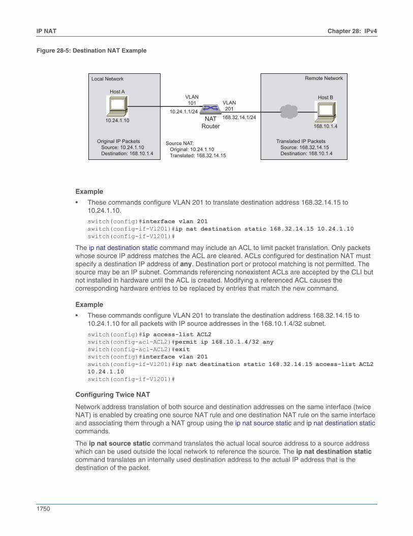
• These commands configure VLAN 201 to translate destination address 168.32.14.15 to10.24.1.10.
switch(config)#interface vlan 201switch(config-if-Vl201)#ip nat destination static 168.32.14.15 10.24.1.10 switch(config-if-Vl201)#
The ip nat destination static command may include an ACL to limit packet translation. Only packetswhose source IP address matches the ACL are cleared. ACLs configured for destination NAT mustspecify a destination IP address of any. Destination port or protocol matching is not permitted. Thesource may be an IP subnet. Commands referencing nonexistent ACLs are accepted by the CLI butnot installed in hardware until the ACL is created. Modifying a referenced ACL causes thecorresponding hardware entries to be replaced by entries that match the new command.
Example
• These commands configure VLAN 201 to translate the destination address 168.32.14.15 to10.24.1.10 for all packets with IP source addresses in the 168.10.1.4/32 subnet.
switch(config)#ip access-list ACL2switch(config-acl-ACL2)#permit ip 168.10.1.4/32 anyswitch(config-acl-ACL2)#exitswitch(config)#interface vlan 201switch(config-if-Vl201)#ip nat destination static 168.32.14.15 access-list ACL2 10.24.1.10switch(config-if-Vl201)#
Configuring Twice NAT
Network address translation of both source and destination addresses on the same interface (twiceNAT) is enabled by creating one source NAT rule and one destination NAT rule on the same interfaceand associating them through a NAT group using the ip nat source static and ip nat destination staticcommands.
The ip nat source static command translates the actual local source address to a source addresswhich can be used outside the local network to reference the source. The ip nat destination staticcommand translates an internally used destination address to the actual IP address that is thedestination of the packet.
Figure 28-5: Destination NAT Example
Local Network
Original IP Packets Source: 10.24.1.10 Destination: 168.10.1.4
Remote Network
NAT Router
10.24.1.10
Host AHost B
168.10.1.4
VLAN101 VLAN
201
Translated IP Packets Source: 168.32.14.15 Destination: 168.10.1.4
10.24.1.1/24168.32.14.1/24
Source NAT: Original: 10.24.1.10 Translated: 168.32.14.15
Chapter 28: IPv4 IP NAT
1751
The source and destination NAT rules must reference the same NAT group, and both should eitherspecify only IP addresses or specify both IP addresses and L4 port information. If L4 port informationis configured in one rule but not in the other, an error message will be displayed.
Each NAT rule installs hardware translation entries for forward and reverse unicast traffic. When therule specifies a multicast group, the command does not install the reverse path in hardware. Twice NATdoes not support the use of access control lists to filter packets for translation.
Example
• These commands configure Ethernet interface 2 to translate the local source address 10.24.1.10to the global source address 168.32.14.15, and to translate the local destination address10.68.104.3 to the global destination address 168.25.10.7 for all packets moving through theinterface. The use of NAT group 3 is arbitrary, but must be the same in both rules.
switch(config)#interface ethernet 2switch(config-if-Et2)#ip nat source static 10.24.1.10 168.32.14.15 group 3switch(config-if-Et2)#ip nat destination static 10.68.104.3 168.25.10.7 group 3
28.8.1.2 Static NAT Configuration Considerations
Egress VLAN filter for static NAT
When a static source NAT is configured on an interface, the source IP translation happens only forthose packets that is going 'out' of this interface. If a packet is egressing on an interface which does nothave NAT configured, then the source IP is not translated.
When there are two interfaces on which static SNAT is configured then the translation specified for oneinterface can be applied to a packet going out on the other interface.
Example
• In this example, the packets with source IP 20.1.1.1 going out of E1 will still have the source IPtranslated to 172.1.1.1 even though the rule is configured in E2 and not on E1.
switch(config)#interface ethernet 1switch(config-if-Et1)# ip nat source static 10.1.1.1 171.1.1.1switch(config)#interface ethernet 2switch(config-if-Et2)#ip nat source static 20.1.1.1 172.1.1.1
To prevent this, use an ACL to filter the traffic that needs NAT on the interfaces.
switch(config)#ip access-list acl1switch(config-acl-acl1)#permit ip any 171.1.1.0/24switch(config)#ip access-list acl2switch(config-acl-acl2)#permit ip any 172.1.1.0/24switch(config)#interface ethernet 1switch(config-if-Et1)# ip nat source static 10.1.1.1 access-list acl1 171.1.1.1switch(config)#interface ethernet 2switch(config-if-Et2)#ip nat source static 20.1.1.1 access-list acl2 172.1.1.1
ACL filtering is not supported when using twice NAT.
28.8.2 Dynamic NAT
Dynamic NAT can be used when fewer addresses are accessible than the number of hosts to betranslated. A NAT table entry is created when the host starts a connection and establishes a one-to-onemapping between addresses. The mapping can vary and is dependent upon the registered addressesin the pool at the time of the communication. Dynamic NAT sessions are only allowed to be initiatedonly from inside networks. NAT should be configured on a Layer 3 interface, either a routed port or

1752
IP NAT Chapter 28: IPv4
Switch Virtual Interface (SVI). If the host doesn't communicate for a specific period, dynamic NATentries are removed from the translation table. The address will then returned to the pool for use byanother host
Dynamic NAT options:
• Many-to-Many NAT
Maps local addresses to a global address that is selected from a pool of global addresses. Afterpool is configured, the first available address from the pool is picked dynamically on receiving thefirst packet.
• Many-to-One NAT (PAT)
PAT is a form of dynamic NAT where multiple local addresses are mapped to a single globaladdress (many-to-one) using different source ports. This method is also called NAT Overloading,NAPT (Network and Port address translation), and Masquerade. The global address can be the IPaddress configured on the outside interface.
Hardware entries that translate packets are created when the CLI command is processed. Entriesfor forward and reverse traffic are created for unicast traffic. The hardware entry for reverse trafficis not created for multicast traffic.
Commands may include ACLs to filter packets that are cleared. Source NAT use ACLs to filterpackets based on destination IP address. Destination NAT use ACLs to filter packets based onsource IP address. Upon using NAT, inside usually refers to a private network while outside usuallyrefers to a public network.
A switch with NAT configured translates forwarded traffic between inside and outside interfaces,and the flow that matches the criteria specified for translation.
The same IP address can't be used for the NAT static configuration and in the pool for dynamicNAT configurations. Public IP addresses must be unique. The global addresses used in statictranslations aren't excluded with dynamic pools containing the same global addresses.
Hardware entries that translate packets are created when the CLI command is processed. Entries forforward and reverse traffic are created for unicast traffic. The hardware entry for reverse traffic is notcreated for multicast traffic.
Figure 28-6: Dynamic NAT Scenario
10.1.1.1
H1
H3
171.16.1.2
Internet
NAT Device
Outside NetworkInside Network
10.1.1.2
H2
Et2Et1
H1 H3 H1 H3
H2 H3 H2 H3
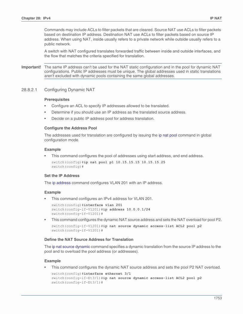
Chapter 28: IPv4 IP NAT
1753
Commands may include ACLs to filter packets that are cleared. Source NAT use ACLs to filter packetsbased on destination IP address. Destination NAT use ACLs to filter packets based on source IPaddress. When using NAT, inside usually refers to a private network while outside usually refers to apublic network.
A switch with NAT configured translates forwarded traffic between inside and outside interfaces, andthe flow that matches the criteria specified for translation.
Important! The same IP address can't be used for the NAT static configuration and in the pool for dynamic NATconfigurations. Public IP addresses must be unique. The global addresses used in static translationsaren't excluded with dynamic pools containing the same global addresses.
28.8.2.1 Configuring Dynamic NAT
Prerequisites
• Configure an ACL to specify IP addresses allowed to be translated.
• Determine if you should use an IP address as the translated source address.
• Decide on a public IP address pool for address translation.
Configure the Address Pool
The addresses used for translation are configured by issuing the ip nat pool command in globalconfiguration mode.
Example
• This command configures the pool of addresses using start address, and end address.
switch(config)#ip nat pool p1 10.15.15.15 10.15.15.25 switch(config)#
Set the IP Address
The ip address command configures VLAN 201 with an IP address.
Example
• This command configures an IPv4 address for VLAN 201.
switch(config)#interface vlan 201switch(config-if-Vl201)#ip address 10.0.0.1/24switch(config-if-Vl201)#
• This command configures the dynamic NAT source address and sets the NAT overload for pool P2.
switch(config-if-Vl201)#ip nat source dynamic access-list ACL2 pool p2switch(config-if-Vl201)#
Define the NAT Source Address for Translation
The ip nat source dynamic command specifies a dynamic translation from the source IP address to thepool and to overload the pool address (or addresses).
Example
• This command configures the dynamic NAT source address and sets the pool P2 NAT overload.
switch(config)#interface ethernet 3/1switch(config-if-Et3/1)#ip nat source dynamic access-list ACL2 pool p2switch(config-if-Et3/1)#

1754
IP NAT Chapter 28: IPv4
Specify the Timeout Values
The ip nat translation tcp-timeout or ip nat translation udp-timeout commands alter the translationtimeout period for NAT translation table entries.
Example
• This command globally sets the timeout for TCP to 600 seconds.
switch(config)# ip nat translation tcp-timeout 600switch(config)#
• This command globally sets the timeout for UDP to 800 seconds.
switch(config)# ip nat translation udp-timeout 800switch(config)#
28.8.2.2 Verify the NAT Configuration
Display the Address Pools
The show ip nat pool command displays the configuration of the address pool.
Example
• This command displays all the address pools configured on the switch.
switch#show ip nat poolPool StartIp EndIp Prefixp1 10.15.15.15 10.15.15.25 24p2 10.10.15.15 10.10.15.25 22p3 10.12.15.15 10.12.15.25 12switch#
28.8.2.3 Clearing IP NAT Table Entries
Use the clear ip nat flow translation command to remove all or the specified NAT table entries.
Example
• This command clears all dynamic entries from the NAT table.
switch#clear ip nat flow translationswitch#
28.8.2.4 Dynamic NAT Configuration Considerations
Configuring Dynamic NAT Using Pools in a L2 Adjacent Network
When many-to-one dynamic NAT is configured using a NAT pool, and the next hop router for the NATdevice is on the same network (L2 adjacent), then you must configure the IP addresses in the NAT poolas a secondary address on the interface.
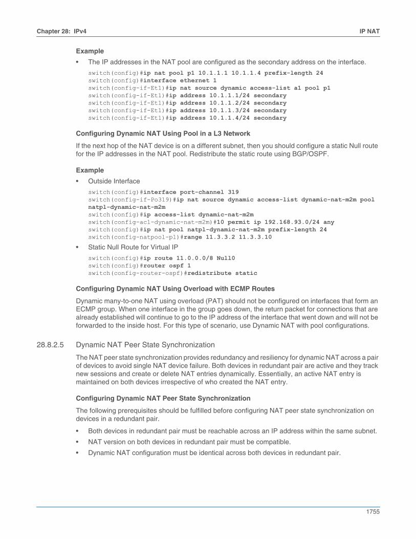
Chapter 28: IPv4 IP NAT
1755
Example
• The IP addresses in the NAT pool are configured as the secondary address on the interface.
switch(config)#ip nat pool p1 10.1.1.1 10.1.1.4 prefix-length 24switch(config)#interface ethernet 1switch(config-if-Et1)#ip nat source dynamic access-list a1 pool p1switch(config-if-Et1)#ip address 10.1.1.1/24 secondaryswitch(config-if-Et1)#ip address 10.1.1.2/24 secondaryswitch(config-if-Et1)#ip address 10.1.1.3/24 secondaryswitch(config-if-Et1)#ip address 10.1.1.4/24 secondary
Configuring Dynamic NAT Using Pool in a L3 Network
If the next hop of the NAT device is on a different subnet, then you should configure a static Null routefor the IP addresses in the NAT pool. Redistribute the static route using BGP/OSPF.
Example
• Outside Interface
switch(config)#interface port-channel 319switch(config-if-Po319)#ip nat source dynamic access-list dynamic-nat-m2m pool natpl-dynamic-nat-m2mswitch(config)#ip access-list dynamic-nat-m2mswitch(config-acl-dynamic-nat-m2m)#10 permit ip 192.168.93.0/24 anyswitch(config)#ip nat pool natpl-dynamic-nat-m2m prefix-length 24switch(config-natpool-p1)#range 11.3.3.2 11.3.3.10
• Static Null Route for Virtual IP
switch(config)#ip route 11.0.0.0/8 Null0switch(config)#router ospf 1switch(config-router-ospf)#redistribute static
Configuring Dynamic NAT Using Overload with ECMP Routes
Dynamic many-to-one NAT using overload (PAT) should not be configured on interfaces that form anECMP group. When one interface in the group goes down, the return packet for connections that arealready established will continue to go to the IP address of the interface that went down and will not beforwarded to the inside host. For this type of scenario, use Dynamic NAT with pool configurations.
28.8.2.5 Dynamic NAT Peer State Synchronization
The NAT peer state synchronization provides redundancy and resiliency for dynamic NAT across a pairof devices to avoid single NAT device failure. Both devices in redundant pair are active and they tracknew sessions and create or delete NAT entries dynamically. Essentially, an active NAT entry ismaintained on both devices irrespective of who created the NAT entry.
Configuring Dynamic NAT Peer State Synchronization
The following prerequisites should be fulfilled before configuring NAT peer state synchronization ondevices in a redundant pair.
• Both devices in redundant pair must be reachable across an IP address within the same subnet.
• NAT version on both devices in redundant pair must be compatible.
• Dynamic NAT configuration must be identical across both devices in redundant pair.
1756
IP NAT Chapter 28: IPv4
The following configuration output indicates a valid running configuration of the NAT peer statesynchronization on one device.
ip nat pool POOL61 prefix-length 24 range 170.24.0.2 170.24.0.200
ip access-list NatACL61 10 permit ip 61.0.0.0/16 any
interface Port-Channel5 mtu 9214 no switchport ip address 10.0.0.1/31 ip nat source dynamic access-list NatACL61 pool POOL61
ip nat synchronization peer-address 11.11.11.1 local-interface Vlan1111 port-range 1024 2048
The following limitations are applicable during NAT peer state synchronization.
• While configuring dynamic NAT peer state synchronization across peer switches, the port rangevalues of the switches should always be disjoint to avoid virtual IP conflict.
• NAT peer state synchronization does not support asymmetrical TCP setup (SYN - SYNACK - ACKshould always be hashed to the same peer.)
• The connection is only synchronized with a peer if the TCP state is established.
Chapter 28: IPv4 TCP MSS Clamping
1757
28.9 TCP MSS ClampingTCP MSS clamping limits the value of the maximum segment size (MSS) in the TCP header of TCPSYN packets transiting a specified Ethernet or tunnel interface. Setting the MSS ceiling can avoid IPfragmentation in tunnel scenarios by ensuring that the MSS is low enough to account for the extraoverhead of GRE and tunnel outer IP headers. TCP MSS clamping can be used when connecting viaGRE to cloud providers that require asymmetric routing.
When MSS clamping is configured on an interface, if the TCP MSS value in a SYN packet transitingthat interface exceeds the configured ceiling limit it will be overwritten with the configured limit and theTCP checksum will be recomputed and updated.
TCP MSS clamping is handled by default in the software data path, but the process can be supportedthrough hardware configuration to minimize possible packet loss and a reduction in the number of TCPsessions which the switch can establish per second.
28.9.1 Cautions
This feature should be used with caution. When the TCP MSS clamping feature is enabled by issuingthe tcp mss ceiling command on any routed interface, all routed IPv4 TCP SYN packets (TCP packetswith the “SYN” flag set) are sent by default to the CPU and switched through software, even oninterfaces where no TCP MSS ceiling has been configured, as long as TCP MSS clamping is enabled.This limits the number of TCP sessions that can be established through the switch per second, and,because throughput for software forwarding is limited, this feature can also cause packet loss if the rateat which TCP SYN packets are sent to the CPU exceeds the limits configured in the control-plane policymap.
Packet loss and TCP session reductions can be minimized by enabling TCP MSS clamping inhardware, but only SYN packets in which MSS is the first TCP option are clamped in the hardware datapath; other TCP SYN packets are still switched through software.
To disable MSS clamping, the MSS ceiling must be removed from every interface on which it has beenconfigured by issuing the no tcp mss ceiling command on each configured interface.
28.9.2 Enabling TCP MSS Clamping
There is no global configuration to enable TCP MSS clamping. It is enabled as soon as an MSS ceilingis configured on at least one interface.
28.9.3 Disabling TCP MSS Clamping
To disable TCP MSS clamping, the MSS ceiling configuration must be removed from every interface byusing the no or default form of the tcp mss ceiling command on every interface where a ceiling hasbeen configured.
28.9.4 Configuring the TCP MSS Ceiling on an Interface
The TCP MSS ceiling limit is set on an interface using the tcp mss ceiling command. This also enablesTCP MSS clamping on the switch as a whole.
Caution Configuring a TCP MSS ceiling on any interface enables TCP MSS clamping on the switch as a whole.Without hardware support, clamping routes all TCP SYN packets through software, even on interfaceswhere no TCP MSS ceiling has been configured. This significantly limits the number of TCP sessionsthe switch can establish per second, and can potentially cause packet loss if the CPU traffic exceedscontrol plane policy limits.
1758
TCP MSS Clamping Chapter 28: IPv4
On Sand platform switches (Qumran-MX, Qumran-AX, Jericho, Jericho+), the following limitationsapply:
• This command works only on egress.
• TCP MSS ceiling is supported on IPv4 unicast packets entering the switch; the configuration hasno effect on GRE transit packets.
• The feature is supported only on IPv4 routed interfaces. It is not supported on L2 (switchport)interfaces or IPv6 routed interfaces.
• The feature is not supported for IPv6 packets even if they are going to be tunneled over an IPv4GRE tunnel.
• The feature is not supported on VXLAN, loopback or management interfaces.
• The feature is only supported on IPv4 unicast packets entering the switch. The configuration hasno effect on GRE transit packets or GRE decap, even if the egress interface has a TCP MSS ceilingconfigured.
• The feature cannot co-exist with Policy Based Routing (PBR) on switches running releases 4.21.5For older.
Example
These commands configure Ethernet interface 5 as a routed port, then specify a maximum MSS ceilingvalue of 1458 bytes for TCP SYN packets exiting that port.
switch(config)#interface ethernet 5switch(config-if-Et5)#no switchportswitch(config-if-Et5)#tcp mss ceiling ipv4 1458 egressswitch(config-if-Et5)#
28.9.5 Configuring Hardware Support for TCP MSS Clamping
TCP MSS clamping can be supported in hardware, but some packets are still routed through thesoftware data path, and an MSS ceiling value must be configured on each interface where clamping isto be applied.
Hardware support for clamping is accomplished through the use of a user-defined TCAM profile. TheTCAM profile can be created from scratch or copied from an existing profile, but in either case it mustinclude the tcp-mss-ceiling ip feature.
Guidelines
• When the system TCAM profile is changed, some agents will restart.
• To ensure that the TCP MSS feature is allocated a TCAM DB, it may be necessary to remove someunused features from the TCAM profile.
• Hardware TCP MSS clamping only works for TCP packets with MSS as the first TCP option. OtherTCP SYN packets are still trapped to the CPU for clamping in software.
• Hardware TCP MSS clamping is not supported with host routes when the clamping is applied ona non-tunnel interface. This limitation does not apply to GRE tunnel interfaces.
• The maximum MSS ceiling limit with hardware MSS clamping is 32727 even though the CLI allowsconfiguration of much larger values.
• For more information on the creation of user-defined TCAM profiles, seehttps://eos.arista.com/eos-4-20-5f/user-defined-pmf-profile/.
To configure hardware support for TCP MSS clamping, create a TCAM profile that includes thetcp-mss-ceiling ip feature, then apply it to the system.
Chapter 28: IPv4 TCP MSS Clamping
1759
28.9.5.1 Creating the TCAM Profile
A TCAM profile that supports TCP MSS clamping can be created from scratch, or the feature can beadded to a copy of the default TCAM profile. When creating a profile from scratch, care must be takento ensure that all needed TCAM features are included in the profile.
Modifying a Copy of the Default TCAM Profile
The following commands create a copy of the default TCAM profile, name it “tcp-mss-clamping,” andconfigure it to enable MSS clamping in hardware, then remove some unused features included in thedefault profile to ensure that there are sufficient TCAM resources for the clamping feature.
switch(config)#hardware tcamswitch(config-hw-tcam)#profile tcp-mss-clamping copy defaultswitch(config-hw-tcam-profile-tcp-mss-clampingl)#feature tcp-mss-ceiling ip copy system-feature-source-profileswitch(config-hw-tcam-profile-tcp-mss-clamping-feature-tcp-mss-ceiling)#key size limit 160switch(config-hw-tcam-profile-tcp-mss-clamping-feature-tcp-mss-ceiling)#packet ipv4 forwarding routedswitch(config-hw-tcam-profile-tcp-mss-clamping-feature-tcp-mss-ceiling)#exitswitch(config-hw-tcam-profile-tcp-mss-clamping)#no feature mirror ipswitch(config-hw-tcam-profile-tcp-mss-clamping)#no feature acl port macswitch(config-hw-tcam-profile-tcp-mss-clampingl)#exitswitch(config-hw-tcam)#exitswitch(config)#
28.9.5.2 Applying the TCAM Profile to the System
The following commands enter Hardware TCAM Configuration Mode and set the “tcp-mss-clamping”profile as the system profile.
switch(config)#hardware tcamswitch(config-hw-tcam)#system profile tcp-mss-clampingswitch(config-hw-tcam)#
28.9.5.3 Verifying the TCAM Profile Configuration
The following command displays hardware TCAM profile information to verify that the user-definedTCAM profile has been applied correctly.
switch(config)#show hardware tcam profile
Configuration Status FixedSystem tcp-mss-clamping tcp-mss-clamping switch(config)#
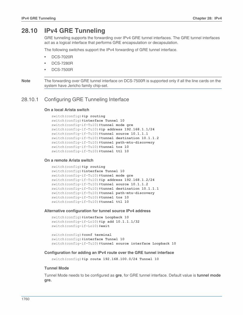
1760
IPv4 GRE Tunneling Chapter 28: IPv4
28.10 IPv4 GRE TunnelingGRE tunneling supports the forwarding over IPv4 GRE tunnel interfaces. The GRE tunnel interfacesact as a logical interface that performs GRE encapsulation or decapsulation.
The following switches support the IPv4 forwarding of GRE tunnel interface.
• DCS-7020R
• DCS-7280R
• DCS-7500R
Note The forwarding over GRE tunnel interface on DCS-7500R is supported only if all the line cards on thesystem have Jericho family chip-set.
28.10.1 Configuring GRE Tunneling Interface
On a local Arista switch
switch(config)#ip routingswitch(config)#interface Tunnel 10switch(config-if-Tu10)#tunnel mode greswitch(config-if-Tu10)#ip address 192.168.1.1/24switch(config-if-Tu10)#tunnel source 10.1.1.1switch(config-if-Tu10)#tunnel destination 10.1.1.2switch(config-if-Tu10)#tunnel path-mtu-discoveryswitch(config-if-Tu10)#tunnel tos 10switch(config-if-Tu10)#tunnel ttl 10
On a remote Arista switch
switch(config)#ip routingswitch(config)#interface Tunnel 10switch(config-if-Tu10)#tunnel mode greswitch(config-if-Tu10)#ip address 192.168.1.2/24switch(config-if-Tu10)#tunnel source 10.1.1.2switch(config-if-Tu10)#tunnel destination 10.1.1.1switch(config-if-Tu10)#tunnel path-mtu-discoveryswitch(config-if-Tu10)#tunnel tos 10switch(config-if-Tu10)#tunnel ttl 10
Alternative configuration for tunnel source IPv4 address
switch(config)#interface Loopback 10switch(config-if-Lo10)#ip add 10.1.1.1/32switch(config-if-Lo10)#exit
switch(config)#conf terminalswitch(config)#interface Tunnel 10switch(config-if-Tu10)#tunnel source interface Loopback 10
Configuration for adding an IPv4 route over the GRE tunnel interface
switch(config)#ip route 192.168.100.0/24 Tunnel 10
Tunnel Mode
Tunnel Mode needs to be configured as gre, for GRE tunnel interface. Default value is tunnel modegre.
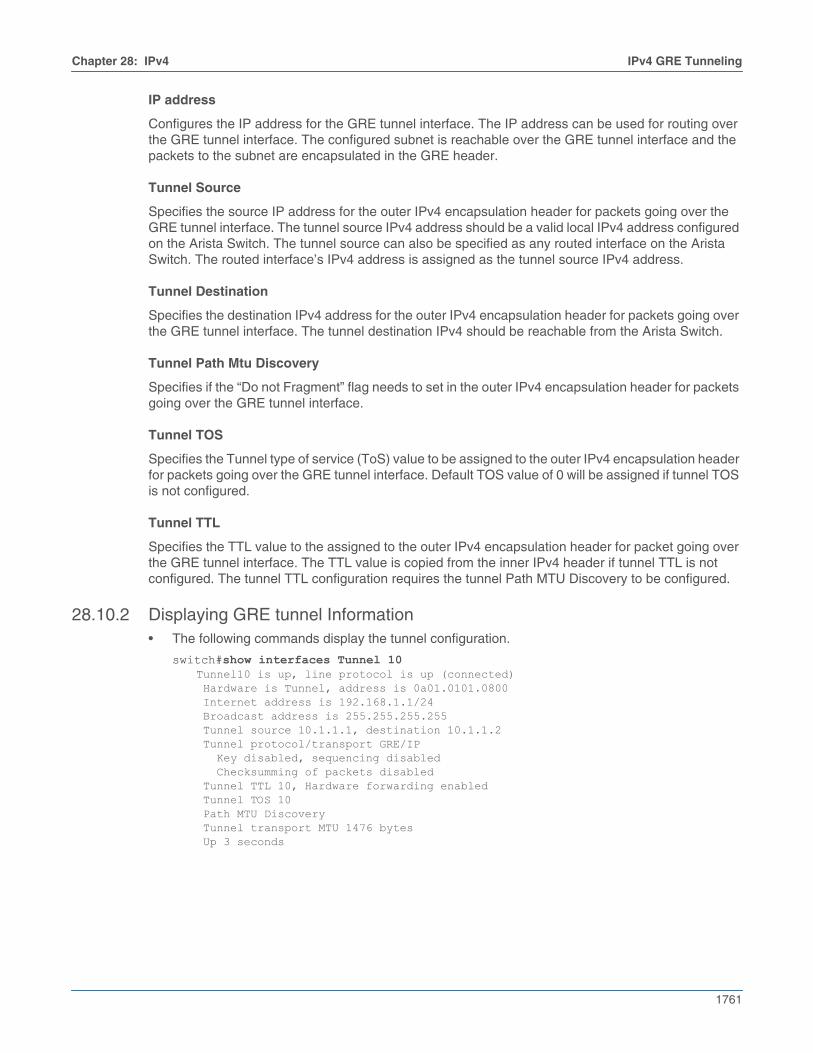
Chapter 28: IPv4 IPv4 GRE Tunneling
1761
IP address
Configures the IP address for the GRE tunnel interface. The IP address can be used for routing overthe GRE tunnel interface. The configured subnet is reachable over the GRE tunnel interface and thepackets to the subnet are encapsulated in the GRE header.
Tunnel Source
Specifies the source IP address for the outer IPv4 encapsulation header for packets going over theGRE tunnel interface. The tunnel source IPv4 address should be a valid local IPv4 address configuredon the Arista Switch. The tunnel source can also be specified as any routed interface on the AristaSwitch. The routed interface’s IPv4 address is assigned as the tunnel source IPv4 address.
Tunnel Destination
Specifies the destination IPv4 address for the outer IPv4 encapsulation header for packets going overthe GRE tunnel interface. The tunnel destination IPv4 should be reachable from the Arista Switch.
Tunnel Path Mtu Discovery
Specifies if the “Do not Fragment” flag needs to set in the outer IPv4 encapsulation header for packetsgoing over the GRE tunnel interface.
Tunnel TOS
Specifies the Tunnel type of service (ToS) value to be assigned to the outer IPv4 encapsulation headerfor packets going over the GRE tunnel interface. Default TOS value of 0 will be assigned if tunnel TOSis not configured.
Tunnel TTL
Specifies the TTL value to the assigned to the outer IPv4 encapsulation header for packet going overthe GRE tunnel interface. The TTL value is copied from the inner IPv4 header if tunnel TTL is notconfigured. The tunnel TTL configuration requires the tunnel Path MTU Discovery to be configured.
28.10.2 Displaying GRE tunnel Information• The following commands display the tunnel configuration.
switch#show interfaces Tunnel 10Tunnel10 is up, line protocol is up (connected) Hardware is Tunnel, address is 0a01.0101.0800 Internet address is 192.168.1.1/24 Broadcast address is 255.255.255.255 Tunnel source 10.1.1.1, destination 10.1.1.2 Tunnel protocol/transport GRE/IP Key disabled, sequencing disabled Checksumming of packets disabled Tunnel TTL 10, Hardware forwarding enabled Tunnel TOS 10 Path MTU Discovery Tunnel transport MTU 1476 bytes Up 3 seconds

1762
IPv4 GRE Tunneling Chapter 28: IPv4
switch#show gre tunnel staticName Index Source Destination Nexthop Interface----------- ------- -------------- ----------------- -------------- -----------Tunnel10 10 10.1.1.1 10.1.1.2 10.6.1.2 Ethernet6/1
switch#show tunnel fib static interface gre 10Type 'Static Interface', index 10, forwarding Primary via 10.6.1.2, 'Ethernet6/1' GRE, destination 10.1.1.2, source 10.1.1.1, ttl 10, tos 0xa
• Use show platform fap tcam summary to verify if the TCAM bank is allocated for GRE packettermination lookup.
switch#show platform fap tcam summary
Tcam Allocation (Jericho0) Bank Used By Reserved By---------- ------------------------- ----------- 0 dbGreTunnel -
• Use show ip route to verify if the routes over tunnel is setup properly.
switch#show ip route
VRF: defaultCodes: C - connected, S - static, K - kernel, O - OSPF, IA - OSPF inter area, E1 - OSPF external type 1, E2 - OSPF external type 2, N1 - OSPF NSSA external type 1, N2 - OSPF NSSA external type2, B I - iBGP, B E - eBGP, R - RIP, I L1 - IS-IS level 1, I L2 - IS-IS level 2, O3 - OSPFv3, A B - BGP Aggregate, A O - OSPF Summary, NG - Nexthop Group Static Route, V - VXLAN Control Service, DH - DHCP client installed default route, M - Martian, DP - Dynamic Policy Route
Gateway of last resort is not set
C 192.168.1.0/24 is directly connected, Tunnel10, Static Interface GRE tunnel index 10, dst 10.1.1.2, src 10.1.1.1, TTL 10, TOS 10 S 192.168.100.0/24 is directly connected, Tunnel10, Static Interface GRE tunnel index 10, dst 10.1.1.2, src 10.1.1.1, TTL 10, TOS 10
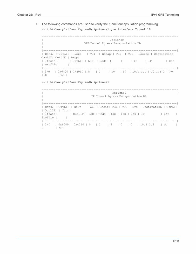
Chapter 28: IPv4 IPv4 GRE Tunneling
1763
• The following commands are used to verify the tunnel encapsulation programming.
switch#show platform fap eedb ip-tunnel gre interface Tunnel 10 -------------------------------------------------------------------------------| Jericho0 || GRE Tunnel Egress Encapsulation DB ||-----------------------------------------------------------------------------|| Bank/ | OutLIF | Next | VSI | Encap | TOS | TTL | Source | Destination| OamLIF| OutLIF | Drop|| Offset| | OutLIF | LSB | Mode | | | IP | IP | Set | Profile| ||-----------------------------------------------------------------------------|| 3/0 | 0x6000 | 0x4010 | 0 | 2 | 10 | 10 | 10.1.1.1 | 10.1.1.2 | No | 0 | No |
switch#show platform fap eedb ip-tunnel -------------------------------------------------------------------------------| Jericho0 || IP Tunnel Egress Encapsulation DB ||-----------------------------------------------------------------------------|| Bank/ | OutLIF | Next | VSI | Encap| TOS | TTL | Src | Destination | OamLIF | OutLIF | Drop|| Offset| | OutLIF | LSB | Mode | Idx | Idx | Idx | IP | Set | Profile | ||-----------------------------------------------------------------------------|| 3/0 | 0x6000 | 0x4010 | 0 | 2 | 9 | 0 | 0 | 10.1.1.2 | No | 0 | No |
1764
IPv4 Commands Chapter 28: IPv4
28.11 IPv4 CommandsIP Routing and Address Commands• agent SandL3Unicast terminate• clear arp inspection statistics• ip address• ip arp inspection limit• ip arp inspection logging• ip arp inspection trust• ip arp inspection vlan• ip hardware fib ecmp resilience• ip hardware fib optimize• ip icmp redirect• ip load-sharing• ip route• ip routing• ip source binding• ip verify• ip verify source• rib fib policy• show ip• show ip arp inspection vlan• show ip arp inspection statistics• show ip interface• show ip interface brief• show ip route• show ip route age• show ip route gateway• show ip route host• show ip route match tag• show ip route summary• show rib route ip• show rib route <ipv4 | ipv6> fib policy excluded• show routing-context vrf• show vrf• show ip verify source• show platform arad ip route• show platform arad ip route summary• tcp mss ceiling
IPv4 DHCP Relay• clear ip dhcp relay counters• ip dhcp relay all-subnets• ip dhcp relay all-subnets default• ip dhcp relay always-on• ip dhcp relay information option (Global)• ip dhcp relay information option circuit-id• ip helper-address• show ip dhcp relay• show ip dhcp relay counters
Chapter 28: IPv4 IPv4 Commands
1765
IPv4 DHCP Snooping• clear ip dhcp snooping counters• ip dhcp snooping• ip dhcp snooping information option• ip dhcp snooping vlan• show ip dhcp snooping• show ip dhcp snooping counters• show ip dhcp snooping hardware
IPv4 Multicast Counters• clear ip multicast count• ip multicast count
IPv4 NAT• clear ip nat flow translation• ip nat destination static• ip nat pool• ip nat source dynamic• ip nat source static• ip nat translation counters• ip nat translation low-mark• ip nat translation max-entries• ip nat translation tcp-timeout• ip nat translation udp-timeout• show ip nat access-list interface• show ip nat pool• show ip nat translation• show ip nat synchronization peer• show ip nat synchronization advertised-translations• show ip nat synchronization discovered-translations
ARP Table• arp• arp aging timeout• arp cache persistent• arp gratuitous accept• clear arp-cache• clear arp• ip local-proxy-arp• ip proxy-arp• show arp• show ip arp
VRF Commands• cli vrf• description (VRF)• rd (VRF configuration mode)• show routing-context vrf• show vrf• vrf (Interface mode)• vrf instance
1766
IPv4 Commands Chapter 28: IPv4
Trident Forwarding Table Commands• platform trident forwarding-table partition• platform trident routing-table partition• show platform trident forwarding-table partition
IPv4 GRE Tunneling Commands• interface tunnel• tunnel• show interface tunnel• show platform fap eedb ip-tunnel gre interface tunnel• show tunnel fib static interface gre• show platform fap tcam summary
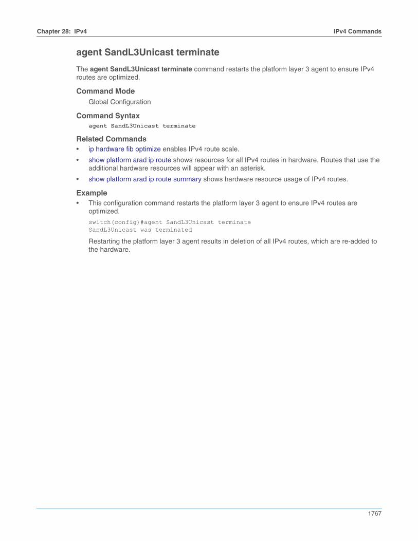
Chapter 28: IPv4 IPv4 Commands
1767
agent SandL3Unicast terminate
The agent SandL3Unicast terminate command restarts the platform layer 3 agent to ensure IPv4routes are optimized.
Command ModeGlobal Configuration
Command Syntaxagent SandL3Unicast terminate
Related Commands• ip hardware fib optimize enables IPv4 route scale.
• show platform arad ip route shows resources for all IPv4 routes in hardware. Routes that use theadditional hardware resources will appear with an asterisk.
• show platform arad ip route summary shows hardware resource usage of IPv4 routes.
Example• This configuration command restarts the platform layer 3 agent to ensure IPv4 routes are
optimized.
switch(config)#agent SandL3Unicast terminateSandL3Unicast was terminated
Restarting the platform layer 3 agent results in deletion of all IPv4 routes, which are re-added tothe hardware.
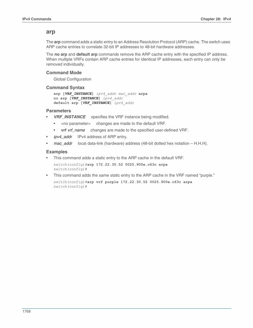
1768
IPv4 Commands Chapter 28: IPv4
arp
The arp command adds a static entry to an Address Resolution Protocol (ARP) cache. The switch usesARP cache entries to correlate 32-bit IP addresses to 48-bit hardware addresses.
The no arp and default arp commands remove the ARP cache entry with the specified IP address.When multiple VRFs contain ARP cache entries for identical IP addresses, each entry can only beremoved individually.
Command ModeGlobal Configuration
Command Syntaxarp [VRF_INSTANCE] ipv4_addr mac_addr arpano arp [VRF_INSTANCE] ipv4_addrdefault arp [VRF_INSTANCE] ipv4_addr
Parameters• VRF_INSTANCE specifies the VRF instance being modified.
• <no parameter> changes are made to the default VRF.
• vrf vrf_name changes are made to the specified user-defined VRF.
• ipv4_addr IPv4 address of ARP entry.
• mac_addr local data-link (hardware) address (48-bit dotted hex notation – H.H.H).
Examples• This command adds a static entry to the ARP cache in the default VRF.
switch(config)#arp 172.22.30.52 0025.900e.c63c arpaswitch(config)#
• This command adds the same static entry to the ARP cache in the VRF named “purple.”
switch(config)#arp vrf purple 172.22.30.52 0025.900e.c63c arpaswitch(config)#
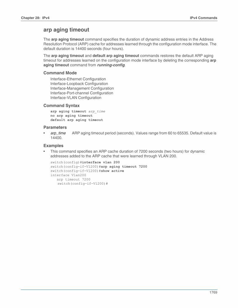
Chapter 28: IPv4 IPv4 Commands
1769
arp aging timeout
The arp aging timeout command specifies the duration of dynamic address entries in the AddressResolution Protocol (ARP) cache for addresses learned through the configuration mode interface. Thedefault duration is 14400 seconds (four hours).
The arp aging timeout and default arp aging timeout commands restores the default ARP agingtimeout for addresses learned on the configuration mode interface by deleting the corresponding arpaging timeout command from running-config.
Command ModeInterface-Ethernet ConfigurationInterface-Loopback ConfigurationInterface-Management ConfigurationInterface-Port-channel ConfigurationInterface-VLAN Configuration
Command Syntaxarp aging timeout arp_timeno arp aging timeoutdefault arp aging timeout
Parameters• arp_time ARP aging timeout period (seconds). Values range from 60 to 65535. Default value is
14400.
Examples• This command specifies an ARP cache duration of 7200 seconds (two hours) for dynamic
addresses added to the ARP cache that were learned through VLAN 200.
switch(config)#interface vlan 200switch(config-if-Vl200)#arp aging timeout 7200switch(config-if-Vl200)#show activeinterface Vlan200 arp timeout 7200
switch(config-if-Vl200)#
1770
IPv4 Commands Chapter 28: IPv4
arp cache persistent
The arp cache persistent command restores the dynamic entries in the Address Resolution Protocol(ARP) cache after reboot.
The no arp cache persistent and default arp cache persistent commands remove the ARP cachepersistent configuration from the running-config.
Command ModeGlobal Configuration
Command Syntaxarp cache persistentno arp cache persistentdefault arp cache persistent
Example• This command restores the ARP cache after reboot.
switch(config)#arp cache persistentswitch(config)#
Chapter 28: IPv4 IPv4 Commands
1771
arp gratuitous accept
The arp gratuitous accept command configures the configuration mode interface to accept gratuitousARP request packets received on that interface. Accepted gratuitous ARP requests are then learnedby the ARP table.
The no and default forms of the command prevent the interface from accepting gratuitous ARPrequests. Configuring gratuitous ARP acceptance on an L2 interface has no effect.
Command ModeInterface-Ethernet ConfigurationInterface-VLAN ConfigurationInterface Port-channel Configuration
Command Syntaxarp gratuitous acceptno arp gratuitous acceptdefault arp gratuitous accept
Example• These commands configure Ethernet interface 2/1 to accept gratuitous ARP request packets.
switch (config)# interface ethernet 2/1switch (config-if-Et2/1)#arp gratuitous acceptswitch (config-if-Et2/1)#
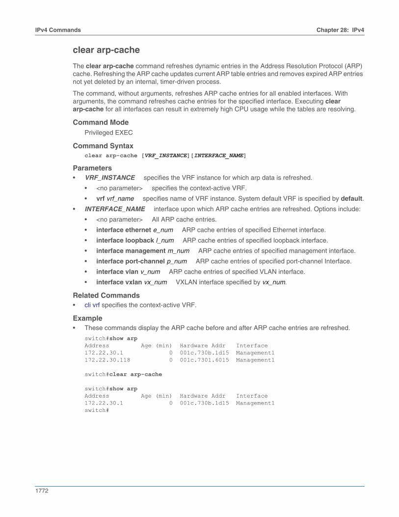
1772
IPv4 Commands Chapter 28: IPv4
clear arp-cache
The clear arp-cache command refreshes dynamic entries in the Address Resolution Protocol (ARP)cache. Refreshing the ARP cache updates current ARP table entries and removes expired ARP entriesnot yet deleted by an internal, timer-driven process.
The command, without arguments, refreshes ARP cache entries for all enabled interfaces. Witharguments, the command refreshes cache entries for the specified interface. Executing cleararp-cache for all interfaces can result in extremely high CPU usage while the tables are resolving.
Command ModePrivileged EXEC
Command Syntaxclear arp-cache [VRF_INSTANCE][INTERFACE_NAME]
Parameters• VRF_INSTANCE specifies the VRF instance for which arp data is refreshed.
• <no parameter> specifies the context-active VRF.
• vrf vrf_name specifies name of VRF instance. System default VRF is specified by default.
• INTERFACE_NAME interface upon which ARP cache entries are refreshed. Options include:
• <no parameter> All ARP cache entries.
• interface ethernet e_num ARP cache entries of specified Ethernet interface.
• interface loopback l_num ARP cache entries of specified loopback interface.
• interface management m_num ARP cache entries of specified management interface.
• interface port-channel p_num ARP cache entries of specified port-channel Interface.
• interface vlan v_num ARP cache entries of specified VLAN interface.
• interface vxlan vx_num VXLAN interface specified by vx_num.
Related Commands• cli vrf specifies the context-active VRF.
Example• These commands display the ARP cache before and after ARP cache entries are refreshed.
switch#show arpAddress Age (min) Hardware Addr Interface172.22.30.1 0 001c.730b.1d15 Management1172.22.30.118 0 001c.7301.6015 Management1
switch#clear arp-cache
switch#show arpAddress Age (min) Hardware Addr Interface172.22.30.1 0 001c.730b.1d15 Management1switch#
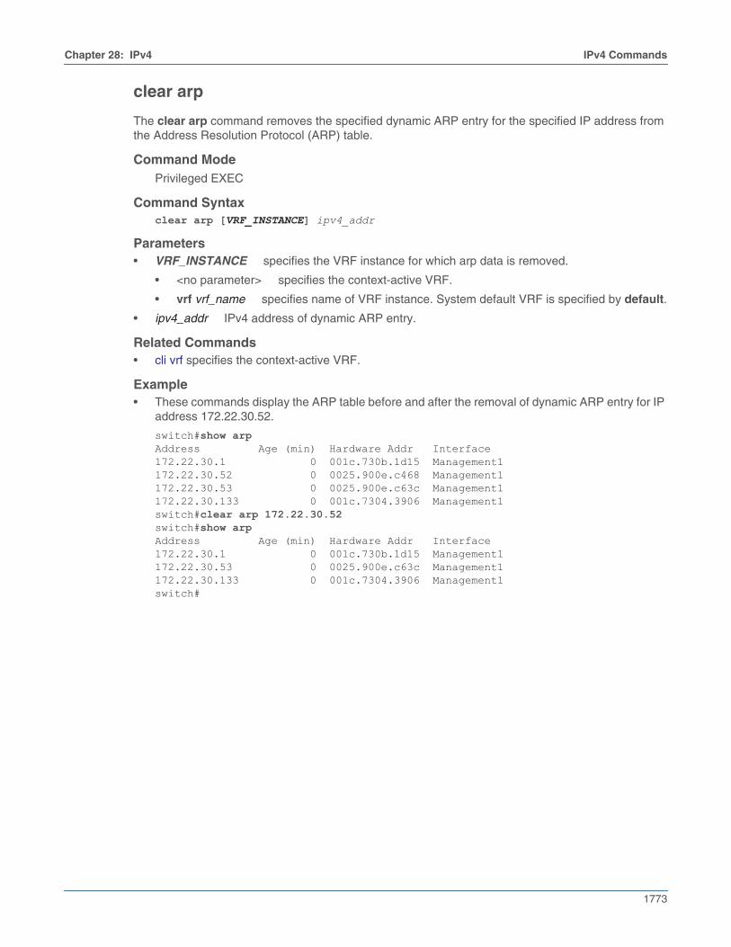
Chapter 28: IPv4 IPv4 Commands
1773
clear arp
The clear arp command removes the specified dynamic ARP entry for the specified IP address fromthe Address Resolution Protocol (ARP) table.
Command ModePrivileged EXEC
Command Syntaxclear arp [VRF_INSTANCE] ipv4_addr
Parameters• VRF_INSTANCE specifies the VRF instance for which arp data is removed.
• <no parameter> specifies the context-active VRF.
• vrf vrf_name specifies name of VRF instance. System default VRF is specified by default.
• ipv4_addr IPv4 address of dynamic ARP entry.
Related Commands• cli vrf specifies the context-active VRF.
Example• These commands display the ARP table before and after the removal of dynamic ARP entry for IP
address 172.22.30.52.
switch#show arpAddress Age (min) Hardware Addr Interface172.22.30.1 0 001c.730b.1d15 Management1172.22.30.52 0 0025.900e.c468 Management1172.22.30.53 0 0025.900e.c63c Management1172.22.30.133 0 001c.7304.3906 Management1switch#clear arp 172.22.30.52switch#show arpAddress Age (min) Hardware Addr Interface172.22.30.1 0 001c.730b.1d15 Management1172.22.30.53 0 0025.900e.c63c Management1172.22.30.133 0 001c.7304.3906 Management1switch#
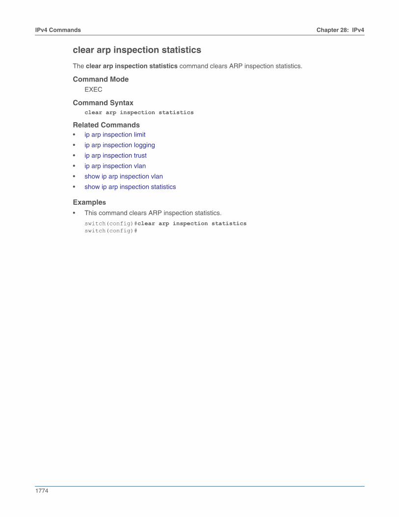
1774
IPv4 Commands Chapter 28: IPv4
clear arp inspection statistics
The clear arp inspection statistics command clears ARP inspection statistics.
Command ModeEXEC
Command Syntaxclear arp inspection statistics
Related Commands• ip arp inspection limit
• ip arp inspection logging
• ip arp inspection trust
• ip arp inspection vlan
• show ip arp inspection vlan
• show ip arp inspection statistics
Examples
• This command clears ARP inspection statistics.
switch(config)#clear arp inspection statisticsswitch(config)#
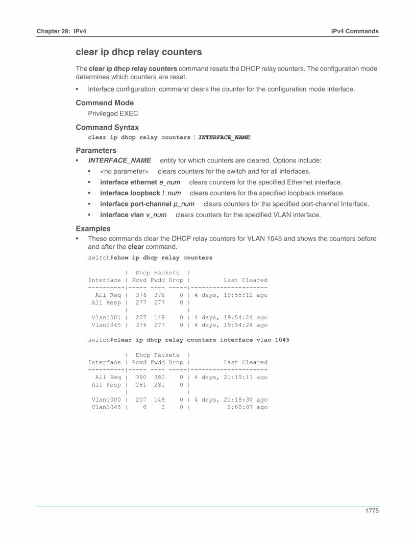
Chapter 28: IPv4 IPv4 Commands
1775
clear ip dhcp relay counters
The clear ip dhcp relay counters command resets the DHCP relay counters. The configuration modedetermines which counters are reset:
• Interface configuration: command clears the counter for the configuration mode interface.
Command ModePrivileged EXEC
Command Syntaxclear ip dhcp relay counters [INTERFACE_NAME]
Parameters• INTERFACE_NAME entity for which counters are cleared. Options include:
• <no parameter> clears counters for the switch and for all interfaces.
• interface ethernet e_num clears counters for the specified Ethernet interface.
• interface loopback l_num clears counters for the specified loopback interface.
• interface port-channel p_num clears counters for the specified port-channel Interface.
• interface vlan v_num clears counters for the specified VLAN interface.
Examples• These commands clear the DHCP relay counters for VLAN 1045 and shows the counters before
and after the clear command.
switch#show ip dhcp relay counters
| Dhcp Packets |Interface | Rcvd Fwdd Drop | Last Cleared----------|----- ---- -----|--------------------- All Req | 376 376 0 | 4 days, 19:55:12 ago All Resp | 277 277 0 | | | Vlan1001 | 207 148 0 | 4 days, 19:54:24 ago Vlan1045 | 376 277 0 | 4 days, 19:54:24 ago
switch#clear ip dhcp relay counters interface vlan 1045
| Dhcp Packets |Interface | Rcvd Fwdd Drop | Last Cleared----------|----- ---- -----|--------------------- All Req | 380 380 0 | 4 days, 21:19:17 ago All Resp | 281 281 0 | | | Vlan1000 | 207 148 0 | 4 days, 21:18:30 ago Vlan1045 | 0 0 0 | 0:00:07 ago
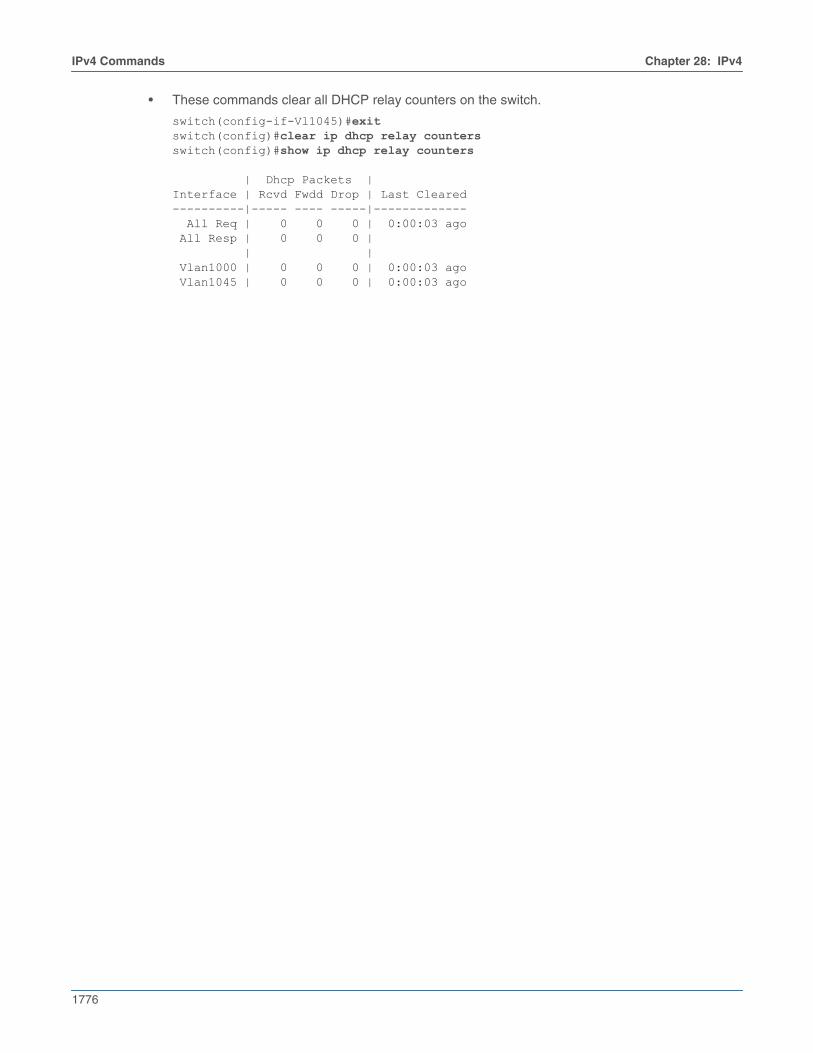
1776
IPv4 Commands Chapter 28: IPv4
• These commands clear all DHCP relay counters on the switch.
switch(config-if-Vl1045)#exitswitch(config)#clear ip dhcp relay countersswitch(config)#show ip dhcp relay counters
| Dhcp Packets |Interface | Rcvd Fwdd Drop | Last Cleared----------|----- ---- -----|------------- All Req | 0 0 0 | 0:00:03 ago All Resp | 0 0 0 | | | Vlan1000 | 0 0 0 | 0:00:03 ago Vlan1045 | 0 0 0 | 0:00:03 ago
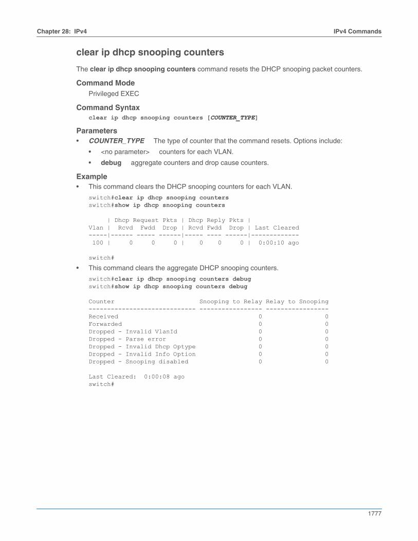
Chapter 28: IPv4 IPv4 Commands
1777
clear ip dhcp snooping counters
The clear ip dhcp snooping counters command resets the DHCP snooping packet counters.
Command ModePrivileged EXEC
Command Syntaxclear ip dhcp snooping counters [COUNTER_TYPE]
Parameters• COUNTER_TYPE The type of counter that the command resets. Options include:
• <no parameter> counters for each VLAN.
• debug aggregate counters and drop cause counters.
Example• This command clears the DHCP snooping counters for each VLAN.
switch#clear ip dhcp snooping countersswitch#show ip dhcp snooping counters
| Dhcp Request Pkts | Dhcp Reply Pkts |Vlan | Rcvd Fwdd Drop | Rcvd Fwdd Drop | Last Cleared-----|------ ----- ------|----- ---- ------|------------- 100 | 0 0 0 | 0 0 0 | 0:00:10 ago
switch#
• This command clears the aggregate DHCP snooping counters.
switch#clear ip dhcp snooping counters debugswitch#show ip dhcp snooping counters debug
Counter Snooping to Relay Relay to Snooping----------------------------- ----------------- -----------------Received 0 0Forwarded 0 0Dropped - Invalid VlanId 0 0Dropped - Parse error 0 0Dropped - Invalid Dhcp Optype 0 0Dropped - Invalid Info Option 0 0Dropped - Snooping disabled 0 0
Last Cleared: 0:00:08 agoswitch#

1778
IPv4 Commands Chapter 28: IPv4
clear ip multicast count
The clear ip multicast count command clears all counters associated with the multicast traffic.
Command ModeGobal Configuration
Command Syntaxclear ip multicast count [group_address [source_address]]
Parameters• <no parameters> clears all counts of the multicast route traffic
• group_address clears the multicast traffic count of the specified group address
• source_address clears the multicast traffic count of the specified group and sourceaddresses
Guidelines• This command functions only when the ip multicast count command is enabled.
Examples• This command clears all counters associated with the multicast traffic.
switch(config)#clear ip multicast count
• This command clears the multicast traffic count of the specified group address.
switch(config)#clear ip multicast count 16.39.24.233
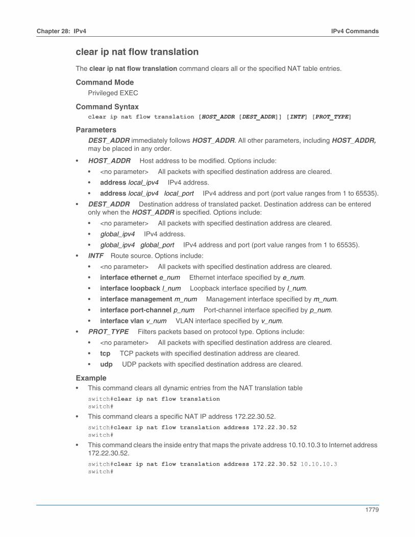
Chapter 28: IPv4 IPv4 Commands
1779
clear ip nat flow translation
The clear ip nat flow translation command clears all or the specified NAT table entries.
Command ModePrivileged EXEC
Command Syntaxclear ip nat flow translation [HOST_ADDR [DEST_ADDR]] [INTF] [PROT_TYPE]
ParametersDEST_ADDR immediately follows HOST_ADDR. All other parameters, including HOST_ADDR,may be placed in any order.
• HOST_ADDR Host address to be modified. Options include:
• <no parameter> All packets with specified destination address are cleared.
• address local_ipv4 IPv4 address.
• address local_ipv4 local_port IPv4 address and port (port value ranges from 1 to 65535).
• DEST_ADDR Destination address of translated packet. Destination address can be enteredonly when the HOST_ADDR is specified. Options include:
• <no parameter> All packets with specified destination address are cleared.
• global_ipv4 IPv4 address.
• global_ipv4 global_port IPv4 address and port (port value ranges from 1 to 65535).
• INTF Route source. Options include:
• <no parameter> All packets with specified destination address are cleared.
• interface ethernet e_num Ethernet interface specified by e_num.
• interface loopback l_num Loopback interface specified by l_num.
• interface management m_num Management interface specified by m_num.
• interface port-channel p_num Port-channel interface specified by p_num.
• interface vlan v_num VLAN interface specified by v_num.
• PROT_TYPE Filters packets based on protocol type. Options include:
• <no parameter> All packets with specified destination address are cleared.
• tcp TCP packets with specified destination address are cleared.
• udp UDP packets with specified destination address are cleared.
Example• This command clears all dynamic entries from the NAT translation table
switch#clear ip nat flow translationswitch#
• This command clears a specific NAT IP address 172.22.30.52.
switch#clear ip nat flow translation address 172.22.30.52switch#
• This command clears the inside entry that maps the private address 10.10.10.3 to Internet address172.22.30.52.
switch#clear ip nat flow translation address 172.22.30.52 10.10.10.3switch#
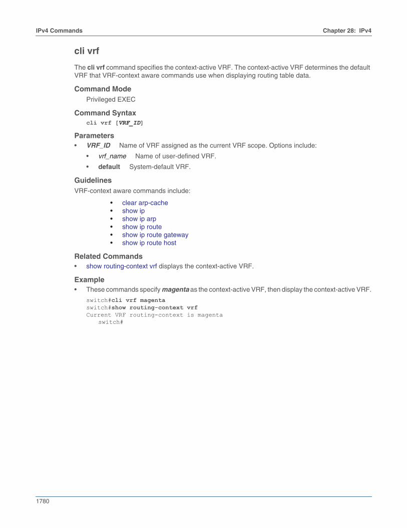
1780
IPv4 Commands Chapter 28: IPv4
cli vrf
The cli vrf command specifies the context-active VRF. The context-active VRF determines the defaultVRF that VRF-context aware commands use when displaying routing table data.
Command ModePrivileged EXEC
Command Syntaxcli vrf [VRF_ID]
Parameters• VRF_ID Name of VRF assigned as the current VRF scope. Options include:
• vrf_name Name of user-defined VRF.
• default System-default VRF.
GuidelinesVRF-context aware commands include:
• clear arp-cache• show ip• show ip arp• show ip route• show ip route gateway• show ip route host
Related Commands• show routing-context vrf displays the context-active VRF.
Example• These commands specify magenta as the context-active VRF, then display the context-active VRF.
switch#cli vrf magentaswitch#show routing-context vrfCurrent VRF routing-context is magenta
switch#

Chapter 28: IPv4 IPv4 Commands
1781
description (VRF)
The description command adds a text string to the configuration mode VRF. The string has nofunctional impact on the VRF.
The no description and default description commands remove the text string from the configurationmode VRF by deleting the corresponding description command from running-config.
Command ModeVRF Configuration
Command Syntaxdescription label_textno descriptiondefault description
Parameters• label_text character string assigned to the VRF configuration.
Related Commands• vrf instance places the switch in VRF configuration mode.
Examples• These commands add description text to the magenta VRF.
switch(config)#vrf instance magentaswitch(config-vrf-magenta)#description This is the first vrfswitch(config-vrf-magenta)#show active vrf instance magenta description This is the first vrfswitch(config-vrf-magenta)#
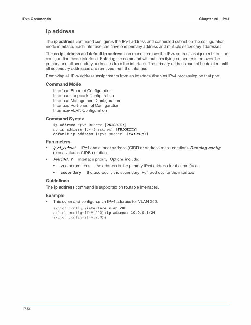
1782
IPv4 Commands Chapter 28: IPv4
ip address
The ip address command configures the IPv4 address and connected subnet on the configurationmode interface. Each interface can have one primary address and multiple secondary addresses.
The no ip address and default ip address commands remove the IPv4 address assignment from theconfiguration mode interface. Entering the command without specifying an address removes theprimary and all secondary addresses from the interface. The primary address cannot be deleted untilall secondary addresses are removed from the interface.
Removing all IPv4 address assignments from an interface disables IPv4 processing on that port.
Command ModeInterface-Ethernet ConfigurationInterface-Loopback ConfigurationInterface-Management ConfigurationInterface-Port-channel ConfigurationInterface-VLAN Configuration
Command Syntaxip address ipv4_subnet [PRIORITY]no ip address [ipv4_subnet] [PRIORITY]default ip address [ipv4_subnet] [PRIORITY]
Parameters• ipv4_subnet IPv4 and subnet address (CIDR or address-mask notation). Running-config
stores value in CIDR notation.
• PRIORITY interface priority. Options include:
• <no parameter> the address is the primary IPv4 address for the interface.
• secondary the address is the secondary IPv4 address for the interface.
GuidelinesThe ip address command is supported on routable interfaces.
Example• This command configures an IPv4 address for VLAN 200.
switch(config)#interface vlan 200switch(config-if-Vl200)#ip address 10.0.0.1/24switch(config-if-Vl200)#
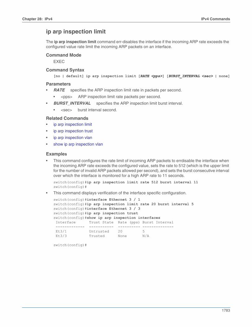
Chapter 28: IPv4 IPv4 Commands
1783
ip arp inspection limit
The ip arp inspection limit command err-disables the interface if the incoming ARP rate exceeds theconfigured value rate limit the incoming ARP packets on an interface.
Command ModeEXEC
Command Syntax[no | default] ip arp inspection limit [RATE <pps>] [BURST_INTERVAL <sec> | none]
Parameters• RATE specifies the ARP inspection limit rate in packets per second.
• <pps> ARP inspection limit rate packets per second.
• BURST_INTERVAL specifies the ARP inspection limit burst interval.
• <sec> burst interval second.
Related Commands• ip arp inspection limit
• ip arp inspection trust
• ip arp inspection vlan
• show ip arp inspection vlan
Examples
• This command configures the rate limit of incoming ARP packets to errdisable the interface whenthe incoming ARP rate exceeds the configured value, sets the rate to 512 (which is the upper limitfor the number of invalid ARP packets allowed per second), and sets the burst consecutive intervalover which the interface is monitored for a high ARP rate to 11 seconds.
switch(config)#ip arp inspection limit rate 512 burst interval 11switch(config)#
• This command displays verification of the interface specific configuration.
switch(config)#interface Ethernet 3 / 1switch(config)#ip arp inspection limit rate 20 burst interval 5switch(config)#interface Ethernet 3 / 3switch(config)#ip arp inspection trustswitch(config)#show ip arp inspection interfaces Interface Trust State Rate (pps) Burst Interval ------------- ----------- ---------- -------------- Et3/1 Untrusted 20 5 Et3/3 Trusted None N/A
switch(config)#
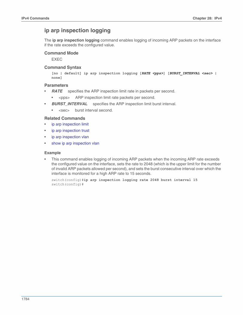
1784
IPv4 Commands Chapter 28: IPv4
ip arp inspection logging
The ip arp inspection logging command enables logging of incoming ARP packets on the interfaceif the rate exceeds the configured value.
Command ModeEXEC
Command Syntax[no | default] ip arp inspection logging [RATE <pps>] [BURST_INTERVAL <sec> | none]
Parameters• RATE specifies the ARP inspection limit rate in packets per second.
• <pps> ARP inspection limit rate packets per second.
• BURST_INTERVAL specifies the ARP inspection limit burst interval.
• <sec> burst interval second.
Related Commands• ip arp inspection limit
• ip arp inspection trust
• ip arp inspection vlan
• show ip arp inspection vlan
Example
• This command enables logging of incoming ARP packets when the incoming ARP rate exceedsthe configured value on the interface, sets the rate to 2048 (which is the upper limit for the numberof invalid ARP packets allowed per second), and sets the burst consecutive interval over which theinterface is monitored for a high ARP rate to 15 seconds.
switch(config)#ip arp inspection logging rate 2048 burst interval 15switch(config)#
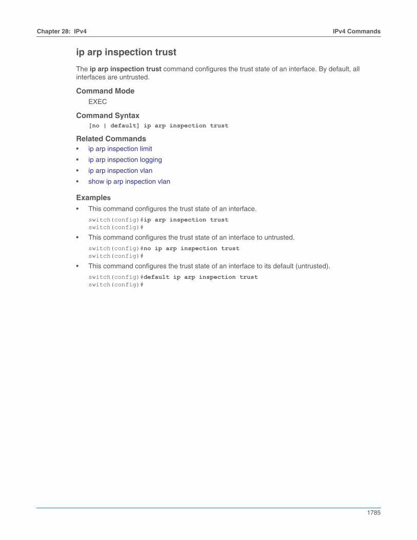
Chapter 28: IPv4 IPv4 Commands
1785
ip arp inspection trust
The ip arp inspection trust command configures the trust state of an interface. By default, allinterfaces are untrusted.
Command ModeEXEC
Command Syntax[no | default] ip arp inspection trust
Related Commands• ip arp inspection limit
• ip arp inspection logging
• ip arp inspection vlan
• show ip arp inspection vlan
Examples
• This command configures the trust state of an interface.
switch(config)#ip arp inspection trustswitch(config)#
• This command configures the trust state of an interface to untrusted.
switch(config)#no ip arp inspection trustswitch(config)#
• This command configures the trust state of an interface to its default (untrusted).
switch(config)#default ip arp inspection trustswitch(config)#

1786
IPv4 Commands Chapter 28: IPv4
ip arp inspection vlan
The ip arp inspection vlan command enables ARP inspection. ARP requests and responses onuntrusted interfaces are intercepted on specified VLANs, and intercepted packets are verified to havevalid IP-MAC address bindings. All invalid ARP packets are dropped. On trusted interfaces, allincoming ARP packets are processed and forwarded without verification. By default, ARP inspection isdisabled on all VLANs.
Command ModeEXEC
Command Syntaxip arp inspection vlan [LIST]
Parameters• LIST specifies the VLAN interface number.
Related Commands• ip arp inspection limit
• ip arp inspection trust
• show ip arp inspection vlan
Examples
• This command enables ARP inspection on VLANs 1 through 150.
switch(config)#ip arp inspection vlan 1 - 150switch(config)#
• This command disables ARP inspection on VLANs 1 through 150.
switch(config)#no ip arp inspection vlan 1 - 150switch(config)#
• This command sets the ARP inspection default to VLANs 1 through 150.
switch(config)#default ip arp inspection vlan 1 - 150switch(config)#
• These commands enable ARP inspection on multiple VLANs 1 through 150 and 200 through 250.
switch(config)#ip arp inspection vlan 1-150,200-250switch(config)#
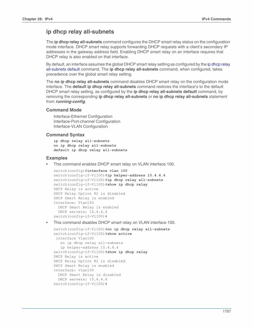
Chapter 28: IPv4 IPv4 Commands
1787
ip dhcp relay all-subnets
The ip dhcp relay all-subnets command configures the DHCP smart relay status on the configurationmode interface. DHCP smart relay supports forwarding DHCP requests with a client’s secondary IPaddresses in the gateway address field. Enabling DHCP smart relay on an interface requires thatDHCP relay is also enabled on that interface.
By default, an interface assumes the global DHCP smart relay setting as configured by the ip dhcp relayall-subnets default command. The ip dhcp relay all-subnets command, when configured, takesprecedence over the global smart relay setting.
The no ip dhcp relay all-subnets command disables DHCP smart relay on the configuration modeinterface. The default ip dhcp relay all-subnets command restores the interface’s to the defaultDHCP smart relay setting, as configured by the ip dhcp relay all-subnets default command, byremoving the corresponding ip dhcp relay all-subnets or no ip dhcp relay all-subnets statementfrom running-config.
Command ModeInterface-Ethernet ConfigurationInterface-Port-channel ConfigurationInterface-VLAN Configuration
Command Syntaxip dhcp relay all-subnetsno ip dhcp relay all-subnetsdefault ip dhcp relay all-subnets
Examples• This command enables DHCP smart relay on VLAN interface 100.
switch(config)#interface vlan 100switch(config-if-Vl100)#ip helper-address 10.4.4.4switch(config-if-Vl100)#ip dhcp relay all-subnetsswitch(config-if-Vl100)#show ip dhcp relayDHCP Relay is activeDHCP Relay Option 82 is disabledDHCP Smart Relay is enabledInterface: Vlan100 DHCP Smart Relay is enabled DHCP servers: 10.4.4.4switch(config-if-Vl100)#
• This command disables DHCP smart relay on VLAN interface 100.
switch(config-if-Vl100)#no ip dhcp relay all-subnetsswitch(config-if-Vl100)#show active interface Vlan100 no ip dhcp relay all-subnets ip helper-address 10.4.4.4switch(config-if-Vl100)#show ip dhcp relayDHCP Relay is activeDHCP Relay Option 82 is disabledDHCP Smart Relay is enabledInterface: Vlan100 DHCP Smart Relay is disabled DHCP servers: 10.4.4.4switch(config-if-Vl100)#
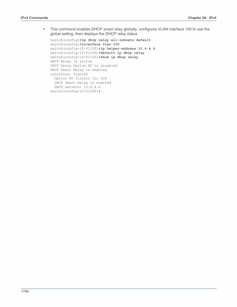
1788
IPv4 Commands Chapter 28: IPv4
• This command enables DHCP smart relay globally, configures VLAN interface 100 to use theglobal setting, then displays the DHCP relay status
switch(config)#ip dhcp relay all-subnets defaultswitch(config)#interface vlan 100switch(config-if-Vl100)#ip helper-address 10.4.4.4switch(config-if-Vl100)#default ip dhcp relayswitch(config-if-Vl100)#show ip dhcp relayDHCP Relay is activeDHCP Relay Option 82 is disabledDHCP Smart Relay is enabledInterface: Vlan100 Option 82 Circuit ID: 333 DHCP Smart Relay is enabled DHCP servers: 10.4.4.4switch(config-if-Vl100)#
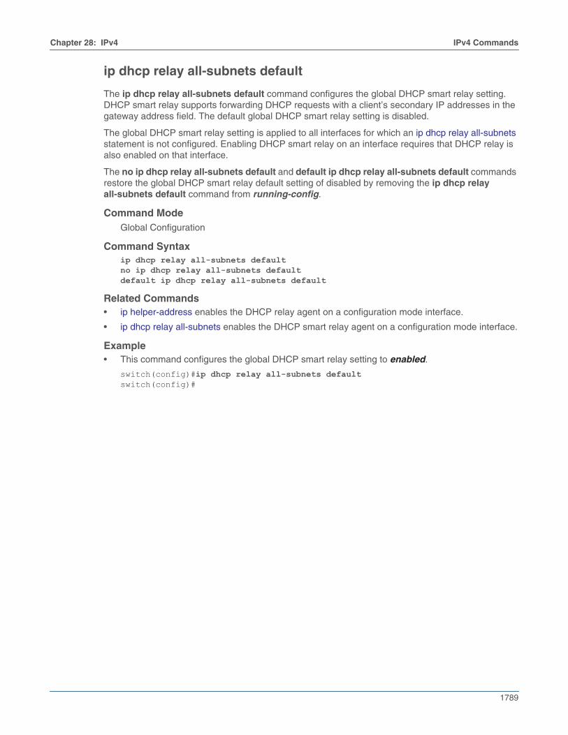
Chapter 28: IPv4 IPv4 Commands
1789
ip dhcp relay all-subnets default
The ip dhcp relay all-subnets default command configures the global DHCP smart relay setting.DHCP smart relay supports forwarding DHCP requests with a client’s secondary IP addresses in thegateway address field. The default global DHCP smart relay setting is disabled.
The global DHCP smart relay setting is applied to all interfaces for which an ip dhcp relay all-subnetsstatement is not configured. Enabling DHCP smart relay on an interface requires that DHCP relay isalso enabled on that interface.
The no ip dhcp relay all-subnets default and default ip dhcp relay all-subnets default commandsrestore the global DHCP smart relay default setting of disabled by removing the ip dhcp relayall-subnets default command from running-config.
Command ModeGlobal Configuration
Command Syntaxip dhcp relay all-subnets defaultno ip dhcp relay all-subnets defaultdefault ip dhcp relay all-subnets default
Related Commands• ip helper-address enables the DHCP relay agent on a configuration mode interface.
• ip dhcp relay all-subnets enables the DHCP smart relay agent on a configuration mode interface.
Example• This command configures the global DHCP smart relay setting to enabled.
switch(config)#ip dhcp relay all-subnets defaultswitch(config)#
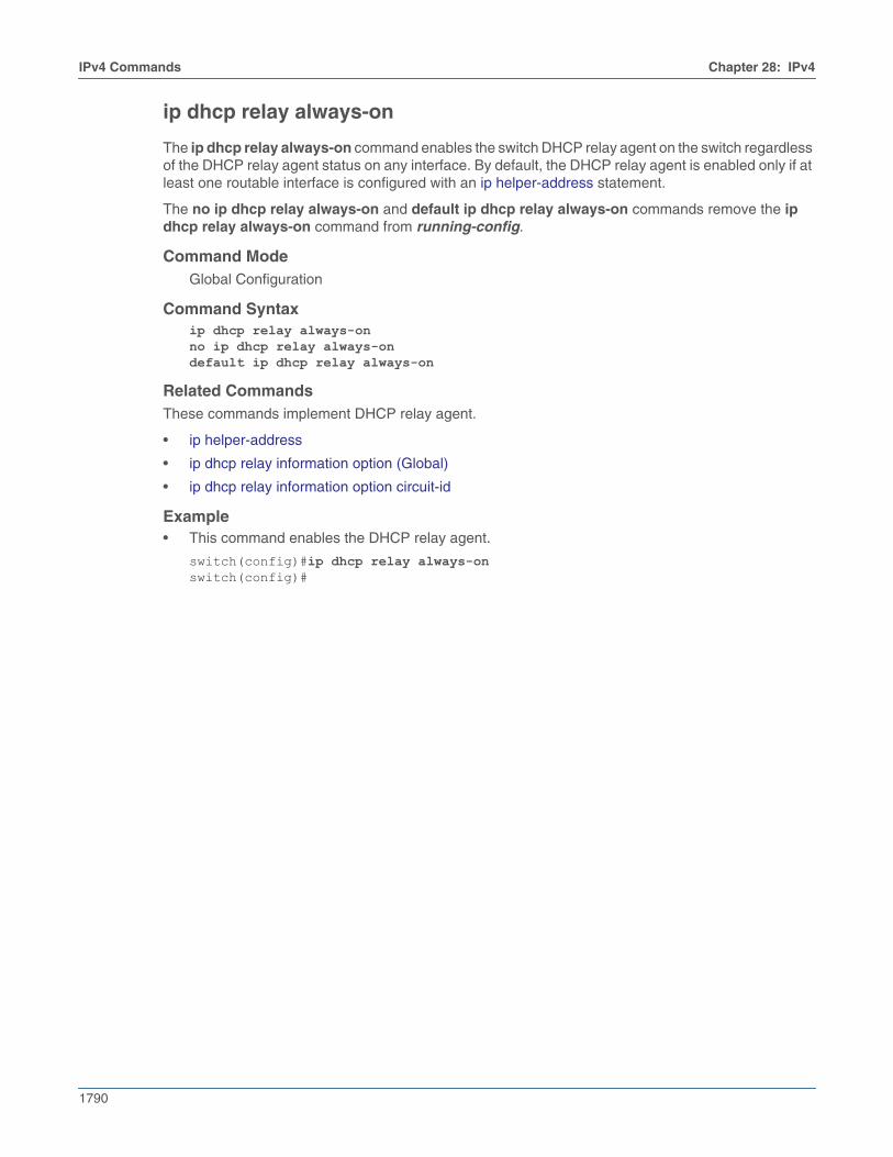
1790
IPv4 Commands Chapter 28: IPv4
ip dhcp relay always-on
The ip dhcp relay always-on command enables the switch DHCP relay agent on the switch regardlessof the DHCP relay agent status on any interface. By default, the DHCP relay agent is enabled only if atleast one routable interface is configured with an ip helper-address statement.
The no ip dhcp relay always-on and default ip dhcp relay always-on commands remove the ipdhcp relay always-on command from running-config.
Command ModeGlobal Configuration
Command Syntaxip dhcp relay always-onno ip dhcp relay always-ondefault ip dhcp relay always-on
Related CommandsThese commands implement DHCP relay agent.
• ip helper-address
• ip dhcp relay information option (Global)
• ip dhcp relay information option circuit-id
Example• This command enables the DHCP relay agent.
switch(config)#ip dhcp relay always-onswitch(config)#
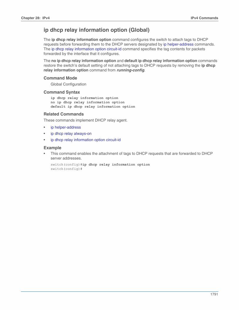
Chapter 28: IPv4 IPv4 Commands
1791
ip dhcp relay information option (Global)
The ip dhcp relay information option command configures the switch to attach tags to DHCPrequests before forwarding them to the DHCP servers designated by ip helper-address commands.The ip dhcp relay information option circuit-id command specifies the tag contents for packetsforwarded by the interface that it configures.
The no ip dhcp relay information option and default ip dhcp relay information option commandsrestore the switch’s default setting of not attaching tags to DHCP requests by removing the ip dhcprelay information option command from running-config.
Command ModeGlobal Configuration
Command Syntaxip dhcp relay information optionno ip dhcp relay information optiondefault ip dhcp relay information option
Related CommandsThese commands implement DHCP relay agent.
• ip helper-address
• ip dhcp relay always-on
• ip dhcp relay information option circuit-id
Example• This command enables the attachment of tags to DHCP requests that are forwarded to DHCP
server addresses.
switch(config)#ip dhcp relay information optionswitch(config)#
1792
IPv4 Commands Chapter 28: IPv4
ip dhcp relay information option circuit-id
The ip dhcp relay information option circuit-id command specifies the content of tags that the switchattaches to DHCP requests before they are forwarded from the configuration mode interface to DHCPserver addresses specified by ip helper-address commands. Tags are attached to outbound DHCPrequests only if the information option is enabled on the switch (ip dhcp relay information optioncircuit-id. The default value for each interface is the name and number of the interface.
The no ip dhcp relay information option circuit-id and default ip dhcp relay information optioncircuit-id commands restore the default content setting for the configuration mode interface byremoving the corresponding command from running-config.
Command ModeInterface-Ethernet ConfigurationInterface-Loopback ConfigurationInterface-Management ConfigurationInterface-Port-channel ConfigurationInterface-VLAN Configuration
Command Syntaxip dhcp relay information option circuit-id id_labelno ip dhcp relay information option circuit-id default ip dhcp relay information option circuit-id
Parameters• id_label Tag content. Format is alphanumeric characters (maximum 15 characters).
Related Commands• ip helper-address
• ip dhcp relay always-on
• ip dhcp relay information option (Global)
Example• This command configures x-1234 as the tag content for packets send from VLAN 200.
switch(config)#interface vlan 200switch(config-if-Vl200)#ip dhcp relay information option circuit-id x-1234switch(config-if-Vl200)#
Chapter 28: IPv4 IPv4 Commands
1793
ip dhcp snooping
The ip dhcp snooping command enables DHCP snooping globally on the switch. DHCP snooping isa set of layer 2 processes that can be configured on LAN switches and used with DHCP servers tocontrol network access to clients with specific IP/MAC addresses. The switch supports Option-82insertion, which is a DHCP snooping process that allows relay agents to provide remote-ID andcircuit-ID information to DHCP reply and request packets. DHCP servers use this information todetermine the originating port of DHCP requests and associate a corresponding IP address to thatport. DHCP servers use port information to track host location and IP address usage by authorizedphysical ports.
DHCP snooping uses the information option (Option-82) to include the switch MAC address (router-ID)along with the physical interface name and VLAN number (circuit-ID) in DHCP packets. After addingthe information to the packet, the DHCP relay agent forwards the packet to the DHCP server asspecified by the DHCP protocol.
DHCP snooping on a specified VLAN requires all of these conditions to be met:
• DHCP snooping is globally enabled.
• Insertion of option-82 information in DHCP packets is enabled.
• DHCP snooping is enabled on the specified VLAN.
• DHCP relay is enabled on the corresponding VLAN interface.
The no ip dhcp snooping and default ip dhcp snooping commands disables global DHCP snoopingby removing the ip dhcp snooping command from running-config.
Command ModeGlobal Configuration
Command Syntaxip dhcp snoopingno ip dhcp snoopingdefault ip dhcp snooping
Related Commands• ip dhcp snooping information option enables insertion of option-82 snooping data.
• ip helper-address enables the DHCP relay agent on a configuration mode interface.
Example• This command globally enables snooping on the switch, displaying DHCP snooping status prior
and after invoking the command.
switch(config)#show ip dhcp snoopingDHCP Snooping is disabledswitch(config)#ip dhcp snoopingswitch(config)#show ip dhcp snoopingDHCP Snooping is enabledDHCP Snooping is not operationalDHCP Snooping is configured on following VLANs: NoneDHCP Snooping is operational on following VLANs: NoneInsertion of Option-82 is disabledswitch(config)#
1794
IPv4 Commands Chapter 28: IPv4
ip dhcp snooping information option
The ip dhcp snooping information option command enables the insertion of option-82 DHCPsnooping information in DHCP packets on VLANs where DHCP snooping is enabled. DHCP snoopingis a layer 2 switch process that allows relay agents to provide remote-ID and circuit-ID information toDHCP reply and request packets. DHCP servers use this information to determine the originating portof DHCP requests and associate a corresponding IP address to that port.
DHCP snooping uses information option (Option-82) to include the switch MAC address (router-ID)along with the physical interface name and VLAN number (circuit-ID) in DHCP packets. After addingthe information to the packet, the DHCP relay agent forwards the packet to the DHCP server throughDHCP protocol processes.
DHCP snooping on a specified VLAN requires all of these conditions to be met:
• DHCP snooping is globally enabled.
• Insertion of option-82 information in DHCP packets is enabled.
• DHCP snooping is enabled on the specified VLAN.
• DHCP relay is enabled on the corresponding VLAN interface.
When global DHCP snooping is not enabled, the ip dhcp snooping information option commandpersists in running-config without any operational effect.
The no ip dhcp snooping information option and default ip dhcp snooping information optioncommands disable the insertion of option-82 DHCP snooping information in DHCP packets byremoving the ip dhcp snooping information option statement from running-config.
Command ModeGlobal Configuration
Command Syntaxip dhcp snooping information optionno ip dhcp snooping information optiondefault ip dhcp snooping information option
Related Commands• ip dhcp snooping globally enables DHCP snooping.
• ip helper-address enables the DHCP relay agent on a configuration mode interface.
Example• These commands enable DHCP snooping on DHCP packets from ports on snooping-enabled
VLANs. DHCP snooping was previously enabled on the switch.
switch(config)#ip dhcp snooping information optionswitch(config)#show ip dhcp snoopingDHCP Snooping is enabledDHCP Snooping is operationalDHCP Snooping is configured on following VLANs: 100DHCP Snooping is operational on following VLANs: 100Insertion of Option-82 is enabled Circuit-id format: Interface name:Vlan ID Remote-id: 00:1c:73:1f:b4:38 (Switch MAC)switch(config)#

Chapter 28: IPv4 IPv4 Commands
1795
ip dhcp snooping vlan
The ip dhcp snooping vlan command enables DHCP snooping on specified VLANs. DHCP snoopingis a layer 2 process that allows relay agents to provide remote-ID and circuit-ID information in DHCPpackets. DHCP servers use this data to determine the originating port of DHCP requests and associatea corresponding IP address to that port. DHCP snooping is configured on a global and VLAN basis.
VLAN snooping on a specified VLAN requires each of these conditions:
• DHCP snooping is globally enabled.
• Insertion of option-82 information in DHCP packets is enabled.
• DHCP snooping is enabled on the specified VLAN.
• DHCP relay is enabled on the corresponding VLAN interface.
When global DHCP snooping is not enabled, the ip dhcp snooping vlan command persists inrunning-config without any operational affect.
The no ip dhcp snooping information option and default ip dhcp snooping information optioncommands disable DHCP snooping operability by removing the ip dhcp snooping informationoption statement from running-config.
Command ModeGlobal Configuration
Command Syntaxip dhcp snooping vlan v_rangeno ip dhcp snooping vlan v_rangedefault ip dhcp snooping vlan v_range
Parameters• v_range VLANs upon which snooping is enabled. Formats include a number, a number range,
or a comma-delimited list of numbers and ranges. Numbers range from 1 to 4094.
Related Commands• ip dhcp snooping globally enables DHCP snooping.
• ip dhcp snooping information option enables insertion of option-82 snooping data.
• ip helper-address enables the DHCP relay agent on a configuration mode interface.

1796
IPv4 Commands Chapter 28: IPv4
Example• These commands enable DHCP snooping globally, DHCP on VLAN interface100, and DHCP
snooping on VLAN 100.
switch(config)#ip dhcp snoopingswitch(config)#ip dhcp snooping information optionswitch(config)#ip dhcp snooping vlan 100switch(config)#interface vlan 100switch(config-if-Vl100)#ip helper-address 10.4.4.4switch(config-if-Vl100)#show ip dhcp snoopingDHCP Snooping is enabledDHCP Snooping is operationalDHCP Snooping is configured on following VLANs: 100DHCP Snooping is operational on following VLANs: 100Insertion of Option-82 is enabled Circuit-id format: Interface name:Vlan ID Remote-id: 00:1c:73:1f:b4:38 (Switch MAC)switch(config)#
Chapter 28: IPv4 IPv4 Commands
1797
ip hardware fib ecmp resilience
The ip hardware fib ecmp resilience command enables resilient ECMP for the specified IP addressprefix and configures a fixed number of next hop entries in the hardware ECMP table for that prefix. Inaddition to specifying the maximum number of next hop addresses that the table can contain for theprefix, the command includes a redundancy factor that allows duplication of each next hop address.The fixed table space for the address is the maximum number of next hops multiplied by theredundancy factor.
Resilient ECMP is useful when it is not desirable for routes to be rehashed due to link flap, as whenECMP is being used for load balancing.
The no ip hardware fib ecmp resilience and default ip hardware fib ecmp resilience commandsrestore the default hardware ECMP table management by removing the ip hardware fib ecmpresilience command from running-config.
Command ModeGlobal Configuration
Command Syntaxip hardware fib ecmp resilience net_addr capacity nhop_max redundancy duplicatesno ip hardware fib ecmp resilience net_addrdefault ip hardware fib ecmp resilience net_addr
Parameters• net_addr IP address prefix managed by command. (CIDR or address-mask).
• nhop_max Maximum number of nexthop addresses for specified IP address prefix. Value rangevaries by platform:
• Helix: <2 to 64>
• Trident: <2 to 32>
• Trident II: <2 to 64>
• duplicates Specifies the redundancy factor. Value ranges from 1 to 128.
Example• This command configures a hardware ECMP table space of 24 entries for the IP address
10.14.2.2/24. A maximum of six next-hop addresses can be specified for the IP address. When thetable contains six next-hop addresses, each appears in the table four times. When the tablecontains fewer than six next-hop addresses, each is duplicated until the 24 table entries are filled.
switch(config)#ip hardware fib ecmp resilience 10.14.2.2/24 capacity 6 redundancy 4switch(config)#
1798
IPv4 Commands Chapter 28: IPv4
ip hardware fib optimize
The ip hardware fib optimize command enables IPv4 route scale. The platform layer 3 agent isrestarted to ensure IPv4 routes are optimized with the agent SandL3Unicast terminate command forthe configuration mode interface.
Command ModeGlobal Configuration
Command Syntaxip hardware fib optimize exact-match prefix-length <prefix-length> <optional: prefix-length>no ip hardware fib optimize exact-match prefix-length <prefix-length> <optional: prefix-length>
Parameters• prefix-length The length of the prefix equal to 12, 16, 20, 24, 28, or 32. One additional
prefix-length limited to the prefix-length of 32 is optional.
Related Commands• agent SandL3Unicast terminate enables restarting the layer 3 agent to ensure IPv4 routes are
optimized.
• show platform arad ip route shows resources for all IPv4 routes in hardware. Routes that use theadditional hardware resources will appear with an asterisk.
• show platform arad ip route summary shows hardware resource usage of IPv4 routes.
Examples• This configuration command allows configuring prefix lengths 12 and 32.
switch(config)#ip hardware fib optimize exact-match prefix-length 12 32! Please restart layer 3 forwarding agent to ensure IPv4 routes are optimized
One of the two prefixes in this command is a prefix-length of 32, which is required in the instancewhere there are two prefixes. For this command to take effect, the platform layer 3 agent must berestarted.
This configuration command restarts the platform layer 3 agent to ensure IPv4 routes areoptimized.
switch(config)#agent SandL3Unicast terminateSandL3Unicast was terminated
Restarting the platform layer 3 agent results in deletion of all IPv4 routes, which are re-added tothe hardware.
• This configuration command allows configuring prefix lengths 32 and 16.
switch(config)#ip hardware fib optimize exact-match prefix-length 32 16! Please restart layer 3 forwarding agent to ensure IPv4 routes are optimized
One of the two prefixes in this command is a prefix-length of 32, which is required in the instancewhere there are two prefixes. For this command to take effect, the platform layer 3 agent must berestarted.
This configuration command restarts the platform layer 3 agent to ensure IPv4 routes areoptimized.
switch(config)#agent SandL3Unicast terminateSandL3Unicast was terminated
Chapter 28: IPv4 IPv4 Commands
1799
Restarting the platform layer 3 agent results in deletion of all IPv4 routes, which are re-added tothe hardware.
• This configuration command allows configuring prefix length 24.
switch(config)#ip hardware fib optimize exact-match prefix-length 24! Please restart layer 3 forwarding agent to ensure IPv4 routes are optimized
In this instance, there is only one prefix-length, so a prefix-length of 32 is not required. For thiscommand to take effect, the platform layer 3 agent must be restarted.
This configuration command restarts the platform layer 3 agent to ensure IPv4 routes areoptimized.
switch(config)#agent SandL3Unicast terminateSandL3Unicast was terminated
Restarting the platform layer 3 agent results in deletion of all IPv4 routes, which are re-added tothe hardware.
• This configuration command allows configuring prefix length 32.
switch(config)#ip hardware fib optimize exact-match prefix-length 32! Please restart layer 3 forwarding agent to ensure IPv4 routes are optimized
For this command to take effect, the platform layer 3 agent must be restarted.
This configuration command restarts the platform layer 3 agent to ensure IPv4 routes areoptimized.
switch(config)#agent SandL3Unicast terminateSandL3Unicast was terminated
Restarting the platform layer 3 agent results in deletion of all IPv4 routes, which are re-added tothe hardware.
Example
• This configuration command disables configuring prefix lengths 12 and 32.
switch(config)#no ip hardware fib optimize exact-match prefix-length 12 32! Please restart layer 3 forwarding agent to ensure IPv4 routes are not optimized
One of the two prefixes in this command is a prefix-length of 32, which is required in the instancewhere there are two prefixes. For this command to take effect, the platform layer 3 agent must berestarted.

1800
IPv4 Commands Chapter 28: IPv4
ip helper-address
The ip helper-address command enables the DHCP relay agent on the configuration mode interfaceand specifies a forwarding address for DHCP requests. An interface that is configured with multiplehelper-addresses forwards DHCP requests to all specified addresses.
The no ip helper-address and default ip helper-address commands remove the corresponding iphelper-address command from running-config. Commands that do not specify an IP helper-addressremove all helper-addresses from the interface.
Command ModeInterface-Ethernet ConfigurationInterface-Port-channel ConfigurationInterface-VLAN Configuration
Command Syntaxip helper-address ipv4_addr [vrf vrf_name] [source-address ipv4_addr | source-interface INTERFACES]no ip helper-address [ipv4_addr]default ip helper-address [ipv4_addr]
Parameters• vrf vrf_name specify the user-defined VRF for DHCP server.
• ipv4_addr specify the DHCP server address accessed by interface.
• source-address ipv4_addr specify the source IPv4 address to communicate with DHCP server.
• source-interface INTERFACES specify the source interface to communicate with DHCPserver. Options include:
• Ethernet eth_num specify the Ethernet interface number.
• Loopback lpbck_num specify the loopback interface number. Value ranges from 0 to 1000.
• Management mgmt_num specify the management interface number. Accepted values are1 and 2.
• Port-Channel {int_num | sub_int_num} specify the port-channel interface or subinterfacenumber. Value of interface ranges from 1 to 2000. Value of sub-interface ranges from 1 to 4094.
• Tunnel tnl_num specify the tunnel interface number. Value ranges from 0 to 255.
• VLAN vlan_num specify the Ethernet interface number. Value ranges from 1 to 4094.
Related Commands• ip dhcp relay always-on
• ip dhcp relay information option (Global)
• ip dhcp relay information option circuit-id
GuidelinesIf the source-address parameter is specified, then the DHCP client receives an IPv4 address from thesubnet of source IP address. The source-address must be one of the configured addresses on theinterface.
Chapter 28: IPv4 IPv4 Commands
1801
Examples• This command enables DHCP relay on the VLAN interface 200; and configure the switch to forward
DHCP requests received on this interface to the server at 10.10.41.15.
switch(config)#interface vlan 200switch(config-if-Vl200)#ip helper-address 10.10.41.15switch(config-if-Vl200)#show activeinterface Vlan200 ip helper-address 10.10.41.15switch(config-if-Vl200)#
• This command enables DHCP relay on the interface Ethernet 1/2; and configures the switch to use2.2.2.2 as the source IP address when relaying IPv4 DHCP messages to the server at 1.1.1.1.
switch(config)#interface ethernet 1/2switch(config-if-Et1/2)#ip helper-address 1.1.1.1 source-address 2.2.2.2switch(config-if-Et1/2)#
1802
IPv4 Commands Chapter 28: IPv4
ip icmp redirect
The ip icmp redirect command enables the transmission of ICMP redirect messages. Routers sendICMP redirect messages to notify data link hosts of the availability of a better route for a specificdestination.
The no ip icmp redirect disables the switch from sending ICMP redirect messages.
Command ModeGlobal Configuration
Command Syntaxip icmp redirectno ip icmp redirectdefault ip icmp redirect
Example• This command disables the redirect messages.
switch(config)#no ip icmp redirectswitch(config)#show running-config
<-------OUTPUT OMITTED FROM EXAMPLE-------->!no ip icmp redirectip routing!
<-------OUTPUT OMITTED FROM EXAMPLE--------> switch(config)#
Chapter 28: IPv4 IPv4 Commands
1803
ip load-sharing
The ip load-sharing command provides the hash seed to an algorithm that the switch uses todistribute data streams among multiple equal-cost routes to an individual IPv4 subnet.
In a network topology using Equal-Cost Multipath routing, all switches performing identical hashcalculations may result in hash polarization, leading to uneven load distribution among the data paths.Hash polarization is avoided when switches use different hash seeds to perform different hashcalculations.
The no ip load-sharing and default ip load-sharing commands return the hash seed to the defaultvalue of zero by removing the ip load-sharing command from running-config.
Command ModeGlobal Configuration
Command Syntaxip load-sharing HARDWARE seedno ip load-sharing HARDWAREdefault ip load-sharing HARDWARE
Parameters• HARDWARE The ASIC switching device. The available option depend on the switch platform.
Verify available options with the CLI ? command.
• arad
• fm6000
• petraA
• trident
• seed The hash seed. Value range varies by switch platform. The default value on all platformsis 0.
• when HARDWARE=arad seed ranges from 0 to 2.
• when HARDWARE=fm6000 seed ranges from 0 to 39.
• when HARDWARE=petraA seed ranges from 0 to 2.
• when HARDWARE=trident seed ranges from 0 to 5.
Example• This command sets the IPv4 load sharing hash seed to one on FM6000 platform switches.
switch(config)#ip load-sharing fm6000 1switch(config)#

1804
IPv4 Commands Chapter 28: IPv4
ip local-proxy-arp
The ip local-proxy-arp command enables local proxy ARP (Address Resolution Protocol) on theconfiguration mode interface. When local proxy ARP is enabled, ARP requests received on theconfiguration mode interface will return an IP address even when the request comes from within thesame subnet.
The no ip local-proxy-arp and default ip local-proxy-arp commands disable local proxy ARP on theconfiguration mode interface by removing the corresponding ip local-proxy-arp command fromrunning-config.
Command ModeInterface-Ethernet ConfigurationInterface-Loopback ConfigurationInterface-Management ConfigurationInterface-Port-channel ConfigurationInterface-VLAN Configuration
Command Syntaxip local-proxy-arpno ip local-proxy-arpdefault ip local-proxy-arp
Example• These commands enable local proxy ARP on VLAN interface 140.
switch(config)#interface vlan 140switch(config-if-Vl140)#ip local-proxy-arpswitch(config-if-Vl140)#show activeinterface Vlan140 ip local-proxy-arpswitch(config-if-Vl140)#
Chapter 28: IPv4 IPv4 Commands
1805
ip multicast count
The ip multicast count command enables the IPv4 multicast route traffic counter of group and sourceaddresses in either bytes or packets.
The no ip multicast count command deletes all multicast counters including the routes of group andsource addresses.
The no ip multicast count group_address source_address command removes the currentconfiguration of the specified group and source addresses. It does not delete the counter because thewildcard is still active.
The default ip multicast count command reverts the current counter configuration of multicast routeto the default state.
Command ModeGlobal Configuration
Command Syntaxip multicast count [group_address [source_address] | bytes | packets]no ip multicast count [group_address [source_address] | bytes | packets]default ip multicast count [group_address [source_address] | bytes | packets]
Parameters• group_address configures the multicast route traffic count of the specified group address
• source_address configures the multicast route traffic count of the specified group andsource addresses
• bytes configures the multicast route traffic count to bytes
• packets configures the multicast route traffic count to packets
GuidelinesThis command is supported on the FM6000 platform only.
Examples• This command configures the multicast route traffic count to bytes.
switch(config)#ip multicast count bytes
• This command configures the multicast route traffic count of the specified group and sourceaddresses.
switch(config)#ip multicast count 10.50.30.23 45.67.89.100
• This command deletes all multicast counters including the routes of group and source addresses.
switch(config)#no ip multicast count
• This command reverts the current multicast route configuration to the default state.
switch(config)#default ip multicast count
1806
IPv4 Commands Chapter 28: IPv4
ip nat destination static
The ip nat destination static command enables NAT of a specified destination address for theconfiguration mode interface. This command installs hardware translation entries for forward andreverse unicast traffic. When the rule specifies a multicast group, the command does not install thereverse path in hardware. The command may include an access control list to filter packets fortranslation.
When configuring twice NAT, an arbitrary NAT group number is used to associate the source NAT anddestination NAT rules. This number must be the same in both rules.
The no ip nat destination static and default ip nat destination static commands disables NATtranslation of the specified destination address by removing the corresponding ip nat destinationstatic command from running_config.
Command ModeInterface-Ethernet ConfigurationInterface-Port-channel ConfigurationInterface-VLAN Configuration
Command Syntaxip nat destination static ORIGINAL [FILTER] TRANSLATED [PROT_TYPE] [group group_number]no ip nat destination static ORIGINAL [FILTER] TRANSLATED [PROT_TYPE] [group group_number]default ip nat destination static ORIGINAL [FILTER] TRANSLATED [PROT_TYPE] [group group_number]
Parameters• ORIGINAL Destination address to be modified. Options include:
• local_ipv4 IPv4 address.
• local_ipv4 local_port IPv4 address and port (port value ranges from 1 to 65535).
• FILTER Access control list that filters packets. Options include:
• <no parameter> All packets with specified destination address are cleared.
• access-list list_name List that specifies the packets that are cleared. Not supported whenconfiguring twice NAT.
• TRANSLATED Destination address of translated packet. Options include:
• global_ipv4 IPv4 address.
• global_ipv4 global_port IPv4 address and port (port value ranges from 1 to 65535). Whenconfiguring twice NAT, source and destination NAT rules must either both specify a porttranslation or both not specify a port translation.
• PROT_TYPE Filters packets based on protocol type. Options include:
• <no parameter> All packets with specified destination address are cleared.
• protocol tcp TCP packets with specified destination address are cleared.
• protocol udp UDP packets with specified destination address are cleared.
• group group_number Used only when configuring twice NAT, the NAT group number associatesa source NAT rule with a destination NAT rule on the same interface. The group number (valuesrange from 1 to 255) is arbitrary, but must be the same in both rules.

Chapter 28: IPv4 IPv4 Commands
1807
Example• These commands configure VLAN 201 to translate destination address 10.24.1.10 to
168.32.14.15.
switch(config)#interface vlan 201switch(config-if-Vl201)#ip nat destination static 10.24.1.10 168.32.14.15switch(config-if-Vl201)#
• These commands configure VLAN 201 to translate the source address 10.24.1.10 to 168.32.14.15for all packets with IP destination addresses in the 168.10.1.1/32 subnet.
switch(config)#ip access-list ACL2switch(config-acl-ACL2)#permit ip 168.10.1.1/32 anyswitch(config-acl-ACL2)#exitswitch(config)#interface vlan 201switch(config-if-Vl201)#ip nat destination static 10.24.1.10 access-list ACL2 168.32.14.15switch(config-if-Vl201)#
• These commands configure Ethernet interface 2 to translate the local source address 10.24.1.10to the global source address 168.32.14.15, and to translate the local destination address10.68.104.3 to the global destination address 168.25.10.7 for all packets moving through theinterface. The use of NAT group 3 is arbitrary, but must be the same in both rules.
switch(config)#interface ethernet 2switch(config-if-Et2)#ip nat source static 10.24.1.10 168.32.14.15 group 3switch(config-if-Et2)#ip nat destination static 10.68.104.3 168.25.10.7 group 3
1808
IPv4 Commands Chapter 28: IPv4
ip nat pool
The ip nat pool command identifies a pool of addresses using start address, end address, and eithernetmask or prefix length. If its starting IP address and ending IP address are the same, there is onlyone address in the address pool.
The no ip nat pool removes the ip nat pool command from running_config.
Command ModeGlobal Configuration
Command Syntaxip nat pool pool_name [ADDRESS_SPAN] SUBNET_SIZEno ip nat pool pool_namedefault ip nat pool pool_name
Parameters• pool_name name of the IP address pool.
• ADDRESS_SPAN Options include:
• start_addr The first IP address in the address pool (IPv4 addresses in dotted decimalnotation).
• end_addr The last IP address in the address pool. (IPv4 addresses in dotted decimalnotation).
• SUBNET_SIZE this functions as a sanity check to ensure it is not a network or broadcastnetwork. Options include:
• netmask ipv4_addr The netmask of the address pool’s network (dotted decimal notation).
• prefix-length <0 to 32> The number of bits of the netmask (of the address pool’s network)that are ones (how many bits of the address indicate network).
Examples• This command configures the pool of addresses using start address, end address, and prefix
length of 24.
switch(config)#ip nat pool poo1 10.15.15.15 10.15.15.25 prefix-length 24switch(config)
• This command removes the pool of addresses.
switch(config)# no ip nat pool poo1 10.15.15.15 10.15.15.25 prefix-length 24switch(config)
Chapter 28: IPv4 IPv4 Commands
1809
ip nat source dynamic
The ip nat source dynamic command enables NAT of a specified source address for packets sent andreceived on the configuration mode interface. This command installs hardware translation entries forforward and reverse traffic. When the rule specifies a multicast group, the command does not installthe reverse path in hardware. The command may include an access control list to filter packets fortranslation.
The no ip nat source dynamic and default ip nat source dynamic commands disables NATtranslation of the specified destination address by removing the corresponding ip nat source dynamiccommand from running_config.
Note Ethernet and Port-channel interfaces should be configured as routed ports.
Command ModeInterface-Ethernet ConfigurationInterface-Port-channel ConfigurationInterface-VLAN Configuration
Command Syntaxip nat source dynamic access-list acl_name POOL_TYPEno ip nat source dynamic access-list acl_namedefault ip nat source dynamic access-list acl_name
Parameters• acl_name Access control list that controls the internal network addresses eligible for NAT.
• POOL_TYPE Options include:
• overload Translates multiple local addresses to a single global address. When overloadingis enabled, conversations using the same IP address are distinguished by their TCP or UDPport number.
• pool pool_name The name of the IP address pool. The pool is defined using the ip nat poolcommand.
The pool option is required even if the pool has just one address. NAT uses that one addressfor all of the translations.
• pool_fullcone Enables full cone NAT where all requests from the same internal IPaddress and port are mapped to the same external IP address and port.
Example• This command configures the dynamic NAT source address and sets the NAT overload for pool P2.
switch(config)#interface ethernet 3/1switch(config-if-Et3/1)#ip nat source dynamic access-list ACL2 pool p2 switch#
• This command disables the NAT source translation on interface Ethernet 3/1.
switch(config)#interface ethernet 3/1switch(config-if-Et3/1)# no ip nat source dynamic access-list ACL2 switch(config-if-Et3/1)#

1810
IPv4 Commands Chapter 28: IPv4
ip nat source static
The ip nat source static command enables NAT of a specified source address for the configurationmode interface. This command installs hardware translation entries for forward and reverse unicasttraffic. When the rule specifies a multicast group, the command does not install the reverse path inhardware. The command may include an access control list to filter packets for translation.
When configuring twice NAT, an arbitrary NAT group number is used to associate the source NAT anddestination NAT rules. This number must be the same in both rules.
The no ip nat source static and default ip nat source static commands disables NAT translation ofthe specified source address by removing the corresponding ip nat source command fromrunning_config.
Command ModeInterface-Ethernet ConfigurationInterface-Port-channel ConfigurationInterface-VLAN Configuration
Command Syntaxip nat source static ORIGINAL [FILTER] TRANSLATED [PROT_TYPE] [group group_number]no ip nat source static ORIGINAL [FILTER] TRANSLATED [PROT_TYPE] [group group_number]default ip nat source static ORIGINAL [FILTER] TRANSLATED [PROT_TYPE] [group group_number]
Parameters• ORIGINAL Source address to be modified. Options include:
• original_ipv4 IPv4 address.
• original_ipv4 original_port IPv4 address and port (port value ranges from 1 to 65535).
• FILTER Access control list that filters packets. Options include:
• <no parameter> All packets with specified source address are cleared.
• access-list list_name List that specifies the packets that are cleared. Not supported whenconfiguring twice NAT.
• TRANSLATED Source address of translated packet. Options include:
• translated_ipv4 IPv4 address.
• translated_ipv4 translated_port IPv4 address and port (port value ranges from 1 to 65535).When configuring twice NAT, source and destination NAT rules must either both specify a porttranslation or both not specify a port translation.
• PROT_TYPE Filters packets based on protocol type. Options include:
• <no parameter> All packets with specified source address are cleared.
• protocol tcp TCP packets with specified source address are cleared.
• protocol udp UDP packets with specified source address are cleared.
• group group_number Used only when configuring twice NAT, the NAT group number associatesa source NAT rule with a destination NAT rule on the same interface. The group number (valuesrange from 1 to 255) is arbitrary, but must be the same in both rules.
Restrictions• If ORIGINAL includes a port, TRANSLATED must also include a port.
• If ORIGINAL does not include a port, TRANSLATED cannot include a port.
Chapter 28: IPv4 IPv4 Commands
1811
Example• These commands configure VLAN 101 to translate source address 10.24.1.10 to 168.32.14.15.
switch(config)#interface vlan 101switch(config-if-Vl101)#ip nat source static 10.24.1.10 168.32.14.15switch(config-if-Vl101)#
• These commands configure VLAN 100 to translate the source address 10.24.1.10 to 168.32.14.15for all packets with IP destination addresses in the 168.10.1.1/32 subnet.
switch(config)#ip access-list ACL1switch(config-acl-ACL1)#permit ip any 168.10.1.1/32switch(config-acl-ACL1)#exitswitch(config)#interface vlan 101switch(config-if-Vl101)#ip nat source static 10.24.1.10 access-list ACL1 168.32.141.15switch(config-if-Vl101)#
• These commands configure Ethernet interface 2 to translate the local source address 10.24.1.10to the global source address 168.32.14.15, and to translate the local destination address10.68.104.3 to the global destination address 168.25.10.7 for all packets moving through theinterface. The use of NAT group 3 is arbitrary, but must be the same in both rules.
switch(config)#interface ethernet 2switch(config-if-Et2)#ip nat source static 10.24.1.10 168.32.14.15 group 3switch(config-if-Et2)#ip nat destination static 10.68.104.3 168.25.10.7 group 3
1812
IPv4 Commands Chapter 28: IPv4
ip nat translation counters
The ip nat translation counters command enables the feature to count packets that are translated bystatic and twice NAT rules in hardware. Once this feature is enabled, all current rules in hardware andnew rules that are configured after running this command receive policers for counting packets.
The no ip nat translation counters and default ip nat translation counters commands disable thepacket counter feature for static and twice NAT connections.
Command ModeGlobal Configuration
Command Syntaxip nat translation countersno ip nat translation countersdefault ip nat translation counters
GuidelinesThe ip nat translation counters command is supported on the DCS-7150 series switches only. Thiscommand is solely intended to debug static and twice NAT translation failures in hardware. Disable thisfeature after completing troubleshooting. If this feature remains enabled even when the count of staticconnections exceed 275, it can cause unpredictable behavior including restart of FocalPointV2 agent.The restart of FocalPointV2 agent results in traffic disruption.
Example• The ip nat translation counters command enables the packet counter feature for static and twice
NAT connections. Using the show ip nat translation hardware detail and show ip nattranslation twice hardware detail commands, you can verify the packet count.
switch(config)#ip nat translation countersswitch(config)#show ip nat translation hardware detailSource IP Destination IP Translated IP TGT Type Intf Proto Packets Packets Reply------------------------------------------------------------------------------------------------------------192.168.10.2:0 - 20.1.10.2:0 SRC STAT Vl2640 - 2 1192.168.110.2:0 - 20.1.110.2:0 SRC STAT Vl2640 - 2 1switch(config)#show ip nat translation twice hardware detailSource IP Destination IP Translated Translated Intf Group Packets Packets Src IP Dst IP Proto Reply---------------------------------------------------------------------------------------------------------192.16.50.2:0 10.1.50.2:0 20.1.50.2:0 10.1.60.2:0 Vl2922 2 - 2 119.16.150.2:0 10.1.150.2:0 20.1.150.2:0 10.1.160.2:0 Vl2922 12 - 2
Chapter 28: IPv4 IPv4 Commands
1813
ip nat translation low-mark
The ip nat translation low-mark command configures the minimum threshold that triggers theresumption of programming new NAT translation connections.
The ip nat translation max-entries command specifies the maximum number of NAT translationconnections that can be stored. When this limit is reached, new connections are dropped instead ofbeing programmed in hardware or software. At this point no new connections will be programmed untilthe number of stored entries drop below the configured low-mark, expressed as a percentage of themax-entries value. The default low mark value is 90%.
The no ip nat translation low-mark and default ip nat translation low-mark commands restores thedefault low-mark value by removing the ip nat translation low-mark command from running_config.
Command ModeGlobal Configuration
Command Syntaxip nat translation low-mark thresholdno ip nat translation low-markdefault ip nat translation low-mark
Parameters• threshold Percentage of maximum connection entries. Value ranges from 1 to 99. Default is 90.
Examples• This command globally sets the translation low mark of 93%.
switch(config)#ip nat translation low-mark 93switch(config)#
1814
IPv4 Commands Chapter 28: IPv4
ip nat translation max-entries
The ip nat translation max-entries command specifies maximum number of NAT translationconnections. After this threshold is reached, new connections are dropped until the number ofprogrammed connections is reduced below the level specified by the ip nat translation low-markcommand.
The no ip nat translation max-entries and default ip nat translation max-entries commandsremoves the maximum connection limit and resets the parameter value to zero by removing the ip nattranslation max-entries command from running_config.
Command ModeGlobal Configuration
Command Syntaxip nat translation max-entries connectionsno ip nat translation max-entriesdefault ip nat translation max-entries
Parameters• connections The maximum number of NAT translation connections. Value ranges from 0 to
4294967295. Default value is 0, which removes the connection limit.
Examples• This command limits the number of NAT translation connections the switch can store to 3000.
switch(config)#ip nat translation max-entries 3000switch(config)#
Chapter 28: IPv4 IPv4 Commands
1815
ip nat translation tcp-timeout
The ip nat translation tcp-timeout command specifies the translation timeout period for translationtable entries. The timeout period specifies the interval during which the switch will attempt to reuse anexisting TCP translation for devices specified by table entries.
The no ip nat translation tcp-timeout and default ip nat translation tcp-timeout commands resetthe timeout to its default by removing the corresponding ip nat translation tcp-timeout command fromrunning_config.
Command ModeGlobal Configuration
Command Syntaxip nat translation tcp-timeout periodno ip nat translation tcp-timeoutdefault ip nat translation tcp-timeout
Parameters• period Time-out period in seconds for port translations. Value ranges from 0 to 4294967295.
Default value is 86400 (24 hours).
Examples• This command sets the TCP timeout for translations to 600 seconds.
switch(config)# ip nat translation tcp-timeout 600switch(config)#
• This command removes the TCP translation timeout.
switch(config)# no ip nat translation tcp-timeout switch(config)#
1816
IPv4 Commands Chapter 28: IPv4
ip nat translation udp-timeout
The ip nat translation udp-timeout command specifies the translation timeout period for translationtable entries. The timeout period specifies the interval the switch attempts to establish a UDPconnection with devices specified by table entries.
The no ip nat translation udp-timeout and default ip nat translation udp-timeout commandsdisables NAT translation of the specified destination address by removing the corresponding ip nattranslation udp-timeout command from running_config.
Command ModeGlobal Configuration
Command Syntaxip nat translation udp-timeout periodno ip nat translation udp-timeoutdefault ip nat translation udp-timeout
Parameters• period Value ranges from 0 to 4294967295. Default value is 300 (5 minutes).
Examples• This command globally sets the timeout for UDP to 800 seconds.
switch(config)# ip nat translation udp-timeout 800
• This command removes the timeout for UDP.
switch(config)# no ip nat translation udp-timeout
Chapter 28: IPv4 IPv4 Commands
1817
ip proxy-arp
The ip proxy-arp command enables proxy ARP on the configuration mode interface. Proxy ARP isdisabled by default.
The no ip proxy-arp and default ip proxy-arp commands disable proxy ARP on the configurationmode interface by removing the corresponding ip proxy-arp command from running-config.
Command ModeInterface-Ethernet ConfigurationInterface-Loopback ConfigurationInterface-Management ConfigurationInterface-Port-channel ConfigurationInterface-VLAN Configuration
Command Syntaxip proxy-arpno ip proxy-arpdefault ip proxy-arp
Examples• This command enables proxy ARP on Ethernet interface 4.
switch(config)#interface ethernet 4switch(config-if-Et4)#ip proxy-arpswitch(config-if-Et4)#

1818
IPv4 Commands Chapter 28: IPv4
ip route
The ip route command creates a static route. The destination is a network segment; the nexthopaddress is either an IPv4 address or a routable port. When multiple routes exist to a destination prefix,the route with the lowest administrative distance takes precedence.
By default, the administrative distance assigned to static routes is 1. Assigning a higher administrativedistance to a static route configures it to be overridden by dynamic routing data. For example, a staticroute with an administrative distance value of 200 is overridden by OSPF intra-area routes, which havea default administrative distance of 110.
Tags are used by route maps to filter routes. The default tag value on static routes is 0.
Multiple routes with the same destination and the same administrative distance comprise an EqualCost Multi-Path (ECMP) route. The switch attempts to spread outbound traffic equally through allECMP route paths. All paths comprising an ECMP are assigned identical tag values; commands thatchange the tag value of a path change the tag value of all paths in the ECMP.
The no ip route and default ip route commands delete the specified static route by removing thecorresponding ip route command from running-config. Commands that do not list a nexthop addressremove all ip route statements with the specified destination from running-config. If an ip routestatement exists for the same IP address in multiple VRFs, each must be removed separately. All staticroutes in a user-defined VRF are deleted when the VRF is deleted.
Command ModeGlobal Configuration
Command Syntaxip route [VRF_INSTANCE] dest_net NEXTHOP [DISTANCE] [TAG_OPTION] [RT_NAME]no ip route [VRF_INSTANCE] dest_net [NEXTHOP] [DISTANCE]default ip route [VRF_INSTANCE] dest_net [NEXTHOP] [DISTANCE]
Parameters• VRF_INSTANCE Specifies the VRF instance being modified.
• <no parameter> Changes are made to the default VRF.
• vrf vrf_name Changes are made to the specified VRF.
• dest_net Destination IPv4 subnet (CIDR or address-mask notation).
• NEXTHOP Location or access method of next hop device. Options include:
• ipv4_addr An IPv4 address.
• null0 Null0 interface.
• ethernet e_num Ethernet interface specified by e_num.
• loopback l_num Loopback interface specified by l_num.
• management m_num Management interface specified by m_num.
• port-channel p_num Port-channel interface specified by p_num.
• vlan v_num VLAN interface specified by v_num.
• vxlan vx_num VXLAN interface specified by vx_num.
• DISTANCE Administrative distance assigned to route. Options include:
• <no parameter> Route assigned default administrative distance of one.
• <1-255> The administrative distance assigned to route.
• TAG_OPTION static route tag. Options include:
Chapter 28: IPv4 IPv4 Commands
1819
• <no parameter> Assigns default static route tag of 0.
• tag t_value Static route tag value. t_value ranges from 0 to 4294967295.
• RT_NAME Associates descriptive text to the route. Options include:
• <no parameter> No text is associated with the route.
• name descriptive_text The specified text is assigned to the route.
Related Commands• ip route nexthop-group command creates a static route that specifies a Nexthop Group to
determine the Nexthop address.
Example• This command creates a static route in the default VRF.
switch(config)#ip route 172.17.252.0/24 vlan 2000switch(config)#
1820
IPv4 Commands Chapter 28: IPv4
ip routing
The ip routing command enables IPv4 routing. When IPv4 routing is enabled, the switch attempts todeliver inbound packets to destination IPv4 addresses by forwarding them to interfaces or next hopaddresses specified by the forwarding table.
The no ip routing and default ip routing commands disable IPv4 routing by removing the ip routingcommand from running-config. When IPv4 routing is disabled, the switch attempts to deliver inboundpackets to their destination MAC addresses. When this address matches the switch’s MAC address,the packet is delivered to the CPU. IP packets with IPv4 destinations that differ from the switch’saddress are typically discarded. The delete-static-routes option removes static entries from therouting table.
IPv4 routing is disabled by default.
Command ModeGlobal Configuration
Command Syntaxip routing [VRF_INSTANCE]no ip routing [DELETE_ROUTES] [VRF_INSTANCE]default ip routing [DELETE_ROUTES] [VRF_INSTANCE]
Parameters• DELETE_ROUTES Resolves routing table static entries when routing is disabled.
• <no parameter> Routing table retains static entries.
• delete-static-routes Static entries are removed from the routing table.
• VRF_INSTANCE specifies the VRF instance being modified.
• <no parameter> changes are made to the default VRF.
• vrf vrf_name changes are made to the specified user-defined VRF.
Example• This command enables IPv4 routing.
switch(config)#ip routingswitch(config)#

Chapter 28: IPv4 IPv4 Commands
1821
ip source binding
IP source guard (IPSG) is supported on Layer 2 Port-Channels, not member ports. The IPSGconfiguration on port channels supersedes the configuration on the physical member ports. Hence,source IP MAC binding entries should be configured on port channels. When configured on a portchannel member port, IPSG does not take effect until this port is deleted from the port channelconfiguration.
Note IP source bindings are also used by static ARP inspection.
The no ip source binding and default ip source binding commands exclude parameters from IPSGfiltering, and set the default for ip source binding.
Command ModeInterface-Ethernet Configuration
Command Syntaxip source binding [IP_ADDRESS] [MAC_ADDRESS] vlan [VLAN_RANGE] interface [INTERFACE]no ip source binding [IP_ADDRESS] [MAC_ADDRESS] vlan [VLAN_RANGE] interface [INTERFACE]default ip source binding [IP_ADDRESS] [MAC_ADDRESS] vlan [VLAN_RANGE] interface [INTERFACE]
Parameters• IP_ADDRESS Specifies the IP ADDRESS.
• MAC_ADDRESS Specifies the MAC ADDRESS.
• VLAN_RANGE Specifies the VLAN ID range.
• INTERFACE Specifies the Ethernet interface.
Related Commands• ip verify source
• show ip verify source
Example
• This command configures source IP-MAC binding entries to IP address 10.1.1.1, MAC address0000.aaaa.1111, VLAN ID 4094, and Ethernet interface 36.
switch(config)#ip source binding 10.1.1.1 0000.aaaa.1111 vlan 4094 interface ethernet 36switch(config)#

1822
IPv4 Commands Chapter 28: IPv4
ip verify
The ip verify command configures Unicast Reverse Path Forwarding (uRPF) for inbound IPv4 packetson the configuration mode interface. uRPF verifies the accessibility of source IP addresses in packetsthat the switch forwards.
uRPF defines two operational modes: strict mode and loose mode.
• Strict mode: uRPF verifies that a packet is received on the interface that its routing table entryspecifies for its return packet.
• Loose mode: uRPF validation does not consider the inbound packet’s ingress interface only thatthere is a valid return path.
The no ip verify and default ip verify commands disable uRPF on the configuration mode interfaceby deleting the corresponding ip verify command from running-config.
Command ModeInterface-Ethernet ConfigurationInterface-Loopback ConfigurationInterface-Management ConfigurationInterface-Port-Channel ConfigurationInterface-VLAN Configuration
Command Syntaxip verify unicast source reachable-via RPF_MODEno ip verify unicastdefault ip verify unicast
Parameters• RPF_MODE Specifies the uRPF mode. Options include:
• any Loose mode.
• rx Strict mode.
• rx allow-default Strict mode. All inbound packets are forwarded if a default route is defined.
GuidelinesThe first IPv4 uRPF implementation briefly disrupts IPv4 unicast routing. Subsequent ip verifycommands on any interface do not disrupt IPv4 routing.
Example• This command enables uRPF loose mode on VLAN interface 17.
switch(config)#interface vlan 17switch(config-if-Vl17)#ip verify unicast source reachable-via anyswitch(config-if-Vl17)#show active interface Vlan17 ip verify unicast source reachable-via anyswitch(config-if-Vl17)#
• This command enables uRPF strict mode on VLAN interface 18.
switch(config)#interface vlan 18switch(config-if-Vl18)#ip verify unicast source reachable-via rxswitch(config-if-Vl18)#show active interface Vlan18 ip verify unicast source reachable-via rxswitch(config-if-Vl18)#

Chapter 28: IPv4 IPv4 Commands
1823
ip verify source
The ip verify source command configures IP source guard (IPSG) applicable only to Layer 2 ports.When configured on Layer 3 ports, IPSG does not take effect until this interface is converted to Layer 2.
IPSG is supported on Layer 2 Port-Channels, not member ports. The IPSG configuration on portchannels supersedes the configuration on the physical member ports. Hence, source IP MAC bindingentries should be configured on port channels. When configured on a port channel member port, IPSGdoes not take effect until this port is deleted from the port channel configuration.
The no ip verify source and default ip verify source commands exclude VLAN IDs from IPSGfiltering, and set the default for ip verify source.
Command ModeInterface-Ethernet Configuration
Command Syntaxip verify source vlan [VLAN_RANGE]no ip verify source [VLAN_RANGE]default ip verify source
Parameters• VLAN_RANGE Specifies the VLAN ID range.
Related Commands• ip source binding
• show ip verify source
Example
• This command excludes VLAN IDs 1 through 3 from IPSG filtering. When enabled on a trunk port,IPSG filters the inbound IP packets on all allowed VLANs. IP packets received on VLANs 4 through10 on Ethernet 36 will be filtered by IPSG, while those received on VLANs 1 through 3 arepermitted.
switch(config)#no ip verify source vlan 1-3switch(config)#interface ethernet 36switch(config-if-Et36)#switchport mode trunkswitch(config-if-Et36)#switchport trunk allowed vlan 1-10switch(config-if-Et36)#ip verify sourceswitch(config-if-Et36)#
1824
IPv4 Commands Chapter 28: IPv4
platform trident forwarding-table partition
The platform trident forwarding-table partition command provides a shared table memory for L2,L3 and algorithmic LPM entries that can be partitioned in different ways.
Instead of having fixed-size tables for L2 MAC entry tables, L3 IP forwarding tables, and Longest PrefixMatch (LPM) routes, the tables can be unified into a single shareable forwarding table.
Important! Changing the Unified Forwarding Table mode causes the forwarding agent to restart, briefly disruptingtraffic forwarding on all ports.
The no platform trident forwarding-table partition and default platform trident forwarding-tablepartition commands remove the platform trident forwarding-table partition command fromrunning-config.
Command ModeGlobal Configuration
Command Syntaxplatform trident forwarding-table partition SIZEno platform trident forwarding-table partitiondefault platform trident forwarding-table partition
Parameters• SIZE Size of partition. Options include:
• 0 288k l2 entries, 16k host entries, 16k lpm entries
• 1 224k l2 entries, 80k host entries, 16k lpm entries
• 2 160k l2 entries, 144k host entries, 16k lpm entries
• 3 96k l2 entries, 208k host entries, 16k lpm entries
Default value is 2 (160k l2 entries, 144k host entries, 16k lpm entries).
Example• This command sets the single shareable forwarding table to option 2 that supports 160k L2 entries,
144k host entries, and 16k LPM entries.
switch(config)#platform trident forwarding-table partition 2switch(config)
• This command sets the single shareable forwarding table to option 3 that supports 96k L2 entries,208k host entries, and 16k LPM entries. Since the switch was previously configured to option 2,you’ll see a warning notice before the changes are implemented.
#switch(config)# platform trident forwarding-table partition 3Warning: StrataAgent will restart immediately

Chapter 28: IPv4 IPv4 Commands
1825
platform trident routing-table partition
The platform trident routing-table partition command manages the partition sizes for the hardwareLPM table that stores IPv6 routes of varying sizes.
An IPv6 route of length /64 (or shorter) requires half the hardware resources of an IPv6 route that islonger than /64. The switch installs routes of varying lengths in different table partitions. This commandspecifies the size of these partitions to optimize table usage.
Important! Changing the routing table partition mode causes the forwarding agent to restart, briefly disruptingtraffic forwarding on all ports
The no platform trident routing-table partition and default platform trident routing-table partitioncommands restore the default partitions sizes by removing the platform trident routing-tablepartition command from running-config.
Command ModeGlobal Configuration
Command Syntaxplatform trident routing-table partition SIZEno platform trident routing-table partitiondefault platform trident routing-table partition
Parameters• SIZE Size of partition. Options include:
• 1 16k IPv4 entries, 6k IPv6 (/64 and smaller) entries, 1k IPv6 (any prefix length)
• 2 16k IPv4 entries, 4k IPv6 (/64 and smaller) entries, 2k IPv6 (any prefix length)
• 3 16k IPv4 entries, 2k IPv6 (/64 and smaller) entries, 3k IPv6 (any prefix length)
Default value is 2 (16k IPv4 entries, 4k IPv6 (/64 and smaller) entries, 2k IPv6 (any prefix length).
RestrictionsPartition allocation cannot be changed from the default setting when uRPF is enabled for IPv6 traffic.
Example• This command sets the shareable routing table to option 1 that supports 6K prefixes equal to or
shorter than /64 and 1K prefixes longer than /64.
switch(config)#platform trident routing-table partition 1switch(config)

1826
IPv4 Commands Chapter 28: IPv4
rd (VRF configuration mode)
The rd command issued in VRF Configuration Mode is a legacy command supported for backwardcompatibility. To configure a route distinguisher (RD) for a VRF, use the rd (Router-BGP VRF and VNIConfiguration Modes) command.
Note Legacy RDs that were assigned to a VRF in VRF Configuration Mode will still appear in show vrfoutputs if an RD has not been configured in Router-BGP VRF Configuration Mode, but they no longerhave an effect on the system.
Chapter 28: IPv4 IPv4 Commands
1827
rib fib policy
The rib fib policy command enables FIB policy for a particular VRF under router general configurationmode.The FIB policy can be configured to advertise only specific RIB routes and exclude all otherroutes.
For example, a FIB policy can be configured that will not place routes associated with a specific originin the routing table. These routes will not be used to forward data packets and these routes are notadvertised by the routing protocol to neighbors.
The no rib fib policy and default rib fib policy commands restore the switch to its default state byremoving the corresponding rib fib policy command from running-config.
Command ModeRouter General Configuration
Command Syntaxrib <ipv4|ipv6> fib policy <name>no rib <ipv4|ipv6> fib policy <name>default rib <ipv4|ipv6> fib policy <name>
Parameters• ipv4 IPv4 configuration commands.
• ipv6 IPv6 configuration commands.
• name Route map name.
Example• The following example enables FIB policy for IPv4 in the default VRF, using the route map, map1.
Switch(config)#router generalSwitch(config-router-general)#vrf default Switch(config-router-general-vrf-default)#rib ipv4 fib policy map1
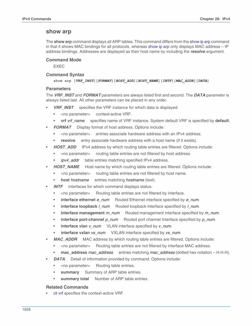
1828
IPv4 Commands Chapter 28: IPv4
show arp
The show arp command displays all ARP tables. This command differs from the show ip arp commandin that it shows MAC bindings for all protocols, whereas show ip arp only displays MAC address – IPaddress bindings. Addresses are displayed as their host name by including the resolve argument.
Command ModeEXEC
Command Syntaxshow arp [VRF_INST][FORMAT][HOST_ADD][HOST_NAME][INTF][MAC_ADDR][DATA]
ParametersThe VRF_INST and FORMAT parameters are always listed first and second. The DATA parameter isalways listed last. All other parameters can be placed in any order.
• VRF_INST specifies the VRF instance for which data is displayed.
• <no parameter> context-active VRF.
• vrf vrf_name specifies name of VRF instance. System default VRF is specified by default.
• FORMAT Display format of host address. Options include:
• <no parameter> entries associate hardware address with an IPv4 address.
• resolve entry associate hardware address with a host name (if it exists).
• HOST_ADD IPv4 address by which routing table entries are filtered. Options include:
• <no parameter> routing table entries are not filtered by host address.
• ipv4_addr table entries matching specified IPv4 address.
• HOST_NAME Host name by which routing table entries are filtered. Options include:
• <no parameter> routing table entries are not filtered by host name.
• host hostname entries matching hostname (text).
• INTF interfaces for which command displays status.
• <no parameter> Routing table entries are not filtered by interface.
• interface ethernet e_num Routed Ethernet interface specified by e_num.
• interface loopback l_num Routed loopback interface specified by l_num.
• interface management m_num Routed management interface specified by m_num.
• interface port-channel p_num Routed port channel Interface specified by p_num.
• interface vlan v_num VLAN interface specified by v_num.
• interface vxlan vx_num VXLAN interface specified by vx_num.
• MAC_ADDR MAC address by which routing table entries are filtered. Options include:
• <no parameter> Routing table entries are not filtered by interface MAC address.
• mac_address mac_address entries matching mac_address (dotted hex notation – H.H.H).
• DATA Detail of information provided by command. Options include:
• <no parameter> Routing table entries.
• summary Summary of ARP table entries.
• summary total Number of ARP table entries.
Related Commands• cli vrf specifies the context-active VRF.

Chapter 28: IPv4 IPv4 Commands
1829
Example• This command displays the ARP table.
switch>show arpAddress Age (min) Hardware Addr Interface172.22.30.1 0 001c.730b.1d15 Management1172.22.30.133 0 001c.7304.3906 Management1switch>
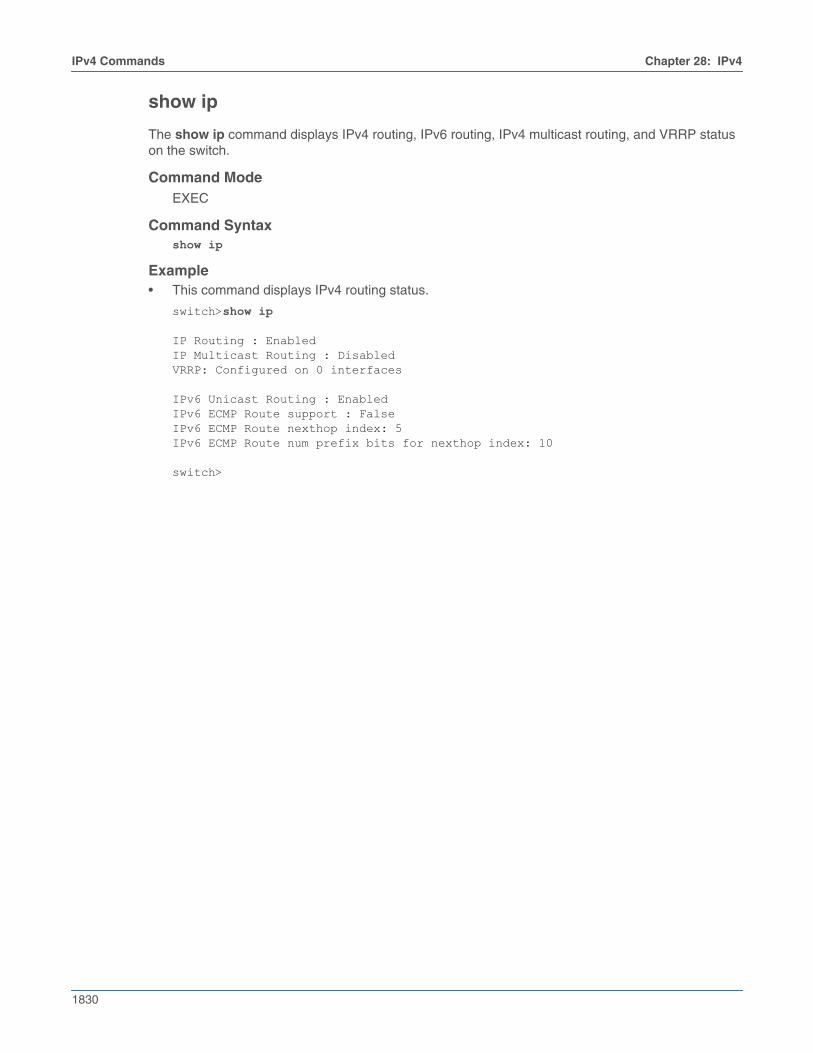
1830
IPv4 Commands Chapter 28: IPv4
show ip
The show ip command displays IPv4 routing, IPv6 routing, IPv4 multicast routing, and VRRP statuson the switch.
Command ModeEXEC
Command Syntaxshow ip
Example• This command displays IPv4 routing status.
switch>show ip
IP Routing : EnabledIP Multicast Routing : DisabledVRRP: Configured on 0 interfaces
IPv6 Unicast Routing : EnabledIPv6 ECMP Route support : FalseIPv6 ECMP Route nexthop index: 5IPv6 ECMP Route num prefix bits for nexthop index: 10
switch>
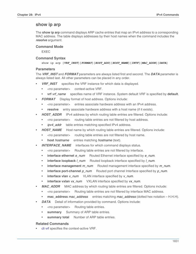
Chapter 28: IPv4 IPv4 Commands
1831
show ip arp
The show ip arp command displays ARP cache entries that map an IPv4 address to a correspondingMAC address. The table displays addresses by their host names when the command includes theresolve argument.
Command ModeEXEC
Command Syntaxshow ip arp [VRF_INST][FORMAT][HOST_ADD][HOST_NAME][INTF][MAC_ADDR][DATA]
ParametersThe VRF_INST and FORMAT parameters are always listed first and second. The DATA parameter isalways listed last. All other parameters can be placed in any order.
• VRF_INST specifies the VRF instance for which data is displayed.
• <no parameter> context-active VRF.
• vrf vrf_name specifies name of VRF instance. System default VRF is specified by default.
• FORMAT Display format of host address. Options include:
• <no parameter> entries associate hardware address with an IPv4 address.
• resolve entry associate hardware address with a host name (if it exists).
• HOST_ADDR IPv4 address by which routing table entries are filtered. Options include:
• <no parameter> routing table entries are not filtered by host address.
• ipv4_addr table entries matching specified IPv4 address.
• HOST_NAME Host name by which routing table entries are filtered. Options include:
• <no parameter> routing table entries are not filtered by host name.
• host hostname entries matching hostname (text).
• INTERFACE_NAME interfaces for which command displays status.
• <no parameter> Routing table entries are not filtered by interface.
• interface ethernet e_num Routed Ethernet interface specified by e_num.
• interface loopback l_num Routed loopback interface specified by l_num.
• interface management m_num Routed management interface specified by m_num.
• interface port-channel p_num Routed port channel Interface specified by p_num.
• interface vlan v_num VLAN interface specified by v_num.
• interface vxlan vx_num VXLAN interface specified by vx_num.
• MAC_ADDR MAC address by which routing table entries are filtered. Options include:
• <no parameter> Routing table entries are not filtered by interface MAC address.
• mac_address mac_address entries matching mac_address (dotted hex notation – H.H.H).
• DATA Detail of information provided by command. Options include:
• <no parameter> Routing table entries.
• summary Summary of ARP table entries.
• summary total Number of ARP table entries.
Related Commands• cli vrf specifies the context-active VRF.

1832
IPv4 Commands Chapter 28: IPv4
Examples• This command displays ARP cache entries that map MAC addresses to IPv4 addresses.
switch>show ip arpAddress Age (min) Hardware Addr Interface172.25.0.2 0 004c.6211.021e Vlan101, Port-Channel2172.22.0.1 0 004c.6214.3699 Vlan1000, Port-Channel1172.22.0.2 0 004c.6219.a0f3 Vlan1000, Port-Channel1172.22.0.3 0 0045.4942.a32c Vlan1000, Ethernet33172.22.0.5 0 f012.3118.c09d Vlan1000, Port-Channel1172.22.0.6 0 00e1.d11a.a1eb Vlan1000, Ethernet5172.22.0.7 0 004f.e320.cd23 Vlan1000, Ethernet6172.22.0.8 0 0032.48da.f9d9 Vlan1000, Ethernet37172.22.0.9 0 0018.910a.1fc5 Vlan1000, Ethernet29172.22.0.11 0 0056.cbe9.8510 Vlan1000, Ethernet26switch>
• This command displays ARP cache entries that map MAC addresses to IPv4 addresses. Hostnames assigned to IP addresses are displayed in place of the address.
switch>show ip arp resolveAddress Age (min) Hardware Addr Interfacegreen-vl101.new 0 004c.6211.021e Vlan101, Port-Channel2172.22.0.1 0 004c.6214.3699 Vlan1000, Port-Channel1orange-vl1000.n 0 004c.6219.a0f3 Vlan1000, Port-Channel1172.22.0.3 0 0045.4942.a32c Vlan1000, Ethernet33purple.newcompa 0 f012.3118.c09d Vlan1000, Port-Channel1pink.newcompany 0 00e1.d11a.a1eb Vlan1000, Ethernet5yellow.newcompa 0 004f.e320.cd23 Vlan1000, Ethernet6172.22.0.8 0 0032.48da.f9d9 Vlan1000, Ethernet37royalblue.newco 0 0018.910a.1fc5 Vlan1000, Ethernet29172.22.0.11 0 0056.cbe9.8510 Vlan1000, Ethernet26switch>
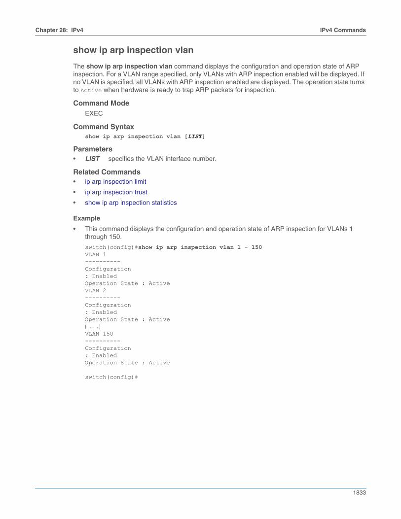
Chapter 28: IPv4 IPv4 Commands
1833
show ip arp inspection vlan
The show ip arp inspection vlan command displays the configuration and operation state of ARPinspection. For a VLAN range specified, only VLANs with ARP inspection enabled will be displayed. Ifno VLAN is specified, all VLANs with ARP inspection enabled are displayed. The operation state turnsto Active when hardware is ready to trap ARP packets for inspection.
Command ModeEXEC
Command Syntaxshow ip arp inspection vlan [LIST]
Parameters• LIST specifies the VLAN interface number.
Related Commands• ip arp inspection limit
• ip arp inspection trust
• show ip arp inspection statistics
Example
• This command displays the configuration and operation state of ARP inspection for VLANs 1through 150.
switch(config)#show ip arp inspection vlan 1 - 150VLAN 1----------Configuration: EnabledOperation State : ActiveVLAN 2----------Configuration: EnabledOperation State : Active{...}VLAN 150----------Configuration: EnabledOperation State : Active
switch(config)#
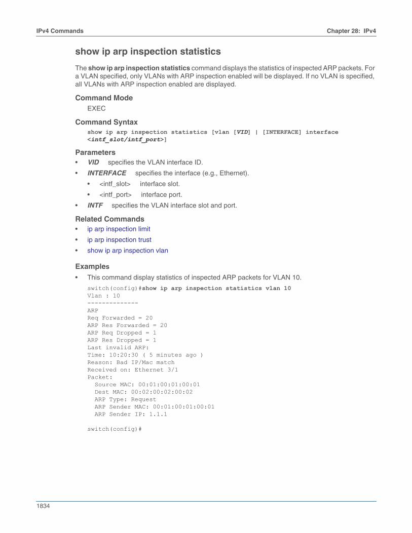
1834
IPv4 Commands Chapter 28: IPv4
show ip arp inspection statistics
The show ip arp inspection statistics command displays the statistics of inspected ARP packets. Fora VLAN specified, only VLANs with ARP inspection enabled will be displayed. If no VLAN is specified,all VLANs with ARP inspection enabled are displayed.
Command ModeEXEC
Command Syntaxshow ip arp inspection statistics [vlan [VID] | [INTERFACE] interface <intf_slot/intf_port>]
Parameters• VID specifies the VLAN interface ID.
• INTERFACE specifies the interface (e.g., Ethernet).
• <intf_slot> interface slot.
• <intf_port> interface port.
• INTF specifies the VLAN interface slot and port.
Related Commands• ip arp inspection limit
• ip arp inspection trust
• show ip arp inspection vlan
Examples
• This command display statistics of inspected ARP packets for VLAN 10.
switch(config)#show ip arp inspection statistics vlan 10Vlan : 10--------------ARPReq Forwarded = 20ARP Res Forwarded = 20ARP Req Dropped = 1ARP Res Dropped = 1Last invalid ARP:Time: 10:20:30 ( 5 minutes ago )Reason: Bad IP/Mac matchReceived on: Ethernet 3/1Packet: Source MAC: 00:01:00:01:00:01 Dest MAC: 00:02:00:02:00:02 ARP Type: Request ARP Sender MAC: 00:01:00:01:00:01 ARP Sender IP: 1.1.1
switch(config)#
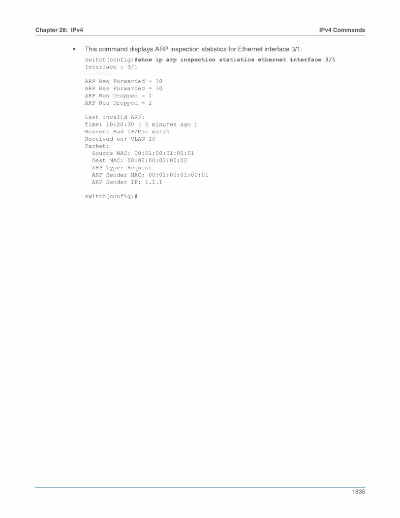
Chapter 28: IPv4 IPv4 Commands
1835
• This command displays ARP inspection statistics for Ethernet interface 3/1.
switch(config)#show ip arp inspection statistics ethernet interface 3/1Interface : 3/1--------ARP Req Forwarded = 10ARP Res Forwarded = 10ARP Req Dropped = 1ARP Res Dropped = 1
Last invalid ARP:Time: 10:20:30 ( 5 minutes ago )Reason: Bad IP/Mac matchReceived on: VLAN 10Packet: Source MAC: 00:01:00:01:00:01 Dest MAC: 00:02:00:02:00:02 ARP Type: Request ARP Sender MAC: 00:01:00:01:00:01 ARP Sender IP: 1.1.1
switch(config)#

1836
IPv4 Commands Chapter 28: IPv4
show ip dhcp relay
The show ip dhcp relay command displays the DHCP relay agent configuration status on the switch.
Command ModeEXEC
Command Syntaxshow ip dhcp relay
Example• This command displays the DHCP relay agent configuration status.
switch>show ip dhcp relayDHCP Relay is activeDHCP Relay Option 82 is disabledDHCP Smart Relay is enabledInterface: Vlan100 DHCP Smart Relay is disabled DHCP servers: 10.4.4.4switch>
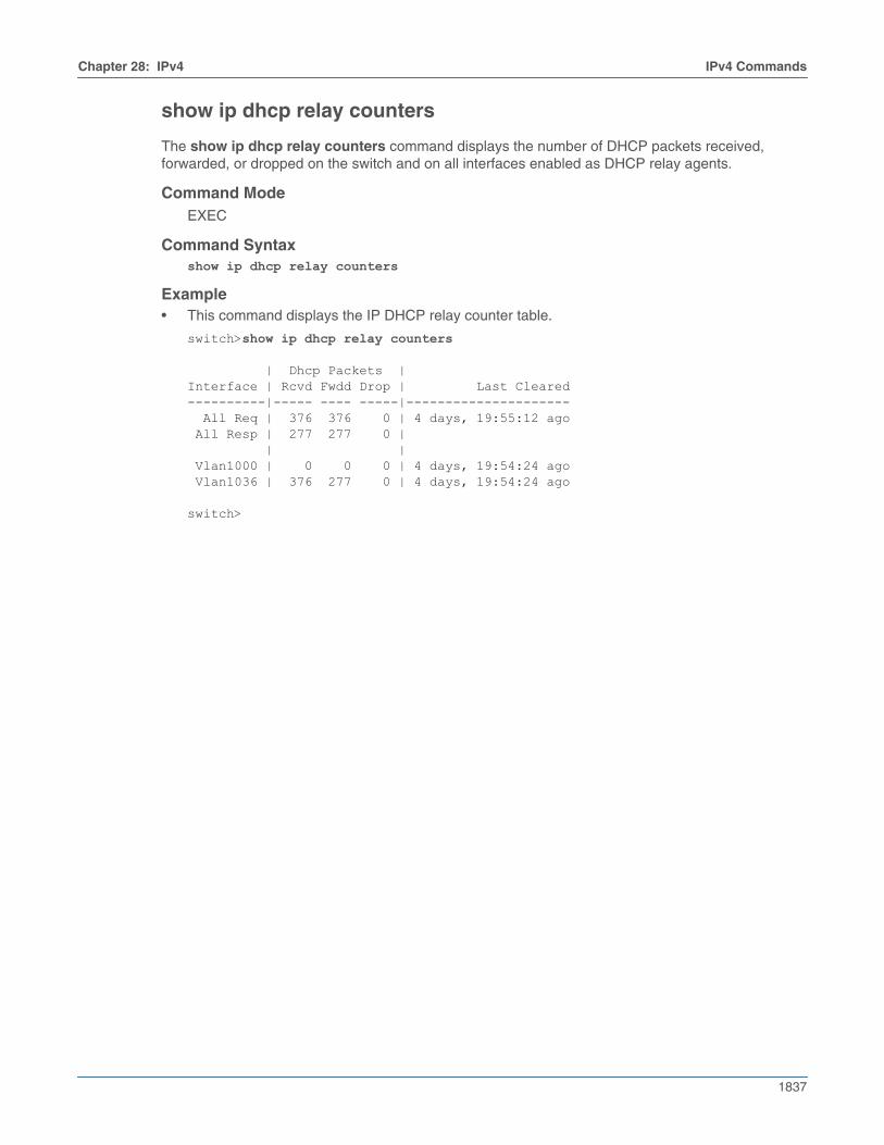
Chapter 28: IPv4 IPv4 Commands
1837
show ip dhcp relay counters
The show ip dhcp relay counters command displays the number of DHCP packets received,forwarded, or dropped on the switch and on all interfaces enabled as DHCP relay agents.
Command ModeEXEC
Command Syntaxshow ip dhcp relay counters
Example• This command displays the IP DHCP relay counter table.
switch>show ip dhcp relay counters
| Dhcp Packets |Interface | Rcvd Fwdd Drop | Last Cleared----------|----- ---- -----|--------------------- All Req | 376 376 0 | 4 days, 19:55:12 ago All Resp | 277 277 0 | | | Vlan1000 | 0 0 0 | 4 days, 19:54:24 ago Vlan1036 | 376 277 0 | 4 days, 19:54:24 ago
switch>

1838
IPv4 Commands Chapter 28: IPv4
show ip dhcp snooping
The show ip dhcp snooping command displays the DHCP snooping configuration.
Command ModeEXEC
Command Syntaxshow ip dhcp snooping
Related Commands• ip dhcp snooping globally enables DHCP snooping.
• ip dhcp snooping vlan enables DHCP snooping on specified VLANs.
• ip dhcp snooping information option enables insertion of option-82 snooping data.
• ip helper-address enables the DHCP relay agent on a configuration mode interface.
Example• This command displays the switch’s DHCP snooping configuration.
switch>show ip dhcp snoopingDHCP Snooping is enabledDHCP Snooping is operationalDHCP Snooping is configured on following VLANs: 100DHCP Snooping is operational on following VLANs: 100Insertion of Option-82 is enabled Circuit-id format: Interface name:Vlan ID Remote-id: 00:1c:73:1f:b4:38 (Switch MAC)switch>
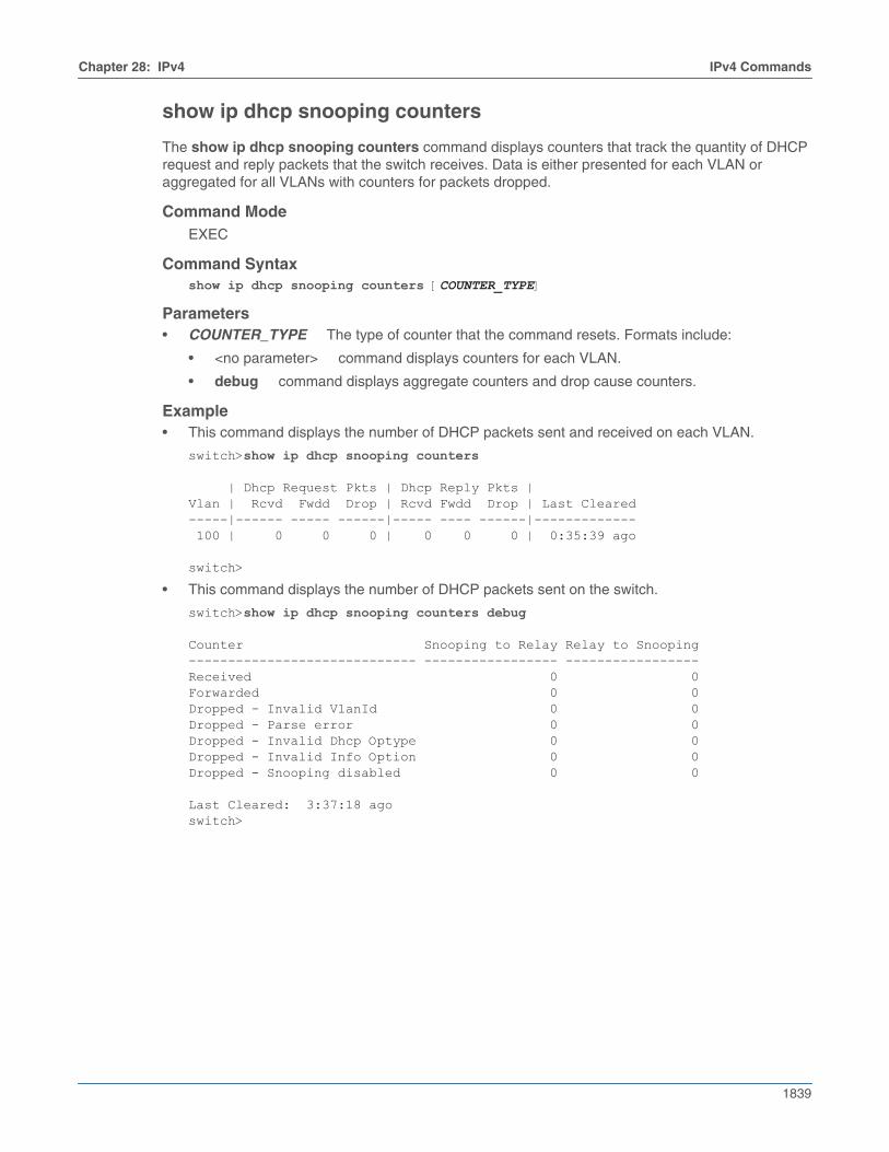
Chapter 28: IPv4 IPv4 Commands
1839
show ip dhcp snooping counters
The show ip dhcp snooping counters command displays counters that track the quantity of DHCPrequest and reply packets that the switch receives. Data is either presented for each VLAN oraggregated for all VLANs with counters for packets dropped.
Command ModeEXEC
Command Syntaxshow ip dhcp snooping counters [COUNTER_TYPE]
Parameters• COUNTER_TYPE The type of counter that the command resets. Formats include:
• <no parameter> command displays counters for each VLAN.
• debug command displays aggregate counters and drop cause counters.
Example• This command displays the number of DHCP packets sent and received on each VLAN.
switch>show ip dhcp snooping counters
| Dhcp Request Pkts | Dhcp Reply Pkts |Vlan | Rcvd Fwdd Drop | Rcvd Fwdd Drop | Last Cleared-----|------ ----- ------|----- ---- ------|------------- 100 | 0 0 0 | 0 0 0 | 0:35:39 ago
switch>
• This command displays the number of DHCP packets sent on the switch.
switch>show ip dhcp snooping counters debug
Counter Snooping to Relay Relay to Snooping----------------------------- ----------------- -----------------Received 0 0Forwarded 0 0Dropped - Invalid VlanId 0 0Dropped - Parse error 0 0Dropped - Invalid Dhcp Optype 0 0Dropped - Invalid Info Option 0 0Dropped - Snooping disabled 0 0
Last Cleared: 3:37:18 agoswitch>
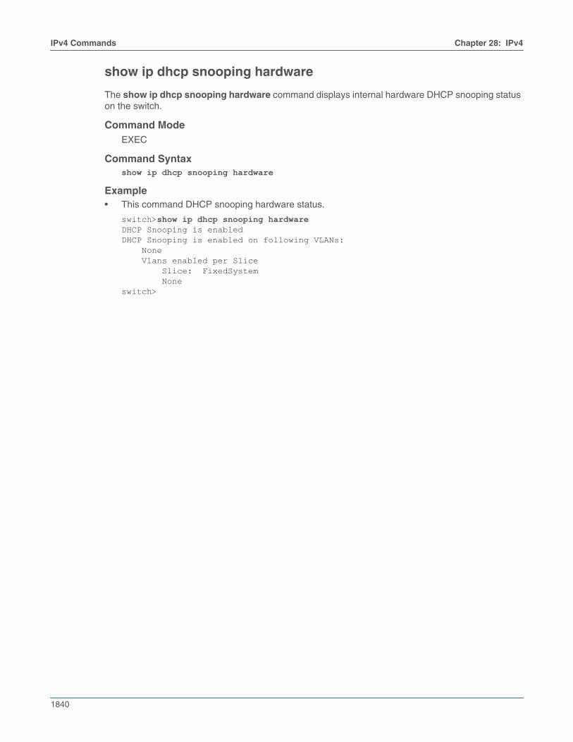
1840
IPv4 Commands Chapter 28: IPv4
show ip dhcp snooping hardware
The show ip dhcp snooping hardware command displays internal hardware DHCP snooping statuson the switch.
Command ModeEXEC
Command Syntaxshow ip dhcp snooping hardware
Example• This command DHCP snooping hardware status.
switch>show ip dhcp snooping hardwareDHCP Snooping is enabledDHCP Snooping is enabled on following VLANs: None Vlans enabled per Slice Slice: FixedSystem Noneswitch>
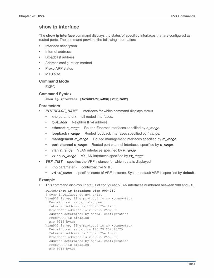
Chapter 28: IPv4 IPv4 Commands
1841
show ip interface
The show ip interface command displays the status of specified interfaces that are configured asrouted ports. The command provides the following information:
• Interface description
• Internet address
• Broadcast address
• Address configuration method
• Proxy-ARP status
• MTU size
Command ModeEXEC
Command Syntaxshow ip interface [INTERFACE_NAME][VRF_INST]
Parameters• INTERFACE_NAME interfaces for which command displays status.
• <no parameter> all routed interfaces.
• ipv4_addr Neighbor IPv4 address.
• ethernet e_range Routed Ethernet interfaces specified by e_range.
• loopback l_range Routed loopback interfaces specified by l_range.
• management m_range Routed management interfaces specified by m_range.
• port-channel p_range Routed port channel Interfaces specified by p_range.
• vlan v_range VLAN interfaces specified by v_range.
• vxlan vx_range VXLAN interfaces specified by vx_range.
• VRF_INST specifies the VRF instance for which data is displayed.
• <no parameter> context-active VRF.
• vrf vrf_name specifies name of VRF instance. System default VRF is specified by default.
Example• This command displays IP status of configured VLAN interfaces numbered between 900 and 910.
switch>show ip interface vlan 900-910! Some interfaces do not existVlan901 is up, line protocol is up (connected) Description: ar.pqt.mlag.peer Internet address is 170.23.254.1/30 Broadcast address is 255.255.255.255 Address determined by manual configuration Proxy-ARP is disabled MTU 9212 bytesVlan903 is up, line protocol is up (connected) Description: ar.pqt.rn.170.23.254.16/29 Internet address is 170.23.254.19/29 Broadcast address is 255.255.255.255 Address determined by manual configuration Proxy-ARP is disabled MTU 9212 bytes
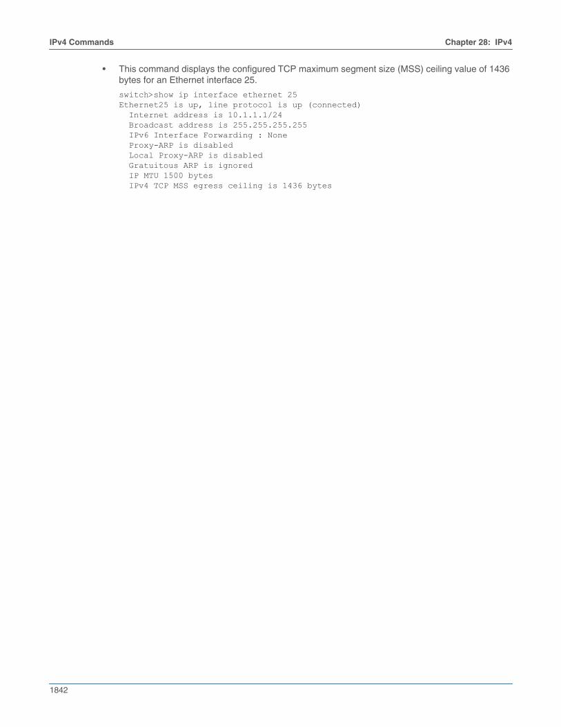
1842
IPv4 Commands Chapter 28: IPv4
• This command displays the configured TCP maximum segment size (MSS) ceiling value of 1436bytes for an Ethernet interface 25.
switch>show ip interface ethernet 25Ethernet25 is up, line protocol is up (connected) Internet address is 10.1.1.1/24 Broadcast address is 255.255.255.255 IPv6 Interface Forwarding : None Proxy-ARP is disabled Local Proxy-ARP is disabled Gratuitous ARP is ignored IP MTU 1500 bytes IPv4 TCP MSS egress ceiling is 1436 bytes
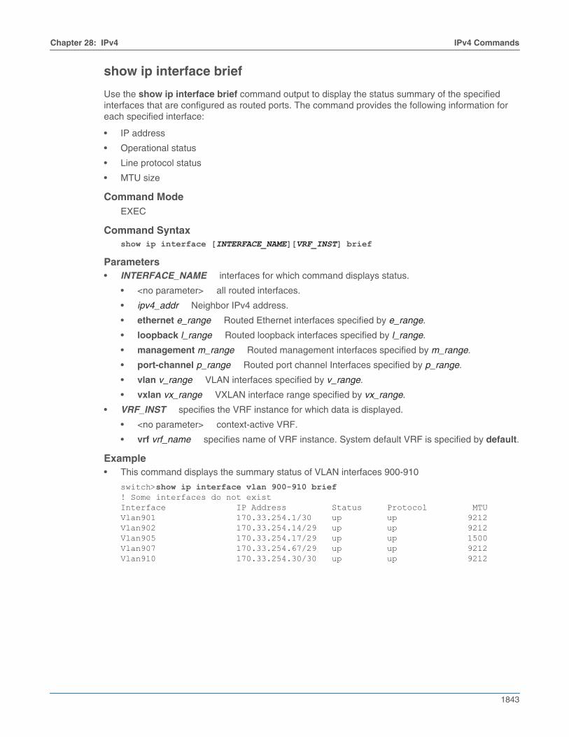
Chapter 28: IPv4 IPv4 Commands
1843
show ip interface brief
Use the show ip interface brief command output to display the status summary of the specifiedinterfaces that are configured as routed ports. The command provides the following information foreach specified interface:
• IP address
• Operational status
• Line protocol status
• MTU size
Command ModeEXEC
Command Syntaxshow ip interface [INTERFACE_NAME][VRF_INST] brief
Parameters• INTERFACE_NAME interfaces for which command displays status.
• <no parameter> all routed interfaces.
• ipv4_addr Neighbor IPv4 address.
• ethernet e_range Routed Ethernet interfaces specified by e_range.
• loopback l_range Routed loopback interfaces specified by l_range.
• management m_range Routed management interfaces specified by m_range.
• port-channel p_range Routed port channel Interfaces specified by p_range.
• vlan v_range VLAN interfaces specified by v_range.
• vxlan vx_range VXLAN interface range specified by vx_range.
• VRF_INST specifies the VRF instance for which data is displayed.
• <no parameter> context-active VRF.
• vrf vrf_name specifies name of VRF instance. System default VRF is specified by default.
Example• This command displays the summary status of VLAN interfaces 900-910
switch>show ip interface vlan 900-910 brief! Some interfaces do not existInterface IP Address Status Protocol MTUVlan901 170.33.254.1/30 up up 9212Vlan902 170.33.254.14/29 up up 9212Vlan905 170.33.254.17/29 up up 1500Vlan907 170.33.254.67/29 up up 9212Vlan910 170.33.254.30/30 up up 9212
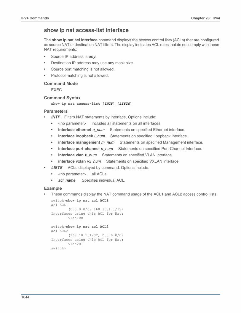
1844
IPv4 Commands Chapter 28: IPv4
show ip nat access-list interface
The show ip nat acl interface command displays the access control lists (ACLs) that are configuredas source NAT or destination NAT filters. The display indicates ACL rules that do not comply with theseNAT requirements:
• Source IP address is any.
• Destination IP address may use any mask size.
• Source port matching is not allowed.
• Protocol matching is not allowed.
Command ModeEXEC
Command Syntaxshow ip nat access-list [INTF] [LISTS]
Parameters• INTF Filters NAT statements by interface. Options include:
• <no parameter> includes all statements on all interfaces.
• interface ethernet e_num Statements on specified Ethernet interface.
• interface loopback l_num Statements on specified Loopback interface.
• interface management m_num Statements on specified Management interface.
• interface port-channel p_num Statements on specified Port-Channel Interface.
• interface vlan v_num Statements on specified VLAN interface.
• interface vxlan vx_num Statements on specified VXLAN interface.
• LISTS ACLs displayed by command. Options include:
• <no parameter> all ACLs.
• acl_name Specifies individual ACL.
Example• These commands display the NAT command usage of the ACL1 and ACL2 access control lists.
switch>show ip nat acl ACL1acl ACL1 (0.0.0.0/0, 168.10.1.1/32)Interfaces using this ACL for Nat: Vlan100
switch>show ip nat acl ACL2acl ACL2 (168.10.1.1/32, 0.0.0.0/0)Interfaces using this ACL for Nat: Vlan201switch>
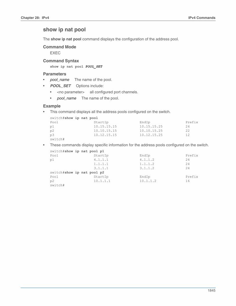
Chapter 28: IPv4 IPv4 Commands
1845
show ip nat pool
The show ip nat pool command displays the configuration of the address pool.
Command ModeEXEC
Command Syntaxshow ip nat pool POOL_SET
Parameters• pool_name The name of the pool.
• POOL_SET Options include:
• <no parameter> all configured port channels.
• pool_name The name of the pool.
Example• This command displays all the address pools configured on the switch.
switch#show ip nat poolPool StartIp EndIp Prefixp1 10.15.15.15 10.15.15.25 24p2 10.10.15.15 10.10.15.25 22p3 10.12.15.15 10.12.15.25 12switch#
• These commands display specific information for the address pools configured on the switch.
switch#show ip nat pool p1Pool StartIp EndIp Prefixp1 4.1.1.1 4.1.1.2 24 1.1.1.1 1.1.1.2 24 3.1.1.1 3.1.1.2 24switch#show ip nat pool p2Pool StartIp EndIp Prefixp2 10.1.1.1 10.1.1.2 16switch#
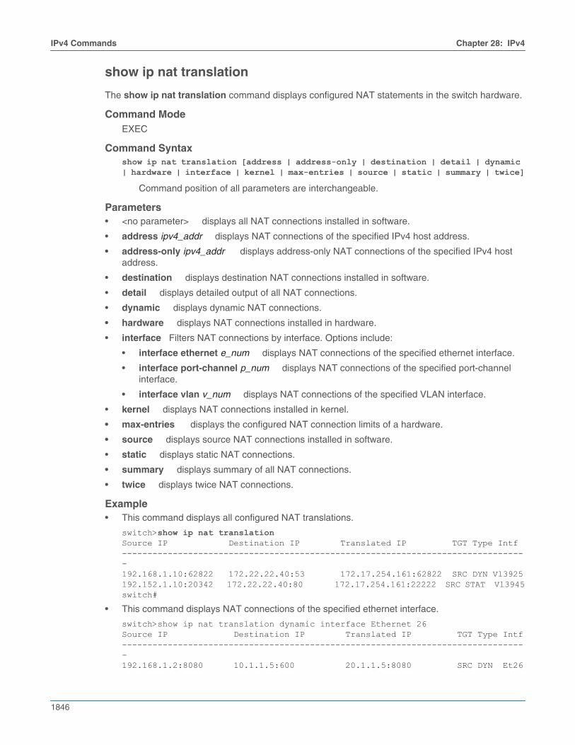
1846
IPv4 Commands Chapter 28: IPv4
show ip nat translation
The show ip nat translation command displays configured NAT statements in the switch hardware.
Command ModeEXEC
Command Syntaxshow ip nat translation [address | address-only | destination | detail | dynamic | hardware | interface | kernel | max-entries | source | static | summary | twice]
Command position of all parameters are interchangeable.
Parameters• <no parameter> displays all NAT connections installed in software.
• address ipv4_addr displays NAT connections of the specified IPv4 host address.
• address-only ipv4_addr displays address-only NAT connections of the specified IPv4 hostaddress.
• destination displays destination NAT connections installed in software.
• detail displays detailed output of all NAT connections.
• dynamic displays dynamic NAT connections.
• hardware displays NAT connections installed in hardware.
• interface Filters NAT connections by interface. Options include:
• interface ethernet e_num displays NAT connections of the specified ethernet interface.
• interface port-channel p_num displays NAT connections of the specified port-channelinterface.
• interface vlan v_num displays NAT connections of the specified VLAN interface.
• kernel displays NAT connections installed in kernel.
• max-entries displays the configured NAT connection limits of a hardware.
• source displays source NAT connections installed in software.
• static displays static NAT connections.
• summary displays summary of all NAT connections.
• twice displays twice NAT connections.
Example• This command displays all configured NAT translations.
switch>show ip nat translationSource IP Destination IP Translated IP TGT Type Intf--------------------------------------------------------------------------------192.168.1.10:62822 172.22.22.40:53 172.17.254.161:62822 SRC DYN Vl3925192.152.1.10:20342 172.22.22.40:80 172.17.254.161:22222 SRC STAT Vl3945switch#
• This command displays NAT connections of the specified ethernet interface.
switch>show ip nat translation dynamic interface Ethernet 26Source IP Destination IP Translated IP TGT Type Intf--------------------------------------------------------------------------------192.168.1.2:8080 10.1.1.5:600 20.1.1.5:8080 SRC DYN Et26
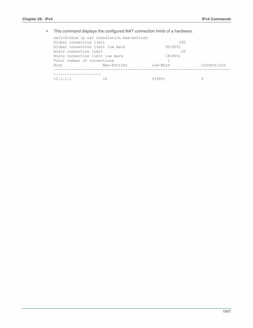
Chapter 28: IPv4 IPv4 Commands
1847
• This command displays the configured NAT connection limits of a hardware.
switch>show ip nat translation max-entriesGlobal connection limit 100Global connection limit low mark 90(90%)Hosts connection limit 20Hosts connection limit low mark 18(90%)Total number of connections 1Host Max-Entries Low-Mark Connections----------------------------------------------------------------------------------------------------10.1.1.1 10 9(90%) 0
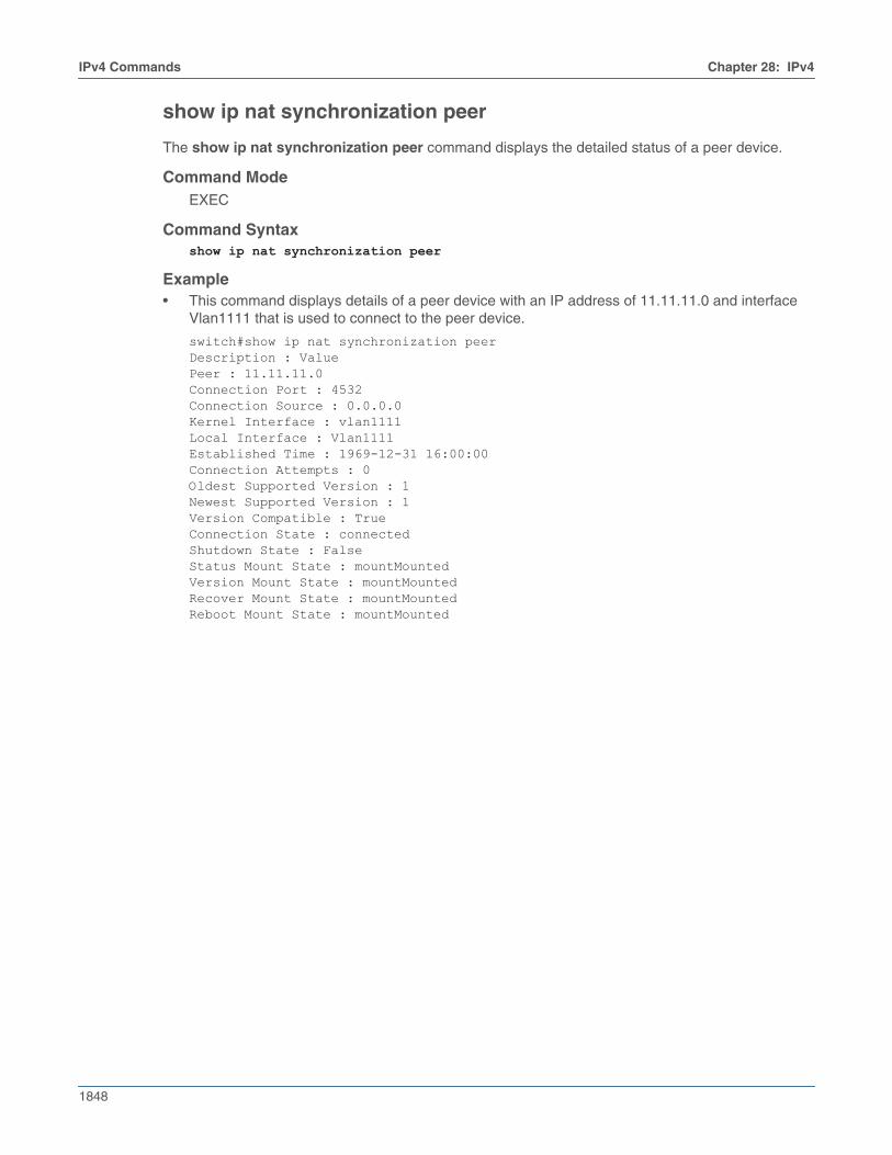
1848
IPv4 Commands Chapter 28: IPv4
show ip nat synchronization peer
The show ip nat synchronization peer command displays the detailed status of a peer device.
Command ModeEXEC
Command Syntaxshow ip nat synchronization peer
Example• This command displays details of a peer device with an IP address of 11.11.11.0 and interface
Vlan1111 that is used to connect to the peer device.
switch#show ip nat synchronization peerDescription : ValuePeer : 11.11.11.0Connection Port : 4532Connection Source : 0.0.0.0Kernel Interface : vlan1111Local Interface : Vlan1111Established Time : 1969-12-31 16:00:00Connection Attempts : 0Oldest Supported Version : 1Newest Supported Version : 1Version Compatible : TrueConnection State : connectedShutdown State : FalseStatus Mount State : mountMountedVersion Mount State : mountMountedRecover Mount State : mountMountedReboot Mount State : mountMounted
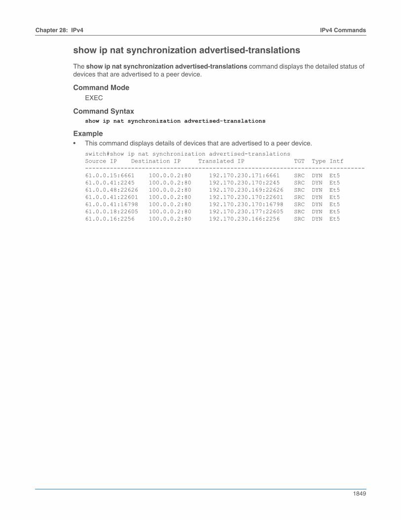
Chapter 28: IPv4 IPv4 Commands
1849
show ip nat synchronization advertised-translations
The show ip nat synchronization advertised-translations command displays the detailed status ofdevices that are advertised to a peer device.
Command ModeEXEC
Command Syntaxshow ip nat synchronization advertised-translations
Example• This command displays details of devices that are advertised to a peer device.
switch#show ip nat synchronization advertised-translationsSource IP Destination IP Translated IP TGT Type Intf-------------------------------------------------------------------------------61.0.0.15:6661 100.0.0.2:80 192.170.230.171:6661 SRC DYN Et561.0.0.41:2245 100.0.0.2:80 192.170.230.170:2245 SRC DYN Et561.0.0.48:22626 100.0.0.2:80 192.170.230.169:22626 SRC DYN Et561.0.0.41:22601 100.0.0.2:80 192.170.230.170:22601 SRC DYN Et561.0.0.41:16798 100.0.0.2:80 192.170.230.170:16798 SRC DYN Et561.0.0.18:22605 100.0.0.2:80 192.170.230.177:22605 SRC DYN Et561.0.0.16:2256 100.0.0.2:80 192.170.230.166:2256 SRC DYN Et5
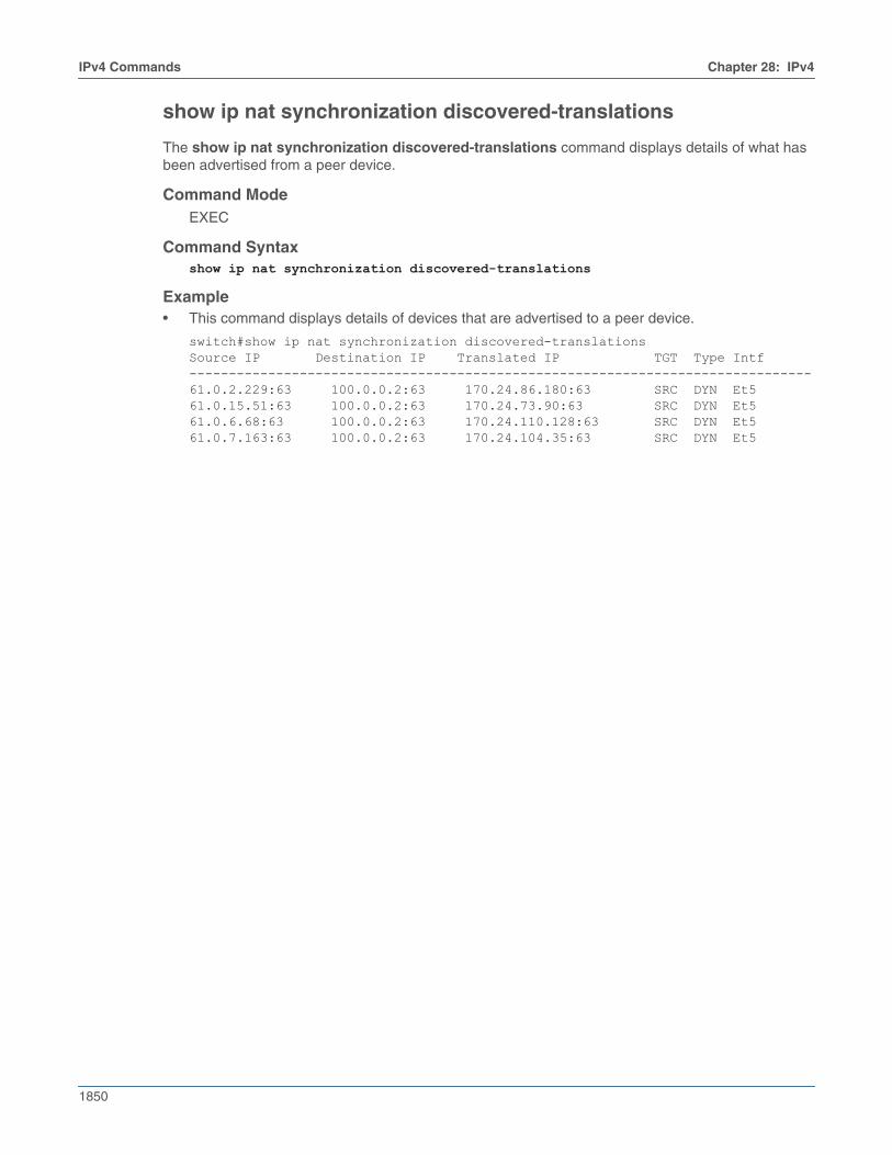
1850
IPv4 Commands Chapter 28: IPv4
show ip nat synchronization discovered-translations
The show ip nat synchronization discovered-translations command displays details of what hasbeen advertised from a peer device.
Command ModeEXEC
Command Syntaxshow ip nat synchronization discovered-translations
Example• This command displays details of devices that are advertised to a peer device.
switch#show ip nat synchronization discovered-translationsSource IP Destination IP Translated IP TGT Type Intf-------------------------------------------------------------------------------61.0.2.229:63 100.0.0.2:63 170.24.86.180:63 SRC DYN Et561.0.15.51:63 100.0.0.2:63 170.24.73.90:63 SRC DYN Et561.0.6.68:63 100.0.0.2:63 170.24.110.128:63 SRC DYN Et561.0.7.163:63 100.0.0.2:63 170.24.104.35:63 SRC DYN Et5

Chapter 28: IPv4 IPv4 Commands
1851
show ip route
The show ip route command displays routing table entries that are in the Forwarding Information Base(FIB), including static routes, routes to directly connected networks, and dynamically learned routes.Multiple equal-cost paths to the same prefix are displayed contiguously as a block, with the destinationprefix displayed only on the first line.
The show running-config command displays configured commands not in the FIB.
Command ModeEXEC
Command Syntaxshow ip route [VRF_INSTANCE][ADDRESS][ROUTE_TYPE][INFO_LEVEL][PREFIX]
ParametersThe VRF_INSTANCE and ADDRESS parameters are always listed first and second, respectively. Allother parameters can be placed in any order.
• VRF_INSTANCE specifies the VRF instance for which data is displayed.
• <no parameter> context-active VRF.
• vrf vrf_name specifies name of VRF instance. System default VRF is specified by default.
• ADDRESS Filters routes by IPv4 address or subnet.
• <no parameter> all routing table entries.
• ipv4_addr routing table entries matching specified address.
• ipv4_subnet routing table entries matching specified subnet (CIDR or address-mask).
• ROUTE_TYPE Filters routes by specified protocol or origin. Options include:
• <no parameter> all routing table entries.
• aggregate entries for BGP aggregate routes.
• bgp entries added through BGP protocol.
• connected entries for routes to networks directly connected to the switch.
• isis entries added through ISIS protocol.
• kernel entries appearing in Linux kernel but not added by EOS software.
• ospf entries added through OSPF protocol.
• rip entries added through RIP protocol.
• static entries added through CLI commands.
• vrf displays routes in a VRF.
• INFO_LEVEL Filters entries by next hop connection. Options include:
• <no parameter> filters routes whose next hops are directly connected.
• detail displays all routes.
• PREFIX filters routes by prefix.
• <no parameter> specific route entry that matches the ADDRESS parameter.
• longer-prefixes all subnet route entries in range specified by ADDRESS parameter.
Related Commands• cli vrf specifies the context-active VRF.
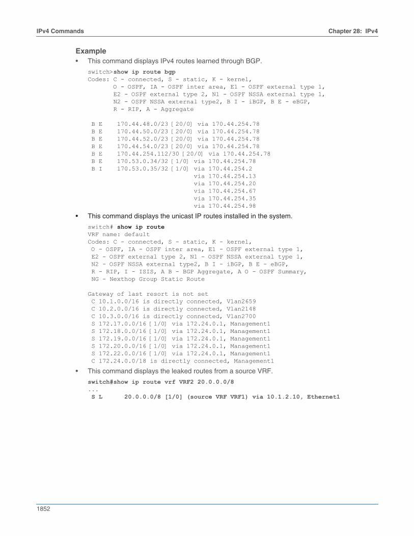
1852
IPv4 Commands Chapter 28: IPv4
Example• This command displays IPv4 routes learned through BGP.
switch>show ip route bgpCodes: C - connected, S - static, K - kernel, O - OSPF, IA - OSPF inter area, E1 - OSPF external type 1, E2 - OSPF external type 2, N1 - OSPF NSSA external type 1, N2 - OSPF NSSA external type2, B I - iBGP, B E - eBGP, R - RIP, A - Aggregate
B E 170.44.48.0/23 [20/0] via 170.44.254.78 B E 170.44.50.0/23 [20/0] via 170.44.254.78 B E 170.44.52.0/23 [20/0] via 170.44.254.78 B E 170.44.54.0/23 [20/0] via 170.44.254.78 B E 170.44.254.112/30 [20/0] via 170.44.254.78 B E 170.53.0.34/32 [1/0] via 170.44.254.78 B I 170.53.0.35/32 [1/0] via 170.44.254.2 via 170.44.254.13 via 170.44.254.20 via 170.44.254.67 via 170.44.254.35 via 170.44.254.98
• This command displays the unicast IP routes installed in the system.
switch# show ip routeVRF name: defaultCodes: C - connected, S - static, K - kernel, O - OSPF, IA - OSPF inter area, E1 - OSPF external type 1, E2 - OSPF external type 2, N1 - OSPF NSSA external type 1, N2 - OSPF NSSA external type2, B I - iBGP, B E - eBGP, R - RIP, I - ISIS, A B - BGP Aggregate, A O - OSPF Summary, NG - Nexthop Group Static Route
Gateway of last resort is not set C 10.1.0.0/16 is directly connected, Vlan2659 C 10.2.0.0/16 is directly connected, Vlan2148 C 10.3.0.0/16 is directly connected, Vlan2700 S 172.17.0.0/16 [1/0] via 172.24.0.1, Management1 S 172.18.0.0/16 [1/0] via 172.24.0.1, Management1 S 172.19.0.0/16 [1/0] via 172.24.0.1, Management1 S 172.20.0.0/16 [1/0] via 172.24.0.1, Management1 S 172.22.0.0/16 [1/0] via 172.24.0.1, Management1 C 172.24.0.0/18 is directly connected, Management1
• This command displays the leaked routes from a source VRF.
switch#show ip route vrf VRF2 20.0.0.0/8... S L 20.0.0.0/8 [1/0] (source VRF VRF1) via 10.1.2.10, Ethernet1
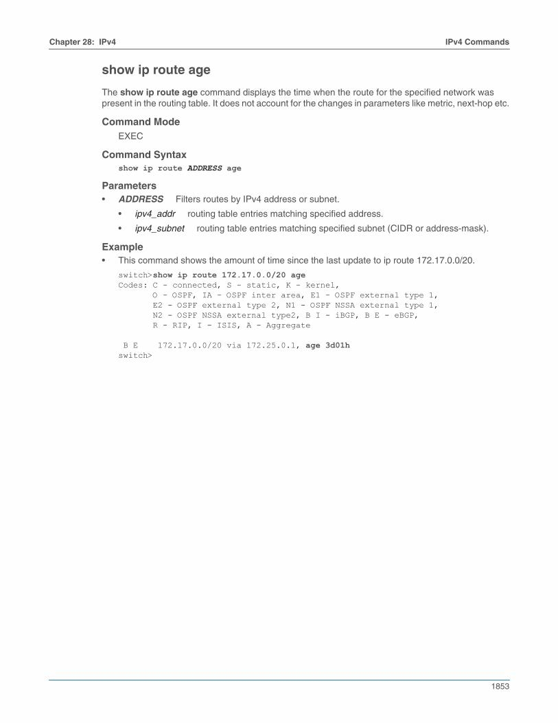
Chapter 28: IPv4 IPv4 Commands
1853
show ip route age
The show ip route age command displays the time when the route for the specified network waspresent in the routing table. It does not account for the changes in parameters like metric, next-hop etc.
Command ModeEXEC
Command Syntaxshow ip route ADDRESS age
Parameters• ADDRESS Filters routes by IPv4 address or subnet.
• ipv4_addr routing table entries matching specified address.
• ipv4_subnet routing table entries matching specified subnet (CIDR or address-mask).
Example• This command shows the amount of time since the last update to ip route 172.17.0.0/20.
switch>show ip route 172.17.0.0/20 ageCodes: C - connected, S - static, K - kernel, O - OSPF, IA - OSPF inter area, E1 - OSPF external type 1, E2 - OSPF external type 2, N1 - OSPF NSSA external type 1, N2 - OSPF NSSA external type2, B I - iBGP, B E - eBGP, R - RIP, I - ISIS, A - Aggregate
B E 172.17.0.0/20 via 172.25.0.1, age 3d01hswitch>
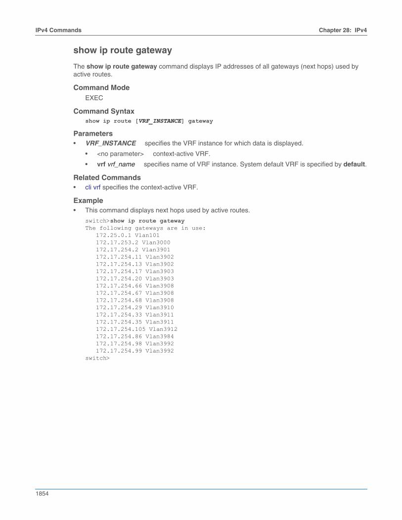
1854
IPv4 Commands Chapter 28: IPv4
show ip route gateway
The show ip route gateway command displays IP addresses of all gateways (next hops) used byactive routes.
Command ModeEXEC
Command Syntaxshow ip route [VRF_INSTANCE] gateway
Parameters• VRF_INSTANCE specifies the VRF instance for which data is displayed.
• <no parameter> context-active VRF.
• vrf vrf_name specifies name of VRF instance. System default VRF is specified by default.
Related Commands• cli vrf specifies the context-active VRF.
Example• This command displays next hops used by active routes.
switch>show ip route gatewayThe following gateways are in use: 172.25.0.1 Vlan101 172.17.253.2 Vlan3000 172.17.254.2 Vlan3901 172.17.254.11 Vlan3902 172.17.254.13 Vlan3902 172.17.254.17 Vlan3903 172.17.254.20 Vlan3903 172.17.254.66 Vlan3908 172.17.254.67 Vlan3908 172.17.254.68 Vlan3908 172.17.254.29 Vlan3910 172.17.254.33 Vlan3911 172.17.254.35 Vlan3911 172.17.254.105 Vlan3912 172.17.254.86 Vlan3984 172.17.254.98 Vlan3992 172.17.254.99 Vlan3992switch>
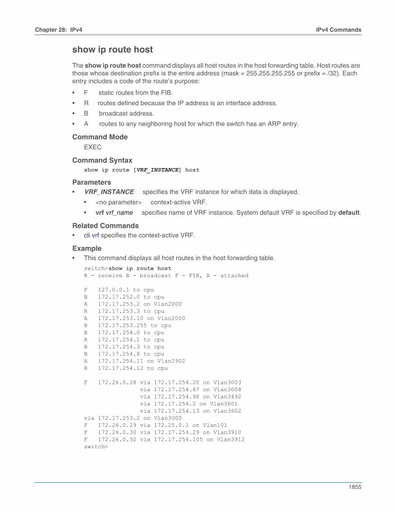
Chapter 28: IPv4 IPv4 Commands
1855
show ip route host
The show ip route host command displays all host routes in the host forwarding table. Host routes arethose whose destination prefix is the entire address (mask = 255.255.255.255 or prefix = /32). Eachentry includes a code of the route’s purpose:
• F static routes from the FIB.
• R routes defined because the IP address is an interface address.
• B broadcast address.
• A routes to any neighboring host for which the switch has an ARP entry.
Command ModeEXEC
Command Syntaxshow ip route [VRF_INSTANCE] host
Parameters• VRF_INSTANCE specifies the VRF instance for which data is displayed.
• <no parameter> context-active VRF.
• vrf vrf_name specifies name of VRF instance. System default VRF is specified by default.
Related Commands• cli vrf specifies the context-active VRF.
Example• This command displays all host routes in the host forwarding table.
switch>show ip route hostR - receive B - broadcast F - FIB, A - attached
F 127.0.0.1 to cpuB 172.17.252.0 to cpuA 172.17.253.2 on Vlan2000R 172.17.253.3 to cpuA 172.17.253.10 on Vlan2000B 172.17.253.255 to cpuB 172.17.254.0 to cpuR 172.17.254.1 to cpuB 172.17.254.3 to cpuB 172.17.254.8 to cpuA 172.17.254.11 on Vlan2902R 172.17.254.12 to cpu
F 172.26.0.28 via 172.17.254.20 on Vlan3003 via 172.17.254.67 on Vlan3008 via 172.17.254.98 on Vlan3492 via 172.17.254.2 on Vlan3601 via 172.17.254.13 on Vlan3602via 172.17.253.2 on Vlan3000F 172.26.0.29 via 172.25.0.1 on Vlan101F 172.26.0.30 via 172.17.254.29 on Vlan3910F 172.26.0.32 via 172.17.254.105 on Vlan3912switch>
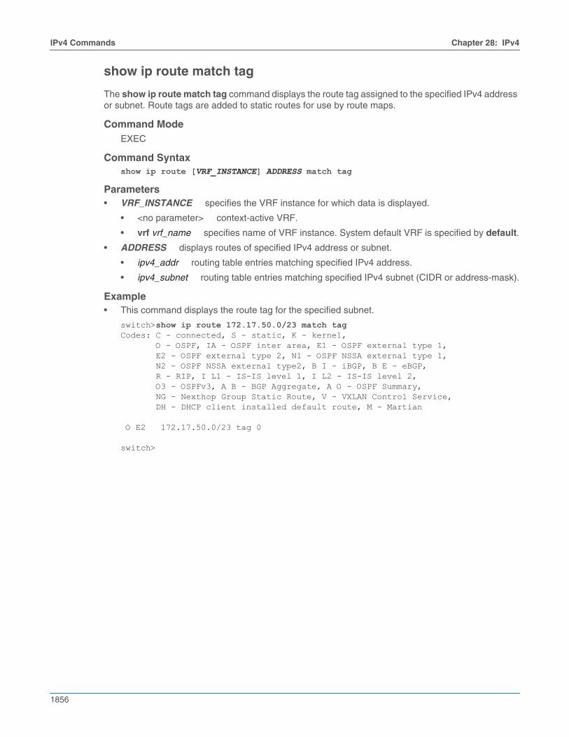
1856
IPv4 Commands Chapter 28: IPv4
show ip route match tag
The show ip route match tag command displays the route tag assigned to the specified IPv4 addressor subnet. Route tags are added to static routes for use by route maps.
Command ModeEXEC
Command Syntaxshow ip route [VRF_INSTANCE] ADDRESS match tag
Parameters• VRF_INSTANCE specifies the VRF instance for which data is displayed.
• <no parameter> context-active VRF.
• vrf vrf_name specifies name of VRF instance. System default VRF is specified by default.
• ADDRESS displays routes of specified IPv4 address or subnet.
• ipv4_addr routing table entries matching specified IPv4 address.
• ipv4_subnet routing table entries matching specified IPv4 subnet (CIDR or address-mask).
Example• This command displays the route tag for the specified subnet.
switch>show ip route 172.17.50.0/23 match tagCodes: C - connected, S - static, K - kernel, O - OSPF, IA - OSPF inter area, E1 - OSPF external type 1, E2 - OSPF external type 2, N1 - OSPF NSSA external type 1, N2 - OSPF NSSA external type2, B I - iBGP, B E - eBGP, R - RIP, I L1 - IS-IS level 1, I L2 - IS-IS level 2, O3 - OSPFv3, A B - BGP Aggregate, A O - OSPF Summary, NG - Nexthop Group Static Route, V - VXLAN Control Service, DH - DHCP client installed default route, M - Martian
O E2 172.17.50.0/23 tag 0
switch>
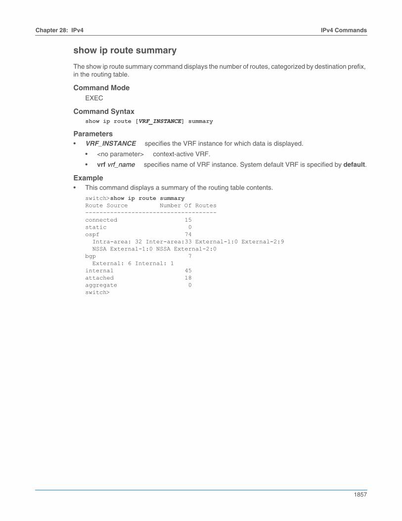
Chapter 28: IPv4 IPv4 Commands
1857
show ip route summary
The show ip route summary command displays the number of routes, categorized by destination prefix,in the routing table.
Command ModeEXEC
Command Syntaxshow ip route [VRF_INSTANCE] summary
Parameters• VRF_INSTANCE specifies the VRF instance for which data is displayed.
• <no parameter> context-active VRF.
• vrf vrf_name specifies name of VRF instance. System default VRF is specified by default.
Example• This command displays a summary of the routing table contents.
switch>show ip route summaryRoute Source Number Of Routes-------------------------------------connected 15static 0ospf 74 Intra-area: 32 Inter-area:33 External-1:0 External-2:9 NSSA External-1:0 NSSA External-2:0bgp 7 External: 6 Internal: 1internal 45attached 18aggregate 0switch>
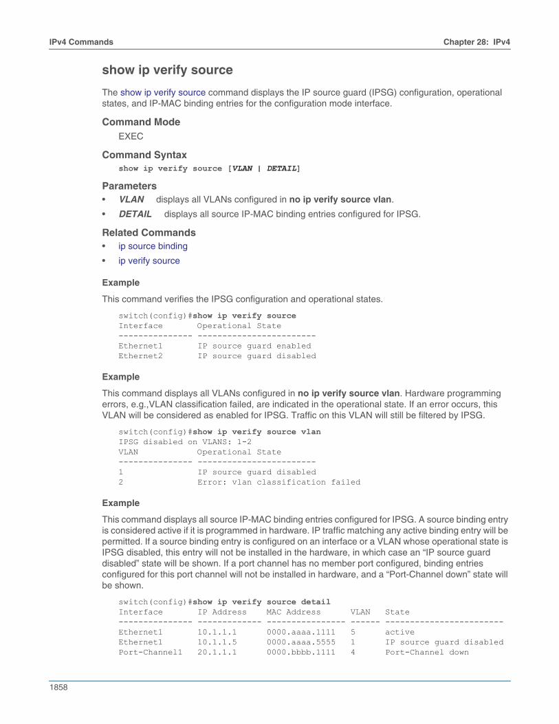
1858
IPv4 Commands Chapter 28: IPv4
show ip verify source
The show ip verify source command displays the IP source guard (IPSG) configuration, operationalstates, and IP-MAC binding entries for the configuration mode interface.
Command ModeEXEC
Command Syntaxshow ip verify source [VLAN | DETAIL]
Parameters• VLAN displays all VLANs configured in no ip verify source vlan.
• DETAIL displays all source IP-MAC binding entries configured for IPSG.
Related Commands• ip source binding
• ip verify source
Example
This command verifies the IPSG configuration and operational states.
switch(config)#show ip verify sourceInterface Operational State--------------- ------------------------Ethernet1 IP source guard enabledEthernet2 IP source guard disabled
Example
This command displays all VLANs configured in no ip verify source vlan. Hardware programmingerrors, e.g.,VLAN classification failed, are indicated in the operational state. If an error occurs, thisVLAN will be considered as enabled for IPSG. Traffic on this VLAN will still be filtered by IPSG.
switch(config)#show ip verify source vlanIPSG disabled on VLANS: 1-2VLAN Operational State--------------- ------------------------1 IP source guard disabled2 Error: vlan classification failed
Example
This command displays all source IP-MAC binding entries configured for IPSG. A source binding entryis considered active if it is programmed in hardware. IP traffic matching any active binding entry will bepermitted. If a source binding entry is configured on an interface or a VLAN whose operational state isIPSG disabled, this entry will not be installed in the hardware, in which case an “IP source guarddisabled” state will be shown. If a port channel has no member port configured, binding entriesconfigured for this port channel will not be installed in hardware, and a “Port-Channel down” state willbe shown.
switch(config)#show ip verify source detailInterface IP Address MAC Address VLAN State--------------- ------------- ---------------- ------ ------------------------Ethernet1 10.1.1.1 0000.aaaa.1111 5 activeEthernet1 10.1.1.5 0000.aaaa.5555 1 IP source guard disabledPort-Channel1 20.1.1.1 0000.bbbb.1111 4 Port-Channel down
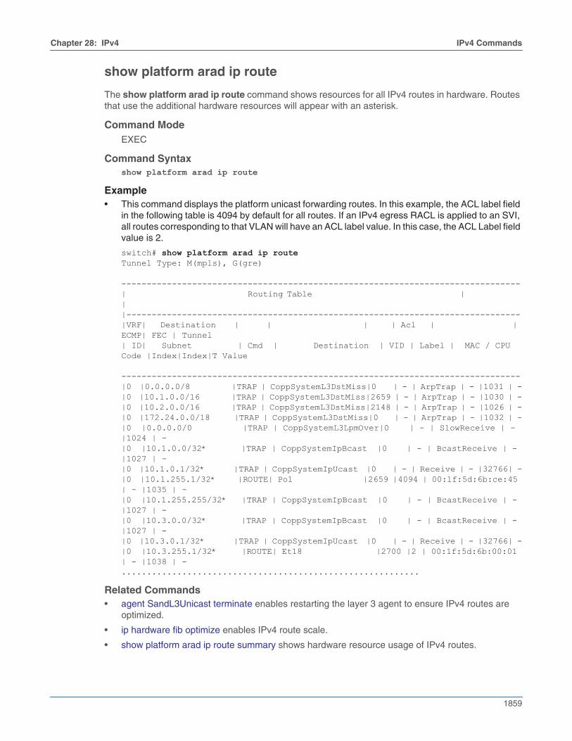
Chapter 28: IPv4 IPv4 Commands
1859
show platform arad ip route
The show platform arad ip route command shows resources for all IPv4 routes in hardware. Routesthat use the additional hardware resources will appear with an asterisk.
Command ModeEXEC
Command Syntaxshow platform arad ip route
Example• This command displays the platform unicast forwarding routes. In this example, the ACL label field
in the following table is 4094 by default for all routes. If an IPv4 egress RACL is applied to an SVI,all routes corresponding to that VLAN will have an ACL label value. In this case, the ACL Label fieldvalue is 2.
switch# show platform arad ip routeTunnel Type: M(mpls), G(gre) -------------------------------------------------------------------------------| Routing Table | ||------------------------------------------------------------------------------|VRF| Destination | | | | Acl | | ECMP| FEC | Tunnel| ID| Subnet | Cmd | Destination | VID | Label | MAC / CPU Code |Index|Index|T Value -------------------------------------------------------------------------------|0 |0.0.0.0/8 |TRAP | CoppSystemL3DstMiss|0 | - | ArpTrap | - |1031 | -|0 |10.1.0.0/16 |TRAP | CoppSystemL3DstMiss|2659 | - | ArpTrap | - |1030 | -|0 |10.2.0.0/16 |TRAP | CoppSystemL3DstMiss|2148 | - | ArpTrap | - |1026 | -|0 |172.24.0.0/18 |TRAP | CoppSystemL3DstMiss|0 | - | ArpTrap | - |1032 | -|0 |0.0.0.0/0 |TRAP | CoppSystemL3LpmOver|0 | - | SlowReceive | - |1024 | -|0 |10.1.0.0/32* |TRAP | CoppSystemIpBcast |0 | - | BcastReceive | - |1027 | -|0 |10.1.0.1/32* |TRAP | CoppSystemIpUcast |0 | - | Receive | - |32766| -|0 |10.1.255.1/32* |ROUTE| Po1 |2659 |4094 | 00:1f:5d:6b:ce:45 | - |1035 | -|0 |10.1.255.255/32* |TRAP | CoppSystemIpBcast |0 | - | BcastReceive | - |1027 | -|0 |10.3.0.0/32* |TRAP | CoppSystemIpBcast |0 | - | BcastReceive | - |1027 | -|0 |10.3.0.1/32* |TRAP | CoppSystemIpUcast |0 | - | Receive | - |32766| -|0 |10.3.255.1/32* |ROUTE| Et18 |2700 |2 | 00:1f:5d:6b:00:01 | - |1038 | -...........................................................
Related Commands• agent SandL3Unicast terminate enables restarting the layer 3 agent to ensure IPv4 routes are
optimized.
• ip hardware fib optimize enables IPv4 route scale.
• show platform arad ip route summary shows hardware resource usage of IPv4 routes.
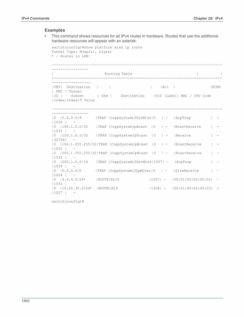
1860
IPv4 Commands Chapter 28: IPv4
Examples• This command shows resources for all IPv4 routes in hardware. Routes that use the additional
hardware resources will appear with an asterisk.
switch(config)#show platform arad ip routeTunnel Type: M(mpls), G(gre)* - Routes in LEM ------------------------------------------------------------------------------------------------| Routing Table | ||------------------------------------------------------------------------------------------------|VRF| Destination | | | |Acl | |ECMP | FEC | Tunnel|ID | Subnet | Cmd | Destination |VID |Label| MAC / CPU Code |Index|Index|T Value ------------------------------------------------------------------------------------------------|0 |0.0.0.0/8 |TRAP |CoppSystemL3DstMiss|0 | - |ArpTrap | - |1030 | - |0 |100.1.0.0/32 |TRAP |CoppSystemIpBcast |0 | - |BcastReceive | - |1032 | - |0 |100.1.0.0/32 |TRAP |CoppSystemIpUcast |0 | - |Receive | - |32766| - |0 |100.1.255.255/32|TRAP |CoppSystemIpBcast |0 | - |BcastReceive | - |1032 | - |0 |200.1.255.255/32|TRAP |CoppSystemIpBcast |0 | - |BcastReceive | - |1032 | - |0 |200.1.0.0/16 |TRAP |CoppSystemL3DstMiss|1007| - |ArpTrap | - |1029 | - |0 |0.0.0.0/0 |TRAP |CoppSystemL3LpmOver|0 | - |SlowReceive | - |1024 | - |0 |4.4.4.0/24* |ROUTE|Et10 |1007| - |00:01:00:02:00:03| - |1033 | - |0 |10.20.30.0/24* |ROUTE|Et9 |1006| - |00:01:00:02:00:03| - |1027 | -
switch(config)#

Chapter 28: IPv4 IPv4 Commands
1861
show platform arad ip route summary
The show platform arad ip route summary command shows hardware resource usage of IPv4routes.
Command ModeEXEC
Command Syntaxshow platform arad ip route summary
Related Commands• agent SandL3Unicast terminate enables restarting the layer 3 agent to ensure IPv4 routes are
optimized.
• ip hardware fib optimize enables IPv4 route scale.
• show platform arad ip route shows resources for all IPv4 routes in hardware. Routes that use theadditional hardware resources will appear with an asterisk.
Example• This command shows hardware resource usage of IPv4 routes.
switch(config)#show platform arad ip route summaryTotal number of VRFs: 1Total number of routes: 25Total number of route-paths: 21Total number of lem-routes: 4
switch(config)#
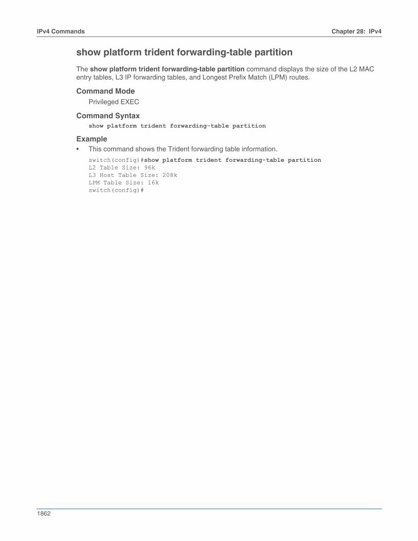
1862
IPv4 Commands Chapter 28: IPv4
show platform trident forwarding-table partition
The show platform trident forwarding-table partition command displays the size of the L2 MACentry tables, L3 IP forwarding tables, and Longest Prefix Match (LPM) routes.
Command ModePrivileged EXEC
Command Syntaxshow platform trident forwarding-table partition
Example• This command shows the Trident forwarding table information.
switch(config)#show platform trident forwarding-table partitionL2 Table Size: 96kL3 Host Table Size: 208kLPM Table Size: 16kswitch(config)#
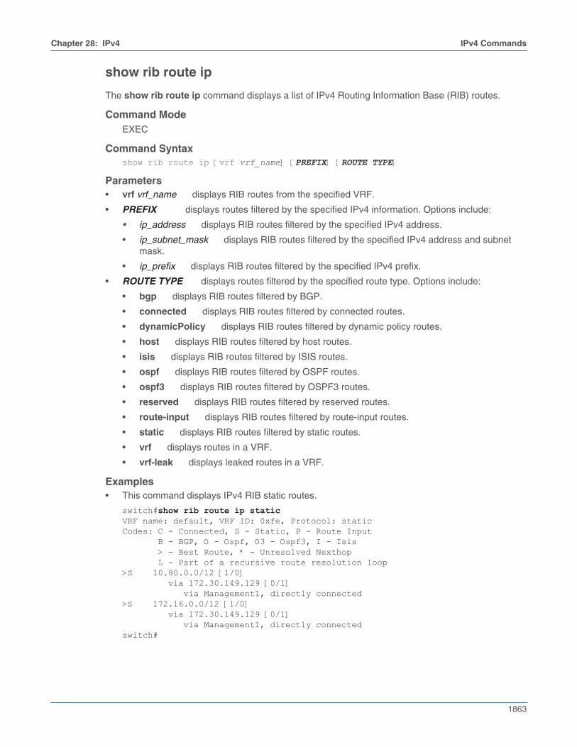
Chapter 28: IPv4 IPv4 Commands
1863
show rib route ip
The show rib route ip command displays a list of IPv4 Routing Information Base (RIB) routes.
Command ModeEXEC
Command Syntaxshow rib route ip [vrf vrf_name] [PREFIX] [ROUTE TYPE]
Parameters• vrf vrf_name displays RIB routes from the specified VRF.
• PREFIX displays routes filtered by the specified IPv4 information. Options include:
• ip_address displays RIB routes filtered by the specified IPv4 address.
• ip_subnet_mask displays RIB routes filtered by the specified IPv4 address and subnetmask.
• ip_prefix displays RIB routes filtered by the specified IPv4 prefix.
• ROUTE TYPE displays routes filtered by the specified route type. Options include:
• bgp displays RIB routes filtered by BGP.
• connected displays RIB routes filtered by connected routes.
• dynamicPolicy displays RIB routes filtered by dynamic policy routes.
• host displays RIB routes filtered by host routes.
• isis displays RIB routes filtered by ISIS routes.
• ospf displays RIB routes filtered by OSPF routes.
• ospf3 displays RIB routes filtered by OSPF3 routes.
• reserved displays RIB routes filtered by reserved routes.
• route-input displays RIB routes filtered by route-input routes.
• static displays RIB routes filtered by static routes.
• vrf displays routes in a VRF.
• vrf-leak displays leaked routes in a VRF.
Examples• This command displays IPv4 RIB static routes.
switch#show rib route ip staticVRF name: default, VRF ID: 0xfe, Protocol: staticCodes: C - Connected, S - Static, P - Route Input B - BGP, O - Ospf, O3 - Ospf3, I - Isis > - Best Route, * - Unresolved Nexthop L - Part of a recursive route resolution loop>S 10.80.0.0/12 [1/0] via 172.30.149.129 [0/1] via Management1, directly connected>S 172.16.0.0/12 [1/0] via 172.30.149.129 [0/1] via Management1, directly connectedswitch#
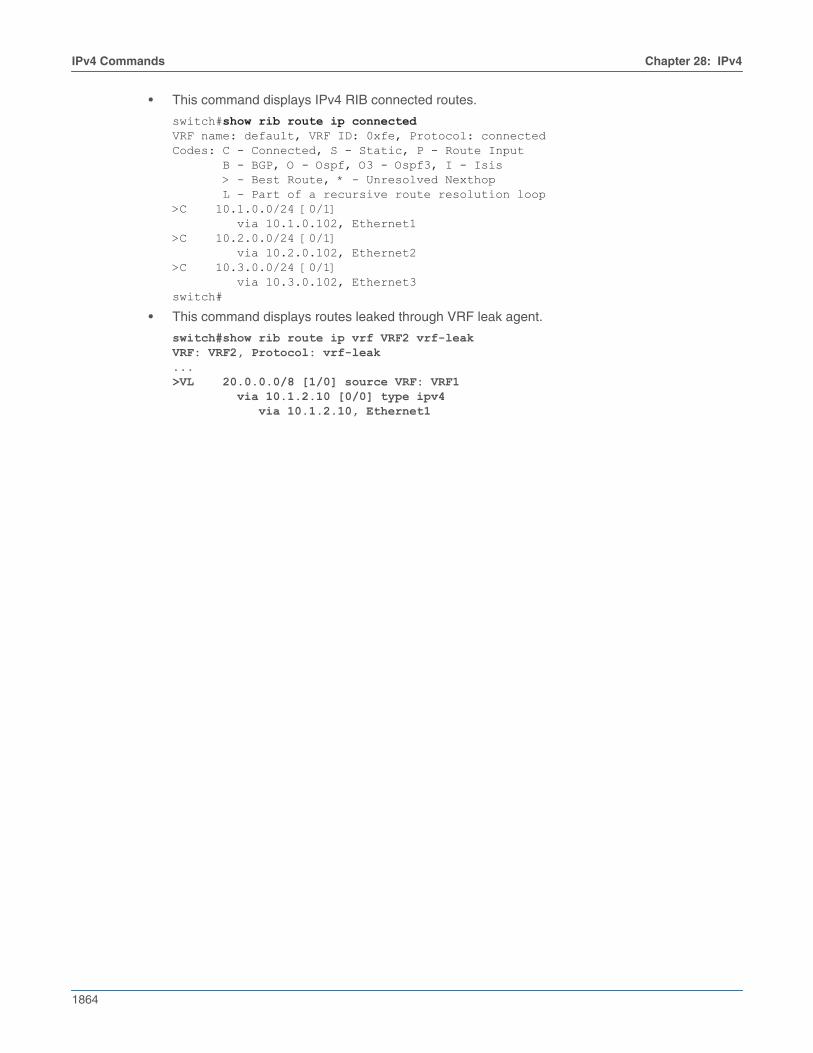
1864
IPv4 Commands Chapter 28: IPv4
• This command displays IPv4 RIB connected routes.
switch#show rib route ip connectedVRF name: default, VRF ID: 0xfe, Protocol: connectedCodes: C - Connected, S - Static, P - Route Input B - BGP, O - Ospf, O3 - Ospf3, I - Isis > - Best Route, * - Unresolved Nexthop L - Part of a recursive route resolution loop>C 10.1.0.0/24 [0/1] via 10.1.0.102, Ethernet1>C 10.2.0.0/24 [0/1] via 10.2.0.102, Ethernet2>C 10.3.0.0/24 [0/1] via 10.3.0.102, Ethernet3switch#
• This command displays routes leaked through VRF leak agent.
switch#show rib route ip vrf VRF2 vrf-leakVRF: VRF2, Protocol: vrf-leak...>VL 20.0.0.0/8 [1/0] source VRF: VRF1 via 10.1.2.10 [0/0] type ipv4 via 10.1.2.10, Ethernet1
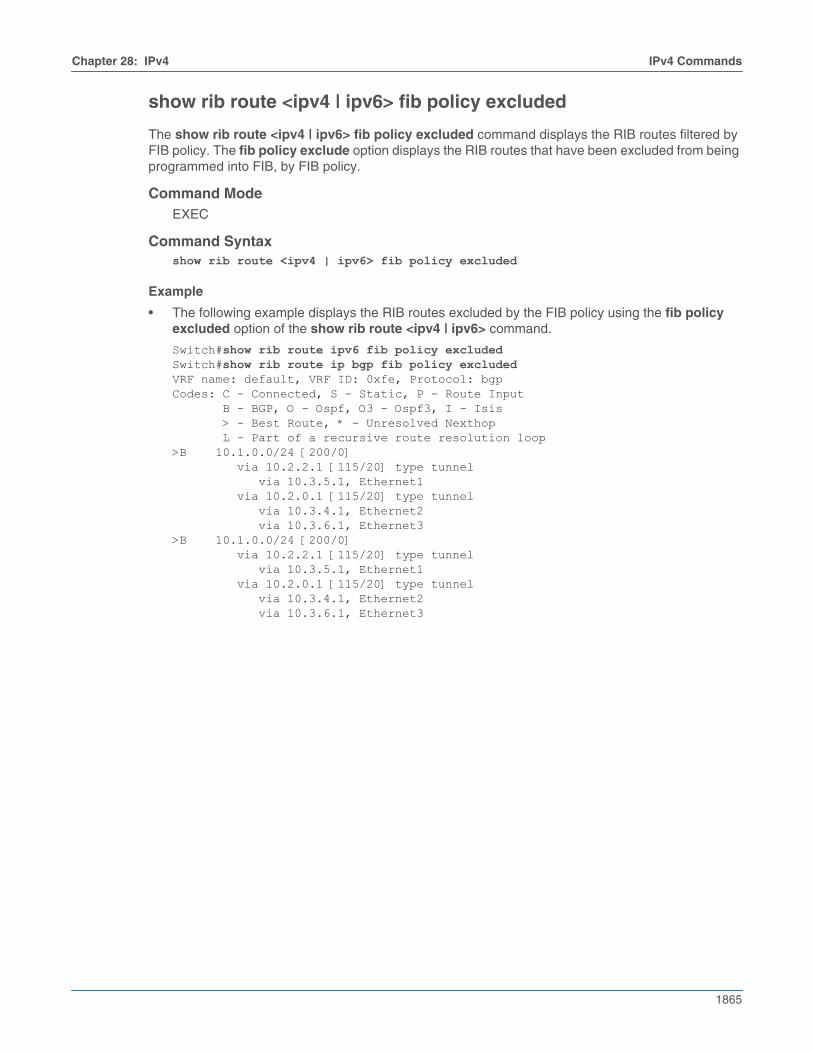
Chapter 28: IPv4 IPv4 Commands
1865
show rib route <ipv4 | ipv6> fib policy excluded
The show rib route <ipv4 | ipv6> fib policy excluded command displays the RIB routes filtered byFIB policy. The fib policy exclude option displays the RIB routes that have been excluded from beingprogrammed into FIB, by FIB policy.
Command ModeEXEC
Command Syntaxshow rib route <ipv4 | ipv6> fib policy excluded
Example
• The following example displays the RIB routes excluded by the FIB policy using the fib policyexcluded option of the show rib route <ipv4 | ipv6> command.
Switch#show rib route ipv6 fib policy excludedSwitch#show rib route ip bgp fib policy excludedVRF name: default, VRF ID: 0xfe, Protocol: bgpCodes: C - Connected, S - Static, P - Route Input B - BGP, O - Ospf, O3 - Ospf3, I - Isis > - Best Route, * - Unresolved Nexthop L - Part of a recursive route resolution loop>B 10.1.0.0/24 [200/0] via 10.2.2.1 [115/20] type tunnel via 10.3.5.1, Ethernet1 via 10.2.0.1 [115/20] type tunnel via 10.3.4.1, Ethernet2 via 10.3.6.1, Ethernet3 >B 10.1.0.0/24 [200/0] via 10.2.2.1 [115/20] type tunnel via 10.3.5.1, Ethernet1 via 10.2.0.1 [115/20] type tunnel via 10.3.4.1, Ethernet2 via 10.3.6.1, Ethernet3
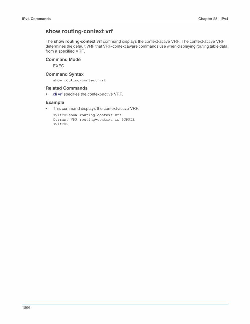
1866
IPv4 Commands Chapter 28: IPv4
show routing-context vrf
The show routing-context vrf command displays the context-active VRF. The context-active VRFdetermines the default VRF that VRF-context aware commands use when displaying routing table datafrom a specified VRF.
Command ModeEXEC
Command Syntaxshow routing-context vrf
Related Commands• cli vrf specifies the context-active VRF.
Example• This command displays the context-active VRF.
switch>show routing-context vrfCurrent VRF routing-context is PURPLEswitch>
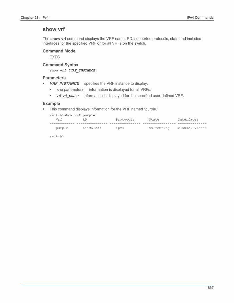
Chapter 28: IPv4 IPv4 Commands
1867
show vrf
The show vrf command displays the VRF name, RD, supported protocols, state and includedinterfaces for the specified VRF or for all VRFs on the switch.
Command ModeEXEC
Command Syntaxshow vrf [VRF_INSTANCE]
Parameters• VRF_INSTANCE specifies the VRF instance to display.
• <no parameter> information is displayed for all VRFs.
• vrf vrf_name information is displayed for the specified user-defined VRF.
Example• This command displays information for the VRF named “purple.”
switch>show vrf purple Vrf RD Protocols State Interfaces------------ --------------- --------------- ---------------- -------------- purple 64496:237 ipv4 no routing Vlan42, Vlan43
switch>
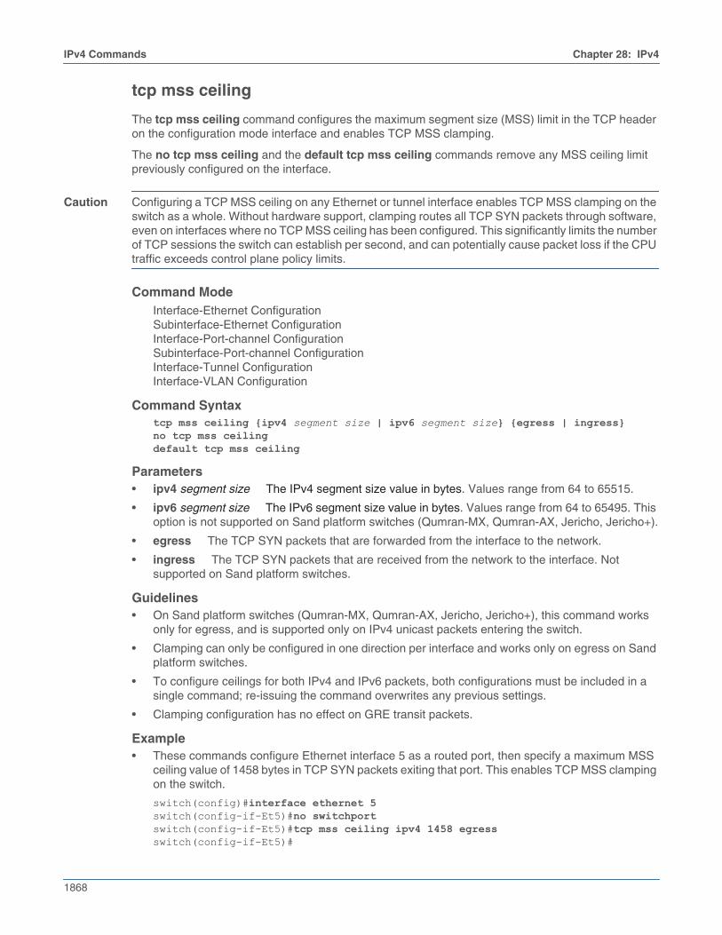
1868
IPv4 Commands Chapter 28: IPv4
tcp mss ceiling
The tcp mss ceiling command configures the maximum segment size (MSS) limit in the TCP headeron the configuration mode interface and enables TCP MSS clamping.
The no tcp mss ceiling and the default tcp mss ceiling commands remove any MSS ceiling limitpreviously configured on the interface.
Caution Configuring a TCP MSS ceiling on any Ethernet or tunnel interface enables TCP MSS clamping on theswitch as a whole. Without hardware support, clamping routes all TCP SYN packets through software,even on interfaces where no TCP MSS ceiling has been configured. This significantly limits the numberof TCP sessions the switch can establish per second, and can potentially cause packet loss if the CPUtraffic exceeds control plane policy limits.
Command ModeInterface-Ethernet ConfigurationSubinterface-Ethernet ConfigurationInterface-Port-channel ConfigurationSubinterface-Port-channel ConfigurationInterface-Tunnel ConfigurationInterface-VLAN Configuration
Command Syntaxtcp mss ceiling {ipv4 segment size | ipv6 segment size} {egress | ingress}no tcp mss ceilingdefault tcp mss ceiling
Parameters• ipv4 segment size The IPv4 segment size value in bytes. Values range from 64 to 65515.
• ipv6 segment size The IPv6 segment size value in bytes. Values range from 64 to 65495. Thisoption is not supported on Sand platform switches (Qumran-MX, Qumran-AX, Jericho, Jericho+).
• egress The TCP SYN packets that are forwarded from the interface to the network.
• ingress The TCP SYN packets that are received from the network to the interface. Notsupported on Sand platform switches.
Guidelines• On Sand platform switches (Qumran-MX, Qumran-AX, Jericho, Jericho+), this command works
only for egress, and is supported only on IPv4 unicast packets entering the switch.
• Clamping can only be configured in one direction per interface and works only on egress on Sandplatform switches.
• To configure ceilings for both IPv4 and IPv6 packets, both configurations must be included in asingle command; re-issuing the command overwrites any previous settings.
• Clamping configuration has no effect on GRE transit packets.
Example• These commands configure Ethernet interface 5 as a routed port, then specify a maximum MSS
ceiling value of 1458 bytes in TCP SYN packets exiting that port. This enables TCP MSS clampingon the switch.
switch(config)#interface ethernet 5switch(config-if-Et5)#no switchportswitch(config-if-Et5)#tcp mss ceiling ipv4 1458 egressswitch(config-if-Et5)#
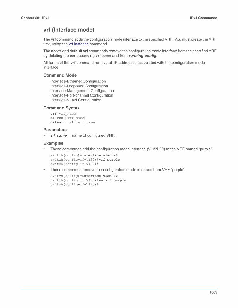
Chapter 28: IPv4 IPv4 Commands
1869
vrf (Interface mode)
The vrf command adds the configuration mode interface to the specified VRF. You must create the VRFfirst, using the vrf instance command.
The no vrf and default vrf commands remove the configuration mode interface from the specified VRFby deleting the corresponding vrf command from running-config.
All forms of the vrf command remove all IP addresses associated with the configuration modeinterface.
Command ModeInterface-Ethernet ConfigurationInterface-Loopback ConfigurationInterface-Management ConfigurationInterface-Port-channel ConfigurationInterface-VLAN Configuration
Command Syntaxvrf vrf_nameno vrf [vrf_name]default vrf [vrf_name]
Parameters• vrf_name name of configured VRF.
Examples• These commands add the configuration mode interface (VLAN 20) to the VRF named “purple”.
switch(config)#interface vlan 20switch(config-if-Vl20)#vrf purpleswitch(config-if-Vl20)#
• These commands remove the configuration mode interface from VRF “purple”.
switch(config)#interface vlan 20switch(config-if-Vl20)#no vrf purpleswitch(config-if-Vl20)#

1870
IPv4 Commands Chapter 28: IPv4
vrf instance
The vrf instance command places the switch in VRF configuration mode for the specified VRF. If thenamed VRF does not exist, this command creates it. The number of user-defined VRFs supportedvaries by platform.
To add an interface to the VRF once it is created, use the vrf (Interface mode) command.
The no vrf instance and default vrf instance commands delete the specified VRF instance byremoving the corresponding vrf instance command from running-config. This also removes all IPaddresses associated with interfaces that belong to the deleted VRF.
The exit command returns the switch to global configuration mode.
Command ModeGlobal Configuration
Command Syntaxvrf instance vrf_nameno vrf instance vrf_namedefault vrf instance vrf_name
Parameters• vrf_name Name of VRF being created, deleted or configured. The names “main” and “default”
are reserved.
Example• This command creates a VRF named “purple” and places the switch in VRF configuration mode
for that VRF.
switch(config)#vrf instance purpleswitch(config-vrf-purple)#
Chapter 28: IPv4 IPv4 Commands
1871
interface tunnel
The interface tunnel command places the switch in interface-tunnel configuration mode.
Interface-tunnel configuration mode is not a group change mode; running-config is changedimmediately after commands are executed.
The no interface tunnel command deletes the specified interface tunnel configuration.
The exit command returns the switch to the global configuration mode.
Command ModeGlobal Configuration
Command Syntaxinterface tunnel <number>no interface tunnel <number>
Parameter• number Tunnel interface number. Values range from 0 to 255.
Example• This command places the switch in interface-tunnel configuration mode for tunnel interface 10.
switch(config)#interface tunnel 10switch(config-if-Tu10)#

1872
IPv4 Commands Chapter 28: IPv4
tunnel
The tunnel command configures options for protocol-over-protocol tunneling. Becauseinterface-tunnel configuration mode is not a group change mode, running-config is changedimmediately after commands are executed. The exit command does not affect the configuration.
The no tunnel command deletes the specified tunnel configuration.
Command ModeInterface-tunnel Configuration
Command Syntaxtunnel <options>no tunnel <options>
Parameters• options Specifies the various tunneling options as listed below.
• destination destination address of the tunnel.
• ipsec secures the tunnel with the IPsec address.
• key sets the tunnel key.
• mode tunnel encapsulation method.
• path-mtu-discovery enables the Path MTU discovery on tunnel.
• source source of the tunnel packets.
• tos sets the IP type of service value.
• ttl sets time to live value.
• underlay tunnel underlay.
Example• These commands place the switch in interface-tunnel configuration mode for tunnel interface 10
and with GRE tunnel configured on the interfaces specified.
switch(config)#ip routingswitch(config)#interface Tunnel 10switch(config-if-Tu10)#tunnel mode greswitch(config-if-Tu10)#ip address 192.168.1.1/24switch(config-if-Tu10)#tunnel source 10.1.1.1switch(config-if-Tu10)#tunnel destination 10.1.1.2switch(config-if-Tu10)#tunnel path-mtu-discoveryswitch(config-if-Tu10)#tunnel tos 10switch(config-if-Tu10)#tunnel ttl 10
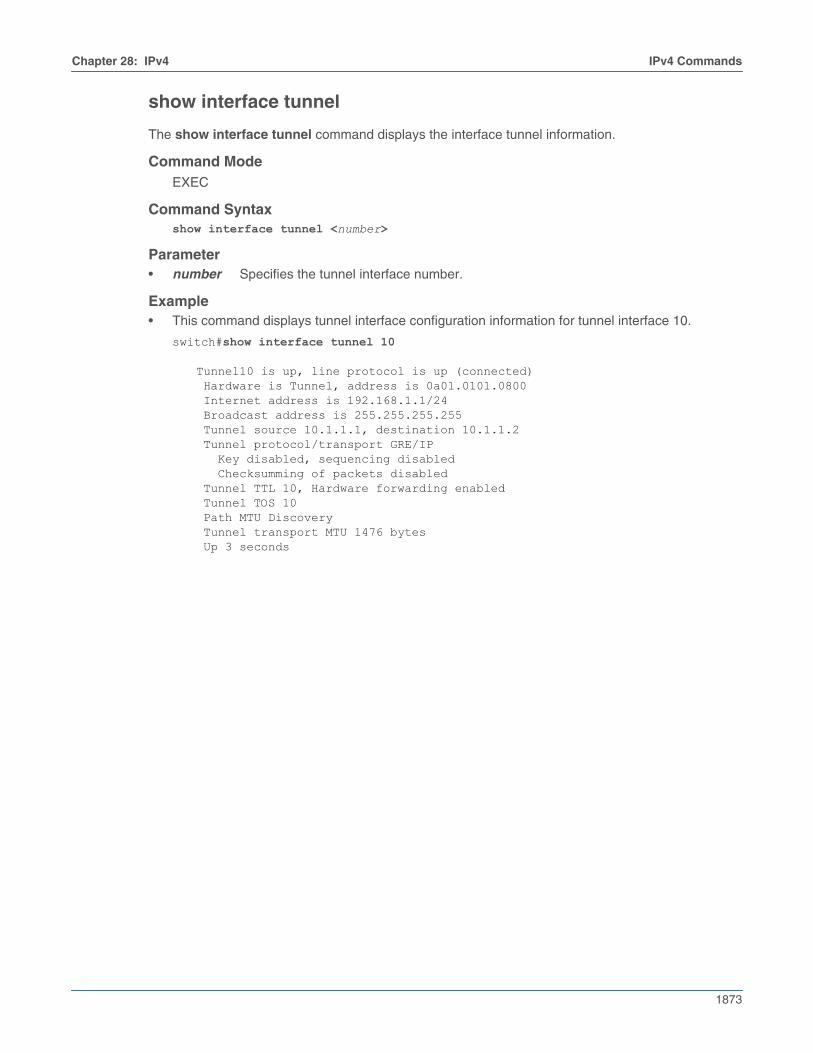
Chapter 28: IPv4 IPv4 Commands
1873
show interface tunnel
The show interface tunnel command displays the interface tunnel information.
Command ModeEXEC
Command Syntaxshow interface tunnel <number>
Parameter• number Specifies the tunnel interface number.
Example• This command displays tunnel interface configuration information for tunnel interface 10.
switch#show interface tunnel 10
Tunnel10 is up, line protocol is up (connected) Hardware is Tunnel, address is 0a01.0101.0800 Internet address is 192.168.1.1/24 Broadcast address is 255.255.255.255 Tunnel source 10.1.1.1, destination 10.1.1.2 Tunnel protocol/transport GRE/IP Key disabled, sequencing disabled Checksumming of packets disabled Tunnel TTL 10, Hardware forwarding enabled Tunnel TOS 10 Path MTU Discovery Tunnel transport MTU 1476 bytes Up 3 seconds
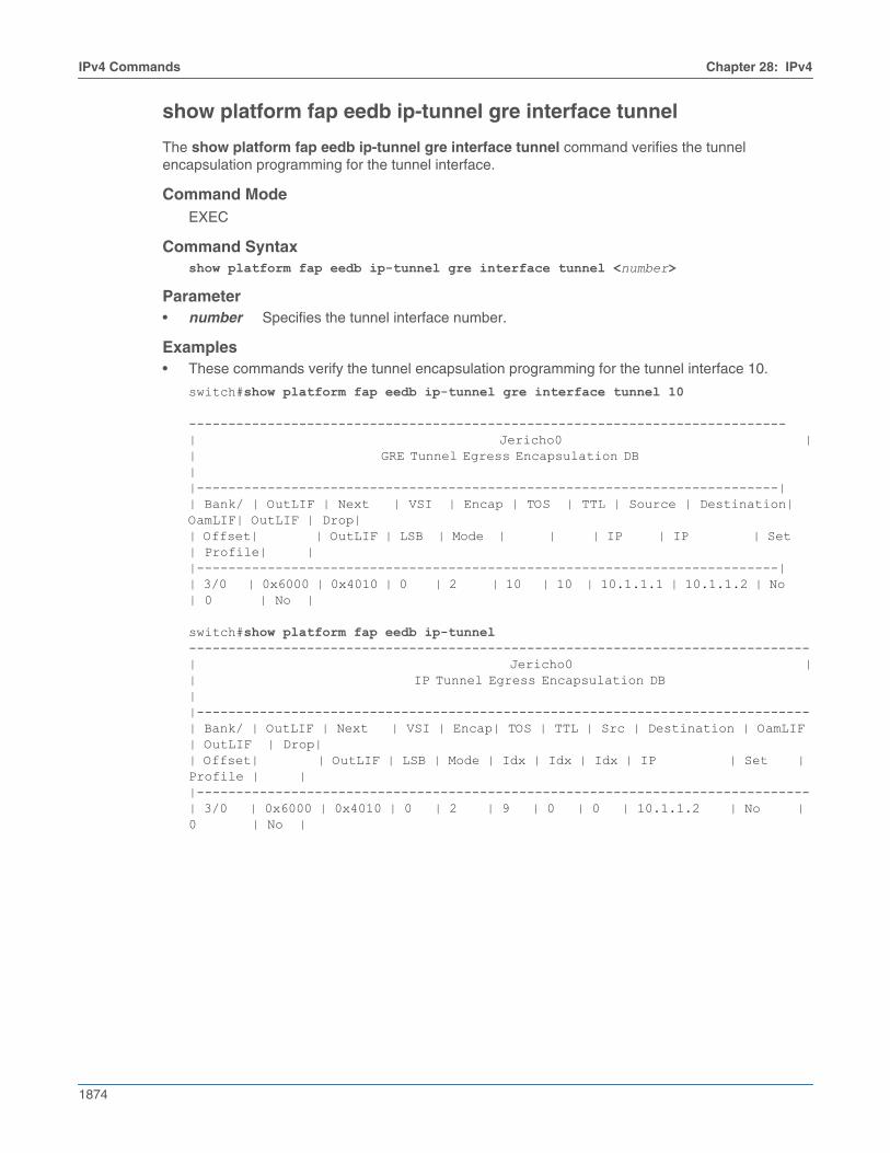
1874
IPv4 Commands Chapter 28: IPv4
show platform fap eedb ip-tunnel gre interface tunnel
The show platform fap eedb ip-tunnel gre interface tunnel command verifies the tunnelencapsulation programming for the tunnel interface.
Command ModeEXEC
Command Syntaxshow platform fap eedb ip-tunnel gre interface tunnel <number>
Parameter• number Specifies the tunnel interface number.
Examples• These commands verify the tunnel encapsulation programming for the tunnel interface 10.
switch#show platform fap eedb ip-tunnel gre interface tunnel 10
----------------------------------------------------------------------------| Jericho0 || GRE Tunnel Egress Encapsulation DB ||--------------------------------------------------------------------------|| Bank/ | OutLIF | Next | VSI | Encap | TOS | TTL | Source | Destination| OamLIF| OutLIF | Drop|| Offset| | OutLIF | LSB | Mode | | | IP | IP | Set | Profile| ||--------------------------------------------------------------------------|| 3/0 | 0x6000 | 0x4010 | 0 | 2 | 10 | 10 | 10.1.1.1 | 10.1.1.2 | No | 0 | No |
switch#show platform fap eedb ip-tunnel-------------------------------------------------------------------------------| Jericho0 || IP Tunnel Egress Encapsulation DB ||------------------------------------------------------------------------------| Bank/ | OutLIF | Next | VSI | Encap| TOS | TTL | Src | Destination | OamLIF | OutLIF | Drop|| Offset| | OutLIF | LSB | Mode | Idx | Idx | Idx | IP | Set | Profile | ||------------------------------------------------------------------------------| 3/0 | 0x6000 | 0x4010 | 0 | 2 | 9 | 0 | 0 | 10.1.1.2 | No | 0 | No |
Chapter 28: IPv4 IPv4 Commands
1875
show tunnel fib static interface gre
The show tunnel fib static interface gre command displays the forwarding information base (FIB)information for a static interface GRE tunnel.
Command ModeEXEC
Command Syntaxshow tunnel fib static interface gre <number>
Parameter• number Specifies the tunnel index number.
Example• This command display the interface tunnel configuration with GRE configured.
switch#show tunnel fib static interface gre 10
Type 'Static Interface', index 10, forwarding Primary via 10.6.1.2, 'Ethernet6/1' GRE, destination 10.1.1.2, source 10.1.1.1, ttl 10, tos 0xa

1876
IPv4 Commands Chapter 28: IPv4
show platform fap tcam summary
The show platform fap tcam summary command displays information about the TCAM bank that isallocated for GRE packet termination lookup.
Command ModeEXEC
Command Syntaxshow platform fap tcam summary
Example• This command verifies if the TCAM bank is allocated for GRE packet termination lookup.
switch#show platform fap tcam summary
Tcam Allocation (Jericho0) Bank Used By Reserved By---------- ------------------------- ----------- 0 dbGreTunnel -