chapter 27 bearings - wisconsindot.gov · wisdot bridge manual chapter 27 – bearings january 2017...
TRANSCRIPT
WisDOT Bridge Manual Chapter 27 – Bearings
January 2017 27-1
Table of Contents
27.1 General ............................................................................................................................ 2
27.2 Bearing Types .................................................................................................................. 3
27.2.1 Elastomeric Bearings ................................................................................................ 4
27.2.2 Steel Bearings ........................................................................................................ 11
27.2.2.1 Type "A" Fixed Bearings ................................................................................. 11
27.2.2.2 Type "A-T" Expansion Bearings ...................................................................... 12
27.2.2.3 High-Load Multi-Rotational Bearings ............................................................... 12
27.3 Hold Down Devices ........................................................................................................ 18
27.4 Design Example ............................................................................................................. 19
WisDOT Bridge Manual Chapter 27 – Bearings
January 2017 27-2
27.1 General
Bridges supported in the conventional way by abutments and piers require bearings to transfer girder reactions without overstressing the supports, ensuring that the bridge functions as intended. Bridges usually require bearings that are more elaborate than those required for building columns, girders and trusses. Bridge bearings require greater consideration in minimizing forces caused by temperature change, friction and restraint against elastic deformations. A more detailed analysis in bridge bearing design considers the following:
• Bridges are usually supported by reinforced concrete substructure units, and the magnitude of the horizontal thrust determines the size of the substructure units. The coefficient of friction on bridge bearings should be as low as possible.
• Bridge bearings must be capable of withstanding and transferring dynamic forces and the resulting vibrations without causing eventual wear and destruction of the substructure units.
• Most bridges are exposed to the elements of nature. Bridge bearings are subjected to more frequent and greater total expansion and contraction movement due to changes in temperature than those required by buildings. Since bridge bearings are exposed to the weather, they are designed as maintenance-free as possible.
WisDOT policy item:
The temperature range considered for steel girder superstructures is -30°F to 120°F. A temperature setting table for steel bearings is used for steel girders; where 45°F is the neutral temperature, resulting in a range of 120° - 45° = 75° for bearing design.
The temperature range considered for prestressed concrete girder superstructures is 5°F to 85°F. Using an installation temperature of 60° for prestressed girders, the resulting range is 60° - 5° = 55° for bearing design. For prestressed girders an additional shrinkage factor of 0.0003 ft/ft shall also be accounted for. No temperature setting table is used for prestressed concrete girders.
See the Standard for Steel Expansion Bearing Details to determine bearing plate “A” sizing (steel girders) or anchor plate sizing (prestressed concrete girders). This standard also gives an example of a temperature setting table for steel bearings when used for steel girders.
WisDOT policy item:
According to LRFD [14.4.1], the influence of dynamic load allowance need not be included for bearings. However, dynamic load allowance shall be included when designing bearings for bridges in Wisconsin. Apply dynamic load allowance in LRFD [3.6.2] to HL-93 live loads as stated in LRFD [3.6.1.2, 3.6.1.3] and distribute these loads, along with dead loads, to the bearings.
WisDOT Bridge Manual Chapter 27 – Bearings
January 2017 27-3
27.2 Bearing Types
Bridge bearings are of two general types: expansion and fixed. Bearings can be fixed in both the longitudinal and transverse directions, fixed in one direction and expansion in the other, or expansion in both directions. Expansion bearings provide for rotational movements of the girders, as well as longitudinal movement for the expansion and contraction of the bridge spans. If an expansion bearing develops a large resistance to longitudinal movement due to corrosion or other causes, this frictional force opposes the natural expansion or contraction of the span, creating a force within the span that could lead to a maintenance problem in the future. Fixed bearings act as hinges by permitting rotational movement, while at the same time preventing longitudinal movement. The function of the fixed bearing is to prevent the superstructure from moving longitudinally off of the substructure units. Both expansion and fixed bearings transfer lateral forces, as described in LRFD [Section 3], from the superstructure to the substructure units. Both bearing types are set parallel to the direction of structural movement; bearings are not set parallel to flared girders.
When deciding which bearings will be fixed and which will be expansion on a bridge, several guidelines are commonly considered:
• The bearing layout for a bridge must be developed as a consistent system. Vertical movements are resisted by all bearings, longitudinal horizontal movements are resisted by fixed bearings and facilitated in expansion bearings, and rotations are generally allowed to occur as freely as possible.
• For maintenance purposes, it is generally desirable to minimize the number of deck joints on a bridge, which can in turn affect the bearing layout.
• The bearing layout must facilitate the anticipated thermal movements, primarily in the longitudinal direction, but also in the transverse direction for wide bridges.
• It is generally desirable for the superstructure to expand in the uphill direction, wherever possible.
• If more than one substructure unit is fixed within a single superstructure unit, then forces will be induced into the fixed substructure units and must be considered during design. If only one pier is fixed, unbalanced friction forces from expansion bearings will induce force into the fixed pier.
• For curved bridges, the bearing layout can induce additional stresses into the superstructure, which must be considered during design.
• Forces are distributed to the bearings based on the superstructure analysis.
A valuable tool for selecting bearing types is presented in LRFD [Table 14.6.2-1], in which the suitability of various bearing types is presented in terms of movement, rotation and resistance to loads. In general, it is best to use a fixed or semi-expansion bearing utilizing an unreinforced elastomeric bearing pad whenever possible, provided adverse effects such as excessive force transfer to the substructure does not occur. Where a fixed bearing is required with greater rotational capacity, steel fixed bearings can be utilized. Laminated elastomeric bearings are

WisDOT Bridge Manual Chapter 27 – Bearings
January 2017 27-4
the preferred choice for expansion bearings. When such expansion bearings fail to meet project requirements, steel Type “A-T” expansion bearings should be used. For curved and/or highly skewed bridges, consideration should be given to the use of pot bearings.
27.2.1 Elastomeric Bearings
Elastomeric bearings are commonly used on small to moderate sized bridges. Elastomeric bearings are either fabricated as plain bearing pads (consisting of elastomer only) or as laminated (steel reinforced) bearings (consisting of alternate layers of steel reinforcement and elastomer bonded together during vulcanization). A sample plain elastomeric bearing pad is illustrated in Figure 27.2-1, and a sample laminated (steel reinforced) elastomeric bearing is illustrated in Figure 27.2-2.
These bearings are designed to transmit loads and accommodate movements between a bridge and its supporting structure. Plain elastomeric bearing pads can be used for small bridges, in which the vertical loads, translations and rotations are relatively small. Laminated (steel reinforced) elastomeric bearing pads are often used for larger bridges with more sizable vertical loads, translations and rotations. Performance information indicates that elastomeric bearings are functional and reliable when designed within the structural limits of the material. See LRFD [Section 14], AASHTO LRFD Bridge Construction Specifications, Section 18, and AASHTO M251 for design and construction requirements of elastomeric bearings.
WisDOT policy item:
WisDOT currently uses plain or laminated (steel reinforced) elastomeric bearings which are rectangular in shape. No other shapes or configurations are used for elastomeric bearings in Wisconsin.
Figure 27.2-1 Plain Elastomeric Bearing

WisDOT Bridge Manual Chapter 27 – Bearings
January 2017 27-5
Figure 27.2-2 Laminated (Steel Reinforced) Elastomeric Bearing
AASHTO LRFD does not permit tapered elastomer layers in reinforced bearings. Laminated (steel reinforced) bearings must be placed on a level surface; otherwise gravity loads will produce shear strain in the bearing due to inclined forces. The angle between the alignment of the underside of the girder (due to the slope of the grade line, camber and dead load rotation) and a horizontal line must not exceed 0.01 radians, as per LRFD [14.8.2]. If the angle is greater than 0.01 radians or if the rotation multiplied by the top plate length is 1/8” or more, the 1 1/2" top steel plate must be tapered to provide a level load surface along the bottom of this plate under these conditions. The tapered plate will have a minimum thickness of 1 1/2" per AASHTO Construction Specifications, Section 18.
Plain and laminated (steel reinforced) elastomeric bearings can be designed by Method A as outlined in LRFD [14.7.6] and NCHRP-248 or by Method B as shown in LRFD [14.7.5] and NCHRP-298.
WisDOT policy item:
WisDOT uses Method A, as described in LRFD [14.7.6], for elastomeric bearing design.
Method A results in a bearing with a lower capacity than a bearing designed using Method B. However, the increased capacity resulting from the use of Method B requires additional testing and quality control, and WisDOT currently does not have a system in place to verify these requirements.
For several years, plain elastomeric bearing pads have performed well on prestressed concrete girder structures. Refer to the Standard for Bearing Pad Details for Prestressed Concrete Girders for details. Prestressed concrete girders using this detail are fixed into the concrete diaphragms at the supports, and the girders are set on 1/2" thick plain elastomeric bearing pads. Laminated (steel reinforced) bearing details and steel plate and elastomer thicknesses are given on the Standard for Elastomeric Bearings for Prestressed Concrete Girders.
The design of an elastomeric bearing generally involves the following steps:
1. Obtain required design input LRFD [14.4 & 14.6]
Rubber Cover
Rubber Interior Layer Reinforcement
WisDOT Bridge Manual Chapter 27 – Bearings
January 2017 27-6
The required design input for the design of an elastomeric bearing at the service limit state is dead load, live load plus dynamic load allowance, minimum vertical force due to permanent load, and design translation. The required design input at the strength limit state is shear force. Other required design input is expansion length, girder or beam bottom flange width, minimum grade of elastomer, and temperature zone. Two temperature zones are shown for Wisconsin in LRFD [Figure 14.7.5.2-1], zones C and D. WisDOT policy is for all elastomeric bearings to meet Zone D requirements.
2. Select a feasible bearing type – plain or laminated (steel reinforced)
3. Select preliminary bearing properties LRFD [14.7.6.2]
The preliminary bearing properties can be obtained from LRFD [14.7.6.2] or from past experience. The preliminary bearing properties include elastomer cover thickness, elastomer internal layer thickness, elastomer hardness, elastomer shear modulus, elastomer creep deflection, pad length, pad width, number of steel reinforcement layers, steel reinforcement thickness, steel reinforcement yield strength and steel reinforcement constant-amplitude fatigue threshold. WisDOT uses the following properties:
• Elastomer cover thickness = 1/4"
• Elastomer internal layer thickness = 1/2"
• Elastomer hardness: Durometer 60 +/- 5
• Elastomer shear modulus (G): 0.1125 ksi < G < 0.165 ksi
• Elastomer creep deflection @ 25 years divided by instantaneous deflection = 0.30
• Steel reinforcement thickness = 1/8"
• Steel reinforcement yield strength = 36 ksi or 50 ksi
• Steel reinforcement constant-amplitude fatigue threshold = 24 ksi
However, not all of these properties are needed for a plain elastomeric bearing design.
4. Check shear deformation LRFD [14.7.6.3.4]
Shear deformation, ∆S, is the sum of deformation from thermal effects, ∆ST, as well as creep and shrinkage effects, ∆Scr/sh (∆S = ∆ST + ∆Scr/sh).
( )( )( )α∆=∆ TST lengthExpansion
Where:
∆T = Change in temperature (see 27.1) (degrees)

WisDOT Bridge Manual Chapter 27 – Bearings
January 2017 27-7
α = Coefficient of thermal expansion = 6 x 10⁻⁶ / °F for concrete, 6.5 x 10⁻⁶ / °F for steel
Shear deformation due to creep and shrinkage effects, ∆Scr/sh, should be added to ∆ST for prestressed concrete girder structures. The value of ∆Scr/sh is computed as follows:
( )( )ft/ft0003.0lengthExpansionsh/Scr =∆
LRFD [14.7.6.3.4] provides shear deformation limits to help prevent rollover at the edges and delamination. The shear deformation, ∆S, can be checked as specified in LRFD [14.7.6.3.4] and by the following equation:
Srt 2h ∆≥
Where:
hrt = Smaller of total elastomer or bearing thickness (inches)
∆S = Maximum total shear deformation of the bearing at the service limit state (inches)
5. Check compressive stress LRFD [14.7.6.3.2]
The compressive stress, σs, at the service limit state can be checked as specified in LRFD [14.7.6.3.2] and by the following equations:
sσ ≤ 0.80 ksi and sσ < 1.00GS for plain elastomeric pads
sσ ≤ 1.25 ksi and sσ ≤ 1.25GS for laminated (steel reinforced) elastomeric pads
Where:
sσ = Service average compressive stress due to total load (ksi)
G = Shear modulus of elastomer (ksi)
S = Shape factor for the thickest layer of the bearing
LRFD [14.7.6.3.2] states that the stress limits may be increased by 10 percent where shear deformation is prevented, but this is not considered applicable to WisDOT bearings.

WisDOT Bridge Manual Chapter 27 – Bearings
January 2017 27-8
The shape factor for individual elastomer layers is the plan area divided by the area of the perimeter free to bulge. For laminated (steel reinforced) elastomeric bearings, the following requirements must be satisfied before calculating the shape factor:
• All internal layers of elastomer must be the same thickness.
• The thickness of the cover layers cannot exceed 70 percent of the thickness of the internal layers.
The shape factor, Si, for rectangular bearings without holes can be determined as specified in LRFD [14.7.5.1] and by the following equation:
)WL(h2LWS
rii +=
Where:
Si = Shape factor for the ith layer
hri = Thickness of ith elastomeric layer in elastomeric bearing (inches)
L = Length of a rectangular elastomeric bearing (parallel to longitudinal bridge axis) (inches)
W = Width of the bearing in the transverse direction (inches)
6. Check stability LRFD [14.7.6.3.6]
For stability, the total thickness of the rectangular pad must not exceed one-third of the pad length or one-third of the pad width as specified in LRFD [14.7.6.3.6], or expressed mathematically:
3LH ≤ and
3WH ≤
Where:
H = Total thickness of the elastomeric bearing (excluding top plate) (inches)
L = Length of a rectangular elastomeric bearing (parallel to longitudinal bridge axis) (inches)
W = Width of the bearing in the transverse direction (inches)
7. Check compressive deflection LRFD [14.7.5.3.6, 14.7.6.3.3]

WisDOT Bridge Manual Chapter 27 – Bearings
January 2017 27-9
The compressive deflection, δ, of the bearing shall be limited to ensure the serviceability of the deck joints, seals and other components of the bridge. Deflections of elastomeric bearings due to total load and to live load alone should be considered separately. Relative deflections across joints must be restricted so that a step doesn't occur at a deck joint. LRFD [C14.7.5.3.6] recommends that a maximum relative live load deflection across a joint be limited to 1/8".
WisDOT policy item:
WisDOT uses a live load + creep deflection limit of 1/8” for elastomeric bearing design.
Laminated (steel reinforced) elastomeric bearings have a nonlinear load deflection curve in compression. In the absence of information specific to the particular elastomer to be used, LRFD [Figure C14.7.6.3.3-1] may be used as a guide. Creep effects should be determined from information specific to the elastomeric compound used. Use the material properties given in this section. The compressive deflection, δ, can be determined as specified in LRFD [14.7.5.3.6, 14.7.6.3.3] and by the following equation:
rii hε∑=δ
Where:
δ = Instantaneous deflection (inches)
εi = Instantaneous compressive strain in the ith elastomer layer of a laminated (steel reinforced) bearing
hri = Thickness of ith elastomeric layer in a laminated (steel reinforced) bearing (inches)
Based on LRFD [14.7.6.3.3], the initial compressive deflection of a plain elastomeric pad or in any layer of a laminated (steel reinforced) elastomeric bearing at the service limit state without dynamic load allowance shall not exceed 0.09hri.
8. Check anchorage
WisDOT exception to AASHTO:
Design anchorage for laminated elastomeric bearings if the unfactored dead load stress is less than 200 psi. This is an exception to LRFD [14.8.3] based on past practice and good performance of existing bearings.
The factored force due to the deformation of an elastomeric element shall be taken as specified in LRFD [14.6.3.1] by the following equation:
rt
uu h
GAH ∆>

WisDOT Bridge Manual Chapter 27 – Bearings
January 2017 27-10
Where:
Hu = Lateral load from applicable strength load combinations in LRFD [Table 3.4.1-1] (kips)
G = Shear modulus of the elastomer (ksi)
A = Plan area of elastomeric element or bearing (inches2)
∆u = Factored shear deformation (inches)
hrt = Total elastomer thickness (inches)
9. Check reinforcement LRFD [14.7.5.3.5, 14.7.6.3.7]
Reinforcing steel plates increase compressive and rotational stiffness, while maintaining flexibility in shear. The reinforcement must have adequate capacity to handle the tensile stresses produced in the plates as they counter the lateral bulging of the elastomer layers due to compression. These tensile stresses increase with compressive load. The reinforcement thickness must also satisfy the requirements of the AASHTO LRFD Bridge Construction Specifications. The reinforcing steel plates can be checked as specified in LRFD [Equation 14.7.5.3.5-1,2]:
y
smaxs F
h3h σ≥ for service limit state
TH
Lmaxs F
h0.2h∆
σ≥ for fatigue limit state
Where:
hs = Thickness of the steel reinforcement (inches)
hmax = Thickness of the thickest elastomeric layer in elastomeric bearing (inches)
sσ = Service average compressive stress due to total load (ksi)
Fy = Yield strength of steel reinforcement (ksi)
Lσ = Service average compressive stress due to live load (ksi)
∆FTH = Constant amplitude fatigue threshold for Category A as specified in LRFD [6.6] (ksi)
If holes exist in the reinforcement, the minimum thickness shall be increased by a factor equal to twice the gross width divided by the net width.
WisDOT Bridge Manual Chapter 27 – Bearings
January 2017 27-11
10. Rotation LRFD [14.7.6.3.5]
WisDOT exception to AASHTO:
Lateral rotation about the longitudinal axis of the bearing shall not be considered for straight girders.
WisDOT policy item:
Per LRFD [14.8.2], a tapered plate shall be used if the inclination of the underside of the girder to the horizontal exceeds 0.01 radians. Additionally, if the rotation multiplied by the plate length is 1/8 inch or more, taper the plate.
27.2.2 Steel Bearings
For fixed bearings, a rocker plate attached to the girder is set on a masonry plate which transfers the girder reaction to the substructure unit. The masonry plate is attached to the substructure unit with anchor bolts. Pintles set into the masonry plate prevent the rocker from sliding off the masonry plate while allowing rotation to occur. This bearing is represented on the Standard for Fixed Bearing Details Type "A" - Steel Girders.
For expansion bearings, two additional plates are utilized, a stainless steel top plate and a Teflon plate allowing expansion and contraction to occur, but not in the transverse direction. This bearing is shown on the Standard for Stainless Steel - TFE Expansion Bearing Details Type "A-T".
Type "B" rocker bearings have been used for reactions greater than 400 kips and having a requirement for smaller longitudinal forces on the substructure unit. However, in the future, WisDOT plans to eliminate rocker bearings for new bridges and utilize pot bearings.
Pot and disc bearings are commonly used for moderate to large bridges. They are generally used for applications requiring a multi-directional rotational capacity and a medium to large range of load.
Hold down devices are additional details added to the Type "A-T" bearings for situations where live load can cause uplift at the abutment end of a girder. Ideally, proper span configurations would eliminate the need for hold down devices as they have proven to be a maintenance problem.
Since strength is not the governing criteria, anchor bolts are designed with Grade 36 steel for all steel bearings.
27.2.2.1 Type "A" Fixed Bearings
Type "A" Fixed Bearings prevent translation both transversely and longitudinally while allowing rotation in the longitudinal direction. This bearing is represented on the Standard for Fixed Bearing Details Type "A" - Steel Girders. An advantage of this bearing type is that it is very low maintenance. See 27.2.2.2 Type "A-T" Expansion Bearings for design information.
WisDOT Bridge Manual Chapter 27 – Bearings
January 2017 27-12
27.2.2.2 Type "A-T" Expansion Bearings
Type "A-T" Expansion bearings are designed to translate by sliding an unfilled polytetrafluoroethylene (PTFE or TFE) surface across a smooth, hard mating surface of stainless steel. Expansion bearings of Teflon are not used without provision for rotation. A rocker plate is provided to facilitate rotation due to live load deflection or change of camber. The Teflon sliding surface is bonded to a rigid back-up material capable of resisting horizontal shear and bending stresses to which the sliding surfaces may be subjected.
Design requirements for TFE bearing surfaces are given in LRFD [14.7.2]. Stainless steel-TFE expansion bearing details are given on the Standard for Stainless Steel – TFE Expansion Bearing Details Type "A-T."
Friction values are given in the LRFD [14.7.2.5]; they vary with loading and temperature. It is permissible to use 0.10 for a maximum friction value and 0.06 for a minimum value when determining unbalanced friction forces.
The design of type "A-T" bearings is relatively simple. The first consideration is the rocker plate length which is proportional to the contact stress based on a radius of 24" using Grade 50W steel. The rocker plate thickness is determined from a minimum of 1 1/2" to a maximum computed from the moment by assuming one-half the bearing reaction value (N/2) acting at a lever arm of one-fourth the width of the Teflon coated plate (W/4) over the length of the rocker plate. The Teflon coated plate is designed with a minimum width of 7" and the allowable stress as specified in LRFD [14.7.2.4] on the gross area; in many cases this controls the capacity of the expansion bearings as given in the Standard for Stainless Steel – TFE Expansion Bearing Details Type "A-T."
The design of the masonry plate is based on a maximum allowable bearing stress as specified in LRFD [14.8.1]. The masonry plate thickness is determined from the maximum bending moments about the x-or y-axis using a uniform pressure distribution.
In lieu of designing specific bearings, the designer may use Service I limit state loading, including dynamic load allowance, and Standards for Fixed Bearing Details Type “A” – Steel Girders, Stainless Steel – TFE Expansion Bearing Details Type “A-T” and Steel Bearings for Prestressed Concrete Girders to select the appropriate bearing.
27.2.2.3 High-Load Multi-Rotational Bearings
High-Load Multi-Rotational bearings, such as pot or disc bearings, are commonly used for moderate to large bridges. They are generally used for curved and/or highly skewed bridge applications requiring a multi-directional rotational capacity and a medium to large range of load.
Pot bearings consist of a circular non-reinforced neoprene or rubber pad, of relatively thin section, which is totally enclosed by a steel pot. The rubber is prevented from bulging by the pot containing it and acts similar to a fluid under high pressure. The result is a bearing providing suitable rotation and at the same time giving the effect of a point-contact rocker bearing since the center of pressure does not vary more than 4 percent. As specified in LRFD [14.7.4.1], the

WisDOT Bridge Manual Chapter 27 – Bearings
January 2017 27-13
minimum vertical load on a pot bearing should not be less than 20 percent of the vertical design load.
Pot bearings resist vertical load primarily through compressive stress in the elastomeric pad. The pad can deform and it has some shear stiffness, but it has very limited compressibility. Pot bearings generally have a large reserve of strength against vertical load. Pot bearings facilitate rotation through deformation of the elastomeric pad. During rotation, one side of the pad compresses and the other side expands. Pot bearings can sustain many cycles of small rotations with little or no damage. However, they can experience significant damage when subjected to relatively few cycles of large rotations.
Pot bearings can also resist horizontal loads. They can either be fixed, guided or non-guided. Fixed pot bearings (see Figure 27.2-3) can not translate in any direction, and they resist horizontal load primarily through contact between the rim of the piston and the wall of the pot. Guided pot bearings (see Figure 27.2-4) can translate in only one direction, and they resist horizontal load in the other direction through the use of guide bars. Non-guided pot bearings (see Figure 27.2-5) can translate in any direction, and they do not resist horizontal loads in any direction.
Figure 27.2-3 Fixed Pot Bearing
Sole Plate Piston
Sealing Rings
Elastomeric Pad
Pot
Masonry Plate Bedding Material

WisDOT Bridge Manual Chapter 27 – Bearings
January 2017 27-14
Figure 27.2-4 Guided Pot Bearing
Figure 27.2-5 Non-Guided Pot Bearing
Disc bearings consist of a circular polyether urethane disc, confined by upper and lower steel plates and held in place by a positive location device. Limiting rings, either steel rings welded to the upper and lower steel plates or a circular recess in each of those plates, may also be used to partially confine the elastomer against lateral expansion. A shear-resisting mechanism shall be provided and it may be placed either inside or outside of the polyether urethane disc.
Disc bearings function by deformation of the polyether urethane disc, which should be stiff enough to resist vertical loads without excessive deformation and yet be flexible enough to accommodate the imposed rotations without liftoff or excessive stress on other components of the bearing assembly. The shear-resisting mechanism transmits horizontal forces between the upper and lower steel plates. As specified in LRFD [14.7.8.4], the shear-resisting mechanism shall be capable of resisting a horizontal force in any direction equal to the larger of the design
Sole Plate Stainless Steel Mating Surface
PTFE Sliding Surface Guide Bar
Piston Sealing Rings
Elastomeric Pad
Pot
Masonry Plate Bedding Material
Sole Plate Stainless Steel Mating Surface
PTFE Sliding Surface
Piston
Sealing Rings
Elastomeric Pad Pot
Masonry Plate Bedding Material
WisDOT Bridge Manual Chapter 27 – Bearings
January 2017 27-15
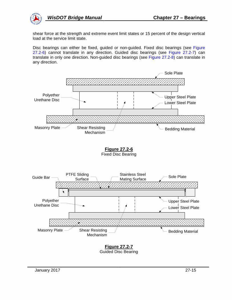
shear force at the strength and extreme event limit states or 15 percent of the design vertical load at the service limit state.
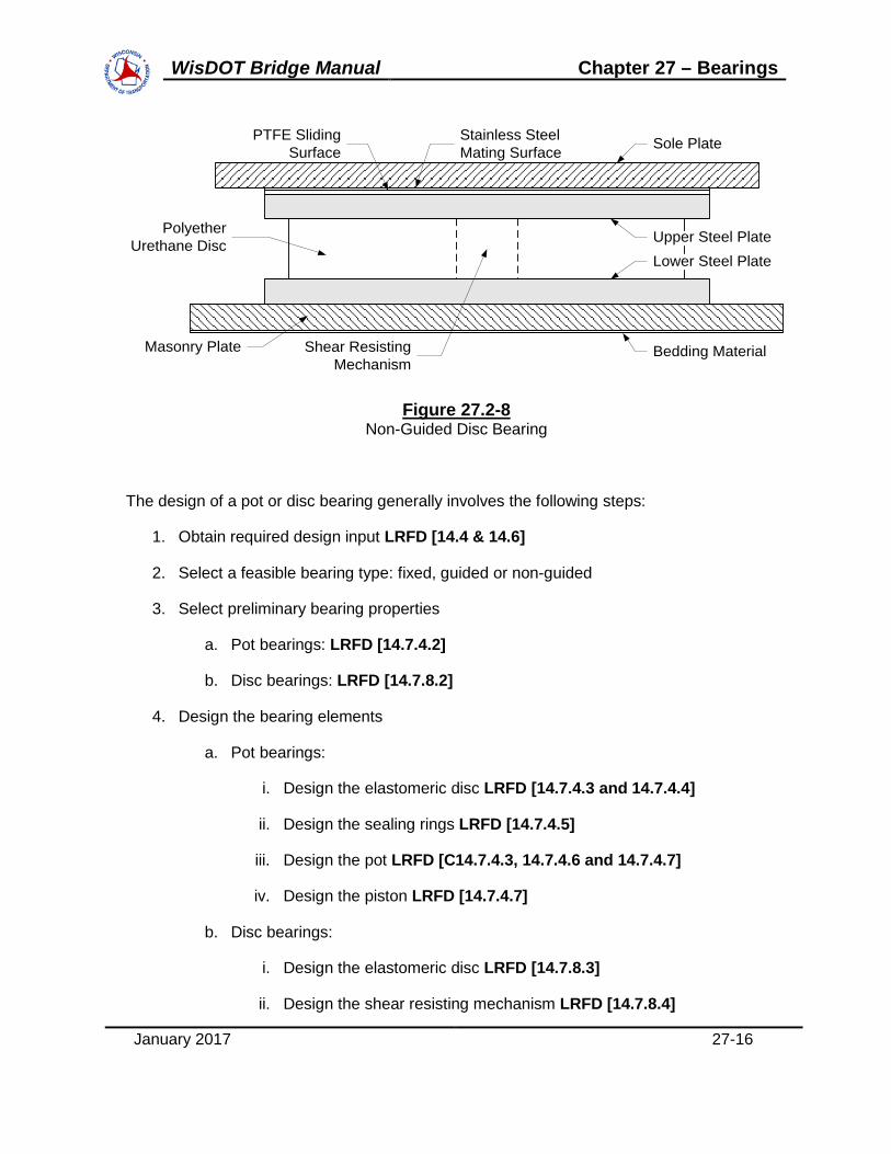
Disc bearings can either be fixed, guided or non-guided. Fixed disc bearings (see Figure 27.2-6) cannot translate in any direction. Guided disc bearings (see Figure 27.2-7) can translate in only one direction. Non-guided disc bearings (see Figure 27.2-8) can translate in any direction.
Sole Plate
Polyether Urethane Disc
Bedding Material Masonry Plate Shear Resisting Mechanism
Upper Steel PlateLower Steel Plate
Figure 27.2-6 Fixed Disc Bearing
Figure 27.2-7 Guided Disc Bearing
Sole Plate
Polyether Urethane Disc
Bedding Material Masonry Plate
Guide Bar Stainless Steel Mating Surface
PTFE Sliding Surface
Upper Steel Plate
Shear Resisting Mechanism
Lower Steel Plate
WisDOT Bridge Manual Chapter 27 – Bearings
January 2017 27-16
Sole Plate
Polyether Urethane Disc
Bedding Material Masonry Plate
Stainless Steel Mating Surface
PTFE Sliding Surface
Upper Steel PlateLower Steel Plate
Shear Resisting Mechanism
Figure 27.2-8 Non-Guided Disc Bearing
The design of a pot or disc bearing generally involves the following steps:
1. Obtain required design input LRFD [14.4 & 14.6]
2. Select a feasible bearing type: fixed, guided or non-guided
3. Select preliminary bearing properties
a. Pot bearings: LRFD [14.7.4.2]
b. Disc bearings: LRFD [14.7.8.2]
4. Design the bearing elements
a. Pot bearings:
i. Design the elastomeric disc LRFD [14.7.4.3 and 14.7.4.4]
ii. Design the sealing rings LRFD [14.7.4.5]
iii. Design the pot LRFD [C14.7.4.3, 14.7.4.6 and 14.7.4.7]
iv. Design the piston LRFD [14.7.4.7]
b. Disc bearings:
i. Design the elastomeric disc LRFD [14.7.8.3]
ii. Design the shear resisting mechanism LRFD [14.7.8.4]
WisDOT Bridge Manual Chapter 27 – Bearings
January 2017 27-17
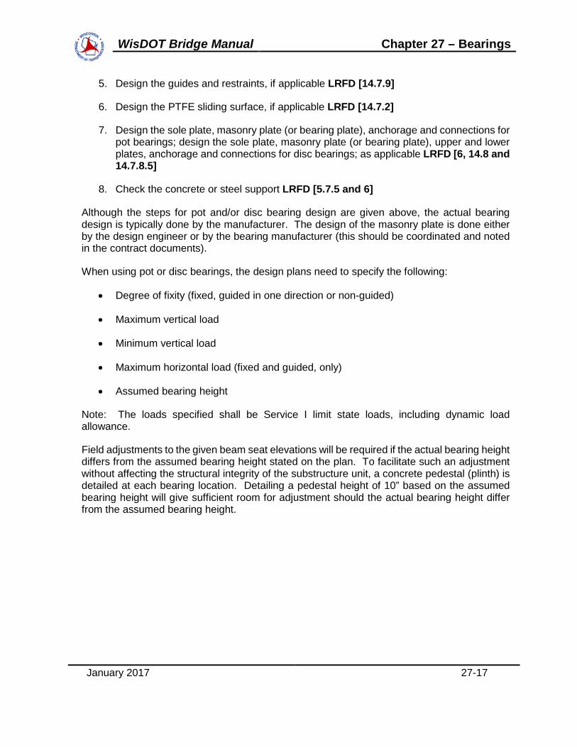
5. Design the guides and restraints, if applicable LRFD [14.7.9]
6. Design the PTFE sliding surface, if applicable LRFD [14.7.2]
7. Design the sole plate, masonry plate (or bearing plate), anchorage and connections for pot bearings; design the sole plate, masonry plate (or bearing plate), upper and lower plates, anchorage and connections for disc bearings; as applicable LRFD [6, 14.8 and 14.7.8.5]
8. Check the concrete or steel support LRFD [5.7.5 and 6]
Although the steps for pot and/or disc bearing design are given above, the actual bearing design is typically done by the manufacturer. The design of the masonry plate is done either by the design engineer or by the bearing manufacturer (this should be coordinated and noted in the contract documents).
When using pot or disc bearings, the design plans need to specify the following:
• Degree of fixity (fixed, guided in one direction or non-guided)
• Maximum vertical load
• Minimum vertical load
• Maximum horizontal load (fixed and guided, only)
• Assumed bearing height
Note: The loads specified shall be Service I limit state loads, including dynamic load allowance.
Field adjustments to the given beam seat elevations will be required if the actual bearing height differs from the assumed bearing height stated on the plan. To facilitate such an adjustment without affecting the structural integrity of the substructure unit, a concrete pedestal (plinth) is detailed at each bearing location. Detailing a pedestal height of 10” based on the assumed bearing height will give sufficient room for adjustment should the actual bearing height differ from the assumed bearing height.
WisDOT Bridge Manual Chapter 27 – Bearings
January 2017 27-18
27.3 Hold Down Devices
Hold down devices are additional elements added to the Type "A-T" bearings for situations where live load can cause uplift at the abutment end of a girder. Ideally, proper span configurations would eliminate the need for hold down devices as they have proven to be a maintenance problem. Details for hold down devices are given in the Standard for Hold Down Devices.

WisDOT Bridge Manual Chapter 27 – Bearings
January 2017 27-19
27.4 Design Example
E27-1 Steel Reinforced Elastomeric Bearing

WisDOT Bridge Manual
This page intentionally left blank.

Table of ContentsE27-1 DESIGN EXAMPLE STEEL REINFORCED ELASTOMERIC BEARING............................................
E27-1.1 Design Data ............................................................................................................E27-1.2 Design Method........................................................................................................E27-1.3 Dynamic Load Allowance .......................................................................................E27-1.4 Shear ......................................................................................................................E27-1.5 Compressive Stress................................................................................................E27-1.6 Stability ...................................................................................................................E27-1.7 Compressive Deflection..........................................................................................E27-1.8 Anchorage ..............................................................................................................E27-1.9 Reinforcement: .......................................................................................................E27-1.10 Rotation: ...............................................................................................................E27-1.11 Bearing summary:.................................................................................................
22223456899
11
WisDOT Bridge Manual Chapter 27 – Bearings

E27-1 DESIGN EXAMPLE - STEEL REINFORCED ELASTOMERIC BEARING
ThIs design example is for a 3-span prestressed girder structure. The piers are fixedsupports and the abutments accommodate expansion.(Example is current through LRFD Seventh Edition - 2016 Interim) |
E27-1.1 Design DataBearing location: Abutment (Type A3)
Girder type: 72W
Lexp 220 Expansion length, ft
bf 2.5 Bottom flange width, ft
DLserv 167 Service I limit state dead load, kips
DLws 23 Service I limit state future wearing surface dead load, kips
LLserv 62 Service I limit state live load, kips
hrcover 0.25 Elastomer cover thickness, in
hs 0.125 Steel reinforcement thickness, in
Fy 36 Minimum yield strength of the steel reinforcement, ksi
Temperature Zone: C (Southern Wisconsin) LRFD [Fig. 14.7.5.2-1]Minimum Grade of Elastomer: 3 LRFD [Table 14.7.5.2-1]Elastic Hardness: Durometer 60 +/- 5 (used 55 for design)Shear Modulus (G): 0.1125 ksi < G <0.165 ksi LRFD [Table 14.7.6.2-1]Creep Deflection @ 25 Yearsdivided by instantaneous deflection: 0.3 LRFD [Table 14.7.6.2-1]
| D (Use for Entire State)| 4
E27-1.2 Design MethodUse Design Method A LRFD [14.7.6]Method A results in a bearing with a lower capacity than a bearing designed using Method B.However the increased capacity resulting from the use of Method B requires additionaltesting and quality control.
E27-1.3 Dynamic Load AllowanceThe influence of impact need not be included for bearings LRFD [14.4.1]; however,dynamic load allowance will be included to follow a WisDOT policy item.
January 2017 27E1-2
WisDOT Bridge Manual Chapter 27 – Bearings

E27-1.4 Shear The maximum shear deformation of the pad shall be taken as the maximum horizontalsuperstructure displacement, reduced to account for the pier flexibility. LRFD [14.7.6.3.4]
hrt 2 Δs LRFD [Equation 14.7.6.3.4-1]
Temperature range: Tlow and Thigh values below are from WisDOT policy item in 27.1
Tlow 5 Minimum temperature, oF
Thigh 85 Maximum temperature, oF
γTU 1.2 Service I Load factor for deformation LRFD [Table 3.4.1-1]
Tinstall 60 Installation temperature, oF
αc 0.000006 Coefficient of thermal expansion of concrete, ft/ft/oF
Scrsh 0.0003 Coefficient of creep and shrinkage of concrete, ft/ft
ΔT Tinstall Tlow ΔT 55 oF
Maximum total shear deformation of the elastomer
Δs Lexp αc ΔT 12 Lexp Scrsh 12 Δs 1.663 in
Required total elastomer thickness
Hrt 2 γTU Δs Hrt 3.992 in
Elastomer internal layer thickness
hri 0.5 in
Required elastomer thickness LRFD [14.7.6.1)
hrcover
hri0.7
hrcover
hri0.5
check "< 0.7, OK"
Determine the number of internal elastomer layers:
nHrt 2 hrcover
hri Note: hrcover 0.25 in
n 6.983 layers
Use: n 7 layers
January 2017 27E1-3
WisDOT Bridge Manual Chapter 27 – Bearings

Total elastomer thickness:
hrt 2 hrcover n hri hrt 4.0 in
Total height of reinforced elastomeric pad:
H hrt n 1( ) hs H 5.000 in
E27-1.5 Compressive Stress
σs_all 1.25 and σs_all 1.25 G S LRFD [14.7.6.3.2]
edge 3 in Transverse distance from the edge of the flange to edge of bearing
W 12 bf 2 edge Transverse dimension W 24 in
LDLserv LLserv
W σs_all Since σs_all
DLserv LLserv
L W
σs_all 1.25 ksi
LDLserv LLserv
W σs_all Longitudinal dimension L 7.633 in
increment 5 in <== Rounding increment
L 10 in
(Use a 1 inch minimum rounding increment for design. For this example, therounding increment is used to increase L dimension to satisfy subsequent stresschecks, etc.)
Determine shape factor for internal layer LRFD [Equation 14.7.5.1-1]
SiL W
2 hri L W( ) Si 7.059
G 0.1125 ksi 0.1125ksi G 0.165ksi
(Verify that LRFD is satisfied for a full range of G values.The minimum G values is used here. See also E27-1.8) 1.25 G Si 0.993 ksi
σsDLserv LLserv
L W σs 0.954 ksi
σs "< 1.25GS, OK"
January 2017 27E1-4
WisDOT Bridge Manual Chapter 27 – Bearings

E27-1.6 Stability
HL3
and HW3
LRFD [14.7.6.3.6]
H 5.000 in
Bearing length check:
Lmin 3 H Lmin 15 in
L 10 in
Use the larger value: L 15 in
Bearing width check:
Wmin 3 H Wmin 15 in
W 24 in
Use the larger value: W 24 in
Revised shape factor and compressive stress for internal layer:
hri 0.5 in
G 0.1125 ksi
SiL W
2 hri L W( ) Si 9.231
1.25 G Si 1.298 ksi
σsDLserv LLserv
L W σs 0.636 ksi
σs "< 1.25GSi, OK"
Check LRFD [C14.7.6.1]: Si2 / n < 20 (for rectangular shape with n > 3)
Si2 / n = (9.231)2 / 8 = 10.7 < 20 "OK"
where n = (7 inter. layers + 1/2 (2 exter. layers)) = 8
January 2017 27E1-5
WisDOT Bridge Manual Chapter 27 – Bearings

Revised shape factor and compressive stress for the cover layer:
hrcover 0.25 in
ScoverL W
2 hrcover L W( ) Scover 18.462 ksi
1.25 G Scover 2.596 ksi
σsDLserv LLserv
L W σs 0.636 ksi
σs "< 1.25GS, OK"
E27-1.7 Compressive Deflection
LRFD [14.7.6.3.3, 14.7.5.3.6]
Average vertical compressive stress:
Average compressive stress due to total load
σs 0.636 ksi
Average compressive stress due to live load
σLLLserv
L W σL 0.172 ksi
Average compressive stress due to dead load
σDDLserv
L W σD 0.464 ksi
Use LRFD [Figure C14.7.6.3.3-1] to estimate the compressive strain in the interior andcover layers. Average the values from the 50 Durometer and 60 Durometer curves toobtain values for 55 Durometer bearings.
January 2017 27E1-6
WisDOT Bridge Manual Chapter 27 – Bearings

DEAD LOAD 9.231 0.464 2.3% 2.1% 2.2%
TOTAL LOAD 9.231 0.636 3.1% 2.7% 2.9%
DEAD LOAD 18.462 0.464 1.8% 1.5% 1.7%
TOTAL LOAD 18.462 0.636 2.2% 1.9% 2.1%COVER
50 DUROMETER
STRAIN
60 DUROMETER
STRAIN
AVERAGE STRAIN
INTERNAL
LAYER LOAD S STRESS (ksi)
Initial compressive deflection of n-internal layers and 2 cover layers under total load:
εint 0.029 Compressive strain in the interior layer
εcover 0.021 Compressive strain in the cover layer
n 7 layers
hri 0.5 in
hrcover 0.25 in
δ n hri εint 2 hrcover εcover Modification of LRFD [Equation 14.7.5.3.6-1]
δ 0.112 in
Initial compressive deflection under dead load:
εintDL 0.022
εcoverDL 0.017
δDL n hri εintDL 2 hrcover εcoverDL δDL 0.086 in
Deflection due to creep:
Cd 0.30 Average value between 50 and 60 Durometer LRFD [Table 14.7.6.2-1]
δCR Cd δDL δCR 0.026 in
Compressive deflection due to live load:
δLL δ δDL δLL 0.027 in
January 2017 27E1-7
WisDOT Bridge Manual Chapter 27 – Bearings

Deflection due to creep and live load: LRFD [C14.7.5.3.6]
δCRLL δCR δLL δCRLL 0.052 in
δCRLL "< 0.125 in., OK"
Initial compressive deflection of a single internal layer:
εint hri 0.09 hri LRFD [14.7.6.3.3] εint 0.029
εint "< 0.09, OK"
E27-1.8 Anchorage LRFD [14.8.3]
Shear force generated in the bearing due to temperature movement:
LRFD [Equation 14.6.3.1-2]Hu G AΔu
hrt
G 0.165 conservative assumption, maximum value of G, ksi
Factored shear deformation of the elastomer
Δu γTU Δs Δu 1.996 in
Plan area of elastomeric element
L 15 in W 24 in
A L W A 360 in2
Hu G AΔu
hrt Hu 29.638 kips
(This value of Hu can be used for substructure design)
Minimum vertical force due to permanent loads:
γDLserv 1.0
Psd γDLserv DLserv DLws Psd 144 kips
σPsd
A σ 0.400 ksi
σ "> 0.200 ksi, OK, anchorage is not required per WisDOT exception to AASHTO"
January 2017 27E1-8
WisDOT Bridge Manual Chapter 27 – Bearings
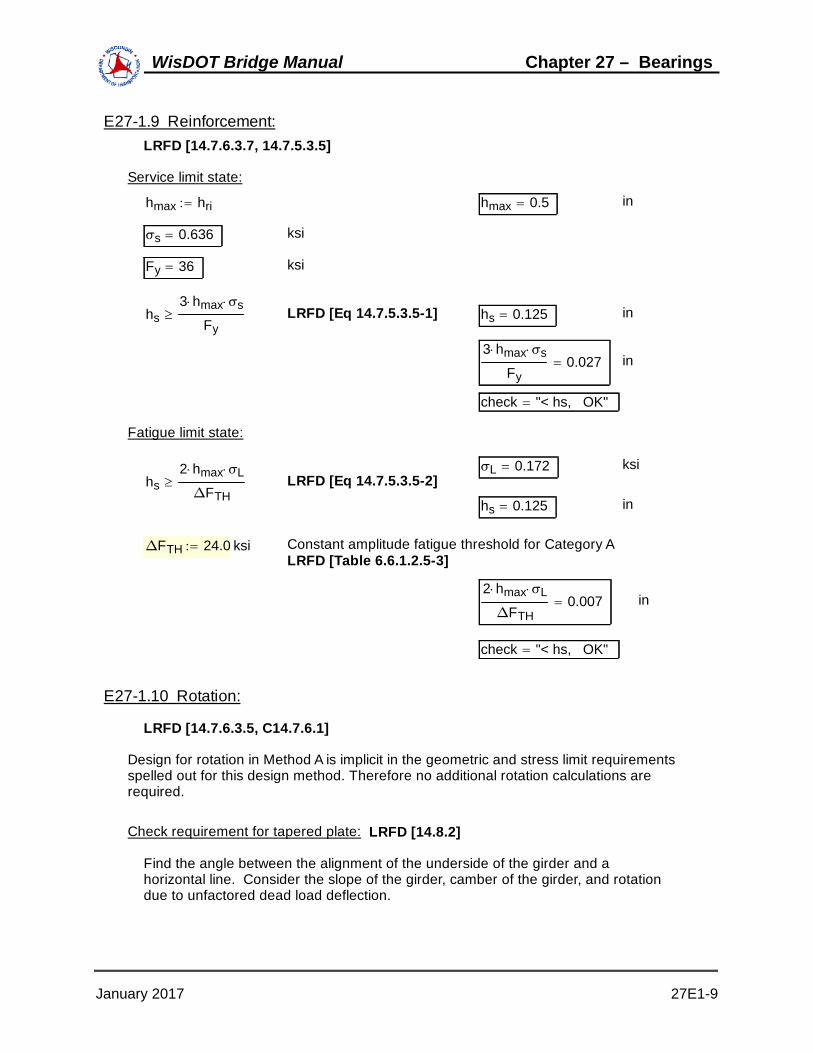
E27-1.9 Reinforcement: LRFD [14.7.6.3.7, 14.7.5.3.5]
Service limit state:
hmax hri hmax 0.5 in
σs 0.636 ksi
Fy 36 ksi
hs3 hmax σs
Fy LRFD [Eq 14.7.5.3.5-1] hs 0.125 in
3 hmax σs
Fy0.027 in
check "< hs, OK"
Fatigue limit state:
σL 0.172 ksihs
2 hmax σL
ΔFTH LRFD [Eq 14.7.5.3.5-2]
hs 0.125 in
ΔFTH 24.0 ksi Constant amplitude fatigue threshold for Category ALRFD [Table 6.6.1.2.5-3]
2 hmax σL
ΔFTH0.007 in
check "< hs, OK"
E27-1.10 Rotation:
LRFD [14.7.6.3.5, C14.7.6.1]
Design for rotation in Method A is implicit in the geometric and stress limit requirementsspelled out for this design method. Therefore no additional rotation calculations arerequired.
Check requirement for tapered plate: LRFD [14.8.2]
Find the angle between the alignment of the underside of the girder and ahorizontal line. Consider the slope of the girder, camber of the girder, and rotationdue to unfactored dead load deflection.
January 2017 27E1-9
WisDOT Bridge Manual Chapter 27 – Bearings

Inclination due to grade line:
Lspan 150 Span length, ft
@ pier:
ELPseat 856.63 Beam seat elevation at the pier, in feet
hPbrg 0.5 Bearing height at the pier, in
Bottom of girder elevation at the pier, in feet
EL1 ELPseathPbrg
12 EL1 856.672
@ abutment:
ELAseat 853.63 Beam seat elevation at the abutment, in feet
tplate 1.5 Steel top plate thickness, in
H 5 Total elastomeric bearing height, in
Total bearing height, at the abutment, in
hAbrg H tplate hAbrg 6.5 in
Bottom of girder elevation in feet
EL2 ELAseathAbrg
12 EL2 854.172
Slope of girder
SGLEL1 EL2
Lspan SGL 0.017
Inclination due to grade line in radians
θGL atan SGL θGL 0.017 radians
Inclination due to residual camber:
Δcamber 3.83 Maximum camber of girder, in
ΔDL 2.54 Maximum dead load deflection, in
ΔLL 0.663 Maximum live load deflection, in
January 2017 27E1-10
WisDOT Bridge Manual Chapter 27 – Bearings
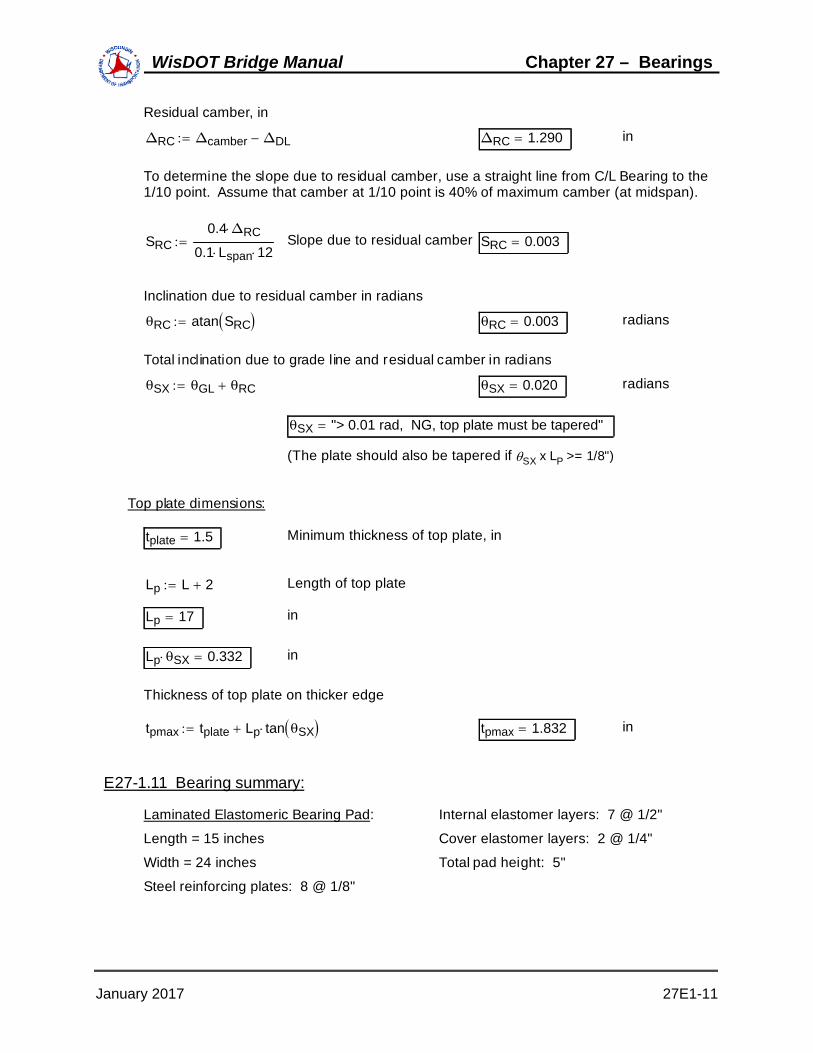
Residual camber, in
ΔRC Δcamber ΔDL ΔRC 1.290 in
To determine the slope due to residual camber, use a straight line from C/L Bearing to the1/10 point. Assume that camber at 1/10 point is 40% of maximum camber (at midspan).
SRC0.4 ΔRC
0.1 Lspan 12 Slope due to residual camber SRC 0.003
Inclination due to residual camber in radians
θRC atan SRC θRC 0.003 radians
Total inclination due to grade line and residual camber in radians
θSX θGL θRC θSX 0.020 radians
θSX "> 0.01 rad, NG, top plate must be tapered"
(The plate should also be tapered if SX x LP >= 1/8")
Top plate dimensions:
tplate 1.5 Minimum thickness of top plate, in
Lp L 2 Length of top plate
Lp 17 in
Lp θSX 0.332 in
Thickness of top plate on thicker edge
tpmax tplate Lp tan θSX tpmax 1.832 in
E27-1.11 Bearing summary:
Laminated Elastomeric Bearing Pad: Internal elastomer layers: 7 @ 1/2"
Length = 15 inches Cover elastomer layers: 2 @ 1/4"
Width = 24 inches Total pad height: 5"
Steel reinforcing plates: 8 @ 1/8"
January 2017 27E1-11
WisDOT Bridge Manual Chapter 27 – Bearings

Steel Top Plate (See standard detail):
Length = 17 inches
Width = 30 inches
Thickness = 1 1/2" to 1 7/8"
January 2017 27E1-12
WisDOT Bridge Manual Chapter 27 – Bearings