chapter 26 survey transmittal - state of indiana
TRANSCRIPT

INDIANA DEPARTMENT OF TRANSPORTATION—2013 DESIGN MANUAL
CHAPTER 26
Survey Transmittal
Design
Memorandum Revision
Date Sections Affected
13-16 Aug. 2013 26-1.01 13-17 Aug. 2013 26-2.0, Figure 26-2D 17-22 Oct. 2017 26-1.01
NOTE: This chapter is currently being re-written and its content will be included in Chapter 106 in the future.

Page 2 2013 Indiana Design Manual, Ch. 26
TABLE OF CONTENTS
TABLE OF CONTENTS ................................................................................................................ 2
LIST OF FIGURES ........................................................................................................................ 2
26-1.0 GUIDELINES AND PROCEDURES ................................................................................ 3 26-1.01 InRoads Format [Rev. Aug. 2013, Oct. 2017] ............................................................. 3
26-1.01(01) Minimum File Requirements [Rev. Aug. 2013, Oct. 2017] .............................. 4 26-1.01(03) Aerial-Survey File Requirements..................................................................... 10
26-1.02 Other Formats ............................................................................................................. 11
26-2.0 OTHER SURVEY INFORMATION [Rev. Aug. 2013] .................................................. 11
FIGURES ...................................................................................................................................... 18 LIST OF FIGURES Figure Title 26-2A Survey Envelope Label 26-2B Miscellaneous Envelope 26-2C Section Corner Reference Card 26-2D Location Control Route Survey Plat Example [Rev. Aug. 2013] 26-2E Sample Disc Label [Rev. Aug. 2013]

2013 Indiana Design Manual, Ch. 26 Page 3
CHAPTER 26 [Rewritten Apr. 2011]
SURVEY TRANSMITTAL Transmitting accurate and consistently-formatted survey data to the designer will facilitate an efficient and cost-effective project design. Regardless of the survey method, each electronic survey-data submission shall be in a format that is compatible with INDOT’s current versions of survey and design software in use. Each submission shall be compatible with InRoads design and survey software. However, with prior written approval from INDOT, a consultant may be permitted to submit electronic files that are in accordance with previously-accepted formats on a project by project basis (See Section 26-1.02). If the survey submittal is for a design consultant’s CADD system, the files may be transmitted in a format compatible with the consultant’s design application. However, a submittal of the survey data shall also be provided to INDOT that is compatible with INDOT’s current software. A complete survey transmittal should incorporate all relevant survey information, whether electronic or not. This Chapter provides the content, style, and format requirements for a survey transmittal that is acceptable to INDOT. The guidelines and procedures described herein also include the types of files and the documentation formats that should be utilized in project design. 26-1.0 GUIDELINES AND PROCEDURES Providers of land-surveying services are required to embrace current technology to improve the quality, consistency, and accuracy of survey data collected in the field and to satisfy INDOT standards. To effectively and efficiently exchange electronic information, INDOT requires standardized file formats that provide compatibility between data collectors, data processors, and data users; and which allow for future reuse of the data by INDOT or its consultants. 26-1.01 InRoads Format [Rev. Aug. 2013, Oct. 2017] INDOT adopted Microstation and InRoads as its standard drafting and design software applications, respectively, the CAD Support Team has developed standard resource files such as design templates (seed files) and survey-data processing (.xin) files. The most current INDOT seed.dgn and survey.xin files made available through the CAD Support Team shall be used. INDOT has established a standard naming convention for all InRoads survey files to make the data more portable so that all users can easily recognize and use the files created by others. The
Page 4 2013 Indiana Design Manual, Ch. 26
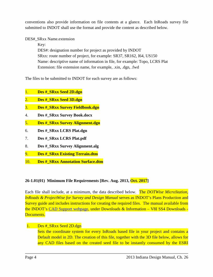
conventions also provide information on file contents at a glance. Each InRoads survey file submitted to INDOT shall use the format and provide the content as described below. DES#_SRxx Name.extension Key: DES#: designation number for project as provided by INDOT SRxx: route number of project, for example: SR37, SR162, I64, US150
Name: descriptive name of information in file, for example: Topo, LCRS Plat Extension: file extension name, for example, .xin, .dgn, .fwd The files to be submitted to INDOT for each survey are as follows:
1. Des #_SRxx Seed 2D.dgn
2. Des #_SRxx Seed 3D.dgn
3. Des #_SRxx Survey Fieldbook.dgn
4. Des #_SRxx Survey Book.docx
5. Des #_SRxx Survey Alignment.dgn
6. Des #_SRxx LCRS Plat.dgn
7. Des #_SRxx LCRS Plat.pdf
8. Des #_SRxx Survey Alignment.alg
9. Des #_SRxx Existing Terrain.dtm
10. Des #_SRxx Annotation Surface.dtm
26-1.01(01) Minimum File Requirements [Rev. Aug. 2013, Oct. 2017] Each file shall include, at a minimum, the data described below. The DOTWise MicroStation, InRoads & ProjectWise for Survey and Design Manual serves as INDOT’s Plans Production and Survey guide and includes instructions for creating the required files. The manual available from the INDOT’s CAD Support webpage, under Downloads & Information – V8I SS4 Downloads - Documents. 1. Des #_SRxx Seed 2D.dgn
Sets the coordinate system for every InRoads based file in your project and contains a Default model in 2D. The creation of this file, together with the 3D file below, allows for any CAD files based on the created seed file to be instantly consumed by the ESRI

2013 Indiana Design Manual, Ch. 26 Page 5
ArcGIS Products and made available for a variety of other uses. With OpenRoads changes to document handling and civil information, files for both 2D and 3D will be created (DOTWise 6.3-1).
2. Des #_SRxx Seed 3D.dgn
Sets the coordinate system for every InRoads based file in your project and contains a Default model in 3D. (DOTWise 6.3-1).
3. Des #_SRxx Survey Fieldbook.dgn. This file contains field book information for TOPO
and Control Points in the OpenRoads format (survey field book) along with the existing terrain model. No alignments or civil geometry are created in this file. Alignments and civil geometry will be created as a 3D model. (DOTWise 6.3-3). This file includes centerline points, a partial list of fly stations (random control points), bench marks, and United States Public Land Survey (USPLS) subdivision corners, including corners of properties not within USPLS areas, necessary to describe acquisition parcels. a. Centerline Points. All centerline points of each survey line within the survey shall
be included in this file.
(1) The code for centerline points shall be “PSSA”.
(2) Notes for each “PSSA” shall include location (e.g., POT, PC, POST, etc.) stationing, line letter, PI information (delta angle, degree of curve or radius length, tangent length, arc length, and external length), description of monument, and location of top of monument relative to ground surface or pavement surface.
b. Fly station. All fly stations traversed through, during establishment or reestablishment of survey lines, shall be included in this file.
The code for fly station shall be “FLY”. Notes for “FLY” shall include the description of the monument and location of top of monument relative to ground surface or pavement surface for each point.
c. Bench Marks. Those used for survey data collection shall be included in this file.
(1) Monuments shall be coded in accordance with the .xin and .dgnlib files provided by INDOT.

Page 6 2013 Indiana Design Manual, Ch. 26
(2) Bench mark notes shall include the name and description of each monument, a description of the structure that the monument is placed in or on, the station and offset from the survey line, and the survey-line letters.
Examples: TBM#1, Boat Spike in root of 21-in. oak tree, 125 ft left of Station 123+45, Line “A”. INDOT BM 19 V 1030, disc in north end of concrete headwall, 55 ft right of Station 35+25, Line “S-1-A”.
d. USPLS Corners. These, or corners of properties not within USPLS areas, necessary to describe acquisition parcels, shall be included in this file.
(1) Monuments shall be coded in accordance with the .xin and .dgnlib files provided by INDOT.
(2) Notes for monuments shall include the location of the corner.
Example for area within USPLS: “N ¼ Corner of Section 34, T2N, R2W”. Example for area not within USPLS: “NE Corner of Division “C” of the Vincennes Commons Lands”.
(3) Notes shall include a description and location of each monument relative to the ground surface or pavement surface.
4. Des #_SRxx Survey Book.docx. This file includes all supplemental survey information not found in other files. The .docx format is preferred. However, .doc or .pdf is also acceptable. It shall include the following: a. front page notations, i.e., Des No., Route No., Terminal Points of Project, County,
brief description of each line; b. title page and completed Table of Contents; c. dates of survey start and survey completion; d. names of survey crew members; e. Des number and page numbers at top of each page; f. Surveyors Report, in accordance with IAC-865, as a minimum requirement; g. start and end of each line shown with equations and cross references to other
surveys;

2013 Indiana Design Manual, Ch. 26 Page 7
h. control points labeled, with location (e.g., POT, PC, POST, etc.), stationing, line
letters, location relative to surface (e.g. flush, 0.1’ below ground level, etc.), and coordinates shown;
i. alignment data shown and checked; j. references shown and checked, if LCRS not prepared. If an LCRS was prepared,
this information will be on the recorded LCRS; k. source of bearings described; l. utility ownerships within limits of survey, with mailing addresses, with a notation
of utilities not within limits; m. Underground Utility Reference Number placed on Utilities page; n. high-water elevation and date, with source and date of information; o. source of level datum; p. bench-mark descriptions completed; q. level notes for all bench marks used for survey; r. legal flow-line elevations of county ditches; and s. level equations with other surveys shown, and explained.
5. Des #_SRxx Survey Alignment.dgn. This file contains the survey alignment(s) in the OpenRoads format (civil data – linear elements). This file will be created as a 2D model. (DOTWise 6.3-7).
6. Des #_SRxx LCRS Plat.dgn. This file shall include multiple models of the following. DOTWise a. The LCRS used to generate that for recording with the County Recorder. This
shall be provided for design reference and use. b. Survey control points and references, which include the following:
Page 8 2013 Indiana Design Manual, Ch. 26
(1) description of point along alignment (e.g., POT, PC, POST, etc.);
(2) stationing of survey-line point (e.g., 123+45.67, etc.); (3) line letter (e.g., “A”, “S-1-A”, etc.); (4) description of monument (e.g., 5/8 in. rebar with cap stamped INDOT
0005, Mag Nail with washer stamped INDOT 0005, etc.); (5) location of top of monument relative to ground surface (e.g., Flush with
surface, 0.1 ft below ground surface, protruding 0.4 ft above ground surface, etc.);
(6) description of reference monument (e.g., Nail in Bottle Cap in 15-in.
Maple, Nail in Bottle Cap in Corner Fence Post, X Cut in Concrete Headwall, etc.); and
(7) azimuth to nearest degree, and distance to nearest 0.01 ft, from control
monument to reference monument. c. USPLS corners, or corners within areas not part of the USPLS, and references,
including, at a minimum, the following:
(1) descriptions of USPLS corners (e.g., W ¼ Corner of Section 24, T3N, R5W);
(2) descriptions of monuments not within USPLS areas (e.g., NE Corner of
Division “C” of the Vincennes Commons Lands); (3) description of monument (e.g., 9” x 6” stone with “S 24 W ¼” cut on side
of stone); (4) location of top of monument relative to ground surface (e.g., Flush with
surface, 1.5 ft below ground surface, protruding 0.7 ft above ground surface, etc.);
(5) description of reference monument (e.g., Nail in Bottle Cap in 15-in.
Maple, Nail in Bottle Cap in Corner Fence Post, X Cut in Concrete Headwall, etc); and

2013 Indiana Design Manual, Ch. 26 Page 9
(6) Azimuth, to the nearest degree, and distance, to the nearest 0.01 ft, from control monument to reference monument.
7. Des #_SRxx LCRS Plat.pdf. This file is a copy of the Location Control Route Survey
Plat (LCRS) as recorded in the County Recorder’s office, for the survey project. This copy shall have the seal and signature of the Licensed Land Surveyor in responsible charge, and all recording information placed on the LCRS by the County Recorder.
8. Des #_SRxx Survey Alignment.alg. InRoads Survey Alignments, Legacy format for annotation. (DOTWise 6.3-5). This file includes all alignments of the survey project. a. In writing Survey to Geometry, in the “Project Name” box, enter “Survey
Alignment“. b. In creating alignment, in “Name” box, enter “A” for Line “A”, etc. c. If there is an “S” line, under “Survey Alignment”, name alignment “S-1-A”, “S-
SRxx-A”, etc. d. For the description of each alignment, use the applicable route name (e.g., SR 1,
CR 250 W, etc.). e. The alignment shall have the correct stationing applied. f. Save as “Des #_SRxx Survey Alignment.alg”
9. Des #_SRxx Existing Terrain.dtm InRoads DTM of Survey terrain model, with applicable triangulation cleanup. This model will only contain the existing triangulated terrain and any features that are included in that triangulation. The model can be used with the native InRoads tools for 3D analysis as it will match the OpenRoads existing terrain. (DOTWise 6.3-5)
10. Des #_SRxx Annotation Surface.dtm InRoads DTM of Survey processed features, Legacy format for annotation. This should not be used for any functions beyond the native annotation tools and should be created using the import process. (DOTWise 6.3-6)

Page 10 2013 Indiana Design Manual, Ch. 26
26-1.01(02) Additional Geo-Coordination Files [Added Aug. 2013] Two additional files that are directly correlated with the DGN geo-coordination seed file shall also be included in the survey transmittal as follows: 1. IN_GeoCS.dty The delivered file will contain the appropriate coordinate systems.
a. This is the base customized geo-coordination library to be used with Bentley Map and the creation of geo-coordination survey seed files.
b. This file should be used with the Microstation MS_GEOCOORDINATE_USERLIBRARIES variable.
c. The template file will be edited as necessary, and then saved. 2. esri_cad.wld This file contains the necessary parameters to transform the DGN to the
State Plane Coordinate (SPC) system.
a. The data in this file allows the file to be re-projected on-the-fly to its appropriate location on the ground in the real world.
b. The data in the WLD file will consist of the Local Ground Coordinates for two well-established control points and the corresponding SPC for the same two points. The two control points should be located such that one is outside the limits of construction at the start of the project, and the other will be at a similar location beyond the end of the project construction.
Procedures for accessing, properly editing, and creating the above described files can be found in the current version of DOTWise MicroStation, InRoads & ProjectWise for Survey and Design Manual available on the INDOT CAD Support webpage. The required templates referenced in the instructional documentation are also available on the INDOT CAD Support webpage and are located under the Geo-Coordination tab. 26-1.01(03) Aerial-Survey File Requirements 1. All files created by an aerial survey shall follow the established InRoads survey file
naming and technical conventions. 2. In naming these files, they shall have the suffix “_Aerial” appended at the end of the file
name, prior to the file extension, i.e., “Des #_SRxx Topo_Aerial.fwd”.

2013 Indiana Design Manual, Ch. 26 Page 11
3. If a combination of aerial and ground surveys is submitted, they shall be combined into a single .dtm survey surface.
26-1.02 Other Formats Although it is preferred for collected survey data to be submitted in the InRoads format as described above, there can be a project or circumstance that necessitates the use of previously-accepted data-submittal formats. For this situation, approval to collect and transmit electronic survey data in a format other than the current version of survey and design software in use must be obtained from INDOT. A written request must be submitted to the appropriate designer and survey-program director through the project manager. Approval will be required prior to the start of field work. 26-2.0 OTHER SURVEY INFORMATION [REV. AUG. 2013] A complete survey transmittal includes other survey information that is relevant to the project. This is described below. A submittal may be downloaded directly into the INDOT Electronic Records management System (ERMS) or the current version of INDOT’s electronic document repository. However, each submittal shall include the minimum amount of information as outlined below, whether in electronic format, hardcopy, or a combination of the two. 1. Survey-Envelope Contents. The survey envelope should be a 9-in. x 12-in. manila
envelope, or comparable type. It shall include all property-owner-interview sheets and the recorded LCRS. All other information should be packaged in a separate envelope and submitted with the completed survey.
Figure 26-2A, Survey-Envelope Label, illustrates how the survey envelope should be labeled. The outside of the survey envelope should include the following:
a. route number and location description as it appears on the schedule sheet; b. designation number; c. project number, if available; d. structure number, if applicable; e. county; f. district; g. date of survey; h. survey-party personnel, with designated party chief; and i. list of envelope contents.

Page 12 2013 Indiana Design Manual, Ch. 26
2. Survey Book. The survey book, a hardcopy or .pdf version, shall be submitted with the final survey materials.
3. Miscellaneous Envelope. See Figure 26-2B, Miscellaneous Envelope. The
miscellaneous envelope should be placed in the back of the survey book and should include the following:
a. copies of section plats to indicate adjoining property owners;
b. copies of digital photographs; and c. section-corner reference cards (see Figure 26-2C). 4. Property Deeds. Property deeds that are within the survey limits and those deeds which
appear necessary for other reasons shall be obtained by the survey party. Property deeds shall be submitted with the field survey and forwarded to the Office of Real Estate.
5. Subdivision Plat. Subdivision plats and town plats, if applicable, should be placed in the
envelope that is submitted to the Department. 6. LCRS. A Location Control Route Survey (LCRS), and the associated LCRS plat, are
required for an INDOT project that requires the purchase of right of way. The LCRS shall, at a minimum, comply with the requirements established by IAC 865 when conducting a route survey. A copy of the recorded LCRS plat is required for use by the Office of Real Estate. The recorded LCRS plat shall be submitted on 24” x 36” media (see Section 14-3.03); however the exact size of the recorded document is subject to requirements of the appropriate Office of the County Recorder. See Figure 26-2D, Location Control Route Survey Plat Example. The following guidelines are intended to aid in developing an LCRS to satisfy IAC 865, but are not intended to replace the surveyor’s judgment as to what should appear in the survey.
a. The LCRS plat size may be reduced to satisfy specific requirements for
recordation. The reduction should be considered in choosing font sizes and line thickness for the original-sized version.
b. Indicate the scale along with a graphical representation of the scale. A standard
engineering scale shall be utilized. Consideration shall be made to ensure legibility at reduced scale that may be required for recordation. See Section 14-3.05(01).

2013 Indiana Design Manual, Ch. 26 Page 13
c. Indicate the location of the project by identifying all roads on the plat. If no intersecting roads are within the project limits, include a description for the location in the surveyor’s report.
d. Units shall be in US Survey feet. The U.S. Survey foot is defined based on 1 m =
39.37 in. The following conversion factor will be utilized:
1 meter = 3.280833333 U.S Survey feet.
e. Show all edges of pavement, fences, centerline points found or set, approximate locations of apparent property lines, buildings, etc. INDOT uses a separate plat for the LCRS and the Right of Way plat. For the LCRS, showing the right of way is not required. Only physical evidence of right of way is shown. The property lines shown on the field plat are for graphical representation only. They are not intended for a property retracement and may not be to scale.
f. Indicate all centerline points, random control points, and reference baseline points
that are set. The stationing used on the centerline should be shown and the basis of the stationing indicated in the surveyor’s report. Section corners should also be graphically indicated on the plat where feasible due to scale considerations. All points should have references drawn according to the type of monument (e.g., centerline, section corner, subdivision corner, survey marker, etc.). The arrow for a centerline point indicates the direction of the alignment. For a section corner, the arrow indicates the direction for north. This should be shown in the reference boxes. See Figure 26-2D, Location-Control Route-Survey Plat Example.
g. Indicate as to whether the monument was found or set, and include a description
in the surveyor’s report. This should include the size, type of monument, vertical description (e.g., flush, buried, protruding), location to physical features around the monument, origin (if known), uncertainty, etc.
h. The location of the monument can be identified with an angle and distance,
station and offset, or a coordinate system. Coordinates shall be reproducible with the information contained on the LCRS. Include all necessary information so that this may be accomplished. INDOT uses an assumed ground coordinate system. . However, survey control ties shall be referenced to the Indiana State Plane Coordinate System. The metadata required and identified in 865 IAC Rule 12 in referencing state plane coordinates or utilizing Global Positioning System (GPS) shall be included.
Page 14 2013 Indiana Design Manual, Ch. 26
i. Copies of all road and/or bridge plans, both INDOT and local, within the area of the survey being conducted, shall be obtained prior to the start of the survey. If there are existing plans for the area, the survey alignment shown on said plans shall be reestablished and used for the survey being conducted. If plans are not available, a survey alignment shall be established in a close approximation of the center of present roadway. If a new roadway is proposed, the survey alignment shall be established based upon project location scope and corridor requirements. Survey alignments, established or reestablished, shall have monuments at all PCs, PIs, PTs, POTs, and intersections with other survey alignments. These monuments shall be any combination of the following:
1) original survey alignment monument; 2) monument set (where possible and practical); or 3) monument that is not an original survey alignment monument, but is
accepted as marking the original location. The surveyor’s opinion as to the amount (in feet) of uncertainty of marking original location shall be provided.
j. Monuments shall be set on the survey alignment at intervals that typically do
not exceed one quarter (1/4) mile from the nearest survey alignment monument. Said monuments shall be shown on the LCRS plat. A statement regarding the surveyor’s opinion of cause and amount (in feet) of uncertainty associated with the reestablished survey alignment and stationing shall be provided on the LCRS plat.
k. The basis of bearings shall be on State Plane Coordinate (SPC) grid bearings.
Local Ground Coordinates (LGC) shall be used for survey alignment data, topography, PLSS corners, and basis of all distances shown on the LCRS plat.
l. The monuments, as listed below, shall be shown on the LCRS plat with both a
LGC and SPC for each of the following:
1) PLSS corner monuments; 2) survey alignment monuments; 3) monuments that appear to locate property ownership; 4) monuments used as a basis of translation between LGC and SPC; and 5) monuments located along roadway used to collect topographic details for
the survey.

2013 Indiana Design Manual, Ch. 26 Page 15
m. The LGC shall be derived from an SPC that is converted to ground coordinates and translated, without rotation, to coordinate values smaller than SPCs, thereby not being mistaken as an SPC, and also having a value that, if the survey is extended, the LGC will not result in a negative value. This LGC shall not have the appearance of being a truncated SPC.
n. The following information shall be shown on the recorded LCRS plat:
1) the point number, with both SPC and LGC, used for translating SPC to LGC;
2) the Combined Scale Factor (CSF), being the product of the Scale Factor and the Elevation Factor, used to translate an SPC to an LGC;
3) the formula used to convert data from LGC to an SPC; and 4) the name, datum tag, and epoch date [for example, NAD83(2011) epoch
2010.00] used for GNSS data acquisition. o. Control monuments (coded PGPS for INDOT InRoads formatting) shall be set in
an area near the roadway that would facilitate a direct GNSS observation. An existing found monument, meeting the parameters described herein, may be substituted as a control monument. The established SPC for each control monument, whether set or found, shall not be derived from or based on a traverse. Control monuments shall be located outside construction limits at the start of the project and at a similar location beyond the end of the project construction. Both the SPC and LGC for said control monuments shall be shown on the LCRS plat.
p. Precisions called for below are not an indication that they can be achieved, but
only to assist in the conversions from LGCs to SPCs.
1) LGCs and SPCs shall be shown to four (4) digits to the right of the decimal when in US Survey feet, and five (5) digits to the right of the decimal when in meters. 2) Latitude and Longitude shall be shown in degrees, minutes, seconds (DMS) format, with seconds shown to six (6) places to the right of the decimal. 3) Combined Scale Factor (CSF) shall be shown to ten (10) places to the right of the decimal.
q. Show the property owners’ names on the plat at the time of the survey.
r. Include all title-block information known at the time the plat is transmitted to the
Office of Real Estate.

Page 16 2013 Indiana Design Manual, Ch. 26
7. Recorded Plats. The recorded surveys that were obtained from the recorder’s office
should be submitted with the survey. 8. Plans. Copies of plans that have been obtained from the Central Office, district office, or
other sources should also be submitted to INDOT. 9. Electronic Data Submittal. All data or information submitted in digital format shall be
copied to and stored on compact disc or digital video disc optical storage media, a copy of which shall be included with the submittal. A submittal can require larger memory storage capacity. If so, approval to submit data on media other than standard discs must be obtained prior to submittal. All submitted discs shall be labeled with the appropriate route number, designation number, location description, survey start and finish dates, and disc number. Disc labels shall not be hand written. The text on the label shall be in the Arial font with a minimum point size of 10. See Figure 26-2E.

2013 Indiana Design Manual, Ch. 26 Page 17

Page 18 2013 Indiana Design Manual, Ch. 26
FIGURES
26-2A Survey Envelope Label

2013 Indiana Design Manual, Ch. 26 Page 19
26-2B Miscellaneous Envelope

Page 20 2013 Indiana Design Manual, Ch. 26
26-2C Section Corner Reference Card

2013 Indiana Design Manual, Ch. 26 Page 21
26-2D Location Control Route Survey Plat Example [Rev. Aug. 2013]

Page 22 2013 Indiana Design Manual, Ch. 26

2013 Indiana Design Manual, Ch. 26 Page 23
26-2E Sample Disc Label [Rev. Aug. 2013]