chapter 24 - department of physicsconditions for interference for sustained interference between two...
TRANSCRIPT

Chapter 24
Wave Optics

Wave Optics
The wave nature of light is needed to explain various phenomena
InterferenceDiffractionPolarization
The particle nature of light was the basis for ray (geometric) optics

Interference
Light waves interfere with each other much like mechanical waves doAll interference associated with light waves arises when the electromagnetic fields that constitute the individual waves combine

Conditions for InterferenceFor sustained interference between two sources of light to be observed, there are two conditions which must be met
The sources must be coherentThey must maintain a constant phase with respect to each other
The waves must have identical wavelengths

Producing Coherent Sources
Light from a monochromatic source is allowed to pass through a narrow slitThe light from the single slit is allowed to fall on a screen containing two narrow slitsThe first slit is needed to insure the light comes from a tiny region of the source which is coherent

Producing Coherent Sources, cont
Currently, it is much more common to use a laser as a coherent sourceThe laser produces an intense, coherent, monochromatic beam over a width of several millimetersThe laser light can be used to illuminate multiple slits directly

Young’s Double Slit Experiment
Thomas Young first demonstrated interference in light waves from two sources in 1801Light is incident on a screen with a narrow slit, So
The light waves emerging from this slit arrive at a second screen that contains two narrow, parallel slits, S1 and S2

Young’s Double Slit Experiment, Diagram
The narrow slits, S1 and S2 act as sources of wavesThe waves emerging from the slits originate from the same wave front and therefore are always in phase

Resulting Interference Pattern
The light from the two slits form a visible pattern on a screenThe pattern consists of a series of bright and dark parallel bands called fringesConstructive interference occurs where a bright fringe appearsDestructive interference results in a dark fringe

Fringe Pattern
The fringe pattern formed from a Young’s Double Slit Experiment would look like thisThe bright areas represent constructive interferenceThe dark areas represent destructive interference

Interference Patterns
Constructive interference occurs at the center pointThe two waves travel the same distance
Therefore, they arrive in phase, thus we get a bright area

Interference Patterns, 2The upper wave has to travel farther than the lower waveThe upper wave travels one wavelength farther
Therefore, the waves arrive in phase
A bright fringe occurs

Interference Patterns, 3The upper wave travels one-half of a wavelength farther than the lower waveThe trough of the bottom wave overlaps the crest of the upper waveThis is destructive interference
A dark fringe occurs

Interference Equations
The path difference, δ, is found from the tan triangleδ = r2 – r1 = d sin θ
This assumes the paths are parallelNot exactly parallel, but a very good approximation since L is much greater than d
Interference Equations, 2For a bright fringe, produced by constructive interference, the path difference must be either zero or some integral multiple of the wavelengthδ = d sin θbright = m λ
m = 0, ±1, ±2, …m is called the order number
When m = 0, it is the zeroth order maximumWhen m = ±1, it is called the first order maximum

Interference Equations, 3The positions of the fringes can be measured vertically from the zeroth order maximumy = L tan θ ≈ L sin θAssumptions
L>>dd>>λ
Approximationθ is small and therefore the approximation tan θ ≈ sin θ can be used

Interference Equations, 4
When destructive interference occurs, a dark fringe is observedThis needs a path difference of an odd half wavelengthδ = d sin θdark = (m + ½) λ
m = 0, ±1, ±2, …

Interference Equations, final
For bright fringes
For dark fringes
0, 1, 2bright
Ly m m
dλ
= = ± ± K
10, 1, 2
2dark
Ly m m
dλ ⎛ ⎞= + = ± ±⎜ ⎟
⎝ ⎠K

Uses for Young’s Double Slit Experiment
Young’s Double Slit Experiment provides a method for measuring wavelength of the lightThis experiment gave the wave model of light a great deal of credibility
It is inconceivable that particles of light could cancel each other

Lloyd’s MirrorAn arrangement for producing an interference pattern with a single light sourceWave reach point P either by a direct path or by reflectionThe reflected ray can be treated as a ray from the source S’ behind the mirror

Interference Pattern from the Lloyd’s Mirror
An interference pattern is formed The positions of the dark and bright fringes are reversed relative to pattern of two real sourcesThis is because there is a 180° phase change produced by the reflection

Phase Changes Due To Reflection
An electromagnetic wave undergoes a phase change of 180° upon reflection from a medium of higher index of refraction than the one in which it was traveling
Analogous to a reflected pulse on a string

Phase Changes Due To Reflection, cont
There is no phase change when the wave is reflected from a boundary leading to a medium of lower index of refraction
Analogous to a pulse in a string reflecting from a free support

Interference in Thin Films
Interference effects are commonly observed in thin films
Examples are soap bubbles and oil on water: we see different colors on the bubbles because colors have different wavelengths and produce different interference patterns
The interference is due to the interaction of the waves reflected from both surfaces of the film

Interference in Thin Films, 2
Facts to rememberAn electromagnetic wave traveling from a medium of index of refraction n1 toward a medium of index of refraction n2 undergoes a 180° phase change on reflection when n2 > n1
There is no phase change in the reflected wave if n2 < n1
The wavelength of light λn in a medium with index of refraction n is λn = λ/n where λ is the wavelength of light in vacuum

Interference in Thin Films, 3
Ray 1 undergoes a phase change of 180° with respect to the incident rayRay 2, which is reflected from the lower surface, undergoes no phase change with respect to the incident wave
Interference in Thin Films, 4
Ray 2 also travels an additional distance of 2t before the waves recombineFor constructive interference
2nt = (m + ½ ) λ m = 0, 1, 2 …This takes into account both the difference in optical path length for the two rays and the 180° phase change
For destruction interference2 n t = m λ m = 0, 1, 2 …

Interference in Thin Films, 5
Two factors influence interferencePossible phase reversals on reflectionDifferences in travel distance
The conditions are valid if the medium above the top surface is the same as the medium below the bottom surface!! If the thin film is between two different media, one of lower index than the film and one of higher index, the conditions for constructive and destructive interference are reversed

Interference in Thin Films, final
Be sure to include two effects when analyzing the interference pattern from a thin film
Path lengthPhase change

Newton’s RingsAnother method for viewing interference is to place a planoconvex lens on top of a flat glass surfaceThe air film between the glass surfaces varies in thickness from zero at the point of contact to some thickness tA pattern of light and dark rings is observed
This rings are called Newton’s RingsThe particle model of light could not explain the origin of the rings
Newton’s Rings can be used to test optical lenses

Problem Solving Strategy with Thin Films, 1
Identify the thin film causing the interferenceDetermine the indices of refraction in the film and the media on either side of itDetermine the number of phase reversals: zero, one or two

Problem Solving with Thin Films, 2
The interference is constructive if the path difference is an integral multiple of λ and destructive if the path difference is an odd half multiple of λ
The conditions are reversed if one of the waves undergoes a phase change on reflection

Problem Solving with Thin Films, 3
Equation 1 phase reversal
0 or 2 phase reversals
2nt = (m + ½) λ constructive destructive
2nt = m λdestructive constructive

Interference in Thin Films, Example
An example of different indices of refractionA coating on a solar cellThere are two phase changes,one on each reflection

DiffractionHuygen’s principle requires that the waves spread out after they pass through slitsThis spreading out of light from its initial line of travel is called diffraction
In general, diffraction occurs when waves pass through small openings, around obstacles or by sharp edges

Diffraction, 2A single slit placed between a distant light source and a screen produces a diffraction pattern
It will have a broad, intense central bandThe central band will be flanked by a series of narrower, less intense secondary bands
Called secondary maxima
The central band will also be flanked by a series of dark bands
Called minima

Diffraction, 3The results of the single slit cannot be explained by geometric optics (ray tracing)
Geometric optics would say that light rays traveling in straight lines should cast a sharp image of the slit on the screen

Single Slit DiffractionAccording to Huygen’s principle, each portion of the slit acts as a source of wavesThe light from one portion of the slit can interfere with light from another portionThe resultant intensity on the screen depends on the direction θ
Single Slit Diffraction, 2All the waves that originate at the slit are in phaseWave 1 travels farther than wave 3 by an amount equal to the path difference (a/2) sin θIf this path difference is exactly half of a wavelength, the two waves cancel each other and destructive interference results

Single Slit Diffraction, 3
In general, destructive interference occurs for a single slit of width a when sin θdark = mλ / a
m = ±1, ±2, ±3, …
Doesn’t give any information about the variations in intensity along the screen

Single Slit Diffraction, 4The general features of the intensity distribution are shownA broad central bright fringe is flanked by much weaker bright fringes alternating with dark fringesThe points of constructive interference lie approximately halfway between the dark fringes

Polarization of Light Waves
Each atom produces a wave with its own orientation of All directions of the electric field vector are equally possible and lie in a plane perpendicular to the direction of propagationThis is an unpolarized wave
Er

Polarization of Light, cont
A wave is said to be linearly polarized if the resultant electric field vibrates in the same direction at all times at a particular pointPolarization can be obtained from an unpolarized beam by
selective absorptionreflectionscattering

Polarization by Selective Absorption
The most common technique for polarizing lightUses a material that transmits waves whose electric field vectors in the plane are parallel to a certain direction and absorbs waves whose electric field vectors are perpendicular to that direction

Selective Absorption, contE. H. Land discovered a material that polarizes light through selective absorption
He called the material PolaroidThe molecules readily absorb light whose electric field vector is parallel to their lengths and transmit light whose electric field vector is perpendicular to their lengths

Selective Absorption, finalThe intensity of the polarized beam transmitted through the second polarizing sheet (the analyzer) varies as
I = Io cos2 θIo is the intensity of the polarized wave incident on the analyzerThis is known as Malus’ Law and applies to any two polarizing materials whose transmission axes are at an angle of θ to each other

Polarization by ReflectionWhen an unpolarized light beam is reflected from a surface, the reflected light is
Completely polarizedPartially polarizedUnpolarized
It depends on the angle of incidenceIf the angle is 0° or 90°, the reflected beam is unpolarizedFor angles between this, there is some degree of polarizationFor one particular angle, the beam is completely polarized

Polarization by Reflection, cont
The angle of incidence for which the reflected beam is completely polarized is called the polarizing angle, θp
Brewster’s Law relates the polarizing angle to the index of refraction for the material
θp may also be called Brewster’s Angle
sintan
cosp
pp
nθ
θθ
= =

Polarization by Scattering
When light is incident on a system of particles, the electrons in the medium can absorb and reradiate part of the light
This process is called scattering
An example of scattering is the sunlight reaching an observer on the earth becoming polarized
Polarization by Scattering, cont
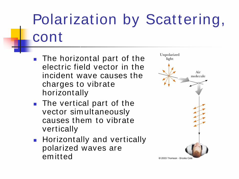
The horizontal part of the electric field vector in the incident wave causes the charges to vibrate horizontallyThe vertical part of the vector simultaneously causes them to vibrate verticallyHorizontally and vertically polarized waves are emitted

Optical Activity
Certain materials display the property of optical activity
A substance is optically active if it rotates the plane of polarization of transmitted lightOptical activity occurs in a material because of an asymmetry in the shape of its constituent materials
Liquid CrystalsA liquid crystal is a substance with properties intermediate between those of a crystalline solid and those of a liquid
The molecules of the substance are more orderly than those of a liquid but less than those in a pure crystalline solid
To create a display, the liquid crystal is placed between two glass plates and electrical contacts are made to the liquid crystal
A voltage is applied across any segment in the display and that segment turns on

Liquid Crystals, 2
Rotation of a polarized light beam by a liquid crystal when the applied voltage is zeroLight passes through the polarizer on the right and is reflected back to the observer, who sees the segment as being bright

Liquid Crystals, 3
When a voltage is applied, the liquid crystal does not rotate the plane of polarizationThe light is absorbed by the polarizer on the right and none is reflected back to the observerThe segment is dark

Liquid Crystals, final
Changing the applied voltage in a precise pattern can
Tick off the seconds on a watchDisplay a letter on a computer display