chapter 23 wood - mass.gov
TRANSCRIPT

1
CHAPTER 23 WOOD
User notes:
About this chapter: Chapter 23 provides minimum requirements for the design of buildings and structures that use wood and wood-based products. The chapter is organized around three design methodologies: allowable stress design (ASD), load and resistance factor design (LRFD) and conventional light-frame construction. In addition it allows the use of the American Wood Council Wood Frame Construction Manual for a limited range of structures. Included in the chapter are references to design and manufacturing standards for various wood and wood-based products; general construction requirements; design criteria for lateral force-resisting systems and specific requirements for the application of the three design methods.
Code development reminder: Code change proposals to this chapter will be considered by the IBC—Structural Code Development Committee during the 2022 (Group B) Code Development Cycle.
SECTION 2301
GENERAL 2301.1 Scope. The provisions of this chapter shall govern the materials, design, construction and quality of wood members and their fasteners. 2301.2 Nominal sizes. For the purposes of this chapter, where dimensions of lumber are specified, they shall be deemed to be nominal dimensions unless specifically designated as actual dimensions (see Section 2304.2).
SECTION 2302
DESIGN REQUIREMENTS 2302.1 General. The design of structural elements or systems, constructed partially or wholly of wood or wood-based products, shall be in accordance with one of the following methods:
1. Allowable stress design in accordance with Sections 2304, 2305 and 2306.
2. Load and resistance factor design in accordance with Sections 2304, 2305 and 2307.
3. Conventional light-frame construction in accordance with Sections 2304 and 2308.
4. AWC WFCM in accordance with Section 2309.
5. The design and construction of log structures in accordance with the provisions of ICC 400.
SECTION 2303
MINIMUM STANDARDS AND QUALITY 2303.1 General. Structural sawn lumber; end-jointed lumber; prefabricated wood I-joists; structural glued-laminated timber;
2
wood structural panels; fiberboard sheathing (where used structurally); hardboard siding (where used structurally); particleboard; preservative-treated wood; structural log members; structural composite lumber; round timber poles and piles; fire-retardant-treated wood; hardwood plywood; wood trusses; joist hangers; nails; and staples shall conform to the applicable provisions of this section.
2303.1.1 Sawn lumber. Sawn lumber used for load-supporting purposes, including end-jointed or edge-glued lumber, machine stress-rated or machine-evaluated lumber, shall be identified by the grade mark of a lumber grading or inspection agency that has been approved by an accreditation body that complies with DOC PS 20 or equivalent. Grading practices and identification shall comply with rules published by an agency approved in accordance with the procedures of DOC PS 20 or equivalent procedures.
2303.1.1.1 Certificate of inspection. In lieu of a grade mark on the material, a certificate of inspection as to species and grade issued by a lumber grading or inspection agency meeting the requirements of this section is permitted to be accepted for precut, remanufactured or rough-sawn lumber and for sizes larger than 3 inches (76 mm) nominal thickness.
2303.1.1.2 End-jointed lumber. Approved end-jointed lumber is permitted to be used interchangeably with solid-sawn members of the same species and grade. End-jointed lumber used in an assembly required to have a fire-resistance rating shall have the designation “Heat Resistant Adhesive” or “HRA” included in its grade mark.
2303.1.2 Prefabricated wood I-joists. Structural capacities and design provisions for prefabricated wood I-joists shall be established and monitored in accordance with ASTM D5055.
2303.1.3 Structural glued-laminated timber. Glued-laminated timbers shall be manufactured and identified as required in ANSI/APA 190.1 and ASTM D3737.
2303.1.4 Structural glued cross-laminated timber. Cross-laminated timbers shall be manufactured and identified in accordance with ANSI/APA PRG 320. 2303.1.5 Wood structural panels. Wood structural panels, where used structurally (including those used for siding, roof and wall sheathing, subflooring, diaphragms and built-up members), shall conform to the requirements for their type in DOC PS 1, DOC PS 2 or ANSI/APA PRP 210. Each panel or member shall be identified for grade, bond classification, and Performance Category by the trademarks of an approved testing and grading agency. The Performance Category value shall be used as the “nominal panel thickness” or “panel thickness” whenever referenced in this code. Wood structural panel components shall be designed and fabricated in accordance with the applicable standards listed in Section 2306.1 and identified by the trademarks of an approved testing and inspection agency indicating conformance to the applicable standard. In addition, wood structural panels where permanently exposed in outdoor applications shall be of exterior type, except that wood structural panel roof sheathing exposed to the outdoors on the underside is permitted to be Exposure 1 type.
2303.1.6 Fiberboard. Fiberboard for its various uses shall conform to ASTM C208. Fiberboard sheathing, where used structurally, shall be identified by an approved agency as conforming to ASTM C208.

3
2303.1.6.1 Jointing. To ensure tight-fitting assemblies, edges shall be manufactured with square, shiplapped, beveled, tongue-and-groove or U-shaped joints.
2303.1.6.2 Roof insulation. Where used as roof insulation in all types of construction, fiberboard shall be protected with an approved roof covering.
2303.1.6.3 Wall insulation. Where installed and fire-blocked to comply with Chapter 7, fiberboards are permitted as wall insulation in all types of construction. In fire walls and fire barriers, unless treated to comply with Section 803.1 for Class A materials, the boards shall be cemented directly to the concrete, masonry or other noncombustible base and shall be protected with an approved noncombustible veneer anchored to the base without intervening airspaces.
2303.1.6.3.1 Protection. Fiberboard wall insulation applied on the exterior of foundation walls shall be protected below ground level with a bituminous coating.
2303.1.7 Hardboard. Hardboard siding shall conform to the requirements of ANSI A135.6 and, where used structurally, shall be identified by the label of an approved agency. Hardboard underlayment shall meet the strength
requirements of 7/32
-inch (5.6 mm) or 1/4-inch (6.4 mm) service class hardboard planed or sanded on one
side to a uniform thickness of not less than 0.200 inch (5.1 mm). Prefinished hardboard paneling shall meet the requirements of ANSI A135.5. Other basic hardboard products shall meet the requirements of ANSI A135.4. Hardboard products shall be installed in accordance with manufacture’s recommendations. 2303.1.8 Particleboard. Particleboard shall conform to ANSI A208.1. Particleboard shall be identified by the grade mark or certificate of inspection issued by an approved agency. Particleboard shall not be utilized for applications other than indicated in this section unless the particleboard complies with the provisions of Section 2306.3.
2303.1.8.1 Floor underlayment. Particleboard floor underlayment shall conform to Type PBU of ANSI A208.1. Type PBU underlayment
shall be not less than 1/4-inch (6.4 mm) thick and shall be installed in accordance with the instructions of
the Composite Panel Association.
2303.1.9 Preservative-treated wood. Lumber, timber, plywood, piles and poles supporting permanent structures required by Section 2304.12 to be preservative treated shall conform to AWPA U1 and M4. Lumber and plywood used in permanent wood foundation systems shall conform to Chapter 18.
2303.1.9.1 Identification. Wood required by Section 2304.12 to be preservative treated shall bear the quality mark of an inspection agency that maintains continuing supervision, testing and inspection over the quality of the preservative-treated wood. Inspection agencies for preservative-treated wood shall be listed by an accreditation body that complies with the requirements of the American Lumber Standards Treated Wood Program, or equivalent. The quality mark shall be on a stamp or label affixed to the preservative-treated wood, and shall include the following information:
1. Identification of treating manufacturer.
4
2. Type of preservative used.
3. Minimum preservative retention (pcf).
4. End use for which the product is treated.
5. AWPA standard to which the product was treated.
6. Identity of the accredited inspection agency.
2303.1.9.2 Moisture content. Where preservative-treated wood is used in enclosed locations where drying in service cannot readily occur, such wood shall be at a moisture content of 19 percent or less before being covered with insulation, interior wall finish, floor covering or other materials.
2303.1.10 Structural composite lumber. Structural capacities for structural composite lumber shall be established and monitored in accordance with ASTM D5456. 2303.1.11 Structural log members. Stress grading of structural log members of nonrectangular shape, as typically used in log buildings, shall be in accordance with ASTM D3957. Such structural log members shall be identified by the grade mark of an approved lumber grading or inspection agency. In lieu of a grade mark on the material, a certificate of inspection as to species and grade issued by a lumber grading or inspection agency meeting the requirements of this section shall be permitted.
2303.1.12 Round timber poles and piles. Round timber poles and piles shall comply with ASTM D3200 and ASTM D25, respectively.
2303.1.13 Engineered wood rim board. Engineered wood rim boards shall conform to ANSI/APA PRR 410 or shall be evaluated in accordance with ASTM D7672. Structural capacities shall be in accordance with ANSI/APA PRR 410 or established in accordance with ASTM D7672. Rim boards conforming to ANSI/APA PRR 410 shall be marked in accordance with that standard.
2303.1.14 Native Lumber. Native lumber shall be acceptable for use in one- and two-family dwellings,
barns, sheds, and agricultural and accessory structures. Native lumber shall also be acceptable for use in
one- or two-story structures as columns when the design loads are 25% greater than required in 780 CMR
16.00; as joists, principal beams, and girders in floor constructions when the design loads are 15% greater
than required in 780 CMR 16.00; and as other elements when the design loads are as required in 780 CMR
16.00.
When native lumber is used, it shall be subject to the following requirements:
1. Sizing Criteria: For lumber, sized in accordance with the DOC PS-20, figures for maximum fiber
stress and modulus of elasticity for framing grade No. 2 shall be used in establishing span and
spacing characteristics for all structural members.
2. Stress Criteria: Lumber which is sized in excess of the dimensions established by the DOC PS-20
for the given nominal size referenced shall be allowed to have a maximum fiber stress increase
above that provided in section 2303.1.14 item 1 in proportion to the increased bearing capacity of
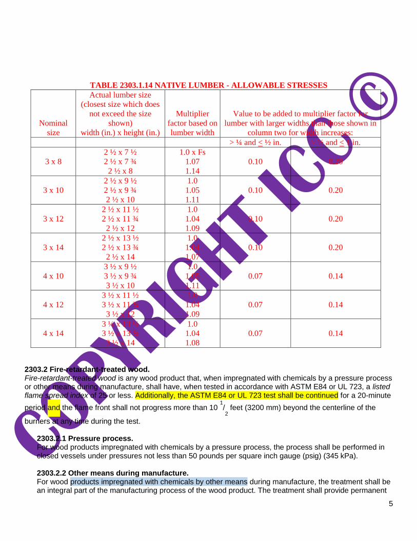
the cross section as provided in Table 2303.1.14.
5
TABLE 2303.1.14 NATIVE LUMBER - ALLOWABLE STRESSES
Nominal
size
Actual lumber size
(closest size which does
not exceed the size
shown)
width (in.) x height (in.)
Multiplier
factor based on
lumber width
Value to be added to multiplier factor for
lumber with larger widths than those shown in
column two for width increases:
> ¼ and < ½ in. > ½ and < 1 in.
3 x 8
2 ½ x 7 ½
2 ½ x 7 ¾
2 ½ x 8
1.0 x Fs
1.07
1.14
0.10 0.20
3 x 10
2 ½ x 9 ½
2 ½ x 9 ¾
2 ½ x 10
1.0
1.05
1.11
0.10 0.20
3 x 12
2 ½ x 11 ½
2 ½ x 11 ¾
2 ½ x 12
1.0
1.04
1.09
0.10 0.20
3 x 14
2 ½ x 13 ½
2 ½ x 13 ¾
2 ½ x 14
1.0
1.04
1.07
0.10 0.20
4 x 10
3 ½ x 9 ½
3 ½ x 9 ¾
3 ½ x 10
1.0
1.05
1.11
0.07 0.14
4 x 12
3 ½ x 11 ½
3 ½ x 11 ¾
3 ½ x 12
1.0
1.04
1.09
0.07 0.14
4 x 14
3 ½ x 13 ½
3 ½ x 13 ¾
3 ½ x 14
1.0
1.04
1.08
0.07 0.14
2303.2 Fire-retardant-treated wood. Fire-retardant-treated wood is any wood product that, when impregnated with chemicals by a pressure process or other means during manufacture, shall have, when tested in accordance with ASTM E84 or UL 723, a listed flame spread index of 25 or less. Additionally, the ASTM E84 or UL 723 test shall be continued for a 20-minute
period and the flame front shall not progress more than 10 1/2 feet (3200 mm) beyond the centerline of the
burners at any time during the test.
2303.2.1 Pressure process. For wood products impregnated with chemicals by a pressure process, the process shall be performed in closed vessels under pressures not less than 50 pounds per square inch gauge (psig) (345 kPa).
2303.2.2 Other means during manufacture. For wood products impregnated with chemicals by other means during manufacture, the treatment shall be an integral part of the manufacturing process of the wood product. The treatment shall provide permanent

6
protection to all surfaces of the wood product. The use of paints, coating, stains or other surface treatments is not an approved method of protection as required in this section.
2303.2.3 Fire testing of wood structural panels.
Wood structural panels shall be tested with a ripped or cut longitudinal gap of 1/8 inch (3.2 mm).
2303.2.4 Labeling. In addition to the labels required in Section 2303.1.1 for sawn lumber and Section 2303.1.5 for wood structural panels, each piece of fire-retardant-treated lumber and wood structural panels shall be labeled. The label shall contain the following items:
1. The identification mark of an approved agency in accordance with Section 1703.5.
2. Identification of the treating manufacturer.
3. The name of the fire-retardant treatment.
4. The species of wood treated.
5. Flame spread and smoke-developed index.
6. Method of drying after treatment.
7. Conformance with appropriate standards in accordance with Sections 2303.2.5 through 2303.2.8.
8. For fire-retardant-treated wood exposed to weather, damp or wet locations, include the words “No
increase in the listed classification when subjected to the Standard Rain Test” (ASTM D2898).
2303.2.5 Strength adjustments. Design values for untreated lumber and wood structural panels, as specified in Section 2303.1, shall be adjusted for fire-retardant-treated wood. Adjustments to design values shall be based on an approved method of investigation that takes into consideration the effects of the anticipated temperature and humidity to which the fire-retardant-treated wood will be subjected, the type of treatment and redrying procedures.
2303.2.5.1 Wood structural panels. The effect of treatment and the method of redrying after treatment, and exposure to high temperatures and high humidities on the flexure properties of fire-retardant-treated softwood plywood shall be determined in accordance with ASTM D5516. The test data developed by ASTM D5516 shall be used to develop adjustment factors, maximum loads and spans, or both, for untreated plywood design values in accordance with ASTM D6305. Each manufacturer shall publish the allowable maximum loads and spans for service as floor and roof sheathing for its treatment.
2303.2.5.2 Lumber. For each species of wood that is treated, the effects of the treatment, the method of redrying after treatment and exposure to high temperatures and high humidities on the allowable design properties of fire-retardant-treated lumber shall be determined in accordance with ASTM D5664. The test data developed by ASTM D5664 shall be used to develop modification factors for use at or near room temperature and at elevated temperatures and humidity in accordance with ASTM D6841. Each manufacturer shall publish the modification factors for service at temperatures of not less than 80°F (27°C) and for roof framing. The roof framing modification factors shall take into consideration the climatological location.

7
2303.2.6 Exposure to weather, damp or wet locations. Where fire-retardant-treated wood is exposed to weather, or damp or wet locations, it shall be identified as “Exterior” to indicate there is no increase in the listed flame spread index as defined in Section 2303.2 when subjected to ASTM D2898. 2303.2.7 Interior applications. Interior fire-retardant-treated wood shall have moisture content of not over 28 percent when tested in accordance with ASTM D3201 procedures at 92-percent relative humidity. Interior fire-retardant-treated wood shall be tested in accordance with Section 2303.2.5.1 or 2303.2.5.2. Interior fire-retardant-treated wood designated as Type A shall be tested in accordance with the provisions of this section.
2303.2.8 Moisture content. Fire-retardant-treated wood shall be dried to a moisture content of 19 percent or less for lumber and 15 percent or less for wood structural panels before use. For wood kiln-dried after treatment (KDAT), the kiln temperatures shall not exceed those used in kiln drying the lumber and plywood submitted for the tests described in Section 2303.2.5.1 for plywood and 2303.2.5.2 for lumber.
2303.2.9 Types I and II construction applications. See Section 603.1 for limitations on the use of fire-retardant-treated wood in buildings of Type I or II construction.
2303.3 Hardwood and plywood. Hardwood and decorative plywood shall be manufactured and identified as required in HPVA HP-1. 2303.4 Trusses. Wood trusses shall comply with Sections 2303.4.1 through 2303.4.7.
2303.4.1 Design. Wood trusses shall be designed in accordance with the provisions of this code and accepted engineering practice. Members are permitted to be joined by nails, glue, bolts, timber connectors, metal connector plates or other approved framing devices.
2303.4.1.1 Truss design drawings. The written, graphic and pictorial depiction of each individual truss shall be provided to the building official for approval prior to installation. Truss design drawings shall be provided with the shipment of trusses delivered to the job site. Truss design drawings shall include, at a minimum, the following information:
1. Slope or depth, span and spacing.
2. Location of all joints and support locations.
3. Number of plies if greater than one.
4. Required bearing widths.
5. Design loads as applicable, including:
5.1. Top chord live load.
5.2. Top chord dead load.
5.3. Bottom chord live load.

8
5.4. Bottom chord dead load.
5.5. Additional loads and locations.
5.6. Environmental design criteria and loads (such as wind, rain, snow, seismic).
6. Other lateral loads, including drag strut loads.
7. Adjustments to wood member and metal connector plate design value for conditions of use. 8. Maximum reaction force and direction, including maximum uplift reaction forces where
applicable. 9. Joint connection type and description, such as size and thickness or gage, and the dimensioned
location of each joint connector except where symmetrically located relative to the joint interface. 10. Size, species and grade for each wood member. 11. Truss-to-truss connections and truss field assembly requirements. 12. Calculated span-to-deflection ratio and maximum vertical and horizontal deflection for live and
total load as applicable. 13. Maximum axial tension and compression forces in the truss members. 14. Required permanent individual truss member restraint location and the method and details of
restraint and diagonal bracing to be used in accordance with Section 2303.4.1.2.
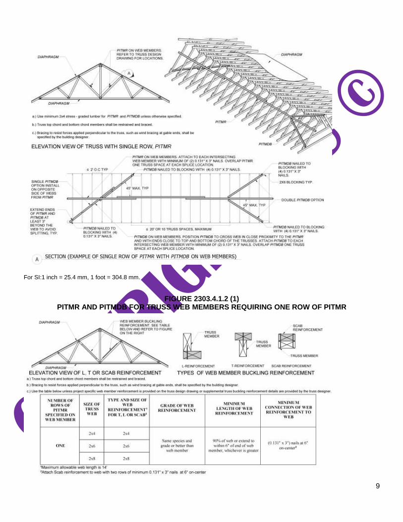
2303.4.1.2 Permanent individual truss member restraint (PITMR) and permanent individual truss member diagonal bracing (PITMDB). Where the truss design drawings designate the need for permanent individual truss member restraint, it shall be accomplished by one of the following methods:
1. PITMR and PITMDB installed using standard industry lateral restraint and diagonal bracing
details in accordance with TPI 1, Section 2.3.3.1.1, accepted engineering practice, or Figures 2303.4.1.2(1), (3), and (5).
2. Individual truss member reinforcement in place of the specified lateral restraints (i.e., buckling
reinforcement such as T-reinforcement, L-reinforcement, proprietary reinforcement, etc.) such that the buckling of any individual truss member is resisted internally by the individual truss. The buckling reinforcement of individual truss members shall be installed as shown on the truss design drawing, on supplemental truss member buckling reinforcement details provided by the truss designer or in accordance with Figures 2303.4.1.2 (2) and (4).
3. A project-specific PITMR and PITMDB design provided by any registered design professional.
9
For SI:1 inch = 25.4 mm, 1 foot = 304.8 mm.
FIGURE 2303.4.1.2 (1) PITMR AND PITMDB FOR TRUSS WEB MEMBERS REQUIRING ONE ROW OF PITMR

10
For SI:1 inch - 25.4 mm, 1 foot = 304.8 mm.
FIGURE 2303.4.1.2(2) ALTERNATIVE INSTALLATION USING BUCKLING REINFORCEMENT FOR TRUSS WEB MEMBERS IN
LIEU OF ONE ROW OF PITMR
For SI:1 inch = 25.4 mm, 1 foot = 304.8 mm.
FIGURE 2303.4.1.2(3) PITMR AND PITMDB FOR TRUSS WEB MEMBERS REQUIRING TWO ROWS OF PITMR

11
For SI:1 inch = 25.4 mm, 1 foot = 304.8 mm.
FIGURE 2303.4.1.2(4) ALTERNATIVE INSTALLATION USING BUCKLING REINFORCEMENT FOR TRUSS WEB MEMBERS IN
LIEU OF TWO ROWS OF PITMR

12
For SI:1 inch = 25.4 mm, 1 foot = 304.8 mm.
FIGURE 2303.4.1.2(5) PITMR AND PITMDB FOR FLAT PORTION OF TOP CHORD IN A PIGGYBACK ASSEMBLY
13
2303.4.1.2.1 Trusses installed without a diaphragm. Trusses installed without a diaphragm on the top or bottom chord shall require a project specific PITMR and PITMDB design prepared by a registered design professional.
Exception: Group U occupancies.
2303.4.1.3 Trusses spanning 60 feet or greater. The owner or the owner’s authorized agent shall contract with any qualified registered design professional for the design of the temporary installation restraint and diagonal bracing and the PITMR and PITMDB for all trusses with clear spans 60 feet (18 288 mm) or greater.
2303.4.1.4 Truss designer. The individual or organization responsible for the design of trusses.
2303.4.1.4.1 Truss design drawings. Where required by the registered design professional, the building official or the statutes of the jurisdiction in which the project is to be constructed, each individual truss design drawing shall bear the seal and signature of the truss designer.
Exceptions:
1. Where a cover sheet and truss index sheet are combined into a single sheet and
attached to the set of truss design drawings, the single cover/truss index sheet is the only document required to be signed and sealed by the truss designer.
2. Where a cover sheet and a truss index sheet are separately provided and attached to
the set of truss design drawings, the cover sheet and the truss index sheet are the only documents required to be signed and sealed by the truss designer.
2303.4.2 Truss placement diagram. The truss manufacturer shall provide a truss placement diagram that identifies the proposed location for each individually designated truss and references the corresponding truss design drawing. The truss placement diagram shall be provided as part of the truss submittal package, and with the shipment of trusses delivered to the job site. Truss placement diagrams that serve only as a guide for installation and do not deviate from the permit submittal drawings shall not be required to bear the seal or signature of the truss designer.
2303.4.3 Truss submittal package. The truss submittal package provided by the truss manufacturer shall consist of each individual truss design drawing, the truss placement diagram, the permanent individual truss member restraint/bracing method and details and any other structural details germane to the trusses; and, as applicable, the cover/truss index sheet.
2303.4.4 Anchorage. The design for the transfer of loads and anchorage of each truss to the supporting structure is the responsibility of the registered design professional.
2303.4.5 Alterations to trusses. Truss members and components shall not be cut, notched, drilled, spliced or otherwise altered in any way without written concurrence and approval of a registered design professional. Alterations resulting in the addition of loads to any member (for example, HVAC equipment, piping, additional roofing or insulation) shall not be permitted without verification that the truss is capable of supporting such additional loading.
14
2303.4.6 TPI 1 specifications. In addition to Sections 2303.4.1 through 2303.4.5, the design, manufacture and quality assurance of metal-plate-connected wood trusses shall be in accordance with TPI 1. Job-site inspections shall be in compliance with Section 110.4, as applicable.
2303.4.7 Truss quality assurance. Trusses not part of a manufacturing process in accordance with either Section 2303.4.6 or a referenced standard, which provides requirements for quality control done under the supervision of a third-party quality control agency, shall be manufactured in compliance with Sections 1704.2.5 and 1705.5, as applicable.
2303.5 Test standard for joist hangers. Joist hangers shall be in accordance with ASTM D7147. 2303.6 Nails and staples. Nails and staples shall conform to requirements of ASTM F1667, including Supplement 1. Nails used for framing and sheathing connections shall have minimum average bending yield strengths as follows: 80 kips per square inch (ksi) (551 MPa) for shank diameters larger than 0.177 inch (4.50 mm) but not larger than 0.254 inch (6.45 mm), 90 ksi (620 MPa) for shank diameters larger than 0.142 inch (3.61 mm) but not larger than 0.177 inch (4.50 mm) and 100 ksi (689 MPa) for shank diameters of not less than 0.099 inch (2.51 mm) but not larger than 0.142 inch (3.61 mm). Staples used for framing and sheathing connections shall have minimum average bending moments as follows: 3.6 in.-lbs (0.41 N-m) for No. 16 gage staples, 4.0 in.-lbs (0.45 N-m) for No. 15 gage staples, and 4.3 in.-lbs (0.49 N-m) for No. 14 gage staples. 2303.7 Shrinkage. Consideration shall be given in design for the effects of wood cross-grain dimensional changes that occur as a result of changes in the wood moisture content after installation.
SECTION 2304
GENERAL CONSTRUCTION REQUIREMENTS 2304.1 General. The provisions of this section apply to design methods specified in Section 2302.1. 2304.2 Size of structural members. Computations to determine the required sizes of members shall be based on the net dimensions (actual sizes) and not nominal sizes. 2304.3 Wall framing. The framing of exterior and interior walls shall be in accordance with the provisions specified in Section 2308 unless a specific design is furnished.
2304.3.1 Bottom plates.
Studs shall have full bearing on a 2-inch-thick (actual 11/2-inch, 38 mm) or larger plate or sill having a width
not less than equal to the width of the studs.
2304.3.2 Framing over openings. Headers, double joists, trusses or other approved assemblies that are of adequate size to transfer loads to the vertical members shall be provided over window and door openings in load-bearing walls and partitions.
2304.3.3 Shrinkage. Wood walls and bearing partitions shall not support more than two floors and a roof unless an analysis

15
satisfactory to the building official shows that shrinkage of the wood framing will not have adverse effects on the structure or any plumbing, electrical or mechanical systems or other equipment installed therein due to excessive shrinkage or differential movements caused by shrinkage. The analysis shall show that the roof drainage system and the foregoing systems or equipment will not be adversely affected or, as an alternate, such systems shall be designed to accommodate the differential shrinkage or movements.
2304.4 Floor and roof framing. The framing of wood-joisted floors and wood-framed roofs shall be in accordance with the provisions specified in Section 2308 unless a specific design is furnished. 2304.5 Framing around flues and chimneys. Combustible framing shall be not less than 2 inches (51 mm), but shall be not less than the distance specified in Sections 2111 and 2113 and the International Mechanical Code, from flues, chimneys and fireplaces, and 6 inches (152 mm) away from flue openings. 2304.6 Exterior wall sheathing. Wall sheathing on the outside of exterior walls, including gables, and the connection of the sheathing to framing shall be designed in accordance with the general provisions of this code and shall be capable of resisting wind pressures in accordance with Section 1609.
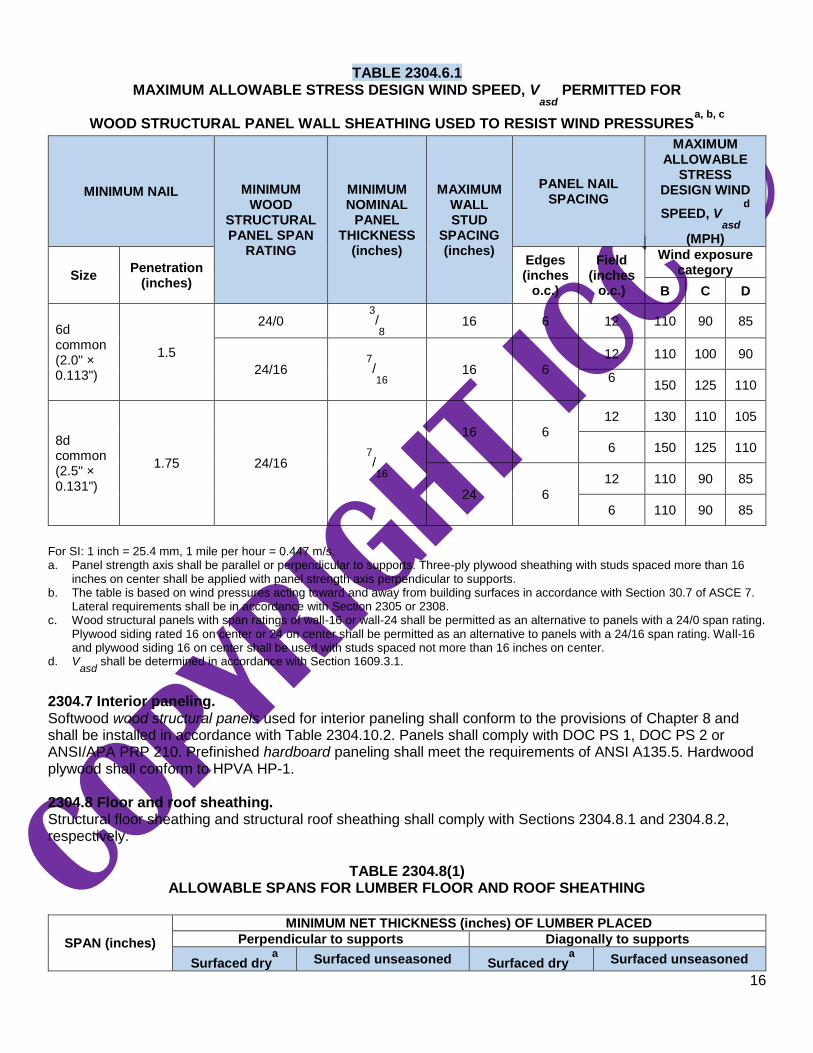
2304.6.1 Wood structural panel sheathing. Where wood structural panel sheathing is used as the exposed finish on the outside of exterior walls, it shall have an exterior exposure durability classification. Where wood structural panel sheathing is used elsewhere, but not as the exposed finish, it shall be of a type manufactured with exterior glue (Exposure 1 or Exterior). Wood structural panel sheathing, connections and framing spacing shall be in accordance with Table 2304.6.1 for the applicable wind speed and exposure category where used in enclosed buildings with a mean roof height not greater than 30 feet (9144 mm) and a topographic factor (K
z t) of 1.0.
16
TABLE 2304.6.1 MAXIMUM ALLOWABLE STRESS DESIGN WIND SPEED, V
asd PERMITTED FOR
WOOD STRUCTURAL PANEL WALL SHEATHING USED TO RESIST WIND PRESSURESa, b, c
MINIMUM NAIL MINIMUM WOOD
STRUCTURAL PANEL SPAN
RATING
MINIMUM NOMINAL
PANEL THICKNESS
(inches)
MAXIMUM WALL STUD
SPACING (inches)
PANEL NAIL SPACING
MAXIMUM ALLOWABLE
STRESS DESIGN WIND
SPEED, Vasd
d
(MPH)
Size Penetration
(inches)
Edges (inches
o.c.)
Field (inches
o.c.)
Wind exposure category
B C D
6d common (2.0" × 0.113")
1.5
24/0 3/8 16 6 12 110 90 85
24/16 7/16
16 6
12 110 100 90
6 150 125 110
8d common (2.5" × 0.131")
1.75 24/16 7/16
16 6 12 130 110 105
6 150 125 110
24 6
12 110 90 85
6 110 90 85
For SI: 1 inch = 25.4 mm, 1 mile per hour = 0.447 m/s. a. Panel strength axis shall be parallel or perpendicular to supports. Three-ply plywood sheathing with studs spaced more than 16
inches on center shall be applied with panel strength axis perpendicular to supports. b. The table is based on wind pressures acting toward and away from building surfaces in accordance with Section 30.7 of ASCE 7.
Lateral requirements shall be in accordance with Section 2305 or 2308. c. Wood structural panels with span ratings of wall-16 or wall-24 shall be permitted as an alternative to panels with a 24/0 span rating.
Plywood siding rated 16 on center or 24 on center shall be permitted as an alternative to panels with a 24/16 span rating. Wall-16 and plywood siding 16 on center shall be used with studs spaced not more than 16 inches on center.
d. Vasd
shall be determined in accordance with Section 1609.3.1.
2304.7 Interior paneling. Softwood wood structural panels used for interior paneling shall conform to the provisions of Chapter 8 and shall be installed in accordance with Table 2304.10.2. Panels shall comply with DOC PS 1, DOC PS 2 or ANSI/APA PRP 210. Prefinished hardboard paneling shall meet the requirements of ANSI A135.5. Hardwood plywood shall conform to HPVA HP-1. 2304.8 Floor and roof sheathing. Structural floor sheathing and structural roof sheathing shall comply with Sections 2304.8.1 and 2304.8.2, respectively.
TABLE 2304.8(1)
ALLOWABLE SPANS FOR LUMBER FLOOR AND ROOF SHEATHING
SPAN (inches)
MINIMUM NET THICKNESS (inches) OF LUMBER PLACED
Perpendicular to supports Diagonally to supports
Surfaced drya Surfaced unseasoned Surfaced dry
a Surfaced unseasoned

17
Floors
24 3/4
25/32
3/4
25/32
16 5/8
11/16
5/8
11/16
Roofs
24 5/8
11/16
3/4
25/32
For SI: 1 inch = 25.4 mm. a. Maximum 19-percent moisture content.
TABLE 2304.8(2)
SHEATHING LUMBER, MINIMUM GRADE REQUIREMENTS: BOARD GRADE
SOLID FLOOR OR ROOF SHEATHING SPACED ROOF
SHEATHING GRADING RULES
Utility Standard NLGA, WCLIB, WWPA
4 common or utility 3 common or standard NLGA, WCLIB, WWPA, NSLB or NELMA
No. 3 No. 2 SPIB
Merchantable Construction common RIS
18
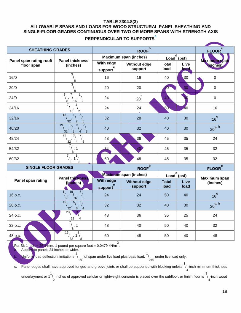
TABLE 2304.8(3) ALLOWABLE SPANS AND LOADS FOR WOOD STRUCTURAL PANEL SHEATHING AND
SINGLE-FLOOR GRADES CONTINUOUS OVER TWO OR MORE SPANS WITH STRENGTH AXIS
PERPENDICULAR TO SUPPORTSa
SHEATHING GRADES ROOFb FLOOR
c
Panel span rating roof/ floor span
Panel thickness (inches)
Maximum span (inches) Loadd
(psf) Maximum span
(inches) With edge
supporte
Without edge support
Total load
Live load
16/0 3/8 16 16 40 30 0
20/0 3/8 20 20 40 30 0
24/0 3/8,
7/16
, 1/2 24 20
f 40 30 0
24/16 7/16
, 1/2 24 24 50 40 16
32/16 15
/32
, 1/2,
5/8 32 28 40 30 16
g
40/20 19
/32
, 5/8, 3
/4, 7
/8 40 32 40 30 20
g, h
48/24 23
/32
,
3/4,
7/8 48 36 45 35 24
54/32 7/8, 1 54 40 45 35 32
60/32 7/8, 1
1/8 60 48 45 35 32
SINGLE FLOOR GRADES ROOFb FLOOR
c
Panel span rating Panel thickness
(inches)
Maximum span (inches) Loade
(psf) Maximum span
(inches) With edge
supporte
Without edge support
Total load
Live load
16 o.c. 1/2,
19/32
, 5/8 24 24 50 40 16
g
20 o.c. 19
/32
, 5/8, 3
/4 32 32 40 30 20
g, h
24 o.c. 23
/32
,
3/4 48 36 35 25 24
32 o.c. 7/8, 1 48 40 50 40 32
48 o.c. 13
/32
, 11/8 60 48 50 40 48
For SI: 1 inch = 25.4 mm, 1 pound per square foot = 0.0479 kN/m2.
a. Applies to panels 24 inches or wider.
b. Uniform load deflection limitations 1/180
of span under live load plus dead load, 1/240
under live load only.
c. Panel edges shall have approved tongue-and-groove joints or shall be supported with blocking unless 1/4-inch minimum thickness
underlayment or 11/2 inches of approved cellular or lightweight concrete is placed over the subfloor, or finish floor is
3/4-inch wood
19
strip. Allowable uniform load based on deflection of 1/360
of span is 100 pounds per square foot except the span rating of 48 inches
on center is based on a total load of 65 pounds per square foot. d. Allowable load at maximum span. e. Tongue-and-groove edges, panel edge clips (one midway between each support, except two equally spaced between supports 48
inches on center), lumber blocking or other. Only lumber blocking shall satisfy blocked diaphragm requirements.
f. For 1/2-inch panel, maximum span shall be 24 inches.
g. Span is permitted to be 24 inches on center where 3/4-inch wood strip flooring is installed at right angles to joist.
h. Span is permitted to be 24 inches on center for floors where 11/2 inches of cellular or lightweight concrete is applied over the
panels.
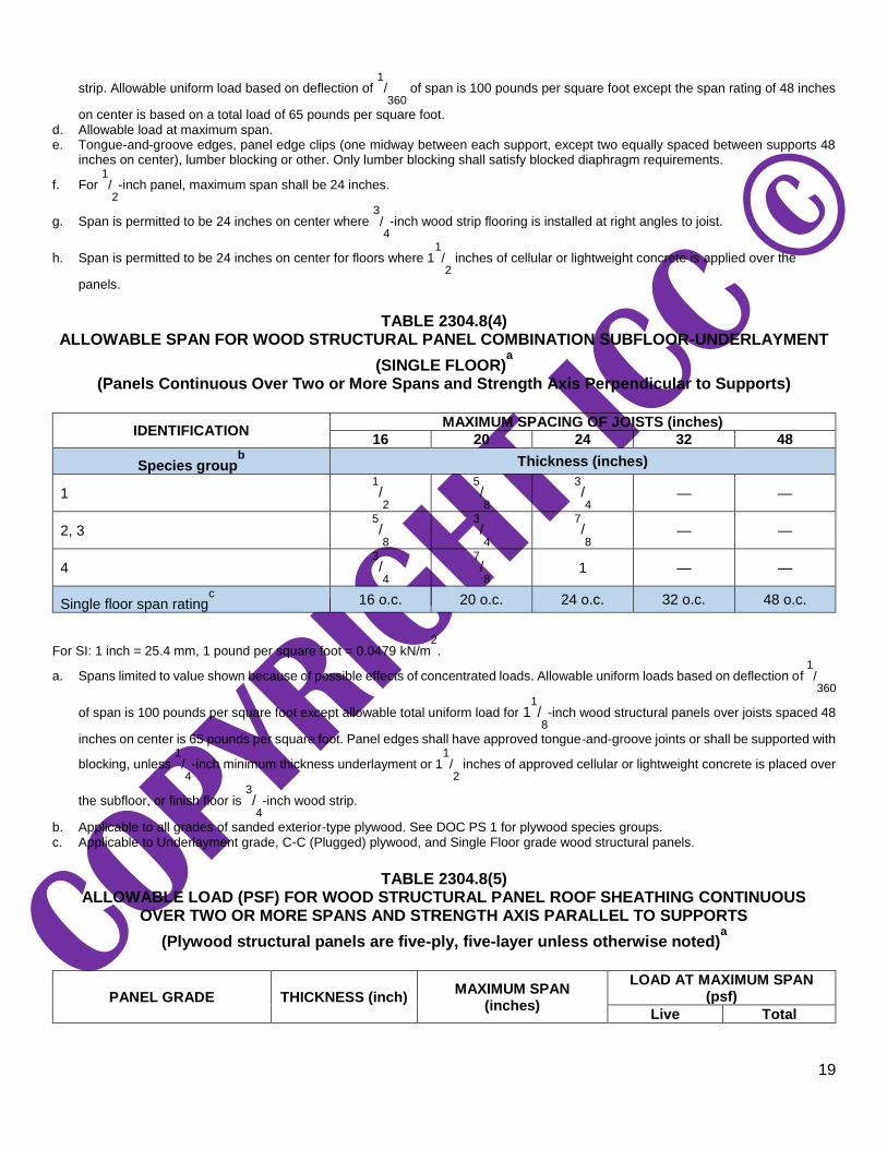
TABLE 2304.8(4)
ALLOWABLE SPAN FOR WOOD STRUCTURAL PANEL COMBINATION SUBFLOOR-UNDERLAYMENT
(SINGLE FLOOR)a
(Panels Continuous Over Two or More Spans and Strength Axis Perpendicular to Supports)
IDENTIFICATION MAXIMUM SPACING OF JOISTS (inches)
16 20 24 32 48
Species groupb Thickness (inches)
1 1/2
5/8
3/4 — —
2, 3 5/8
3/4
7/8 — —
4 3/4
7/8 1 — —
Single floor span ratingc 16 o.c. 20 o.c. 24 o.c. 32 o.c. 48 o.c.
For SI: 1 inch = 25.4 mm, 1 pound per square foot = 0.0479 kN/m2.
a. Spans limited to value shown because of possible effects of concentrated loads. Allowable uniform loads based on deflection of 1/360
of span is 100 pounds per square foot except allowable total uniform load for 11/8-inch wood structural panels over joists spaced 48
inches on center is 65 pounds per square foot. Panel edges shall have approved tongue-and-groove joints or shall be supported with
blocking, unless 1/4-inch minimum thickness underlayment or 1
1/2 inches of approved cellular or lightweight concrete is placed over
the subfloor, or finish floor is 3/4-inch wood strip.
b. Applicable to all grades of sanded exterior-type plywood. See DOC PS 1 for plywood species groups. c. Applicable to Underlayment grade, C-C (Plugged) plywood, and Single Floor grade wood structural panels.
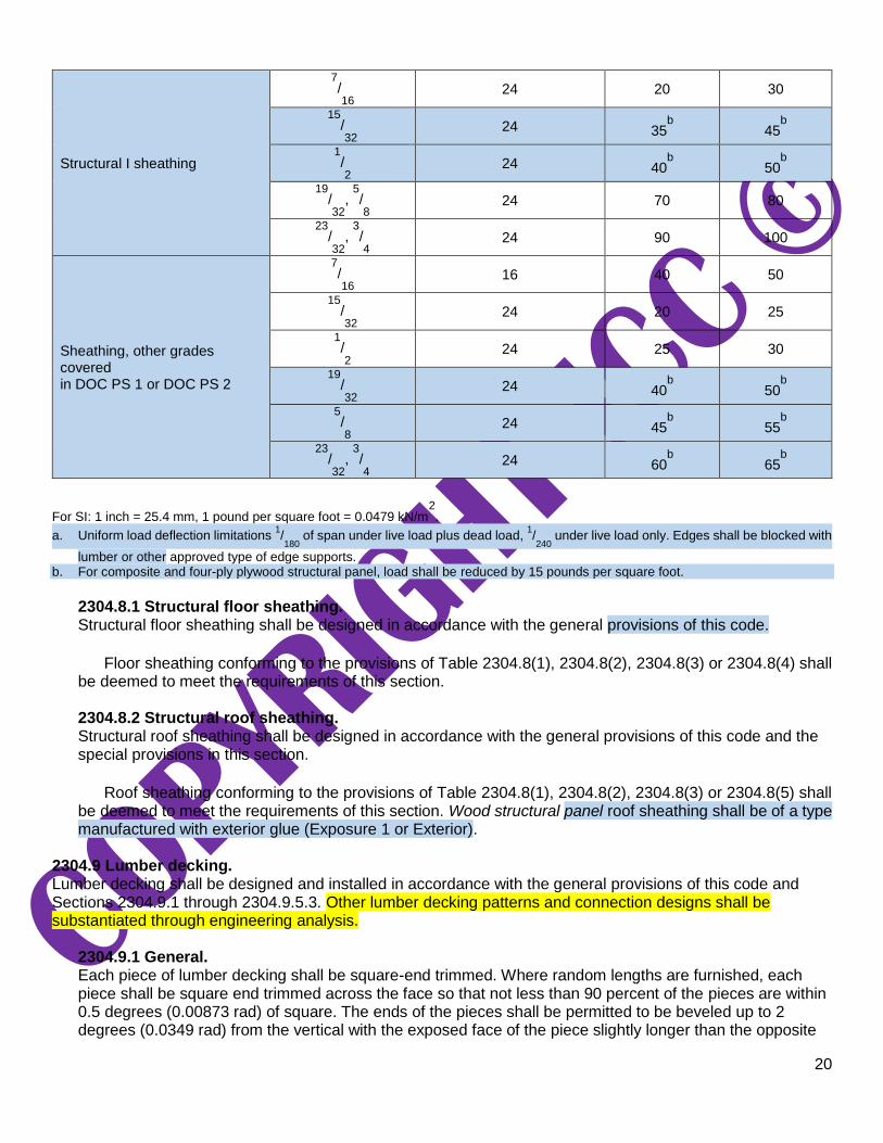
TABLE 2304.8(5)
ALLOWABLE LOAD (PSF) FOR WOOD STRUCTURAL PANEL ROOF SHEATHING CONTINUOUS OVER TWO OR MORE SPANS AND STRENGTH AXIS PARALLEL TO SUPPORTS
(Plywood structural panels are five-ply, five-layer unless otherwise noted)a
PANEL GRADE THICKNESS (inch) MAXIMUM SPAN
(inches)
LOAD AT MAXIMUM SPAN (psf)
Live Total
20
Structural I sheathing
7/16
24 20 30
15/32
24 35b 45
b
1/2 24 40
b 50
b
19/32
, 5/8 24 70 80
23/32
, 3/4 24 90 100
Sheathing, other grades covered in DOC PS 1 or DOC PS 2
7/16
16 40 50
15/32
24 20 25
1/2 24 25 30
19/32
24 40b 50
b
5/8 24 45
b 55
b
23/32
, 3/4 24 60
b 65
b
For SI: 1 inch = 25.4 mm, 1 pound per square foot = 0.0479 kN/m2.
a. Uniform load deflection limitations 1/180
of span under live load plus dead load, 1/240
under live load only. Edges shall be blocked with
lumber or other approved type of edge supports. b. For composite and four-ply plywood structural panel, load shall be reduced by 15 pounds per square foot.
2304.8.1 Structural floor sheathing. Structural floor sheathing shall be designed in accordance with the general provisions of this code.
Floor sheathing conforming to the provisions of Table 2304.8(1), 2304.8(2), 2304.8(3) or 2304.8(4) shall
be deemed to meet the requirements of this section.
2304.8.2 Structural roof sheathing. Structural roof sheathing shall be designed in accordance with the general provisions of this code and the special provisions in this section.
Roof sheathing conforming to the provisions of Table 2304.8(1), 2304.8(2), 2304.8(3) or 2304.8(5) shall
be deemed to meet the requirements of this section. Wood structural panel roof sheathing shall be of a type manufactured with exterior glue (Exposure 1 or Exterior).
2304.9 Lumber decking. Lumber decking shall be designed and installed in accordance with the general provisions of this code and Sections 2304.9.1 through 2304.9.5.3. Other lumber decking patterns and connection designs shall be substantiated through engineering analysis.
2304.9.1 General. Each piece of lumber decking shall be square-end trimmed. Where random lengths are furnished, each piece shall be square end trimmed across the face so that not less than 90 percent of the pieces are within 0.5 degrees (0.00873 rad) of square. The ends of the pieces shall be permitted to be beveled up to 2 degrees (0.0349 rad) from the vertical with the exposed face of the piece slightly longer than the opposite

21
face of the piece. Tongue-and-groove decking shall be installed with the tongues up on sloped or pitched roofs with pattern faces down.
2304.9.2 Layup patterns. Lumber decking is permitted to be laid up following one of five standard patterns as defined in Sections 2304.9.2.1 through 2304.9.2.5.
2304.9.2.1 Simple span pattern. All pieces shall be supported on their ends (in other words, by two supports).
2304.9.2.2 Two-span continuous pattern. All pieces shall be supported by three supports, and all end joints shall occur in line on alternating supports. Supporting members shall be designed to accommodate the load redistribution caused by this pattern.
2304.9.2.3 Combination simple and two-span continuous pattern. Courses in end spans shall be alternating simple-span pattern and two-span continuous pattern. End joints shall be staggered in adjacent courses and shall bear on supports.
2304.9.2.4 Cantilevered pieces intermixed pattern. The decking shall extend across not fewer than three spans. Pieces in each starter course and every third course shall be simple span pattern. Pieces in other courses shall be cantilevered over the supports with end joints at alternating quarter or third points of the spans. Each piece shall bear on one support or more.
2304.9.2.5 Controlled random pattern. The decking shall extend across not fewer than three spans. End joints of pieces within 6 inches (152 mm) of the end joints of the adjacent pieces in either direction shall be separated by not fewer than two intervening courses. In the end bays, each piece shall bear on one support or more. Where an end joint occurs in an end bay, the next piece in the same course shall continue over the first inner support for not less than 24 inches (610 mm). The details of the controlled random pattern shall be as specified for each decking material in Section 2304.9.3.3, 2304.9.4.3 or 2304.9.5.3.
Decking that cantilevers beyond a support for a horizontal distance greater than 18 inches (457 mm),
24 inches (610 mm) or 36 inches (914 mm) for 2-inch (51 mm), 3-inch (76 mm) and 4-inch (102 mm) nominal thickness decking, respectively, shall comply with the following:
1. The maximum cantilevered length shall be 30 percent of the length of the first adjacent interior
span.
2. A structural fascia shall be fastened to each decking piece to maintain a continuous, straight line.
3. End joints shall not be in the decking between the cantilevered end of the decking and the
centerline of the first adjacent interior span.
2304.9.3 Mechanically laminated decking. Mechanically laminated decking shall comply with Sections 2304.9.3.1 through 2304.9.3.3.
2304.9.3.1 General. Mechanically laminated decking consists of square-edged dimension lumber laminations set on edge and nailed to the adjacent pieces and to the supports.

22
2304.9.3.2 Nailing. The length of nails connecting laminations shall be not less than two and one-half times the net thickness of each lamination. Where decking supports are 48 inches (1219 mm) on center or less, side nails shall be installed not more than 30 inches (762 mm) on center alternating between top and bottom edges, and staggered one-third of the spacing in adjacent laminations. Where supports are spaced more than 48 inches (1219 mm) on center, side nails shall be installed not more than 18 inches (457 mm) on center alternating between top and bottom edges and staggered one-third of the spacing in adjacent laminations. For mechanically laminated decking constructed with laminations of 2-inch (51 mm) nominal thickness, nailing in accordance with Table 2304.9.3.2 shall be permitted. Two side nails shall be installed at each end of butt-jointed pieces.
Laminations shall be toenailed to supports with 20d or larger common nails. Where the supports are
48 inches (1219 mm) on center or less, alternate laminations shall be toenailed to alternate supports; where supports are spaced more than 48 inches (1219 mm) on center, alternate laminations shall be toenailed to every support. For mechanically laminated decking constructed with laminations of 2-inch (51 mm) nominal thickness, toenailing in accordance with Table 2304.9.3.2 shall be permitted.
TABLE 2304.9.3.2 FASTENING SCHEDULE FOR MECHANICALLY LAMINATED DECKING USING LAMINATIONS OF 2-
INCH NOMINAL THICKNESS
MINIMUM NAIL SIZE (Length x Diameter)
(inches)
MAXIMUM SPACING BETWEEN FACE NAILS a, b
(inches)
NUMBER OF TOENAILS
INTO SUPPORTSc Decking Supports ≤ 48
inches o.c. Decking Supports
> 48 inches o.c.
4 × 0.192 30 18 1
4 × 0.162 24 14 2
4 × 0.148 22 13 2
31/2 × 0.162 20 12 2
31/2 × 0.148 19 11 2
31/2 × 0.135 17 10 2
3 × 0.148 11 7 2
3 × 0.128 9 5 2
23/4 × 0.148 10 6 2
23/4 × 0.131 9 6 3
23/4 × 0.120 8 5 3
For SI: 1 inch = 25.4 mm a. Nails shall be driven perpendicular to the lamination face, alternating between top and bottom edges. b. Where nails penetrate through two laminations and into the third, they shall be staggered one-third of the spacing in adjacent
laminations. Otherwise, nails shall be staggered one-half of the spacing in adjacent laminations. c. Where supports are 48 inches on center or less, alternate laminations shall be toenailed to alternate supports; where supports are
spaced more than 48 inches on center, alternate laminations shall be toenailed to every support.
2304.9.3.3 Controlled random pattern. There shall be a minimum distance of 24 inches (610 mm) between end joints in adjacent courses. The pieces in the first and second courses shall bear on not fewer than two supports with end joints in these

23
two courses occurring on alternate supports. Not more than seven intervening courses shall be permitted before this pattern is repeated.
2304.9.4 Two-inch sawn tongue-and-groove decking. Two-inch (51 mm) sawn tongue-and-groove decking shall comply with Sections 2304.9.4.1 through 2304.9.4.3.
2304.9.4.1 General. Two-inch (51 mm) decking shall have a maximum moisture content of 15 percent. Decking shall be machined with a single tongue-and-groove pattern. Each decking piece shall be nailed to each support.
2304.9.4.2 Nailing. Each piece of decking shall be toenailed at each support with one 16d common nail through the tongue and face-nailed with one 16d common nail.
2304.9.4.3 Controlled random pattern. There shall be a minimum distance of 24 inches (610 mm) between end joints in adjacent courses. The pieces in the first and second courses shall bear on not fewer than two supports with end joints in these two courses occurring on alternate supports. Not more than seven intervening courses shall be permitted before this pattern is repeated.
2304.9.5 Three- and four-inch sawn tongue-and-groove decking. Three- and four-inch (76 mm and 102 mm) sawn tongue-and-groove decking shall comply with Sections 2304.9.5.1 through 2304.9.5.3.
2304.9.5.1 General. Three-inch (76 mm) and four-inch (102 mm) decking shall have a maximum moisture content of 19 percent. Decking shall be machined with a double tongue-and-groove pattern. Decking pieces shall be interconnected and nailed to the supports.
2304.9.5.2 Nailing. Each piece shall be toenailed at each support with one 40d common nail and face-nailed with one 60d common nail. Courses shall be spiked to each other with 8-inch (203 mm) spikes at maximum intervals of 30 inches (762 mm) through predrilled edge holes penetrating to a depth of approximately 4 inches (102 mm). One spike shall be installed at a distance not exceeding 10 inches (254 mm) from the end of each piece.
2304.9.5.3 Controlled random pattern. There shall be a minimum distance of 48 inches (1219 mm) between end joints in adjacent courses. Pieces not bearing on a support are permitted to be located in interior bays provided that the adjacent pieces in the same course continue over the support for not less than 24 inches (610 mm). This condition shall not occur more than once in every six courses in each interior bay.
2304.10 Connectors and fasteners. Connectors and fasteners shall comply with the applicable provisions of Sections 2304.10.1 through 2304.10.8 .
2304.10.1 Connection fire-resistance rating. Fire-resistance ratings for connections in Type IV-A, IV-B, or IV-C construction shall be determined by one of the following:
1. Testing in accordance with Section 703.2 where the connection is part of the fire resistance test.

24
2. Engineering analysis that demonstrates that the temperature rise at any portion of the connection is limited to an average temperature rise of 250°F (139°C), and a maximum temperature rise of 325°F (181°C), for a time corresponding to the required fire-resistance rating of the structural element being connected. For the purposes of this analysis, the connection includes connectors, fasteners, and portions of wood members included in the structural design of the connection.
2304.10.2 Fastener requirements. Connections for wood members shall be designed in accordance with the appropriate methodology in Section 2302.1. The number and size of fasteners connecting wood members shall be not less than that set forth in Table 2304.10.2.
TABLE 2304.10.2 FASTENING SCHEDULE
DESCRIPTION OF BUILDING ELEMENTS NUMBER AND TYPE OF FASTENERg SPACING AND LOCATION
Roof
1. Blocking between ceiling joists, rafters or trusses to top plate or other framing below
4-8d box (21/ ″ x 0.113″); or
Each end, toenail
3-8d common (21/ ″ × 0.131″); or 2
3-10d box (3″ × 0.128″); or
3-3″ × 0.131″ nails; or 3-3″14 gage staples, 7/ ″ crown
16
Blocking between rafters or truss not at the wall top plate, to rafter or truss
2-8d common (21/ ″ × 0.131″) 2
2-3″ × 0.131″ nails
2-3″ 14 gage staples
Each end, toenail
2-16 d common (31/ ″ × 0.162″) 2
3-3″ × 0.131″ nails
3-3″ 14 gage staples
End nail
Flat blocking to truss and web filler
16d common (31/ ″ × 0.162″) @ 6″ o.c. 2
3″ × 0.131″ nails @ 6″ o.c.
3″ × 14 gage staples @ 6″ o.c
Face nail
2. Ceiling joists to top plate
4-8d box (21/ ″ x 0.113″); or 2
3-8d common (21/ ″ × 0.131″); or 2
3-10d box (3″ × 0.128″); or
3-3″ × 0.131″ nails; or 3-3″ 14 gage staples, 7/ ″ crown
16
Each joist, toenail
3. Ceiling joist not attached to parallel rafter, laps over partitions (no thrust) (see Section 2308.7.3.1, Table 2308.7.3.1)
3-16d common (31/ ″ × 0.162″); or 2
4-10d box (3″ × 0.128″); or
4-3″ × 0.131″ nails; or 4-3″ 14 gage staples, 7/ ″ crown
16
Face nail
4. Ceiling joist attached to parallel rafter (heel joint) (see Section 2308.7.3.1, Table 2308.7.3.1)
Per Table 2308.7.3.1 Face nail
5. Collar tie to rafter
3-10d common (3″ × 0.148″); or
4-10d box (3″ × 0.128″); or
4-3″ × 0.131″ nails; or 4-3″ 14 gage staples, 7/ ″ crown
16
Face nail
6. Rafter or roof truss to top plate (See Section 2308.7.5, Table 2308.7.5)
3-10 common (3″ × 0.148″); or
2 toenails on one side and 1 toenail on opposite side of rafter or trussc
3-16d box (31/ ″ × 0.135″); or 2
4-10d box (3″ × 0.128″); or
4-3″ × 0.131 nails; or 4-3″ 14 gage staples, 7/ ″ crown
16
7. Roof rafters to ridge valley or hip rafters; or roof
2-16d common (31/ ″ × 0.162″); or
End nail
3-16d box (31/ ″ × 0.135″); or
3-10d box (3″ × 0.128″); or
3-3″ × 0.131″ nails; or 3-3″ 14 gage staples, 7/ ″ crown
16
rafter to 2-inch ridge beam 3-10d common (31/ ″ × 0.148″); or
Toenail
4-16d box (31/ ″ × 0.135″); or
4-10d box (3″ × 0.128″); or

25
4-3″ × 0.131″ nails; or 4-3″ 14 gage staples, 7/ ″ crown
16
Wall
8. Stud to stud (not at braced wall panels)
16d common (31/ ″ × 0.162″); 2
24″ o.c. face nail
10d box (3″ × 0.128″); or
3″ × 0.131″ nails; or 3-3″ 14 gage staples, 7/ ″ crown
16
16″ o.c. face nail
TABLE 2304.10.2—continued FASTENING SCHEDULE
DESCRIPTION OF BUILDING ELEMENTS NUMBER AND TYPE OF FASTENERg SPACING AND LOCATION
Wall
9. Stud to stud and abutting studs at intersecting
wall corners (at braced wall panels)
16d common (31/ ″ × 0.162″) 2
16″ o.c. face nail
16d box (31/ ″ × 0.135″); or 2
3″ × 0.131″ nails; or 3-3″ 14 gage staples, 7/ ″ crown
16
12″ o.c. face nail
10. Built-up header (2″ to 2″ header) 16d common (31/ ″ × 0.162″)
2 16″ o.c. each edge, face nail
16d box (31/ ″ × 0.135″) 2
12″ o.c. each edge, face nail
11. Continuous header to stud
4-8d common (21/ ″ × 0.131″); or 2
4-10d box (3″ × 0.128″); or 5-8d box (21/ ″ x 0.113″)
2
Toenail
12. Top plate to top plate
16d common (31/ ″ × 0.162″) 2
16″ o.c. face nail
10d box (3″ × 0.128″); or
3″ × 0.131″ nails; or 3″ 14 gage staples, 7/ ″ crown
16
12″ o.c. face nail
13. Top plate to top plate, at end joints
8-16d common (31/ ″ × 0.162″); or Each side of end joint, face nail 12-16d box (31/ ″ x 0.135″); or
2
12-10d box (3″ × 0.128″); or (minimum 24" lap splice length each
12-3″ × 0.131″ nails; or side of end joint) 12-3″ 14 gage staples, 7/ ″ crown
16
14. Bottom plate to joist, rim joist, band joist or
blocking (not at braced wall panels)
16d common (31/ ″ × 0.162″) 2
16″ o.c. face nail
16d box (31/ ″ × 0.135″); or 2
3″ × 0.131″ nails; or 3″ 14 gage staples, 7/ ″ crown
16
12″ o.c. face nail
15. Bottom plate to joist, rim joist, band joist or
blocking at braced wall panels
2-16d common (31/ ″ × 0.162″); or
16″ o.c. face nail 3-16d box (31/ ″ × 0.135″); or
2
4-3″ × 0.131″ nails; or 4-3″ 14 gage staples, 7/ ″ crown
16
16. Stud to top or bottom plate
3-16d box (31/ ″ x 0.135″); or 2
4-8d common (21/ ″ × 0.131″); or 2
4-10d box (3″ × 0.128″); or
4-3″ × 0.131″ nails; or 4-8d box (21/ ″ x 0.113″); or
2
4-3″ 14 gage staples, 7/ ″ crown 16
Toenail
2-16d common (31/ ″ × 0.162″); or
End nail
3-16d box (31/ ″ x 0.135″); or
3-10d box (3″ × 0.128″); or
3-3″ × 0.131″ nails; or 3-3″ 14 gage staples, 7/ ″ crown
16

26
17. Top plates, laps at corners and intersections
2-16d common (31/ ″ × 0.162″); or 2
3-10d box (3″ × 0.128″); or
3-3″ × 0.131″ nails; or 3-3″ 14 gage staples, 7/ ″ crown
16
Face nail
18. 1″ brace to each stud and plate
3-8d box (21/ ″ x 0.113″); or 2
2-8d common (21/ ″ × 0.131″); or 2
2-10d box (3″ × 0.128″); or
2-3″ × 0.131″ nails; or 2-3″ 14 gage staples, 7/ ″ crown
16
Face nail
19. 1″ × 6″ sheathing to each bearing
3-8d box (21/ ″ x 0.113″); or 2
2-8d common (21/ ″ × 0.131″); or 2
2-10d box (3″ × 0.128″); or 2-13/ ″ 16 gage staples, 1″ crown
4
Face nail
TABLE 2304.10.2—continued FASTENING SCHEDULE
(continued)
DESCRIPTION OF BUILDING ELEMENTS NUMBER AND TYPE OF FASTENERg SPACING AND LOCATION
Wall
20. 1″ × 8″ and wider sheathing to each bearing
3-8d common (21/ ″ × 0.131″); or 2
3-8d box (21/ ″ x 0.113″); or 2
3-10d box (3″ × 0.128″); or 3-13/ ″ 16 gage staples, 1″ crown
4
Face nail Wider than 1″ × 8″
3-8d common (21/ ″ x 0.131″); or 2
4-8d box (21/ ″ × 0.113″); or 2
3-10d box (3″ × 0.128″); or 4-13/ ″ 16 gage staples, 1″ crown
4
Floor
21. Joist to sill, top plate, or girder
4-8d box (21/ ″ × 0.113″); or 2
3-8d common (21/ ″ × 0.131″); or floor 2
3-10d box (3″ × 0.128″); or
3-3″ × 0.131″ nails; or 3-3″ 14 gage staples, 7/ ″ crown
16
Toenail
22. Rim joist, band joist, or blocking to top plate, sill or other framing below
8d box (21/ ″ × 0.113″) 2
4" o.c., toenail
8d common (21/ ″ × 0.131″); or 2
10d box (3″ × 0.128″); or
3″ × 0.131″ nails; or 3″ 14 gage staples, 7/ ″ crown
16
6″ o.c., toenail
23. 1″ × 6″ subfloor or less to each joist
3-8d box (21/ ″ × 0.113″); or 2
2-8d common (21/ ″ × 0.131″); or 2
3-10d box (3″ × 0.128″); or 2-13/ ″ 16 gage staples, 1″ crown
4
Face nail
24. 2 subfloor to joist or girder 3-16d box (31/ ″ × 0.135″); or
2
2-16d common (31/ ″ × 0.162″) 2
Blind and face nail
25. 2″ planks (plank & beam – floor & roof) 3-16d box (31/ ″ × 0.135″); or
2
2-16d common (31/ ″ × 0.162″) 2
Each bearing, face nail
20d common (4″ × 0.192″) 32″ o.c., face nail at top and bottom staggered on opposite sides
10d box (3″ × 0.128″); or
3″ × 0.131″ nails; or 3″ 14 gage staples, 7/ ″ crown
16
24″ o.c. face nail at top and bottom staggered on opposite sides

27
26. Built-up girders and beams, 2″ lumber layers And:
2-20d common (4″ × 0.192″); or
3-10d box (3″ × 0.128″); or
3-3″ × 0.131″ nails; or 3-3″ 14 gage staples, 7/ ″ crown
16
Ends and at each splice, face nail
27. Ledger strip supporting joists or rafters
3-16d common (31/ ″ × 0.162″); or 2
4-16d box (31/ ″ × 0.135″); or 2
4-10d box (3″ × 0.128″); or
4-3″ × 0.131″ nails; or 4-3″ 14 gage staples, 7/ ″ crown
16
Each joist or rafter, face nail
28. Joist to band joist or rim joist
3-16d common (31/ ″ × 0.162″); or 2
4-10d box (3″ × 0.128″); or
4-3″ × 0.131″ nails; or 4-3″ 14 gage staples, 7/ ″ crown
16
End nail
29. Bridging or blocking to joist, rafter or truss
2-8d common (21/ ″ × 0.131″); or 2
2-10d box (3″ × 0.128″); or
2-3″ × 0.131″ nails; or 2-3″ 14 gage staples, 7/ ″ crown
16
Each end, toenail
(continued)
TABLE 2304.10.2—continued FASTENING SCHEDULE
DESCRIPTION OF BUILDING ELEMENTS NUMBER AND TYPE OF FASTENERg SPACING AND LOCATION
Wood structural panels (WSP), subfloor, roof and interior wall sheathing to framing and particleboard wall sheathing to framinga
Edges (inches)
Intermediate supports (inches)
30. 3/ ″ – 1/ ″ 8 2
6d common or deformed (2″ × 0.113″); or 23/ ″ × 0.113″ nail (subfloor and wall)
8
6 12
8d common or deformed (21/ ″ × 0.131″× 2
0.281″ head) (roof) or RSRS-01 (23/ ″ × 0.113″) nail (roof)d
8
6e
6e
13/ ″ 16 gage staple, 7/ ″ crown (subfloor 4 16
and wall) 4 8
23/ ″ × 0.113″× 0.266″ head nail (roof) 8 3f 3f
13/ ″ 16 gage staple, 7/ ″ crown (roof) 4 16
3f 3f
31. 19/ ″ – 3/ ″
32 4
8d common (21/ ″ × 0.131″); or 2
deformed (2″ × 0.113″) (subfloor and wall) 6 12
8d common or deformed (21/ ″ × 0.131″ × 2
0.281″ head) (roof) or RSRS-01 (23/ ″ × 0.113″) nail (roof)d
8
6e
6e
23/ ″ × 0.113″× 0.266″ head nail; or 8
2″ 16 gage staple, 7/ ″ crown 16
4 8
32. 7/ ″ – 11/ ″ 8 4
10d common (3″ × 0.148″); or deformed (21/ ″ × 0.131″ × 0.281" head)
2
6 12
Other exterior wall sheathing
33. 1/ ″ fiberboard sheathingb
2
11/ ″ × 0.120″, galvanized roofing nail 2
(7/ ″ head diameter); or 16
11/ ″ 16 gage staple with 7/ ″ or 1″ crown 4 16
3
6
34. 25/ ″ fiberboard sheathingb
32
13/ ″ × 0.120″ galvanized roofing nail 4
(7/ ″ diameter head); or 16
11/ ″ 16 gage staple with 7/ ″ or 1″ crown 2 16
3
6
Wood structural panels, combination subfloor underlayment to framing
35. 3/ ″ and less
4
8d common (21/ ″ × 0.131″); or 2
deformed (2″ × 0.113″); or
deformed (2" × 0.120")
6
12
28
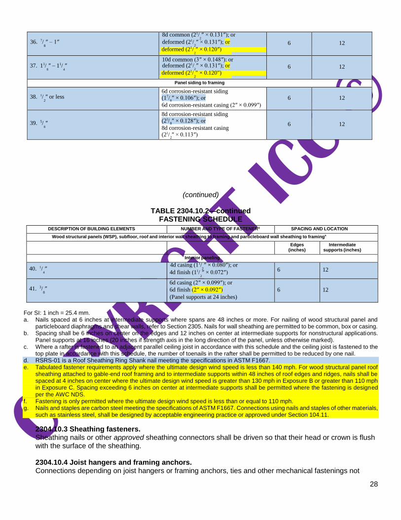
36. 7/ ″ – 1″
8
8d common (21/ ″ × 0.131″); or 2
deformed (21/ ″ × 0.131″); or 2
deformed (21/ ″ × 0.120″) 2
6
12
37. 11/ ″ – 11/ ″
8 4
10d common (3″ × 0.148″); or deformed (21/ ″ × 0.131″); or
2
deformed (21/ " × 0.120") 2
6
12
Panel siding to framing
38. 1/ ″ or less
2
6d corrosion-resistant siding (17/ ″ × 0.106″); or
8
6d corrosion-resistant casing (2″ × 0.099″)
6
12
39. 5/ ″ 8
8d corrosion-resistant siding (23/ ″ × 0.128″); or
8
8d corrosion-resistant casing (21/ ″ × 0.113″)
2
6
12
(continued)
TABLE 2304.10.2—continued FASTENING SCHEDULE
DESCRIPTION OF BUILDING ELEMENTS NUMBER AND TYPE OF FASTENERg SPACING AND LOCATION
Wood structural panels (WSP), subfloor, roof and interior wall sheathing to framing and particleboard wall sheathing to framinga
Edges (inches)
Intermediate supports (inches)
Interior paneling
40. 1/ ″ 4
4d casing (11/ ″ × 0.080″); or 2
4d finish (11/ ″ × 0.072″) 2
6 12
41. 3/ ″
8
6d casing (2″ × 0.099″); or
6d finish (2″ × 0.092″)
(Panel supports at 24 inches)
6
12
For SI: 1 inch = 25.4 mm. a. Nails spaced at 6 inches at intermediate supports where spans are 48 inches or more. For nailing of wood structural panel and
particleboard diaphragms and shear walls, refer to Section 2305. Nails for wall sheathing are permitted to be common, box or casing. b. Spacing shall be 6 inches on center on the edges and 12 inches on center at intermediate supports for nonstructural applications.
Panel supports at 16 inches (20 inches if strength axis in the long direction of the panel, unless otherwise marked). c. Where a rafter is fastened to an adjacent parallel ceiling joist in accordance with this schedule and the ceiling joist is fastened to the
top plate in accordance with this schedule, the number of toenails in the rafter shall be permitted to be reduced by one nail. d. RSRS-01 is a Roof Sheathing Ring Shank nail meeting the specifications in ASTM F1667. e. Tabulated fastener requirements apply where the ultimate design wind speed is less than 140 mph. For wood structural panel roof
sheathing attached to gable-end roof framing and to intermediate supports within 48 inches of roof edges and ridges, nails shall be spaced at 4 inches on center where the ultimate design wind speed is greater than 130 mph in Exposure B or greater than 110 mph in Exposure C. Spacing exceeding 6 inches on center at intermediate supports shall be permitted where the fastening is designed per the AWC NDS.
f. Fastening is only permitted where the ultimate design wind speed is less than or equal to 110 mph. g. Nails and staples are carbon steel meeting the specifications of ASTM F1667. Connections using nails and staples of other materials,
such as stainless steel, shall be designed by acceptable engineering practice or approved under Section 104.11.
2304.10.3 Sheathing fasteners. Sheathing nails or other approved sheathing connectors shall be driven so that their head or crown is flush with the surface of the sheathing.
2304.10.4 Joist hangers and framing anchors. Connections depending on joist hangers or framing anchors, ties and other mechanical fastenings not

29
otherwise covered are permitted where approved. The vertical load-bearing capacity, torsional moment capacity and deflection characteristics of joist hangers shall be determined in accordance with ASTM D7147.
2304.10.5 Other fasteners. Clips, staples, glues and other approved methods of fastening are permitted where approved.
2304.10.6 Fasteners and connectors in contact with preservative-treated and fire-retardant-treated wood. Fasteners, including nuts and washers, and connectors in contact with preservative-treated and fire-retardant-treated wood shall be in accordance with Sections 2304.10.6.1 through 2304.10.6.4. The coating weights for zinc-coated fasteners shall be in accordance with ASTM A153. Stainless steel driven fasteners shall be in accordance with the material requirements of ASTM F1667.
2304.10.6.1 Fasteners and connectors for preservative-treated wood. Fasteners, including nuts and washers, in contact with preservative-treated wood shall be of hot-dipped zinc-coated galvanized steel, stainless steel, silicon bronze or copper. Staples shall be of stainless steel. Fasteners other than nails, staples, timber rivets, wood screws and lag screws shall be permitted to be of mechanically deposited zinc-coated steel with coating weights in accordance with ASTM B695, Class 55 minimum. Connectors that are used in exterior applications and in contact with preservative-treated wood shall have coating types and weights in accordance with the treated wood or connector manufacturer’s recommendations. In the absence of manufacturer’s recommendations, not less than ASTM A653, Type G185 zinc-coated galvanized steel, or equivalent, shall be used.
Exception: Plain carbon steel fasteners, including nuts and washers, in SBX/DOT and zinc borate preservative-treated wood in an interior, dry environment shall be permitted.
2304.10.6.2 Fastenings for wood foundations. Fastenings, including nuts and washers, for wood foundations shall be as required in AWC PWF.
2304.10.6.3 Fasteners for fire-retardant-treated wood used in exterior applications or wet or damp locations. Fasteners, including nuts and washers, for fire-retardant-treated wood used in exterior applications or wet or damp locations shall be of hot-dipped zinc-coated galvanized steel, stainless steel, silicon bronze or copper. Staples shall be of stainless steel. Fasteners other than nails, staples, timber rivets, wood screws and lag screws shall be permitted to be of mechanically deposited zinc-coated steel with coating weights in accordance with ASTM B695, Class 55 minimum.
2304.10.6.4 Fasteners for fire-retardant-treated wood used in interior applications. Fasteners, including nuts and washers, for fire-retardant-treated wood used in interior locations shall be in accordance with the manufacturer’s recommendations. In the absence of manufacturer’s recommendations, Section 2304.10.6.3 shall apply.
2304.10.7 Load path. Where wall framing members are not continuous from the foundation sill to the roof, the members shall be secured to ensure a continuous load path. Where required, sheet metal clamps, ties or clips shall be formed of galvanized steel or other approved corrosion-resistant material not less than 0.0329-inch (0.836 mm) base metal thickness.
2304.10.8 Framing requirements. Wood columns and posts shall be framed to provide full end bearing. Alternatively, column-and-post end connections shall be designed to resist the full compressive loads, neglecting end-bearing capacity. Column-and-post end connections shall be fastened to resist lateral and net induced uplift forces.

30
2304.11 Heavy timber construction. Where a structure, portion thereof or individual structural elements are required by provisions of this code to be of heavy timber, the building elements therein shall comply with the applicable provisions of Sections 2304.11.1 through 2304.11.4. Minimum dimensions of heavy timber shall comply with the applicable requirements in Table 2304.11 based on roofs or floors supported and the configuration of each structural element, or in Sections 2304.11.2 through 2304.11.4. Lumber decking shall be in accordance with Section 2304.9.
TABLE 2304.11 MINIMUM DIMENSIONS OF HEAVY TIMBER STRUCTURAL MEMBERS
MINIMUM NOMINAL
SOLID SAWN SIZE
MINIMUM GLUED-LAMINATED NET SIZE
MINIMUM STRUCTURAL COMPOSITE LUMBER NET
SIZE
SUPPORTING HEAVY TIMBER STRUCTURAL
ELEMENTS
Width, inch
Depth, inch
Width, inch
Depth, inch Width, inch
Depth, inch
Floor loads only or combined floor and roof loads
Columns; Framed sawn or glued-laminated timber arches that spring from the floor line; Framed timber trusses
8 8 63/4 8
1/4 7 7
1/2
Wood beams and girders
6 10 5 101/2 5
1/4 9
1/2
Roof loads only
Columns (roof and ceiling loads); Lower half of: wood-frame or glued-laminated arches that spring from the floor line or from grade
6 8 5 81/4 5
1/4 7
1/2
Upper half of: wood-frame or glued-laminated arches that spring from the floor line or from grade
6 6 5 6 51/4 5
1/2
Framed timber trusses and other roof framing;a Framed or glued-laminated arches that spring from the top of walls or wall abutments
4b 6 3
b 6
7/8 3
1/2
b 5
1/2
For SI: 1 inch = 25.4 mm. a. Spaced members shall be permitted to be composed of two or more pieces not less than 3 inches nominal in thickness where blocked
solidly throughout their intervening spaces or where spaces are tightly closed by a continuous wood cover plate of not less than 2 inches nominal in thickness secured to the underside of the members. Splice plates shall be not less than 3 inches nominal in thickness.
b. Where protected by approved automatic sprinklers under the roof deck, framing members shall be not less than 3 inches nominal in width.

31
2304.11.1 Details of heavy timber structural members. Heavy timber structural members shall be detailed and constructed in accordance with Sections 2304.11.1 through 2304.11.1.3.
2304.11.1.1 Columns. Minimum dimensions of columns shall be in accordance with Table 2304.11. Columns shall be continuous or superimposed throughout all stories and connected in an approved manner. Girders and beams at column connections shall be closely fitted around columns and adjoining ends shall be cross tied to each other, or intertied by caps or ties, to transfer horizontal loads across joints. Wood bolsters shall not be placed on tops of columns unless the columns support roof loads only. Where traditional heavy timber detailing is used, connections shall be by means of reinforced concrete or metal caps with brackets, by properly designed steel or iron caps, with pintles and base plates, by timber splice plates affixed to the columns by metal connectors housed within the contact faces, or by other approved methods.
2304.11.1.2 Floor framing. Minimum dimensions of floor framing shall be in accordance with Table 2304.11. Approved wall plate boxes or hangers shall be provided where wood beams, girders or trusses rest on masonry or concrete walls. Where intermediate beams are used to support a floor, they shall rest on top of girders, or shall be supported by an approved metal hanger into which the ends of the beams shall be closely fitted. Where traditional heavy timber detailing is used, these connections shall be permitted to be supported by ledgers or blocks securely fastened to the sides of the girders.
2304.11.1.3 Roof framing. Minimum dimensions of roof framing shall be in accordance with Table 2304.11. Every roof girder and not less than every alternate roof beam shall be anchored to its supporting member to resist forces as required in Chapter 16.
2304.11.2 Partitions and walls. Partitions and walls shall comply with Section 2304.11.2.1 or 2304.11.2.2.
2304.11.2.1 Exterior walls. Exterior walls shall be permitted to be cross-laminated timber not less than 4 inches (102 mm) in thickness meeting the requirements of Section 2303.1.4. 2304.11.2.2 Interior walls and partitions. Interior walls and partitions shall be of solid wood construction formed by not less than two layers of 1-inch (25 mm) matched boards or laminated construction 4 inches (102 mm) thick, or of 1-hour fire-resistance-rated construction.
2304.11.3 Floors. Floors shall be without concealed spaces or with concealed spaces complying with Section 602.4.4.3. Wood floors shall be constructed in accordance with Section 2304.11.3.1 or 2304.11.3.2.
2304.11.3.1 Cross-laminated timber floors. Cross-laminated timber shall be not less than 4 inches (102 mm) in actual thickness. Cross-laminated timber shall be continuous from support to support and mechanically fastened to one another. Cross-laminated timber shall be permitted to be connected to walls without a shrinkage gap providing swelling or shrinking is considered in the design. Corbelling of masonry walls under the floor shall be permitted to be used.
2304.11.3.2 Sawn or glued-laminated plank floors. Sawn or glued-laminated plank floors shall be one of the following:

32
1. Sawn or glued-laminated planks, splined or tongue-and-groove, of not less than 3 inches (76 mm)
nominal in thickness covered with 1-inch (25 mm) nominal dimension tongue-and-groove flooring,
laid crosswise or diagonally, 15
/32
-inch (12 mm) wood structural panel or 1/2-inch (12.7 mm)
particleboard.
2. Planks not less than 4 inches (102 mm) nominal in width set on edge close together and well
spiked and covered with 1-inch (25 mm) nominal dimension flooring or 15
/32
-inch (12 mm) wood
structural panel or 1/2-inch (12.7 mm) particleboard.
The lumber shall be laid so that continuous lines of joints will occur only at points of support. Floors
shall not extend closer than 1/2 inch (12.7 mm) to walls. Such
1/2-inch (12.7 mm) space shall be covered
by a molding fastened to the wall and so arranged that it will not obstruct the swelling or shrinkage movements of the floor. Corbelling of masonry walls under the floor shall be permitted to be used in place of molding.
2304.11.4 Roof decks. Roofs shall be without concealed spaces or with concealed spaces complying with Section 602.4.4.3. Roof decks shall be constructed in accordance with Section 2304.11.4.1 or 2304.11.4.2. Other types of decking shall be an alternative that provides equivalent fire resistance and structural properties. Where supported by a wall, roof decks shall be anchored to walls to resist forces determined in accordance with Chapter 16. Such anchors shall consist of steel bolts, lags, screws or approved hardware of sufficient strength to resist prescribed forces.
2304.11.4.1 Cross-laminated timber roofs. Cross-laminated timber roofs shall be not less than 3 inches (76 mm) nominal in thickness and shall be continuous from support to support and mechanically fastened to one another.
2304.11.4.2 Sawn, wood structural panel, or glued-laminated plank roofs. Sawn, wood structural panel, or glued-laminated plank roofs shall be one of the following:
1. Sawn or glued laminated, splined or tongue-and-groove plank, not less than 2 inches (51 mm)
nominal in thickness.
2. 11/8-inch-thick (32 mm) wood structural panel (exterior glue).
3. Planks not less than 3 inches (76 mm) nominal in width, set on edge close together and laid as
required for floors. 2304.12 Protection against decay and termites. Wood shall be protected from decay and termites in accordance with the applicable provisions of Sections 2304.12.1 through 2304.12.4.
2304.12.1 Locations requiring waterborne preservatives or naturally durable wood. Wood used above ground in the locations specified in Sections 2304.12.1.1 through 2304.12.1.5 shall be naturally durable wood or preservative-treated wood using waterborne preservatives, in accordance with AWPA U1 for above-ground use.

33
2304.12.1.1 Joists, girders and subfloor. Wood joists or wood structural floors that are closer than 18 inches (457 mm) or wood girders that are closer than 12 inches (305 mm) to the exposed ground in crawl spaces or unexcavated areas located within the perimeter of the building foundation shall be of naturally durable or preservative-treated wood.
2304.12.1.2 Wood supported by exterior foundation walls. Wood framing members, including wood sheathing, that are in contact with exterior foundation walls and are less than 8 inches (203 mm) from exposed earth shall be of naturally durable or preservative-treated wood.
2304.12.1.3 Exterior walls below grade. Wood framing members and furring strips in direct contact with the interior of exterior masonry or concrete walls below grade shall be of naturally durable or preservative-treated wood.
2304.12.1.4 Sleepers and sills. Sleepers and sills on a concrete or masonry slab that is in direct contact with earth shall be of naturally durable or preservative-treated wood.
2304.12.1.5 Wood siding. Clearance between wood siding and earth on the exterior of a building shall be not less than 6 inches (152 mm) or less than 2 inches (51 mm) vertical from concrete steps, porch slabs, patio slabs and similar horizontal surfaces exposed to the weather except where siding, sheathing and wall framing are of naturally durable or preservative-treated wood.
2304.12.2 Other locations. Wood used in the locations specified in Sections 2304.12.2.1 through 2304.12.2.8 shall be naturally durable wood or preservative-treated wood in accordance with AWPA U1. Preservative-treated wood used in interior locations shall be protected with two coats of urethane, shellac, latex epoxy or varnish unless waterborne preservatives are used. Prior to application of the protective finish, the wood shall be dried in accordance with the manufacturer’s recommendations.
2304.12.2.1 Girder ends.
The ends of wood girders entering exterior masonry or concrete walls shall be provided with a 1/2-inch
(12.7 mm) airspace on top, sides and end, unless naturally durable or preservative-treated wood is used.
2304.12.2.2 Posts or columns. Posts or columns supporting permanent structures and supported by a concrete or masonry slab or footing that is in direct contact with the earth shall be of naturally durable or preservative-treated wood.
Exception: Posts or columns that meet all of the following:
1. Are not exposed to the weather, or are protected by a roof, eave, overhang, or other covering
if exposed to the weather.
2. Are supported by concrete piers or metal pedestals projected not less than 1 inch (25 mm)
above the slab or deck and are separated from the concrete pier by an impervious moisture barrier.
3. Are located not less than 8 inches (203 mm) above exposed earth.

34
2304.12.2.3 Supporting member for permanent appurtenances. Naturally durable or preservative-treated wood shall be utilized for those portions of wood members that form the structural supports of buildings, balconies, porches or similar permanent building appurtenances where such members are exposed to the weather without adequate protection from a roof, eave, overhang or other covering to prevent moisture or water accumulation on the surface or at joints between members.
Exception: Sawn lumber in buildings located in a geographical region where experience has demonstrated that climatic conditions preclude the need to use durable materials where the structure is exposed to the weather.
2304.12.2.4 Supporting members for permeable floors and roofs. Wood structural members that support moisture-permeable floors or roofs that are exposed to the weather, such as concrete or masonry slabs, shall be of naturally durable or preservative-treated wood unless separated from such floors or roofs by an impervious moisture barrier. The impervious moisture barrier system protecting the structure supporting floors shall provide positive drainage of water that infiltrates the moisture-permeable floor topping.
2304.12.2.5 Ventilation beneath balcony or elevated walking surfaces. Enclosed framing in exterior balconies and elevated walking surfaces that have weather-exposed surfaces shall be provided with openings that provide a net free cross-ventilation area not less than 1/150
of the area of each separate space.
2304.12.2.6 Wood in contact with the ground or fresh water. Wood used in contact with exposed earth shall be naturally durable for both decay and termite resistance or preservative treated in accordance with AWPA U1 for soil or fresh water use.
Exception: Untreated wood is permitted where such wood is continuously and entirely below the ground-water level or submerged in fresh water.
2304.12.2.6.1 Posts or columns. Posts and columns that are supporting permanent structures and embedded in concrete that is exposed to the weather or in direct contact with the earth shall be of preservative-treated wood.
2304.12.2.7 Termite protection. In geographical areas where hazard of termite damage is known to be very heavy, wood floor framing in the locations specified in Section 2304.12.1.1 and exposed framing of exterior decks or balconies shall be of naturally durable species (termite resistant) or preservative treated in accordance with AWPA U1 for the species, product preservative and end use or provided with approved methods of termite protection.
2304.12.2.8 Wood used in retaining walls and cribs. Wood installed in retaining or crib walls shall be preservative treated in accordance with AWPA U1 for soil and fresh water use.
2304.12.3 Attic ventilation. For attic ventilation, see Section 1202.2.2.
2304.12.4 Under-floor ventilation (crawl space). For under-floor ventilation (crawl space), see Section 1202.4.
2304.13 Long-term loading. Wood members supporting concrete, masonry or similar materials shall be checked for the effects of long-term

35
loading using the provisions of the ANSI/AWC NDS. The total deflection, including the effects of long-term loading, shall be limited in accordance with Section 1604.3.1 for these supported materials.
Exception: Horizontal wood members supporting masonry or concrete nonstructural floor or roof surfacing not more than 4 inches (102 mm) thick need not be checked for long-term loading.
SECTION 2305
GENERAL DESIGN REQUIREMENTS FOR LATERAL FORCE-RESISTING SYSTEMS
2305.1 General. Structures using wood-frame shear walls or wood-frame diaphragms to resist wind, seismic or other lateral loads shall be designed and constructed in accordance with AWC SDPWS and the applicable provisions of Sections 2305, 2306 and 2307.
2305.1.1 Openings in shear panels. Openings in shear panels that materially affect their strength shall be detailed on the plans and shall have their edges adequately reinforced to transfer all shearing stresses.
2305.2 Diaphragm deflection. The deflection of wood-frame diaphragms shall be determined in accordance with AWC SDPWS. The
deflection (dia
) of a blocked wood structural panel diaphragm uniformly fastened throughout with staples is
permitted to be calculated in accordance with Equation 23-1. If not uniformly fastened, the constant 0.188 (For SI: 1/1627) in the third term shall be modified by an approved method.
(Equation 23-1)
For SI:
where:
A = Area of chord cross section, in square inches
(mm2).
E = Modulus of elasticity of diaphragm chords, in
pounds per square inch (N/mm2).
en = Staple slip, in inches (mm) [see Table 2305.2(1)].
Gt = Panel rigidity through the thickness, in pounds per inch (N/mm) of panel width or depth [see Table 2305.2(2)].
L = Diaphragm length (dimension perpendicular to the direction of the applied load), in feet (mm).
v = Induced unit shear in pounds per linear foot (plf) (N/mm).
W = Diaphragm width [in the direction of applied force, in feet (mm)].
x = Distance from chord splice to nearest support, in feet (mm).
c =
Diaphragm chord splice slip at the induced unit shear, in inches (mm).
dia
= Maximum mid-span diaphragm deflection determined by elastic analysis, in inches (mm).
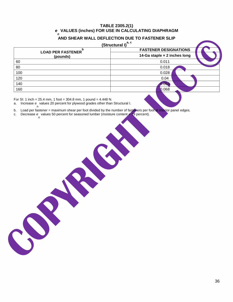
36
TABLE 2305.2(1)
en VALUES (inches) FOR USE IN CALCULATING DIAPHRAGM
AND SHEAR WALL DEFLECTION DUE TO FASTENER SLIP
(Structural I)a, c
LOAD PER FASTENERb
(pounds)
FASTENER DESIGNATIONS
14-Ga staple × 2 inches long
60 0.011
80 0.018
100 0.028
120 0.04
140 0.053
160 0.068
For SI: 1 inch = 25.4 mm, 1 foot = 304.8 mm, 1 pound = 4.448 N. a. Increase e
n values 20 percent for plywood grades other than Structural I.
b. Load per fastener = maximum shear per foot divided by the number of fasteners per foot at interior panel edges. c. Decrease e
n values 50 percent for seasoned lumber (moisture content < 19 percent).
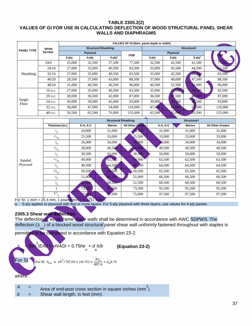
37
TABLE 2305.2(2) VALUES OF Gt FOR USE IN CALCULATING DEFLECTION OF WOOD STRUCTURAL PANEL SHEAR
WALLS AND DIAPHRAGMS
PANEL TYPE
SPAN RATING
VALUES OF Gt (lb/in. panel depth or width)
Structural Sheathing Structural I
Plywood
OSB Plywood
OSB 3-ply 4-ply 5-plya
3-ply 4-ply 5-plya
Sheathing
24/0 25,000 32,500 37,500 77,500 32,500 42,500 41,500 77,500
24/16 27,000 35,000 40,500 83,500 35,000 45,500 44,500 83,500
32/16 27,000 35,000 40,500 83,500 35,000 45,500 44,500 83,500
40/20 28,500 37,000 43,000 88,500 37,000 48,000 47,500 88,500
48/24 31,000 40,500 46,500 96,000 40,500 52,500 51,000 96,000
Single Floor
16 o.c. 27,000 35,000 40,500 83,500 35,000 45,500 44,500 83,500
20 o.c. 28,000 36,500 42,000 87,000 36,500 47,500 46,000 87,000
24 o.c. 30,000 39,000 45,000 93,000 39,000 50,500 49,500 93,000
32 o.c. 36,000 47,000 54,000 110,000 47,000 61,000 59,500 110,000
48 o.c. 50,500 65,500 76,000 155,000 65,500 85,000 83,500 155,000
Structural Sheathing Structural I
Thickness (in.) A-A, A-C Marine All Other Grades A-A, A-C Marine All Other Grades
Sanded
Plywood
1/ 4 24,000 31,000 24,000 31,000 31,000 31,000
11/ 32 25,500 33,000 25,500 33,000 33,000 33,000
3/ 8 26,000 34,000 26,000 34,000 34,000 34,000
15/ 32 38,000 49,500 38,000 49,500 49,500 49,500
1/ 2 38,500 50,000 38,500 50,000 50,000 50,000
19/ 32 49,000 63,500 49,000 63,500 63,500 63,500
5/ 8 49,500 64,500 49,500 64,500 64,500 64,500
23/ 32 50,500 65,500 50,500 65,500 65,500 65,500
3/ 4 51,000 66,500 51,000 66,500 66,500 66,500
7/ 8 52,500 68,500 52,500 68,500 68,500 68,500
1 73,500 95,500 73,500 95,500 95,500 95,500
11/ 8
75,000 97,500 75,000 97,500 97,500 97,500
For SI: 1 inch = 25.4 mm, 1 pound/inch = 0.1751 N/mm. a. 5-ply applies to plywood with five or more layers. For 5-ply plywood with three layers, use values for 4-ply panels.
2305.3 Shear wall deflection. The deflection of wood-frame shear walls shall be determined in accordance with AWC SDPWS. The
deflection (sw
) of a blocked wood structural panel shear wall uniformly fastened throughout with staples is
permitted to be calculated in accordance with Equation 23-2.
sw
= 8vh3/EAb + vh/4Gt + 0.75he
n + d
ah/b (Equation 23-2)
For SI where:
A =
Area of end-post cross section in square inches (mm2).
b = Shear wall length, in feet (mm).
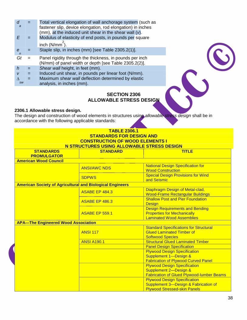
38
da = Total vertical elongation of wall anchorage system (such as
fastener slip, device elongation, rod elongation) in inches (mm), at the induced unit shear in the shear wall (v).
E = Modulus of elasticity of end posts, in pounds per square
inch (N/mm2).
en = Staple slip, in inches (mm) [see Table 2305.2(1)].
Gt = Panel rigidity through the thickness, in pounds per inch (N/mm) of panel width or depth [see Table 2305.2(2)].
h = Shear wall height, in feet (mm). v = Induced unit shear, in pounds per linear foot (N/mm).
sw
= Maximum shear wall deflection determined by elastic analysis, in inches (mm).
SECTION 2306
ALLOWABLE STRESS DESIGN 2306.1 Allowable stress design. The design and construction of wood elements in structures using allowable stress design shall be in accordance with the following applicable standards:
TABLE 2306.1 STANDARDS FOR DESIGN AND
CONSTRUCTION OF WOOD ELEMENTS I N STRUCTURES USING ALLOWABLE STRESS DESIGN
STANDARDS PROMULGATOR
STANDARD TITLE
American Wood Council
ANSI/AWC NDS
National Design Specification for Wood Construction
SDPWS Special Design Provisions for Wind and Seismic
American Society of Agricultural and Biological Engineers
ASABE EP 484.3
Diaphragm Design of Metal-clad, Wood-Frame Rectangular Buildings
ASABE EP 486.3 Shallow Post and Pier Foundation Design
ASABE EP 559.1 Design Requirements and Bending Properties for Mechanically Laminated Wood Assemblies
APA—The Engineered Wood Association
ANSI 117
Standard Specifications for Structural Glued Laminated Timber of Softwood Species
ANSI A190.1 Structural Glued Laminated Timber
Panel Design Specification
Plywood Design Specification Supplement 1—Design & Fabrication of Plywood Curved Panel
Plywood Design Specification Supplement 2—Design & Fabrication of Glued Plywood-lumber Beams
Plywood Design Specification Supplement 3—Design & Fabrication of Plywood Stressed-skin Panels
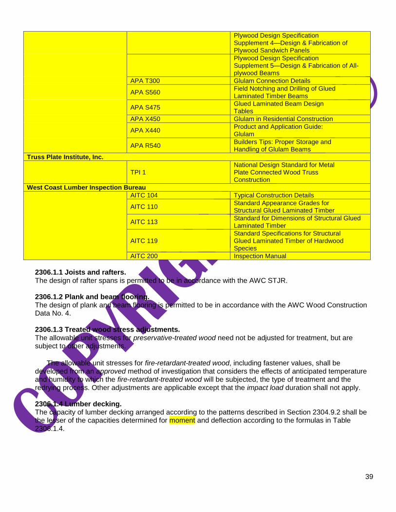
39
Plywood Design Specification Supplement 4—Design & Fabrication of Plywood Sandwich Panels
Plywood Design Specification Supplement 5—Design & Fabrication of All-plywood Beams
APA T300 Glulam Connection Details
APA S560 Field Notching and Drilling of Glued Laminated Timber Beams
APA S475 Glued Laminated Beam Design Tables
APA X450 Glulam in Residential Construction
APA X440 Product and Application Guide: Glulam
APA R540 Builders Tips: Proper Storage and Handling of Glulam Beams
Truss Plate Institute, Inc.
TPI 1
National Design Standard for Metal Plate Connected Wood Truss Construction
West Coast Lumber Inspection Bureau
AITC 104 Typical Construction Details
AITC 110 Standard Appearance Grades for Structural Glued Laminated Timber
AITC 113 Standard for Dimensions of Structural Glued Laminated Timber
AITC 119 Standard Specifications for Structural Glued Laminated Timber of Hardwood Species
AITC 200 Inspection Manual
2306.1.1 Joists and rafters. The design of rafter spans is permitted to be in accordance with the AWC STJR.
2306.1.2 Plank and beam flooring. The design of plank and beam flooring is permitted to be in accordance with the AWC Wood Construction Data No. 4.
2306.1.3 Treated wood stress adjustments. The allowable unit stresses for preservative-treated wood need not be adjusted for treatment, but are subject to other adjustments.
The allowable unit stresses for fire-retardant-treated wood, including fastener values, shall be
developed from an approved method of investigation that considers the effects of anticipated temperature and humidity to which the fire-retardant-treated wood will be subjected, the type of treatment and the redrying process. Other adjustments are applicable except that the impact load duration shall not apply.
2306.1.4 Lumber decking. The capacity of lumber decking arranged according to the patterns described in Section 2304.9.2 shall be the lesser of the capacities determined for moment and deflection according to the formulas in Table 2306.1.4.

40
TABLE 2306.1.4 ALLOWABLE LOADS FOR LUMBER DECKING
PATTERN ALLOWABLE AREA LOAD
a
Moment Deflection
Simple span
Two-span continuous
Combination simple- and two-span continuous
Cantilevered pieces intermixed
Controlled random layup
Mechanically laminated decking
2-inch decking
3-inch and 4-inch decking
For SI: 1 inch = 25.4 mm.
a. wb= Allowable total uniform load limited by moment.
w = Allowable total uniform load limited by deflection.
d = Actual decking thickness. l = Span of decking.
Fb = Allowable bending stress adjusted by applicable factors.
E = Modulus of elasticity adjusted by applicable factors.
2306.2 Wood-frame diaphragms. Wood-frame diaphragms shall be designed and constructed in accordance with AWC SDPWS. Where panels are fastened to framing members with staples, requirements and limitations of AWC SDPWS shall be met and the allowable shear values set forth in Table 2306.2(1) or 2306.2(2) shall be permitted. The allowable shear values in Tables 2306.2(1) and 2306.2(2) are permitted to be increased 40 percent for wind design.

41
TABLE 2306.2(1)
ALLOWABLE SHEAR VALUES (POUNDS PER FOOT) FOR WOOD STRUCTURAL PANEL DIAPHRAGMS
UTILIZING STAPLES WITH FRAMING OF DOUGLAS FIR-LARCH, OR SOUTHERN PINEa FOR WIND OR
SEISMIC LOADINGf
For SI: 1 inch = 25.4 mm, 1 pound per foot = 14.5939 N/m. a. For framing of other species: (1) Find specific gravity for species of lumber in ANSI/AWC NDS. (2) For staples find shear value from
table for Structural I panels (regardless of actual grade) and multiply value by 0.82 for species with specific gravity of 0.42 or greater, or 0.65 for all other species.
b. Space fasteners maximum 12 inches on center along intermediate framing members (6 inches on center where supports are spaced 48 inches on center).
c. Framing at adjoining panel edges shall be 3 inches nominal or wider.
d. Staples shall have a minimum crown width of 7/16
inch and shall be installed with their crowns parallel to the long dimension of the
framing members. e. The minimum nominal width of framing members not located at boundaries or adjoining panel edges shall be 2 inches. f. For shear loads of normal or permanent load duration as defined by the ANSI/AWC NDS, the values in the table shall be multiplied
by 0.63 or 0.56, respectively. g. For Case 1 through 6 descriptions see Figure 2306.2(1).

42
FIGURE 2306.2(1) CASES 1 THROUGH 6 FOR USE WITH TABLE 2306.2(1)
TABLE 2306.2(2)
ALLOWABLE SHEAR VALUES (POUNDS PER FOOT) FOR WOOD STRUCTURAL PANEL BLOCKED DIAPHRAGMS UTILIZING MULTIPLE ROWS OF STAPLES (HIGH-LOAD DIAPHRAGMS) WITH FRAMING
OF DOUGLAS FIR-LARCH OR SOUTHERN PINEa FOR WIND OR SEISMIC LOADING
b, g, h
PANEL GRADE
c
STAPLE
GAGEf
MINIMUM FASTENER
PENETRATION
IN FRAMING (inches)
MINIMUM NOMINAL
PANEL THICKNES
S (inch)
MINIMUM NOMINAL WIDTH OF FRAMING
MEMBER AT ADJOINING
PANEL EDGES AND
BOUNDARIES
e
LINES OF FASTENER
S
BLOCKED DIAPHRAGMS
Cases 1 and 2d
Fastener Spacing Per Line at Boundaries
(inches)i
4 21/2 2
Fastener Spacing Per Line at
Other Panel Edges (inches)i
6 4 4 3 3 2
Structural I grades
14 gage staples
2
15/32
3 2
600
600
860 960 1,06
0 1,20
0
4 3 860
900
1,160
1,295
1,295
1,400
19/32
3 2
600
600
875 960 1,07
5 1,20
0
4 3 875
900
1,175
1,440
1,475
1,795
Sheathing single floor and other grades covered in DOC PS 1 and PS 2
14 gage staples
2
15/32
3 2
540
540
735 865 915 1,08
0
4 3 735
810
1,005
1,105
1,105
1,195
19/32
3 2
600
600
865 960 1,06
5 1,20
0
4 3 865
900
1,130
1,430
1,370
1,485
23/32
4 3 865
900
1,130
1,490
1,430
1,545
For SI: 1 inch = 25.4 mm, 1 pound per foot = 14.5939 N/m. a. For framing of other species: (1) Find specific gravity for species of framing lumber in ANSI/AWC NDS. (2) For staples, find shear
value from table for Structural I panels (regardless of actual grade) and multiply value by 0.82 for species with specific gravity of 0.42 or greater, or 0.65 for all other species.
b. Fastening along intermediate framing members: Space fasteners not greater than 12 inches on center, except 6 inches on center for spans greater than 32 inches.
c. Panels conforming to DOC PS 1 or PS 2.

43
d. This table gives shear values for Cases 1 and 2 as shown in Table 2306.2(1). The values shown are applicable to Cases 3, 4, 5 and 6 as shown in Table 2306.2(1), providing fasteners at all continuous panel edges are spaced in accordance with the boundary fastener spacing.
e. The minimum nominal depth of framing members shall be 3 inches nominal. The minimum nominal width of framing members not located at boundaries or adjoining panel edges shall be 2 inches.
f. Staples shall have a minimum crown width of 7/16
inch, and shall be installed with their crowns parallel to the long dimension of the
framing members. g. High-load diaphragms shall be subject to special inspection in accordance with Section 1705.5.1. h. For shear loads of normal or permanent load duration as defined by the ANSI/AWC NDS, the values in the table shall be multiplied
by 0.63 or 0.56, respectively. i. For fastener spacing diagrams see Figure 2306.2(2).
For SI: 1 inch = 25.4 mm.
FIGURE 2306.2(2)
FASTENER SPACING DIAGRAMS FOR USE WITH TABLE 2306.2(2)
2306.2.1 Gypsum board diaphragm ceilings. Gypsum board diaphragm ceilings shall be in accordance with Section 2508.6.
2306.3 Wood-frame shear walls. Wood-frame shear walls shall be designed and constructed in accordance with AWC SDPWS. Where panels are fastened to framing members with staples, requirements and limitations of AWC SDPWS shall be met and the allowable shear values set forth in Table 2306.3(1), 2306.3(2) or 2306.3(3) shall be permitted. The allowable shear values in Tables 2306.3(1) and 2306.3(2) are permitted to be increased 40 percent for wind design. Panels complying with ANSI/APA PRP-210 shall be permitted to use design values for Plywood Siding in the AWC SDPWS.

44
TABLE 2306.3(1) ALLOWABLE SHEAR VALUES (POUNDS PER FOOT) FOR WOOD STRUCTURAL PANEL SHEAR
WALLS UTILIZING STAPLES WITH FRAMING OF DOUGLAS FIR-LARCH OR SOUTHERN PINEa FOR
WIND OR SEISMIC LOADINGb, f, g, i
PANEL GRADE
MINIMUM NOMINAL
PANEL THICKNESS
(inch)
MINIMUM FASTENER
PENETRATION IN
FRAMING (inches)
PANELS APPLIED
DIRECT TO FRAMING
PANELS APPLIED OVER 1/2" OR
5/8" GYPSUM SHEATHING
Staple length
and
gageh
(inches)
Fastener spacing at panel edges
(inches)
Staple length
and
gageh
(inches)
Fastener spacing at panel edges
(inches)
6 4 3 2d 6 4 3 2
d
Structural I sheathing
3/8
1 1
1/2
16
Gage
155 235 315 400
2 16 Gage
155 235 310 400
7/16
170 260 345 440 155 235 310 400
15/32
185 280 375 475 155 235 300 400
Sheathing, plywood
sidinge
except Group 5 Species, ANSI/APA PRP
210 sidinge
5/16
c or
1/4c
1
11/2
16
Gage
145 220 295 375
2 16 Gage
110 165 220 285
3/8
140 210 280 360 140 210 280 360
7/16
155 230 310 395 140 210 280 360
15/32
170 255 335 430 140 210 280 360
19/32
13/4
16
Gage 185 280 375 475 — — — — —
For SI: 1 inch = 25.4 mm, 1 pound per foot = 14.5939 N/m. a. For framing of other species: (1) Find specific gravity for species of lumber in ANSI/AWC NDS. (2) For staples find shear value from
table for Structural I panels (regardless of actual grade) and multiply value by 0.82 for species with specific gravity of 0.42 or greater, or 0.65 for all other species.
b. Panel edges backed with 2-inch nominal or wider framing. Install panels either horizontally or vertically. Space fasteners maximum
6 inches on center along intermediate framing members for 3/8-inch and
7/16
-inch panels installed on studs spaced 24 inches on
center. For other conditions and panel thickness, space fasteners maximum 12 inches on center on intermediate supports.
c. 3/8-inch panel thickness or siding with a span rating of 16 inches on center is the minimum recommended where applied directly to
framing as exterior siding. For grooved panel siding, the nominal panel thickness is the thickness of the panel measured at the point of fastening.
d. Framing at adjoining panel edges shall be 3 inches nominal or wider. e. Values apply to all-veneer plywood. Thickness at point of fastening on panel edges governs shear values. f. Where panels are applied on both faces of a wall and fastener spacing is less than 6 inches on center on either side, panel joints
shall be offset to fall on different framing members, or framing shall be 3 inches nominal or thicker at adjoining panel edges. g. In Seismic Design Category D, E or F, where shear design values exceed 350 pounds per linear foot, all framing members receiving
edge fastening from abutting panels shall be not less than a single 3-inch nominal member, or two 2-inch nominal members fastened together in accordance with Section 2306.1 to transfer the design shear value between framing members. Wood structural panel joint and sill plate nailing shall be staggered at all panel edges. See AWC SDPWS for sill plate size and anchorage requirements.
h. Staples shall have a minimum crown width of 7/16
inch and shall be installed with their crowns parallel to the long dimension of the
framing members.
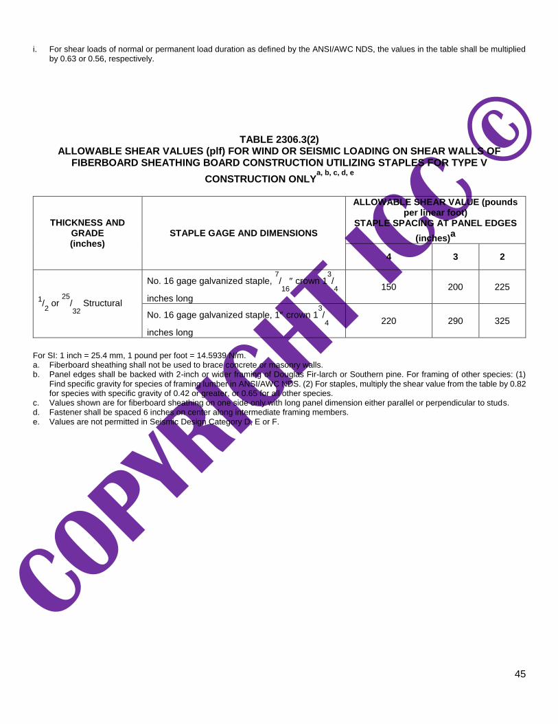
45
i. For shear loads of normal or permanent load duration as defined by the ANSI/AWC NDS, the values in the table shall be multiplied by 0.63 or 0.56, respectively.
TABLE 2306.3(2) ALLOWABLE SHEAR VALUES (plf) FOR WIND OR SEISMIC LOADING ON SHEAR WALLS OF
FIBERBOARD SHEATHING BOARD CONSTRUCTION UTILIZING STAPLES FOR TYPE V
CONSTRUCTION ONLYa, b, c, d, e
THICKNESS AND GRADE (inches)
STAPLE GAGE AND DIMENSIONS
ALLOWABLE SHEAR VALUE (pounds per linear foot)
STAPLE SPACING AT PANEL EDGES
(inches)a
4 3 2
1/2 or
25/32
Structural
No. 16 gage galvanized staple, 7/16
crown 1
3/4
inches long
150 200 225
No. 16 gage galvanized staple, 1 crown 13/4
inches long
220 290 325
For SI: 1 inch = 25.4 mm, 1 pound per foot = 14.5939 N/m. a. Fiberboard sheathing shall not be used to brace concrete or masonry walls. b. Panel edges shall be backed with 2-inch or wider framing of Douglas Fir-larch or Southern pine. For framing of other species: (1)
Find specific gravity for species of framing lumber in ANSI/AWC NDS. (2) For staples, multiply the shear value from the table by 0.82 for species with specific gravity of 0.42 or greater, or 0.65 for all other species.
c. Values shown are for fiberboard sheathing on one side only with long panel dimension either parallel or perpendicular to studs. d. Fastener shall be spaced 6 inches on center along intermediate framing members. e. Values are not permitted in Seismic Design Category D, E or F.

46
TABLE 2306.3(3) ALLOWABLE SHEAR VALUES FOR WIND OR SEISMIC FORCES FOR SHEAR WALLS OF LATH AND
PLASTER OR GYPSUM BOARD WOOD FRAMED WALL ASSEMBLIES UTILIZING STAPLES
TYPE OF MATERIAL
THICKNESS OF MATERIAL
WALL CONSTRUCTION
STAPLE SPACINGb
MAXIMUM (inches)
SHEAR VALUEa, c
(plf)
MINIMUM STAPLE SIZE f, g
1. Expanded metal or woven wire lath and Portland cement plaster
7/ ″
8
Unblocked
6
180
No. 16 gage galv. staple, 7/ ″ legs
8
2. Gypsum lath, plain or perforated
3/ ″ lath and 1/ ″ 8 2
plaster Unblocked 5 100 No. 16 gage galv. staple, 11/ ″ long
8
3. Gypsum sheathing
1/ ″ × 2′ × 8′ 2
Unblocked 4 75 No. 16 gage galv. staple, 13/ ″ long
4 1/ ″ ×4′ 2
Blockedd
Unblocked
4
7
175 100
4. Gypsum board, gypsum veneer base or water- resistant gypsum backing board
1/ ″
2
Unblockedd 7 75
No. 16 gage galv. staple, 11/ ″ long
2
Unblockedd 4 110
Unblocked 7 100
Unblocked 4 125
Blockede 7 125
Blockede 4 150
5/ ″
8
Unblockedd
7 115
No. 16 gage galv. staple, 15/ ″ long
8
4 145
Blockede
7 145
4 175
Blockede
Two-ply
Base ply: 9
Face ply: 7 250
No. 16 gage galv. staple 15/ ″ long 8
No. 15 gage galv. staple, 21/ ″ long 4
For SI: 1 inch = 25.4 mm, 1 foot = 304.8 mm, 1 pound per foot = 14.5939 N/m. a. These shear walls shall not be used to resist loads imposed by masonry or concrete walls (see AWC SDPWS). Values shown are
for short-term loading due to wind or seismic loading. Walls resisting seismic loads shall be subject to the limitations in Section 12.2.1 of ASCE 7. Values shown shall be reduced 25 percent for normal loading.
b. Applies to fastening at studs, top and bottom plates and blocking. c. Except as noted, shear values are based on a maximum framing spacing of 16 inches on center. d. Maximum framing spacing of 24 inches on center. e. All edges are blocked, and edge fastening is provided at all supports and all panel edges.
f. Staples shall have a minimum crown width of 7/16
inch, measured outside the legs, and shall be installed with their crowns parallel
to the long dimension of the framing members.
g. Staples for the attachment of gypsum lath and woven-wire lath shall have a minimum crown width of 3/4 inch, measured outside the
legs.
SECTION 2307
LOAD AND RESISTANCE FACTOR DESIGN 2307.1 Load and resistance factor design. The design and construction of wood elements and structures using load and resistance factor design shall be in accordance with ANSI/AWC NDS and AWC SDPWS.
SECTION 2308
CONVENTIONAL LIGHT-FRAME CONSTRUCTION 2308.1 General. The requirements of this section are intended for conventional light-frame construction. Other construction

47
methods are permitted to be used, provided that a satisfactory design is submitted showing compliance with other provisions of this code. Interior nonload-bearing partitions, ceilings and curtain walls of conventional light-frame construction are not subject to the limitations of Section 2308.2. Detached one- and two-family dwellings and townhouses not more than three stories above grade plane in height with a separate means of egress and their accessory structures shall comply with the International Residential Code.
2308.1.1 Portions exceeding limitations of conventional light-frame construction. Where portions of a building of otherwise conventional light-frame construction exceed the limits of Section 2308.2, those portions and the supporting load path shall be designed in accordance with accepted engineering practice and the provisions of this code. For the purposes of this section, the term “portions” shall mean parts of buildings containing volume and area such as a room or a series of rooms. The extent of such design need only demonstrate compliance of the nonconventional light-framed elements with other applicable provisions of this code and shall be compatible with the performance of the conventional light-framed system.
2308.1.2 Connections and fasteners. Connectors and fasteners used in conventional construction shall comply with the requirements of Section 2304.10.
2308.2 Limitations. Buildings are permitted to be constructed in accordance with the provisions of conventional light-frame construction, subject to the limitations in Sections 2308.2.1 through 2308.2.6.
2308.2.1 Stories. Structures of conventional light-frame construction shall be limited in story height in accordance with Table 2308.2.1.
TABLE 2308.2.1 ALLOWABLE STORY HEIGHT
SEISMIC DESIGN CATEGORY ALLOWABLE STORY
ABOVE GRADE PLANE
A and B Three stories
C Two stories
D and Ea One story
For SI:1 inch = 25.4 mm. a. For the purposes of this section, for buildings assigned to Seismic Design Category D or E, cripple walls shall be considered to be
a story unless cripple walls are solid blocked and do not exceed 14 inches in height.
2308.2.2 Allowable floor-to-floor height. Maximum floor-to-floor height shall not exceed 11 feet, 7 inches (3531 mm). Exterior bearing wall and interior braced wall heights shall not exceed a stud height of 10 feet (3048 mm).
2308.2.3 Allowable loads. Loads shall be in accordance with Chapter 16 and shall not exceed the following:
1. Average dead loads shall not exceed 15 psf (718 N/m2) for combined roof and ceiling, exterior walls,
floors and partitions.
Exceptions:
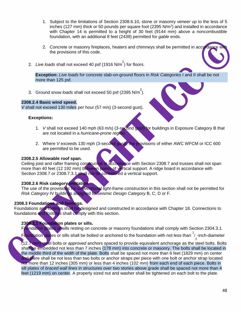
48
1. Subject to the limitations of Section 2308.6.10, stone or masonry veneer up to the less of 5 inches (127 mm) thick or 50 pounds per square foot (2395 N/m2) and installed in accordance with Chapter 14 is permitted to a height of 30 feet (9144 mm) above a noncombustible foundation, with an additional 8 feet (2439) permitted for gable ends.
2. Concrete or masonry fireplaces, heaters and chimneys shall be permitted in accordance with
the provisions of this code.
2. Live loads shall not exceed 40 psf (1916 N/m2) for floors.
Exception: Live loads for concrete slab-on-ground floors in Risk Categories I and II shall be not more than 125 psf.
3. Ground snow loads shall not exceed 50 psf (2395 N/m2).
2308.2.4 Basic wind speed. V shall not exceed 130 miles per hour (57 m/s) (3-second gust).
Exceptions:
1. V shall not exceed 140 mph (63 m/s) (3-second gust) for buildings in Exposure Category B that
are not located in a hurricane-prone region.
2. Where V exceeds 130 mph (3-second gust), the provisions of either AWC WFCM or ICC 600
are permitted to be used.
2308.2.5 Allowable roof span. Ceiling joist and rafter framing constructed in accordance with Section 2308.7 and trusses shall not span more than 40 feet (12 192 mm) between points of vertical support. A ridge board in accordance with Section 2308.7 or 2308.7.3.1 shall not be considered a vertical support.
2308.2.6 Risk category limitation. The use of the provisions for conventional light-frame construction in this section shall not be permitted for Risk Category IV buildings assigned to Seismic Design Category B, C, D or F.
2308.3 Foundations and footings. Foundations and footings shall be designed and constructed in accordance with Chapter 18. Connections to foundations and footings shall comply with this section.
2308.3.1 Foundation plates or sills. Foundation plates or sills resting on concrete or masonry foundations shall comply with Section 2304.3.1.
Foundation plates or sills shall be bolted or anchored to the foundation with not less than 1/2-inch-diameter
(12.7 mm) steel bolts or approved anchors spaced to provide equivalent anchorage as the steel bolts. Bolts shall be embedded not less than 7 inches (178 mm) into concrete or masonry. The bolts shall be located in the middle third of the width of the plate. Bolts shall be spaced not more than 6 feet (1829 mm) on center and there shall be not less than two bolts or anchor straps per piece with one bolt or anchor strap located not more than 12 inches (305 mm) or less than 4 inches (102 mm) from each end of each piece. Bolts in sill plates of braced wall lines in structures over two stories above grade shall be spaced not more than 4 feet (1219 mm) on center. A properly sized nut and washer shall be tightened on each bolt to the plate.

49
2308.3.1.1 Braced wall line sill plate anchorage in Seismic Design Category D. Sill plates along braced wall lines in buildings assigned to Seismic Design Category D shall be
anchored with not less than 1/2-inch (12.7 mm) diameter anchor bolts with steel plate washers between
the foundation sill plate and the nut, or approved anchor straps load-rated in accordance with Section 2304.10.4 and spaced to provide equivalent anchorage. Plate washers shall be not less than 0.229 inch by 3 inches by 3 inches (5.82 mm by 76 mm by 76 mm) in size. The hole in the plate washer is
permitted to be diagonally slotted with a width of up to 3/16
inch (4.76 mm) larger than the bolt diameter
and a slot length not to exceed 13/4 inches (44 mm), provided that a standard cut washer is placed
between the plate washer and the nut.
2308.3.1.2 Braced wall line sill plate anchorage in Seismic Design Category E. Sill plates along braced wall lines in buildings assigned to Seismic Design Category E shall be
anchored with not less than 5/8-inch diameter (15.9 mm) anchor bolts with steel plate washers between
the foundation sill plate and the nut, or approved anchor straps load-rated in accordance with Section 2304.10.4 and spaced to provide equivalent anchorage. Plate washers shall be not less than 0.229 inch by 3 inches by 3 inches (5.82 mm by 76 mm by 76 mm) in size. The hole in the plate washer is
permitted to be diagonally slotted with a width of up to 3/16
inch (4.76 mm) larger than the bolt diameter
and a slot length not to exceed 13/4 inches (44 mm), provided that a standard cut washer is placed
between the plate washer and the nut. 2308.4 Floor framing. Floor framing shall comply with this section.
2308.4.1 Girders. Girders for single-story construction or girders supporting loads from a single floor shall be not less than 4 inches by 6 inches (102 mm by 152 mm) for spans 6 feet (1829 mm) or less, provided that girders are spaced not more than 8 feet (2438 mm) on center. Other girders shall be designed to support the loads specified in this code. Girder end joints shall occur over supports.
Where a girder is spliced over a support, an adequate tie shall be provided. The ends of beams or
girders supported on masonry or concrete shall not have less than 3 inches (76 mm) of bearing.
2308.4.1.1 Allowable girder spans. The allowable spans of girders that are fabricated of dimension lumber shall not exceed the values set forth in Table 2308.4.1.1(1) or 2308.4.1.1(2).

50
TABLE 2308.4.1.1(1)
HEADER AND GIRDER SPANSa, b
FOR EXTERIOR BEARING WALLS (Maximum spans for Douglas fir-larch, hem-fir, Southern pine and spruce-pine-fir and required number
of jack studs)
GIRDERS AND
HEADERS SUPPORTING
SIZE
GROUND SNOW LOAD (psf)e
30 50 70
Building widthc (feet)
12 24 36 12 24 36 12 24 36
Spanf NJd
Spanf NJd
Spanf NJd
Spanf NJd
Spanf NJd
Spanf NJd
Spanf NJd
Spanf NJd
Spanf NJd
Roof and ceiling
1-2 × 6 4-0 1 3-1 2 2-7 2 3-5 1 2-8 2 2-3 2 3-0 2 2-4 2 2-0 2
1-2 × 8 5-1 2 3-11 2 3-3 2 4-4 2 3-4 2 2-10 2 3-10 2 3-0 2 2-6 3
1-2 × 10 6-0 2 4-8 2 3-11 2 5-2 2 4-0 2 3-4 3 4-7 2 3-6 3 3-0 3
1-2 × 12 7-1 2 5-5 2 4-7 3 6-1 2 4-8 3 3-11 3 5-5 2 4-2 3 3-6 3
2-2 × 4 4-0 1 3-1 1 2-7 1 3-5 1 2-7 1 2-2 1 3-0 1 2-4 1 2-0 1
2-2 × 6 6-0 1 4-7 1 3-10 1 5-1 1 3-11 1 3-3 2 4-6 1 3-6 2 2-11 2
2-2 × 8 7-7 1 5-9 1 4-10 2 6-5 1 5-0 2 4-2 2 5-9 1 4-5 2 3-9 2
2-2 × 10 9-0 1 6-10 2 5-9 2 7-8 2 5-11 2 4-11 2 6-9 2 5-3 2 4-5 2
2-2 × 12 10-7 2 8-1 2 6-10 2 9-0 2 6-11 2 5-10 2 8-0 2 6-2 2 5-2 3
3-2 × 8 9-5 1 7-3 1 6-1 1 8-1 1 6-3 1 5-3 2 7-2 1 5-6 2 4-8 2
3-2 × 10 11-3 1 8-7 1 7-3 2 9-7 1 7-4 2 6-2 2 8-6 1 6-7 2 5-6 2
3-2 × 12 13-2 1 10-1 2 8-6 2 11-3 2 8-8 2 7-4 2 10-0 2 7-9 2 6-6 2
4-2 × 8 10-11 1 8-4 1 7-0 1 9-4 1 7-2 1 6-0 1 8-3 1 6-4 1 5-4 2
4-2 × 10 12-11 1 9-11 1 8-4 1 11-1 1 8-6 1 7-2 2 9-10 1 7-7 2 6-4 2
4-2 × 12 15-3 1 11-8 1 9-10 2 13-0 1 10-0 2 8-5 2 11-7 1 8-11 2 7-6 2
Roof, ceiling and one center- bearing floor
1-2 × 6 3-3 1 2-7 2 2-2 2 3-0 2 2-4 2 2-0 2 2-9 2 2-2 2 1-10 2
1-2 × 8 4-1 2 3-3 2 2-9 2 3-9 2 3-0 2 2-6 3 3-6 2 2-9 2 2-4 3
1-2 × 10 4-11 2 3-10 2 3-3 3 4-6 2 3-6 3 3-0 3 4-1 2 3-3 3 2-9 3
1-2 × 12 5-9 2 4-6 3 3-10 3 5-3 2 4-2 3 3-6 3 4-10 3 3-10 3 3-3 4
2-2 × 4 3-3 1 2-6 1 2-2 1 3-0 1 2-4 1 2-0 1 2-8 1 2-2 1 1-10 1
2-2 × 6 4-10 1 3-9 1 3-3 2 4-5 1 3-6 2 3-0 2 4-1 1 3-3 2 2-9 2
2-2 × 8 6-1 1 4-10 2 4-1 2 5-7 2 4-5 2 3-9 2 5-2 2 4-1 2 3-6 2
2-2 × 10 7-3 2 5-8 2 4-10 2 6-8 2 5-3 2 4-5 2 6-1 2 4-10 2 4-1 2
2-2 × 12 8-6 2 6-8 2 5-8 2 7-10 2 6-2 2 5-3 3 7-2 2 5-8 2 4-10 3
3-2 × 8 7-8 1 6-0 1 5-1 2 7-0 1 5-6 2 4-8 2 6-5 1 5-1 2 4-4 2
3-2 × 10 9-1 1 7-2 2 6-1 2 8-4 1 6-7 2 5-7 2 7-8 2 6-1 2 5-2 2
3-2 × 12 10-8 2 8-5 2 7-2 2 9-10 2 7-8 2 6-7 2 9-0 2 7-1 2 6-1 2
4-2 × 8 8-10 1 6-11 1 5-11 1 8-1 1 6-4 1 5-5 2 7-5 1 5-11 1 5-0 2
4-2 × 10 10-6 1 8-3 2 7-0 2 9-8 1 7-7 2 6-5 2 8-10 1 7-0 2 6-0 2
4-2 × 12 12-4 1 9-8 2 8-3 2 11-4 2 8-11 2 7-7 2 10-4 2 8-3 2 7-0 2
Roof, ceiling and one clear span floor
1-2 × 6 2-11 2 2-3 2 1-11 2 2-9 2 2-1 2 1-9 2 2-7 2 2-0 2 1-8 2
1-2 × 8 3-9 2 2-10 2 2-5 3 3-6 2 2-8 2 2-3 3 3-3 2 2-6 3 2-2 3
1-2 × 10 4-5 2 3-5 3 2-10 3 4-2 2 3-2 3 2-8 3 3-11 2 3-0 3 2-6 3
1-2 × 12 5-2 2 4-0 3 3-4 3 4-10 3 3-9 3 3-2 4 4-7 3 3-6 3 3-0 4
2-2 × 4 2-11 1 2-3 1 1-10 1 2-9 1 2-1 1 1-9 1 2-7 1 2-0 1 1-8 1
2-2 × 6 4-4 1 3-4 2 2-10 2 4-1 1 3-2 2 2-8 2 3-10 1 3-0 2 2-6 2
2-2 × 8 5-6 2 4-3 2 3-7 2 5-2 2 4-0 2 3-4 2 4-10 2 3-9 2 3-2 2
2-2 × 10 6-7 2 5-0 2 4-2 2 6-1 2 4-9 2 4-0 2 5-9 2 4-5 2 3-9 3
2-2 × 12 7-9 2 5-11 2 4-11 3 7-2 2 5-7 2 4-8 3 6-9 2 5-3 3 4-5 3
3-2 × 8 6-11 1 5-3 2 4-5 2 6-5 1 5-0 2 4-2 2 6-1 1 4-8 2 4-0 2
3-2 × 10 8-3 2 6-3 2 5-3 2 7-8 2 5-11 2 5-0 2 7-3 2 5-7 2 4-8 2
3-2 × 12 9-8 2 7-5 2 6-2 2 9-0 2 7-0 2 5-10 2 8-6 2 6-7 2 5-6 3
4-2 × 8 8-0 1 6-1 1 5-1 2 7-5 1 5-9 2 4-10 2 7-0 1 5-5 2 4-7 2
4-2 × 10 9-6 1 7-3 2 6-1 2 8-10 1 6-10 2 5-9 2 8-4 1 6-5 2 5-5 2
4-2 × 12 11-2 2 8-6 2 7-2 2 10-5 2 8-0 2 6-9 2 9-10 2 7-7 2 6-5 2

51
(continued)
TABLE 2308.4.1.1(1)—continued
HEADER AND GIRDER SPANSa, b
FOR EXTERIOR BEARING WALLS (Maximum spans for Douglas fir-larch, hem-fir, Southern pine and spruce-pine-fir and required number
of jack studs)
GIRDERS AND
HEADERS SUPPORTING
SIZE
GROUND SNOW LOAD (psf)e
30 50 70
Building widthc (feet)
12 24 36 12 24 36 12 24 36
Spanf NJd
Spanf NJd
Spanf NJd
Spanf NJd
Spanf NJd
Spanf NJd
Spanf NJd
Spanf NJd
Spanf NJd
Roof, ceiling and two center-bear- ing floors
1-2 × 6 2-8 2 2-1 2 1-10 2 2-7 2 2-0 2 1-9 2 2-5 2 1-11 2 1-8 2
1-2 × 8 3-5 2 2-8 2 2-4 3 3-3 2 2-7 2 2-2 3 3-1 2 2-5 3 2-1 3
1-2 × 10 4-0 2 3-2 3 2-9 3 3-10 2 3-1 3 2-7 3 3-8 2 2-11 3 2-5 3
1-2 × 12 4-9 3 3-9 3 3-2 4 4-6 3 3-7 3 3-1 4 4-3 3 3-5 3 2-11 4
2-2 × 4 2-8 1 2-1 1 1-9 1 2-6 1 2-0 1 1-8 1 2-5 1 1-11 1 1-7 1
2-2 × 6 4-0 1 3-2 2 2-8 2 3-9 1 3-0 2 2-7 2 3-7 1 2-10 2 2-5 2
2-2 × 8 5-0 2 4-0 2 3-5 2 4-10 2 3-10 2 3-3 2 4-7 2 3-7 2 3-1 2
2-2 × 10 6-0 2 4-9 2 4-0 2 5-8 2 4-6 2 3-10 3 5-5 2 4-3 2 3-8 3
2-2 × 12 7-0 2 5-7 2 4-9 3 6-8 2 5-4 3 4-6 3 6-4 2 5-0 3 4-3 3
3-2 × 8 6-4 1 5-0 2 4-3 2 6-0 1 4-9 2 4-1 2 5-8 2 4-6 2 3-10 2
3-2 × 10 7-6 2 5-11 2 5-1 2 7-1 2 5-8 2 4-10 2 6-9 2 5-4 2 4-7 2
3-2 × 12 8-10 2 7-0 2 5-11 2 8-5 2 6-8 2 5-8 3 8-0 2 6-4 2 5-4 3
4-2 × 8 7-3 1 5-9 1 4-11 2 6-11 1 5-6 2 4-8 2 6-7 1 5-2 2 4-5 2
4-2 × 10 8-8 1 6-10 2 5-10 2 8-3 2 6-6 2 5-7 2 7-10 2 6-2 2 5-3 2
4-2 × 12 10-2 2 8-1 2 6-10 2 9-8 2 7-8 2 6-7 2 9-2 2 7-3 2 6-2 2
Roof, ceiling and two clear span floors
1-2 × 6 2-3 2 1-9 2 1-5 2 2-3 2 1-9 2 1-5 3 2-2 2 1-8 2 1-5 3
1-2 × 8 2-10 2 2-2 3 1-10 3 2-10 2 2-2 3 1-10 3 2-9 2 2-1 3 1-10 3
1-2 × 10 3-4 2 2-7 3 2-2 3 3-4 3 2-7 3 2-2 4 3-3 3 2-6 3 2-2 4
1-2 × 12 4-0 3 3-0 3 2-7 4 4-0 3 3-0 4 2-7 4 3-10 3 3-0 4 2-6 4
2-2 × 4 2-3 1 1-8 1 1-4 1 2-3 1 1-8 1 1-4 1 2-2 1 1-8 1 1-4 2
2-2 × 6 3-4 1 2-6 2 2-2 2 3-4 2 2-6 2 2-2 2 3-3 2 2-6 2 2-1 2
2-2 × 8 4-3 2 3-3 2 2-8 2 4-3 2 3-3 2 2-8 2 4-1 2 3-2 2 2-8 3
2-2 × 10 5-0 2 3-10 2 3-2 3 5-0 2 3-10 2 3-2 3 4-10 2 3-9 3 3-2 3
2-2 × 12 5-11 2 4-6 3 3-9 3 5-11 2 4-6 3 3-9 3 5-8 2 4-5 3 3-9 3
3-2 × 8 5-3 1 4-0 2 3-5 2 5-3 2 4-0 2 3-5 2 5-1 2 3-11 2 3-4 2
3-2 × 10 6-3 2 4-9 2 4-0 2 6-3 2 4-9 2 4-0 2 6-1 2 4-8 2 4-0 3
3-2 × 12 7-5 2 5-8 2 4-9 3 7-5 2 5-8 2 4-9 3 7-2 2 5-6 3 4-8 3
4-2 × 8 6-1 1 4-8 2 3-11 2 6-1 1 4-8 2 3-11 2 5-11 1 4-7 2 3-10 2
4-2 × 10 7-3 2 5-6 2 4-8 2 7-3 2 5-6 2 4-8 2 7-0 2 5-5 2 4-7 2
4-2 × 12 8-6 2 6-6 2 5-6 2 8-6 2 6-6 2 5-6 2 8-3 2 6-4 2 5-4 3
For SI: 1 inch = 25.4 mm, 1 pound per square foot = 0.0479 kPa. a. Spans are given in feet and inches. b. Spans are based on minimum design properties for No. 2 grade lumber of Douglas fir-larch, hem-fir, Southern pine and spruce-pine
fir. c. Building width is measured perpendicular to the ridge. For widths between those shown, spans are permitted to be interpolated. d. NJ = Number of jack studs required to support each end. Where the number of required jack studs equals one, the header is permitted
to be supported by an approved framing anchor attached to the full-height wall stud and to the header. e. Use 30 psf ground snow load for cases in which ground snow load is less than 30 psf and the roof live load is equal to or less than
20 psf. f. Spans are calculated assuming the top of the header or girder is laterally braced by perpendicular framing. Where the top of the
header or girder is not laterally braced (for example, cripple studs bearing on the header), tabulated spans for headers consisting of 2 × 8, 2 × 10, or 2 × 12 sizes shall be multiplied by 0.70 or the header or girder shall be designed.
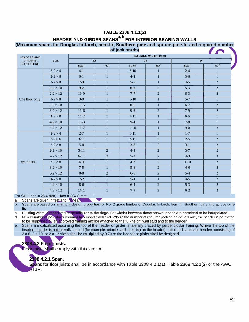
52
TABLE 2308.4.1.1(2)
HEADER AND GIRDER SPANSa, b
FOR INTERIOR BEARING WALLS (Maximum spans for Douglas fir-larch, hem-fir, Southern pine and spruce-pine-fir and required number
of jack studs)
HEADERS AND GIRDERS
SUPPORTING
SIZE
BUILDING WIDTHc (feet)
12 24 36
Spane NJd
Spane NJd
Spane NJd
One floor only
2-2 × 4 4-1 1 2-10 1 2-4 1
2-2 × 6 6-1 1 4-4 1 3-6 1
2-2 × 8 7-9 1 5-5 1 4-5 2
2-2 × 10 9-2 1 6-6 2 5-3 2
2-2 × 12 10-9 1 7-7 2 6-3 2
3-2 × 8 9-8 1 6-10 1 5-7 1
3-2 × 10 11-5 1 8-1 1 6-7 2
3-2 × 12 13-6 1 9-6 2 7-9 2
4-2 × 8 11-2 1 7-11 1 6-5 1
4-2 × 10 13-3 1 9-4 1 7-8 1
4-2 × 12 15-7 1 11-0 1 9-0 2
Two floors
2-2 × 4 2-7 1 1-11 1 1-7 1
2-2 × 6 3-11 1 2-11 2 2-5 2
2-2 × 8 5-0 1 3-8 2 3-1 2
2-2 × 10 5-11 2 4-4 2 3-7 2
2-2 × 12 6-11 2 5-2 2 4-3 3
3-2 × 8 6-3 1 4-7 2 3-10 2
3-2 × 10 7-5 1 5-6 2 4-6 2
3-2 × 12 8-8 2 6-5 2 5-4 2
4-2 × 8 7-2 1 5-4 1 4-5 2
4-2 × 10 8-6 1 6-4 2 5-3 2
4-2 × 12 10-1 1 7-5 2 6-2 2
For SI: 1 inch = 25.4 mm, 1 foot = 304.8 mm. a. Spans are given in feet and inches. b. Spans are based on minimum design properties for No. 2 grade lumber of Douglas fir-larch, hem-fir, Southern pine and spruce-pine
fir. c. Building width is measured perpendicular to the ridge. For widths between those shown, spans are permitted to be interpolated. d. NJ = Number of jack studs required to support each end. Where the number of required jack studs equals one, the header is permitted
to be supported by an approved framing anchor attached to the full-height wall stud and to the header. e. Spans are calculated assuming the top of the header or girder is laterally braced by perpendicular framing. Where the top of the
header or girder is not laterally braced (for example, cripple studs bearing on the header), tabulated spans for headers consisting of 2 × 8, 2 × 10, or 2 × 12 sizes shall be multiplied by 0.70 or the header or girder shall be designed.
2308.4.2 Floor joists. Floor joists shall comply with this section.
2308.4.2.1 Span. Spans for floor joists shall be in accordance with Table 2308.4.2.1(1), Table 2308.4.2.1(2) or the AWC STJR.
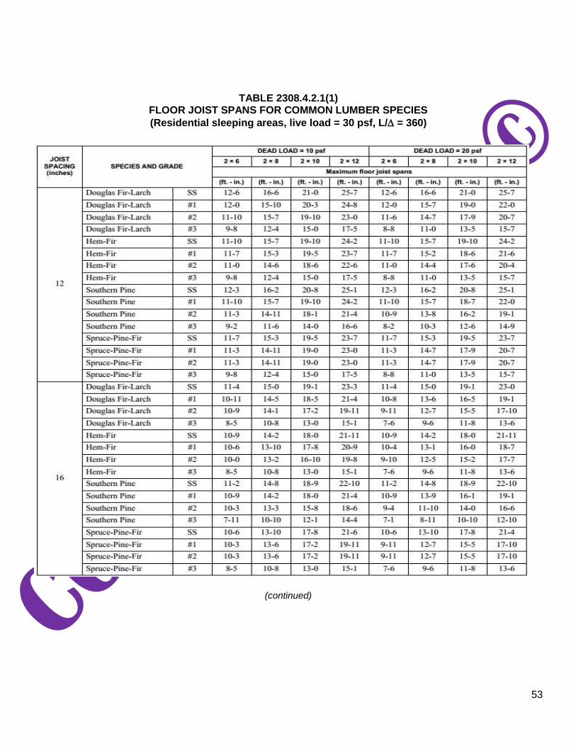
53
TABLE 2308.4.2.1(1) FLOOR JOIST SPANS FOR COMMON LUMBER SPECIES
(Residential sleeping areas, live load = 30 psf, L/ = 360)
(continued)

54
TABLE 2308.4.2.1(1)—continued FLOOR JOIST SPANS FOR COMMON LUMBER SPECIES
(Residential sleeping areas, live load = 30 psf, L/ = 360)
For SI: 1 inch = 25.4 mm, 1 foot = 304.8 mm, 1 pound per square foot = 0.0479 kPa. Note: Check sources for availability of lumber in lengths greater than 20 feet.

55
TABLE 2308.4.2.1(2) FLOOR JOIST SPANS FOR COMMON LUMBER SPECIES
(Residential living areas, live load = 40 psf, L/ = 360)
(continued)

56
TABLE 2308.4.2.1(2)—continued FLOOR JOIST SPANS FOR COMMON LUMBER SPECIES
(Residential living areas, live load = 40 psf, L/ = 360)
For SI: 1 inch = 25.4 mm, 1 foot = 304.8 mm, 1 pound per square foot = 0.0479 kPa. Note: Check sources for availability of lumber in lengths greater than 20 feet.
a. End bearing length shall be increased to 2 inches.
2308.4.2.2 Bearing.
The ends of each joist shall have not less than 11/2 inches (38 mm) of bearing on wood or metal, or not
less than 3 inches (76 mm) on masonry, except where supported on a 1-inch by 4-inch (25 mm by 102 mm) ribbon strip and nailed to the adjoining stud.
2308.4.2.3 Framing details. Joists shall be supported laterally at the ends and at each support by solid blocking except where the ends of the joists are nailed to a header, band or rim joist or to an adjoining stud or by other means.

57
Solid blocking shall be not less than 2 inches (51 mm) in thickness and the full depth of the joist. Joist framing from opposite sides of a beam, girder or partition shall be lapped not less than 3 inches (76 mm) or the opposing joists shall be tied together in an approved manner. Joists framing into the side of a wood girder shall be supported by framing anchors or on ledger strips not less than 2 inches by 2 inches (51 mm by 51 mm).
2308.4.2.4 Notches and holes. Notches on the ends of joists shall not exceed one-fourth the joist depth. Notches in the top or bottom of joists shall not exceed one-sixth the depth and shall not be located in the middle third of the span. Holes bored in joists shall not be within 2 inches (51 mm) of the top or bottom of the joist and the diameter of any such hole shall not exceed one-third the depth of the joist.
2308.4.3 Engineered wood products. Engineered wood products shall be installed in accordance with manufacturer’s recommendations. Cuts, notches and holes bored in trusses, structural composite lumber, structural glued-laminated members or I-joists are not permitted except where permitted by the manufacturer’s recommendations or where the effects of such alterations are specifically considered in the design of the member by a registered design professional.
2308.4.4 Framing around openings. Trimmer and header joists shall be doubled, or of lumber of equivalent cross section, where the span of the header exceeds 4 feet (1219 mm). The ends of header joists more than 6 feet (1829 mm) in length shall be supported by framing anchors or joist hangers unless bearing on a beam, partition or wall. Tail joists over 12 feet (3658 mm) in length shall be supported at the header by framing anchors or on ledger strips not less than 2 inches by 2 inches (51 mm by 51 mm).
2308.4.4.1 Openings in floor diaphragms in Seismic Design Categories B, C, D and E. Openings in horizontal diaphragms in Seismic Design Categories B, C, D and E with a dimension that is greater than 4 feet (1219 mm) shall be constructed with metal ties and blocking in accordance with this section and Figure 2308.4.4.1(1). Metal ties shall be not less than 0.058 inch [1.47 mm (16
galvanized gage)] in thickness by 11/2 inches (38 mm) in width and shall have a yield stress not less
than 33,000 psi (227 Mpa). Blocking shall extend not less than the dimension of the opening in the direction of the tie and blocking. Ties shall be attached to blocking in accordance with the manufacturer’s instructions but with not less than eight 16d common nails on each side of the header-joist intersection.
Openings in floor diaphragms in Seismic Design Categories D and E shall not have any dimension exceeding 50 percent of the distance between braced wall lines or an area greater than 25 percent of the area between orthogonal pairs of braced wall lines [see Figure 2308.4.4.1(2)]; or the portion of the structure containing the opening shall be designed in accordance with accepted engineering practice to resist the forces specified in Chapter 16, to the extent such irregular opening affects the performance of the conventional framing system.
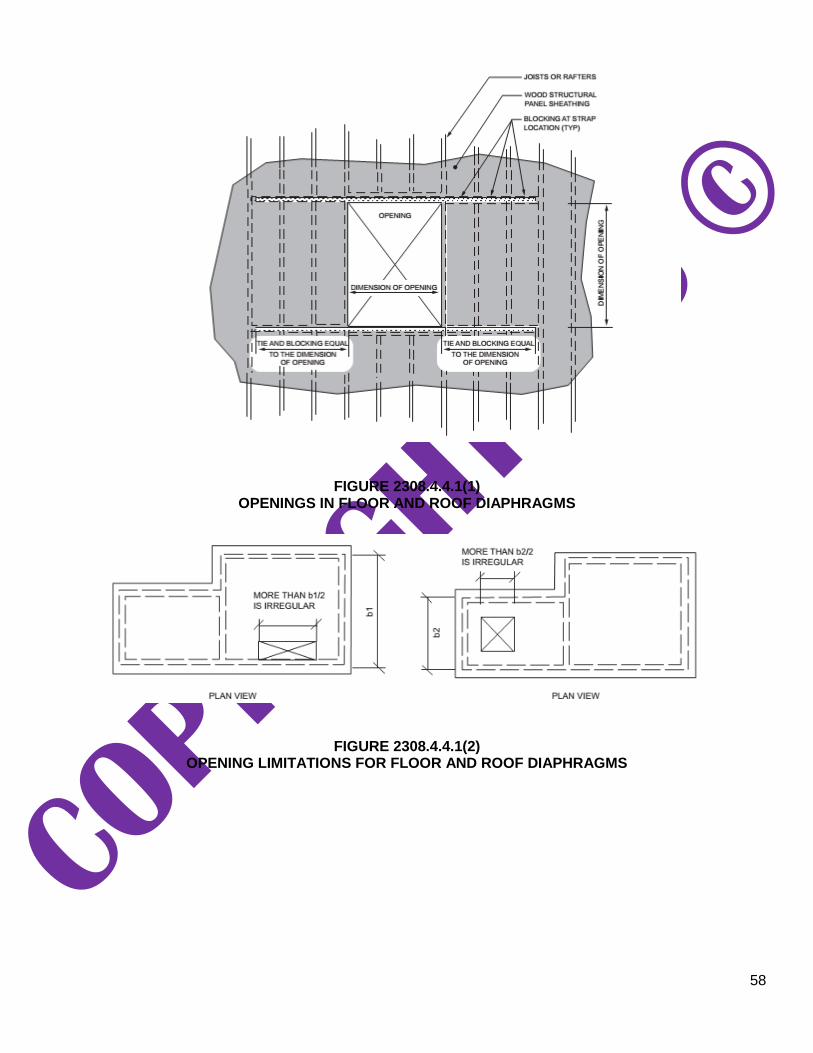
58
FIGURE 2308.4.4.1(1) OPENINGS IN FLOOR AND ROOF DIAPHRAGMS
FIGURE 2308.4.4.1(2) OPENING LIMITATIONS FOR FLOOR AND ROOF DIAPHRAGMS

59
2308.4.4.2 Vertical offsets in floor diaphragms in Seismic Design Categories D and E. In Seismic Design Categories D and E, portions of a floor level shall not be vertically offset such that the framing members on either side of the offset cannot be lapped or tied together in an approved manner in accordance with Figure 2308.4.4.2 unless the portion of the structure containing the irregular offset is designed in accordance with accepted engineering practice.
Exception: Framing supported directly by foundations need not be lapped or tied directly together.
FIGURE 2308.4.4.2 PORTIONS OF FLOOR LEVEL OFFSET VERTICALLY
2308.4.5 Joists supporting bearing partitions. Bearing partitions parallel to joists shall be supported on beams, girders, doubled joists, walls or other bearing partitions. Bearing partitions perpendicular to joists shall not be offset from supporting girders, walls or partitions more than the joist depth unless such joists are of sufficient size to carry the additional load.
2308.4.6 Lateral support. Floor and ceiling framing with a nominal depth-to-thickness ratio not less than 5 to 1 shall have one edge held in line for the entire span. Where the nominal depth-to-thickness ratio of the framing member exceeds 6 to 1, there shall be one line of bridging for each 8 feet (2438 mm) of span, unless both edges of the member are held in line. The bridging shall consist of not less than 1-inch by 3-inch (25 mm by 76 mm) lumber, double nailed at each end, or equivalent metal bracing of equal rigidity, full-depth solid blocking or other approved means. A line of bridging shall be required at supports where equivalent lateral support is not otherwise provided.
2308.4.7 Structural floor sheathing. Structural floor sheathing shall comply with the provisions of Section 2304.8.1.
2308.4.8 Under-floor ventilation. For under-floor ventilation, see Section 1202.4.
2308.4.9 Floor framing supporting braced wall panels. Where braced wall panels are supported by cantilevered floors or are set back from the floor joist support, the floor framing shall comply with Section 2308.6.7.
2308.4.10 Anchorage of exterior means of egress components in Seismic Design Categories D and E. Exterior egress balconies, exterior stairways and ramps and similar means of egress components in structures assigned to Seismic Design Category D or E shall be positively anchored to the primary

60
structure at not more than 8 feet (2438 mm) on center or shall be designed for lateral forces. Such attachment shall not be accomplished by use of toenails or nails subject to withdrawal.
2308.5 Wall construction. Walls of conventional light-frame construction shall be in accordance with this section.
2308.5.1 Stud size, height and spacing. The size, height and spacing of studs shall be in accordance with Table 2308.5.1.
Studs shall be continuous from a support at the sole plate to a support at the top plate to resist loads
perpendicular to the wall. The support shall be a foundation or floor, ceiling or roof diaphragm or shall be designed in accordance with accepted engineering practice.
Exception: Jack studs, trimmer studs and cripple studs at openings in walls that comply with Table 2308.4.1.1(1) or 2308.4.1.1(2).
TABLE 2308.5.1
SIZE, HEIGHT AND SPACING OF WOOD STUDSc
STUD SIZE (inches)
BEARING WALLS NONBEARING WALLS
Laterally unsupported
stud heighta
(feet)
Supporting roof and ceiling only
Supporting one floor, roof and
ceiling
Supporting two floors, roof and
ceiling
Laterally unsupported
stud heighta
(feet)
Spacing (inches)
Spacing (inches)
2 × 3b — — — — 10 16
2 × 4 10 24 16 — 14 24
3 × 4 10 24 24 16 14 24
2 × 5 10 24 24 — 16 24
2 × 6 10 24 24 16 20 24
For SI: 1 inch = 25.4 mm, 1 foot = 304.8 mm. a. Listed heights are distances between points of lateral support placed perpendicular to the plane of the wall. Increases in unsupported
height are permitted where justified by an analysis. b. Shall not be used in exterior walls. c. Utility-grade studs shall not be spaced more than 16 inches on center or support more than a roof and ceiling, or exceed 8 feet in
height for exterior walls and load-bearing walls or 10 feet for interior nonload-bearing walls.
2308.5.2 Framing details. Studs shall be placed with their wide dimension perpendicular to the wall. Not less than three studs shall be installed at each corner of an exterior wall.
Exceptions:
1. In interior nonbearing walls and partitions, studs are permitted to be set with the long dimension
parallel to the wall.
61
2. At corners, two studs are permitted, provided that wood spacers or backup cleats of 3/8-inch-thick
(9.5 mm) wood structural panel, 3/8-inch (9.5 mm) Type M “Exterior Glue” particleboard, 1-inch-
thick (25 mm) lumber or other approved devices that will serve as an adequate backing for the attachment of facing materials are used. Where fire-resistance ratings or shear values are involved, wood spacers, backup cleats or other devices shall not be used unless specifically approved for such use.
2308.5.3 Plates and sills. Studs shall have plates and sills in accordance with this section.
2308.5.3.1 Bottom plate or sill. Studs shall have full bearing on a plate or sill. Plates or sills shall be not less than 2 inches (51 mm) nominal in thickness and have a width not less than the width of the wall studs.
2308.5.3.2 Top plates. Bearing and exterior wall studs shall be capped with double top plates installed to provide overlapping at corners and at intersections with other partitions. End joints in double top plates shall be offset not less than 48 inches (1219 mm), and shall be nailed in accordance with Table 2304.10.2. Plates shall be a nominal 2 inches (51 mm) in depth and have a width not less than the width of the studs.
Exception: A single top plate is permitted, provided that the plate is adequately tied at corners and intersecting walls by not less than the equivalent of 3-inch by 6-inch (76 mm by 152 mm) by 0.036-inch-thick (0.914 mm) galvanized steel plate that is nailed to each wall or segment of wall by six 8d
[21/2” × 0.113” (64-mm by 2.87 mm)] box nails or equivalent on each side of the joint. For the butt-
joint splice between adjacent single top plates, not less than the equivalent of a 3-inch by 12-inch (76 mm by 304 mm) by 0.036-inch-thick (0.914 mm) galvanized steel plate that is nailed to each
wall or segment of wall by 12 8d [21/2-inch × 0.113-inch (64 mm by 2.87 mm)] box nails on each
side of the joint shall be required, provided that the rafters, joists or trusses are centered over the studs with a tolerance of not more than 1 inch (25 mm). The top plate shall not be required over headers that are in the same plane and in line with the upper surface of the adjacent top plates and are tied to adjacent wall sections as required for the butt joint splice between adjacent single top plates.
Where bearing studs are spaced at 24-inch (610 mm) intervals, top plates are less than two 2-inch
by 6-inch (51 mm by 152 mm) or two 3-inch by 4-inch (76 mm by 102 mm) members and the floor joists, floor trusses or roof trusses that they support are spaced at more than 16-inch (406 mm) intervals, such joists or trusses shall bear within 5 inches (127 mm) of the studs beneath or a third plate shall be installed.
2308.5.4 Nonload-bearing walls and partitions. In nonload-bearing walls and partitions, that are not part of a braced wall panel, studs shall be spaced not more than 24 inches (610 mm) on center. In interior nonload-bearing walls and partitions, studs are permitted to be set with the long dimension parallel to the wall. Where studs are set with the long dimensions parallel to the wall, use of utility grade lumber or studs exceeding 10 feet (3048 mm) is not permitted. Interior nonload-bearing partitions shall be capped with not less than a single top plate installed to provide overlapping at corners and at intersections with other walls and partitions. The plate shall be continuously tied at joints by solid blocking not less than 16 inches (406 mm) in length and equal in size to
the plate or by 1/2-inch by 1
1/2-inch (12.7 mm by 38 mm) metal ties with spliced sections fastened with two
16d nails on each side of the joint.

62
2308.5.5 Openings in walls and partitions. Openings in exterior and interior walls and partitions shall comply with Sections 2308.5.5.1 through 2308.5.5.3.
2308.5.5.1 Openings in exterior bearing walls. Headers shall be provided over each opening in exterior bearing walls. The size and spans in Table 2308.4.1.1(1) are permitted to be used for one- and two-family dwellings. Headers for other buildings shall be designed in accordance with Section 2302.1, Item 1 or 2. Headers of two or more pieces of nominal 2-inch (51 mm) framing lumber set on edge shall be permitted in accordance with Table 2308.4.1.1(1) and nailed together in accordance with Table 2304.10.2 or of solid lumber of equivalent size.
Single-member headers of nominal 2-inch (51 mm) thickness shall be framed with a single flat 2-inch-
nominal (51 mm) member or wall plate not less in width than the wall studs on the top and bottom of the header in accordance with Figures 2308.5.5.1(1) and 2308.5.5.1(2) and face nailed to the top and bottom of the header with 10d box nails [3 inches × 0.128 inches (76 mm × 3.3 mm)] spaced 12 inches (305 mm) on center.
Wall studs shall support the ends of the header in accordance with Table 2308.4.1.1(1). Each end of
a lintel or header shall have a bearing length of not less than 11/2 inches (38 mm) for the full width of the
lintel.
FIGURE 2308.5.5.1(1) SINGLE-MEMBER HEADER IN EXTERIOR BEARING WALL

63
FIGURE 2308.5.5.1(2) ALTERNATIVE SINGLE-MEMBER HEADER WITHOUT CRIPPLE
2308.5.5.2 Openings in interior bearing partitions. Headers shall be provided over each opening in interior bearing partitions as required in Section 2308.5.5.1. The spans in Table 2308.4.1.1(2) are permitted to be used. Wall studs shall support the ends of the header in accordance with Table 2308.4.1.1(1) or 2308.4.1.1(2), as applicable.
2308.5.5.3 Openings in interior nonbearing partitions. Openings in nonbearing partitions are permitted to be framed with single studs and headers. Each end
of a lintel or header shall have a bearing length of not less than 11/2 inches (38 mm) for the full width of
the lintel.
2308.5.6 Cripple walls. Foundation cripple walls shall be framed of studs that are not less than the size of the studding above. Exterior cripple wall studs shall be not less than 14 inches (356 mm) in length, or shall be framed of solid blocking. Where exceeding 4 feet (1219 mm) in height, such walls shall be framed of studs having the size required for an additional story. See Section 2308.6.6 for cripple wall bracing.
2308.5.7 Bridging. Unless covered by interior or exterior wall coverings or sheathing meeting the minimum requirements of this code, stud partitions or walls with studs having a height-to-least-thickness ratio exceeding 50 shall have bridging that is not less than 2 inches (51 mm) in thickness and of the same width as the studs fitted snugly and nailed thereto to provide adequate lateral support. Bridging shall be placed in every stud cavity and at a frequency such that studs so braced shall not have a height-to-least-thickness ratio exceeding 50 with the height of the stud measured between horizontal framing and bridging or between bridging, whichever is greater.
2308.5.8 Pipes in walls. Stud partitions containing plumbing, heating or other pipes shall be framed and the joists underneath spaced to provide proper clearance for the piping. Where a partition containing piping runs parallel to the floor joists, the joists underneath such partitions shall be doubled and spaced to permit the passage of pipes and shall be bridged. Where plumbing, heating or other pipes are placed in, or partly in, a partition, necessitating the cutting of the soles or plates, a metal tie not less than 0.058 inch (1.47 mm) (16
galvanized gage) and 11/2 inches (38 mm) in width shall be fastened to each plate across and to each side
of the opening with not less than six 16d nails.

64
2308.5.9 Cutting and notching. In exterior walls and bearing partitions, a wood stud shall not be cut or notched in excess of 25 percent of its depth. In nonbearing partitions that do not support loads other than the weight of the partition, a stud shall not be cut or notched in excess of 40 percent of its depth.
2308.5.10 Bored holes. The diameter of bored holes in wood studs shall not exceed 40 percent of the stud depth. The diameter of bored holes in wood studs shall not exceed 60 percent of the stud depth in nonbearing partitions. The diameter of bored holes in wood studs shall not exceed 60 percent of the stud depth in any wall where each stud is doubled, provided that not more than two such successive doubled studs are so bored. The
edge of the bored hole shall not be closer than 5/8 inch (15.9 mm) to the edge of the stud. Bored holes shall
not be located at the same section of stud as a cut or notch.
2308.5.11 Exterior wall sheathing. Except where stucco construction that complies with Section 2510 is installed, the outside of exterior walls, including gables, of enclosed buildings shall be sheathed with one of the materials of the nominal thickness specified in Table 2308.5.11 with fasteners in accordance with the requirements of Section 2304.10 or fasteners designed in accordance with accepted engineering practice. Alternatively, sheathing materials and fasteners complying with Section 2304.6 shall be permitted.
TABLE 2308.5.11 MINIMUM THICKNESS OF WALL SHEATHING
SHEATHING TYPE MINIMUM THICKNESS MAXIMUM WALL STUD SPACING
Diagonal wood boards 5/8 inch
24 inches on center
Structural fiberboard 1/2 inch
16 inches on center
Wood structural panel In accordance with Tables 2308.6.3(2) and
2308.6.3(3) —
M-S “Exterior Glue” and M-2 “Exterior Glue” particleboard
In accordance with Section 2306.3 and Table 2308.6.3(4)
—
Gypsum sheathing 1/2 inch
16 inches on center
Reinforced cement mortar 1 inch 24 inches on
center
Hardboard panel siding In accordance with Table 2308.6.3(5) —
For SI: 1 inch = 25.4 mm.
2308.6 Wall bracing. Buildings shall be provided with exterior and interior braced wall lines as described in Sections 2308.6.1 through 2308.6.10.2.
2308.6.1 Braced wall lines. For the purpose of determining the amount and location of bracing required along each story level of a building, braced wall lines shall be designated as straight lines through the building plan in both the longitudinal and transverse direction and placed in accordance with Table 2308.6.1 and Figure 2308.6.1.
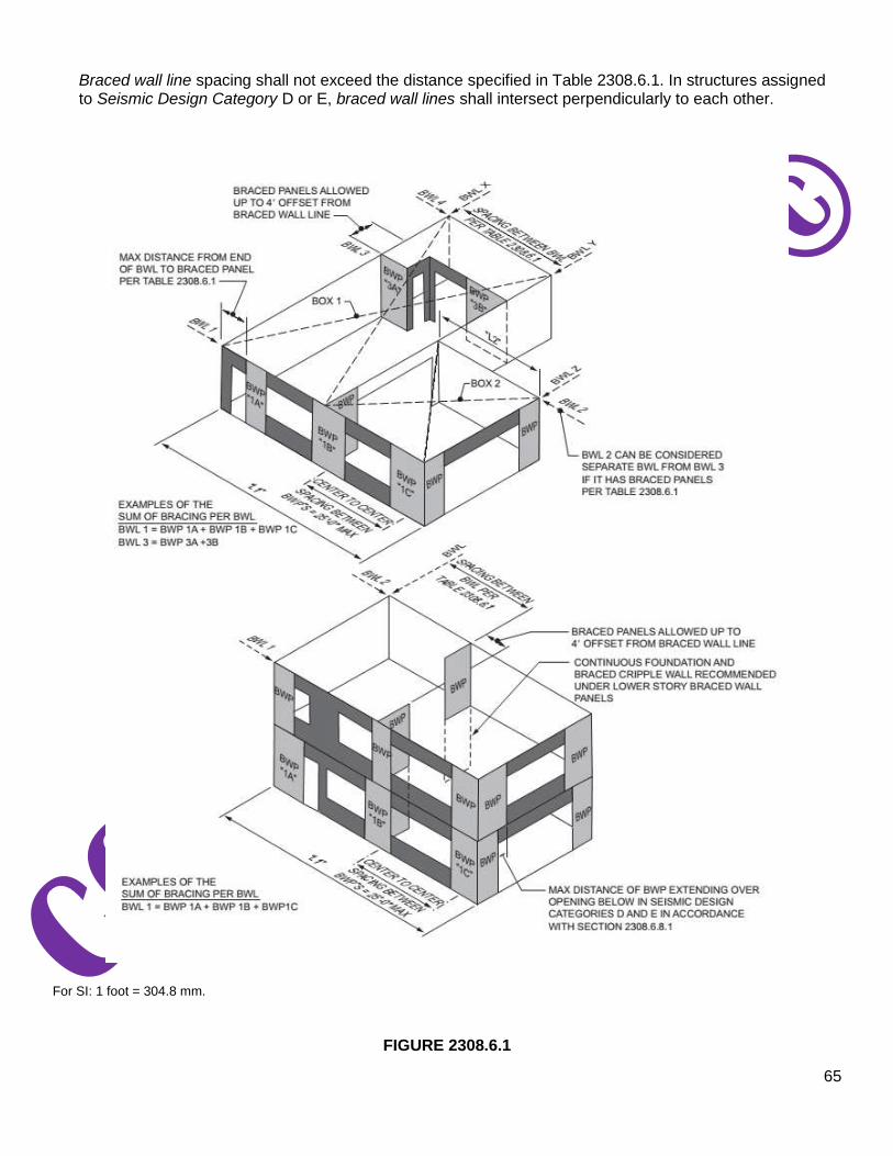
65
Braced wall line spacing shall not exceed the distance specified in Table 2308.6.1. In structures assigned to Seismic Design Category D or E, braced wall lines shall intersect perpendicularly to each other.
For SI: 1 foot = 304.8 mm.
FIGURE 2308.6.1

66
BASIC COMPONENTS OF THE LATERAL BRACING SYSTEM
TABLE 2308.6.1
WALL BRACING REQUIREMENTSa
For SI: 1 inch = 25.4 mm, 1 foot = 304.8 mm. NP = Not Permitted. a. This table specifies minimum requirements for braced wall panels along interior or exterior braced wall lines. b. See Section 2308.6.3 for full description of bracing methods. c. For Method GB, gypsum wallboard applied to framing supports that are spaced at 16 inches on center. d. The required lengths shall be doubled for gypsum board applied to only one face of a braced wall panel. e. Percentage shown represents the minimum amount of bracing required along the building length (or wall length if the structure has
an irregular shape).

67
2308.6.2 Braced wall panels. Braced wall panels shall be placed along braced wall lines in accordance with Table 2308.6.1 and Figure 2308.6.1 and as specified in Table 2308.6.3(1). A braced wall panel shall be located at each end of the braced wall line and at the corners of intersecting braced wall lines or shall begin within the maximum distance from the end of the braced wall line in accordance with Table 2308.6.1. Braced wall panels in a braced wall line shall not be offset from each other by more than 4 feet (1219 mm). Braced wall panels shall be clearly indicated on the plans.
2308.6.3 Braced wall panel methods. Construction of braced wall panels shall be by one or a combination of the methods in Table 2308.6.3(1). Braced wall panel length shall be in accordance with Section 2308.6.4 or 2308.6.5.

68
TABLE 2308.6.3(1) BRACING METHODS
METHODS, MATERIAL
MINIMUM THICKNESS
FIGURE CONNECTION CRITERIAa
Fasteners Spacing
LIBa
Let-in-bracing
1″ × 4″ wood or approved metal straps attached at 45° to 60° angles to studs at maximum of 16″ o.c.
Table 2304.10.2 Wood: per stud plus top and
bottom plates
Metal strap: installed in accor- dance with manufacturer’s
recommendations
Metal strap: installed in accordance with manufac- turer’s
recommendations
DWB
Diagonal wood boards
3/ ″ thick (1″ nominal) × 4
6″ minimum width to studs at maximum of 24″ o.c.
Table 2304.10.2
Per stud
WSP
Wood structural panel
3/ ″ in accordance with
8
Table 2308.6.3(2) or 2308.6.3(3)
Table 2304.10.2
6″ edges 12″ field
SFB
Structural fiber- board sheathing
1/ ″ in accordance with
2
Table 2304.10.2 to studs at maximum 16″ o.c.
Table 2304.10.2
3″ edges 6″ field
GB
Gypsum board (Double sided)
1/ ″ or 5/ ″ by not less than
2 8
4′ wide to studs at maximum of 24” o.c.
Section 2506.2 for exterior and inte- rior sheathing: 5d annual ringed
cooler nails (15/ ″ × 0.086″) or 11/ ″ 8 4
screws (Type W or S) for 1/ ″ 2
gypsum board or 15/ ″ screws (Type 8
W or S) for 5/ ″ gypsum board 8
For all braced wall panel locations: 7″ o.c. along panel edges (including
top and bottom plates) and 7” o.c. in the field
PBS
Particleboard sheathing
3/ ″ or 1/ ″ in accordance 8 2
with Table 2308.6.3(4) to studs at maximum of 16″ o.c.
6d common (2″ long × 0.113″ dia.) nails for 3/ ″ thick sheathing or 8d 8 common (21/ ″ long × 0.131″ dia.)
2
nails for 1/ ″ thick sheathing 2
3″ edges 6″ field
PCP
Portland cement plaster
Section 2510 to studs at maximum of 16″ o.c.
11/ ″ long, 11 gage, 0.120" dia.,
2 7/ ″ dia. head nails or 7/ ″ long,
16 8
16 gage staples
6″ o.c. on all framing members
HPS
Hardboard panel siding
7/ ″ in accordance with 16
Table 2308.6.3(5)
Table 2304.10.2
4″ edges 8″ field
ABW
Alternate braced wall
3/ ″
8
Figure 2308.6.5.1 and Section 2308.6.5.1
Figure 2308.6.5.1
PFH
Portal frame with hold-downs
3/ ″
8
Figure 2308.6.5.2 and Section 2308.6.5.2
Figure 2308.6.5.2
For SI: 1 foot = 304.8 mm, 1 degree = 0.01745 rad. a. Method LIB shall have gypsum board fastened to one or more side(s) with nails or screws

69
TABLE 2308.6.3(2) EXPOSED PLYWOOD PANEL SIDING
MINIMUM THICKNESSa
(inch)
MINIMUM NUMBER OF PLIES
STUD SPACING (inches)
Plywood siding applied directly to studs or over sheathing
3/8 3 16
b
1/2 4 24
For SI: 1 inch = 25.4 mm. a. Thickness of grooved panels is measured at bottom of grooves. b. Spans are permitted to be 24 inches if plywood siding applied with face grain perpendicular to studs or over one of the following: 1-
inch board sheathing; 7/16
- inch wood structural panel sheathing; or 3/8-inch wood structural panel sheathing with strength axis
(which is the long direction of the panel unless otherwise marked) of sheathing perpendicular to studs.
TABLE 2308.6.3(3)
WOOD STRUCTURAL PANEL WALL SHEATHINGb
(Not exposed to the weather, strength axis parallel or perpendicular to studs except as indicated)
MINIMUM THICKNESS
(inch)
PANEL SPAN RATING
STUD SPACING (inches)
Siding nailed to studs
Nailable sheathing
Sheathing parallel to studs
Sheathing perpendicular to studs
3/8,
15/32
, 1/2
16/0, 20/0, 24/0, 32/16
Wall—24 o.c. 24 16 24
7/16
, 15
/32
, 1/2
24/0, 24/16, 32/16
Wall—24 o.c. 24 24
a 24
For SI: 1 inch = 25.4 mm. a. Plywood shall consist of four or more plies. b. Blocking of horizontal joints shall not be required except as specified in Section 2308.6.4.
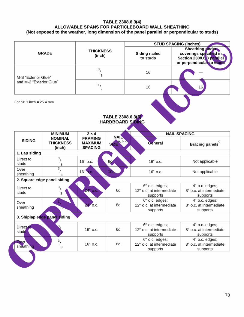
70
TABLE 2308.6.3(4) ALLOWABLE SPANS FOR PARTICLEBOARD WALL SHEATHING
(Not exposed to the weather, long dimension of the panel parallel or perpendicular to studs)
GRADE THICKNESS
(inch)
STUD SPACING (inches)
Siding nailed to studs
Sheathing under coverings specified in
Section 2308.6.3 parallel or perpendicular to studs
M-S “Exterior Glue” and M-2 “Exterior Glue”
3/8 16 —
1/2 16 16
For SI: 1 inch = 25.4 mm.
TABLE 2308.6.3(5) HARDBOARD SIDING
SIDING
MINIMUM NOMINAL
THICKNESS (inch)
2 × 4 FRAMING MAXIMUM SPACING
NAIL
SIZEa, b, d
NAIL SPACING
General Bracing panelsc
1. Lap siding
Direct to studs
3/8 16 o.c. 8d 16 o.c. Not applicable
Over sheathing
3/8 16 o.c. 10d 16 o.c. Not applicable
2. Square edge panel siding
Direct to studs
3/8 24 o.c. 6d
6 o.c. edges;
12 o.c. at intermediate supports
4 o.c. edges;
8 o.c. at intermediate supports
Over sheathing
3/8 24 o.c. 8d
6 o.c. edges;
12 o.c. at intermediate supports
4 o.c. edges;
8 o.c. at intermediate supports
3. Shiplap edge panel siding
Direct to studs
3/8 16 o.c. 6d
6 o.c. edges;
12 o.c. at intermediate supports
4 o.c. edges;
8 o.c. at intermediate supports
Over sheathing
3/8 16 o.c. 8d
6 o.c. edges;
12 o.c. at intermediate supports
4 o.c. edges;
8 o.c. at intermediate supports

71
For SI: 1 inch = 25.4 mm. a. Nails shall be corrosion resistant. b. Minimum acceptable nail dimensions:
Panel Siding (inch) Lap Siding (inch)
Shank diameter 0.092 0.099 Head diameter 0.225 0.240
c. Where used to comply with Section 2308.6.
d. Nail length must accommodate the sheathing and penetrate framing 11/2 inches.
2308.6.4 Braced wall panel construction. For Methods DWB, WSP, SFB, PBS, PCP and HPS, each panel must be not less than 48 inches (1219 mm) in length, covering three stud spaces where studs are spaced 16 inches (406 mm) on center and covering two stud spaces where studs are spaced 24 inches (610 mm) on center. Braced wall panels less than 48 inches (1219 mm) in length shall not contribute toward the amount of required bracing. Braced wall panels that are longer than the required length shall be credited for their actual length. For Method GB, each panel must be not less than 96 inches (2438 mm) in length where applied to one side of the studs or 48 inches (1219 mm) in length where applied to both sides.
Vertical joints of panel sheathing shall occur over studs and adjacent panel joints shall be nailed to
common framing members. Horizontal joints shall occur over blocking or other framing equal in size to the studding except where waived by the installation requirements for the specific sheathing materials. Sole plates shall be nailed to the floor framing in accordance with Section 2308.6.7 and top plates shall be connected to the framing above in accordance with Section 2308.6.7.2. Where joists are perpendicular to braced wall lines above, blocking shall be provided under and in line with the braced wall panels.
2308.6.5 Alternative bracing. An alternate braced wall (ABW) or a portal frame with hold-downs (PFH) described in this section is permitted to substitute for a 48-inch (1219 mm) braced wall panel of Method DWB, WSP, SFB, PBS, PCP or HPS. For Method GB, each 96-inch (2438 mm) section (applied to one face) or 48-inch (1219 mm) section (applied to both faces) or portion thereof required by Table 2308.6.1 is permitted to be replaced by one panel constructed in accordance with Method ABW or PFH.
2308.6.5.1 Alternate braced wall (ABW). An ABW shall be constructed in accordance with this section and Figure 2308.6.5.1. In one-story buildings, each panel shall have a length of not less than 2 feet 8 inches (813 mm) and a height of not
more than 10 feet (3048 mm). Each panel shall be sheathed on one face with 3/8-inch (3.2 mm)
minimum-thickness wood structural panel sheathing nailed with 8d common or galvanized box nails in accordance with Table 2304.10.2 and blocked at wood structural panel edges. Two anchor bolts installed in accordance with Section 2308.3.1 shall be provided in each panel. Anchor bolts shall be placed at each panel outside quarter points. Each panel end stud shall have a hold-down device fastened to the foundation, capable of providing an approved uplift capacity of not less than 1,800 pounds (8006 N). The hold-down device shall be installed in accordance with the manufacturer’s recommendations. The ABW shall be supported directly on a foundation or on floor framing supported directly on a foundation that is continuous across the entire length of the braced wall line. This foundation shall be reinforced with not less than one No. 4 bar top and bottom. Where the continuous foundation is required to have a depth greater than 12 inches (305 mm), a minimum 12-inch by 12-inch (305 mm by 305 mm) continuous footing or turned-down slab edge is permitted at door openings in the braced wall line. This continuous footing or turned-down slab edge shall be reinforced with not less than one No. 4 bar top and bottom. This reinforcement shall be lapped 15 inches (381 mm) with the reinforcement required in the continuous foundation located directly under the braced wall line.

72
Where the ABW is installed at the first story of two-story buildings, the wood structural panel
sheathing shall be provided on both faces, three anchor bolts shall be placed at one-quarter points and tie-down device uplift capacity shall be not less than 3,000 pounds (13 344 N).
For SI:1 inch = 25.4 mm, 1 foot = 304.8 mm.
FIGURE 2308.6.5.1 ALTERNATE BRACED WALL PANEL (ABW)
2308.6.5.2 Portal frame with hold-downs (PFH). A PFH shall be constructed in accordance with this section and Figure 2308.6.5.2. The adjacent door or window opening shall have a full-length header.
In one-story buildings, each panel shall have a length of not less than 16 inches (406 mm) and a
height of not more than 10 feet (3048 mm). Each panel shall be sheathed on one face with a single layer
of 3/8-inch (9.5 mm) minimum-thickness wood structural panel sheathing nailed with 8d common or
galvanized box nails in accordance with Figure 2308.6.5.2. The wood structural panel sheathing shall extend up over the solid sawn or glued-laminated header and shall be nailed in accordance with Figure 2308.6.5.2. A built-up header consisting of not fewer than two 2-inch by 12-inch (51 mm by 305 mm) boards, fastened in accordance with Item 24 of Table 2304.10.2 shall be permitted to be used. A spacer, if used, shall be placed on the side of the built-up beam opposite the wood structural panel sheathing. The header shall extend between the inside faces of the first full-length outer studs of each panel. The clear span of the header between the inner studs of each panel shall be not less than 6 feet (1829 mm) and not more than 18 feet (5486 mm) in length. A strap with an uplift capacity of not less than 1,000 pounds (4,400 N) shall fasten the header to the inner studs opposite the sheathing. One anchor bolt not
less than 5/8 inch (15.9 mm) diameter and installed in accordance with Section 2308.3.1 shall be provided
in the center of each sill plate. The studs at each end of the panel shall have a hold-down device fastened to the foundation with an uplift capacity of not less than 3,500 pounds (15 570 N).

73
Where a panel is located on one side of the opening, the header shall extend between the inside face of the first full-length stud of the panel and the bearing studs at the other end of the opening. A strap with an uplift capacity of not less than 1,000 pounds (4400 N) shall fasten the header to the bearing studs. The bearing studs shall have a hold-down device fastened to the foundation with an uplift capacity of not less than 1,000 pounds (4400 N). The hold-down devices shall be an embedded strap type, installed in accordance with the manufacturer’s recommendations. The PFH panels shall be supported directly on a foundation that is continuous across the entire length of the braced wall line. This foundation shall be reinforced with not less than one No. 4 bar top and bottom. Where the continuous foundation is required to have a depth greater than 12 inches (305 mm), a minimum 12-inch by 12-inch (305 mm by 305 mm) continuous footing or turned-down slab edge is permitted at door openings in the braced wall line. This continuous footing or turned-down slab edge shall be reinforced with not less than one No. 4 bar top and bottom. This reinforcement shall be lapped not less than 15 inches (381 mm) with the reinforcement required in the continuous foundation located directly under the braced wall line.
Where a PFH is installed at the first story of two-story buildings, each panel shall have a length of not
less than 24 inches (610 mm).
For SI:1 inch = 25.4 mm, 1 foot = 304.8 mm, 1 pound = 4.448 N.
FIGURE 2308.6.5.2 PORTAL FRAME WITH HOLD-DOWNS (PFH)
2308.6.6 Cripple wall bracing. Cripple walls shall be braced in accordance with Section 2308.6.6.1 or 2308.6.6.2.

74
2308.6.6.1 Cripple wall bracing in Seismic Design Categories A, B and C. For the purposes of this section, cripple walls in Seismic Design Categories A, B and C having a stud height exceeding 14 inches (356 mm) shall be considered to be a story and shall be braced in accordance with Table 2308.6.1. Spacing of edge nailing for required cripple wall bracing shall not exceed 6 inches (152 mm) on center along the foundation plate and the top plate of the cripple wall. Nail size, nail spacing for field nailing and more restrictive boundary nailing requirements shall be as required elsewhere in the code for the specific bracing material used.
2308.6.6.2 Cripple wall bracing in Seismic Design Categories D and E. For the purposes of this section, cripple walls in Seismic Design Categories D and E shall not have a stud height exceeding 14 inches (356 mm), and studs shall be solid blocked in accordance with Section 2308.5.6 for the full dwelling perimeter and for the full length of interior braced walls lines supported on foundations, excepting ventilation and access openings.
2308.6.7 Connections of braced wall panels. Braced wall panel joints shall occur over studs or blocking. Braced wall panels shall be fastened to studs, top and bottom plates and at panel edges. Braced wall panels shall be applied to nominal 2-inch-wide
[actual 11/2-inch (38 mm)] or larger stud framing.
2308.6.7.1 Bottom plate connection. Braced wall line bottom plates shall be connected to joists or full-depth blocking below in accordance with Table 2304.10.2, or to foundations in accordance with Section 2308.6.7.3.
2308.6.7.2 Top plate connection. Where joists or rafters are used, braced wall line top plates shall be fastened over the full length of the braced wall line to joists, rafters, rim boards or full-depth blocking above in accordance with Table 2304.10.2, as applicable, based on the orientation of the joists or rafters to the braced wall line. Blocking shall be not less than 2 inches (51 mm) in nominal thickness and shall be fastened to the braced wall line top plate as specified in Table 2304.10.2. Notching or drilling of holes in blocking in accordance with the requirements of Section 2308.4.2.4 or 2308.7.4 shall be permitted.
At exterior gable end walls, braced wall panel sheathing in the top story shall be extended and
fastened to the roof framing where the spacing between parallel exterior braced wall lines is greater than 50 feet (15 240 mm).
Where roof trusses are used and are installed perpendicular to an exterior braced wall line, lateral
forces shall be transferred from the roof diaphragm to the braced wall over the full length of the braced wall line by blocking of the ends of the trusses or by other approved methods providing equivalent lateral force transfer. Blocking shall be not less than 2 inches (51 mm) in nominal thickness and equal to the depth of the truss at the wall line and shall be fastened to the braced wall line top plate as specified in Table 2304.10.2. Notching or drilling of holes in blocking in accordance with the requirements of Section 2308.4.2.4 or 2308.7.4 shall be permitted.
Exception: Where the roof sheathing is greater than 91/4 inches (235 mm) above the top plate,
solid blocking is not required where the framing members are connected using one of the following methods:
1. In accordance with Figure 2308.6.7.2(1).
2. In accordance with Figure 2308.6.7.2(2).

75
3. Full-height engineered blocking panels designed for values listed in AWC WFCM.
4. A design in accordance with accepted engineering methods.
For SI:1 foot = 304.8 mm. a. Methods of bracing shall be as described in Table 2308.6.3(1) DWB, WSP, SFB, GB, PBS, PCP or HPS.
FIGURE 2308.6.7.2(1) BRACED WALL LINE TOP PLATE CONNECTION

76
For SI:1 foot = 304.8 mm. a. Methods of bracing shall be as described in Table 2308.6.3(1) DWB, WSP, SFB, GB, PBS, PCP or HPS
FIGURE 2308.6.7.2(2) BRACED WALL PANEL TOP PLATE CONNECTION
2308.6.7.3 Sill anchorage. Where foundations are required by Section 2308.6.8, braced wall line sills shall be anchored to concrete or masonry foundations. Such anchorage shall conform to the requirements of Section 2308.3. The anchors shall be distributed along the length of the braced wall line. Other anchorage devices having equivalent capacity are permitted.
2308.6.7.4 Anchorage to all-wood foundations. Where all-wood foundations are used, the force transfer from the braced wall lines shall be determined based on calculation and shall have a capacity that is not less than the connections required by Section 2308.3.
2308.6.8 Braced wall line and diaphragm support. Braced wall lines and floor and roof diaphragms shall be supported in accordance with this section.
2308.6.8.1 Foundation requirements. Braced wall lines shall be supported by continuous foundations.
Exception: For structures with a maximum plan dimension not more than 50 feet (15 240 mm), continuous foundations are required at exterior walls only.
For structures in Seismic Design Categories D and E, exterior braced wall panels shall be in the same
plane vertically with the foundation or the portion of the structure containing the offset shall be designed in accordance with accepted engineering practice and Section 2308.1.1.
77
Exceptions:
1. Exterior braced wall panels shall be permitted to be located not more than 4 feet (1219 mm)
from the foundation below where supported by a floor constructed in accordance with all of the following:
1.1. Cantilevers or setbacks shall not exceed four times the nominal depth of the floor
joists.
1.2. Floor joists shall be 2 inches by 10 inches (51 mm by 254 mm) or larger and spaced
not more than 16 inches (406 mm) on center.
1.3. The ratio of the back span to the cantilever shall be not less than 2 to 1.
1.4. Floor joists at ends of braced wall panels shall be doubled.
1.5. A continuous rim joist shall be connected to the ends of cantilevered joists. The rim
joist is permitted to be spliced using a metal tie not less than 0.058 inch (1.47 mm)
(16 galvanized gage) and 11/2 inches (38 mm) in width fastened with six 16d
common nails on each side. The metal tie shall have a yield stress not less than 33,000 psi (227 MPa).
1.6. Joists at setbacks or the end of cantilevered joists shall not carry gravity loads from
more than a single story having uniform wall and roof loads nor carry the reactions from headers having a span of 8 feet (2438 mm) or more.
2. The end of a required braced wall panel shall be allowed to extend not more than 1 foot (305
mm) over an opening in the wall below. This requirement is applicable to braced wall panels offset in plane and braced wall panels offset out of plane as permitted by Exception 1. Braced wall panels are permitted to extend over an opening not more than 8 feet (2438 mm) in width where the header is a 4-inch by 12-inch (102 mm by 305 mm) or larger member.
2308.6.8.2 Floor and roof diaphragm support in Seismic Design Categories D and E. In structures assigned to Seismic Design Categories D or E, floor and roof diaphragms shall be laterally supported by braced wall lines on all edges and connected in accordance with Section 2308.6.7 [see Figure 2308.6.8.2(1)].
Exception: Portions of roofs or floors that do not support braced wall panels above are permitted to extend up to 6 feet (1829 mm) beyond a braced wall line [see Figure 2308.6.8.2(2)] provided that the framing members are connected to the braced wall line below in accordance with Section 2308.6.7.
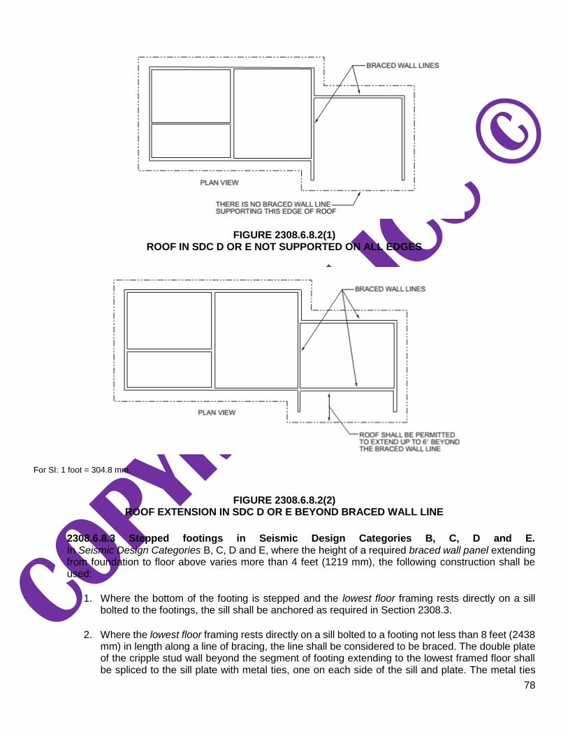
78
FIGURE 2308.6.8.2(1) ROOF IN SDC D OR E NOT SUPPORTED ON ALL EDGES
For SI: 1 foot = 304.8 mm.
FIGURE 2308.6.8.2(2) ROOF EXTENSION IN SDC D OR E BEYOND BRACED WALL LINE
2308.6.8.3 Stepped footings in Seismic Design Categories B, C, D and E. In Seismic Design Categories B, C, D and E, where the height of a required braced wall panel extending from foundation to floor above varies more than 4 feet (1219 mm), the following construction shall be used:
1. Where the bottom of the footing is stepped and the lowest floor framing rests directly on a sill
bolted to the footings, the sill shall be anchored as required in Section 2308.3.
2. Where the lowest floor framing rests directly on a sill bolted to a footing not less than 8 feet (2438
mm) in length along a line of bracing, the line shall be considered to be braced. The double plate of the cripple stud wall beyond the segment of footing extending to the lowest framed floor shall be spliced to the sill plate with metal ties, one on each side of the sill and plate. The metal ties

79
shall be not less than 0.058 inch [1.47 mm (16 galvanized gage)] by 11/2 inches (38 mm) in width
by 48 inches (1219 mm) with eight 16d common nails on each side of the splice location (see Figure 2308.6.8.3). The metal tie shall have a yield stress not less than 33,000 pounds per square inch (psi) (227 MPa).
3. Where cripple walls occur between the top of the footing and the lowest floor framing, the bracing
requirements for a story shall apply.
For SI:1 inch = 25.4 mm, 1 foot = 304.8 mm.
FIGURE 2308.6.8.3 STEPPED FOOTING CONNECTION DETAILS
2308.6.9 Attachment of sheathing. Fastening of braced wall panel sheathing shall be not less than that prescribed in Tables 2308.6.1 and 2304.10.2. Wall sheathing shall not be attached to framing members by adhesives.
2308.6.10 Limitations of concrete or masonry veneer. Concrete or masonry veneer shall comply with Chapter 14 and this section.
2308.6.10.1 Limitations of concrete or masonry veneer in Seismic Design Category B or C. In Seismic Design Categories B and C, concrete or masonry walls and stone or masonry veneer shall not extend above a basement.
Exceptions:
1. In structures assigned to Seismic Design Category B, stone and masonry veneer is permitted
to be used in the first two stories above grade plane or the first three stories above grade plane where the lowest story has concrete or masonry walls, provided that wood structural panel wall bracing is used and the length of bracing provided is one and one-half times the required length specified in Table 2308.6.1.
2. Stone and masonry veneer is permitted to be used in the first story above grade plane or the
first two stories above grade plane where the lowest story has concrete or masonry walls.
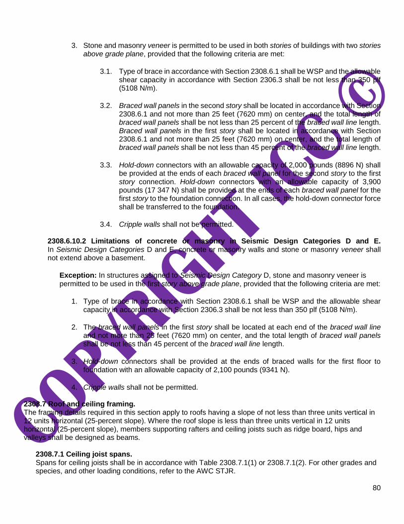
80
3. Stone and masonry veneer is permitted to be used in both stories of buildings with two stories
above grade plane, provided that the following criteria are met:
3.1. Type of brace in accordance with Section 2308.6.1 shall be WSP and the allowable
shear capacity in accordance with Section 2306.3 shall be not less than 350 plf (5108 N/m).
3.2. Braced wall panels in the second story shall be located in accordance with Section
2308.6.1 and not more than 25 feet (7620 mm) on center, and the total length of braced wall panels shall be not less than 25 percent of the braced wall line length. Braced wall panels in the first story shall be located in accordance with Section 2308.6.1 and not more than 25 feet (7620 mm) on center, and the total length of braced wall panels shall be not less than 45 percent of the braced wall line length.
3.3. Hold-down connectors with an allowable capacity of 2,000 pounds (8896 N) shall
be provided at the ends of each braced wall panel for the second story to the first story connection. Hold-down connectors with an allowable capacity of 3,900 pounds (17 347 N) shall be provided at the ends of each braced wall panel for the first story to the foundation connection. In all cases, the hold-down connector force shall be transferred to the foundation.
3.4. Cripple walls shall not be permitted.
2308.6.10.2 Limitations of concrete or masonry in Seismic Design Categories D and E. In Seismic Design Categories D and E, concrete or masonry walls and stone or masonry veneer shall not extend above a basement.
Exception: In structures assigned to Seismic Design Category D, stone and masonry veneer is permitted to be used in the first story above grade plane, provided that the following criteria are met:
1. Type of brace in accordance with Section 2308.6.1 shall be WSP and the allowable shear
capacity in accordance with Section 2306.3 shall be not less than 350 plf (5108 N/m).
2. The braced wall panels in the first story shall be located at each end of the braced wall line
and not more than 25 feet (7620 mm) on center, and the total length of braced wall panels shall be not less than 45 percent of the braced wall line length.
3. Hold-down connectors shall be provided at the ends of braced walls for the first floor to
foundation with an allowable capacity of 2,100 pounds (9341 N).
4. Cripple walls shall not be permitted.
2308.7 Roof and ceiling framing. The framing details required in this section apply to roofs having a slope of not less than three units vertical in 12 units horizontal (25-percent slope). Where the roof slope is less than three units vertical in 12 units horizontal (25-percent slope), members supporting rafters and ceiling joists such as ridge board, hips and valleys shall be designed as beams.
2308.7.1 Ceiling joist spans. Spans for ceiling joists shall be in accordance with Table 2308.7.1(1) or 2308.7.1(2). For other grades and species, and other loading conditions, refer to the AWC STJR.

81
TABLE 2308.7.1(1) CEILING JOIST SPANS FOR COMMON LUMBER SPECIES
(Uninhabitable attics without storage, live load = 10 psf, L/ = 240)
(continued)

82
TABLE 2308.7.1(1)—continued CEILING JOIST SPANS FOR COMMON LUMBER SPECIES
(Uninhabitable attics without storage, live load = 10 psf, L/ = 240)
Check sources for availability of lumber in lengths greater than 20 feet. For SI: 1 inch = 25.4 mm, 1 foot = 304.8 mm, 1 pound per square foot = 0.0479 kPa. a. Span exceeds 26 feet in length.
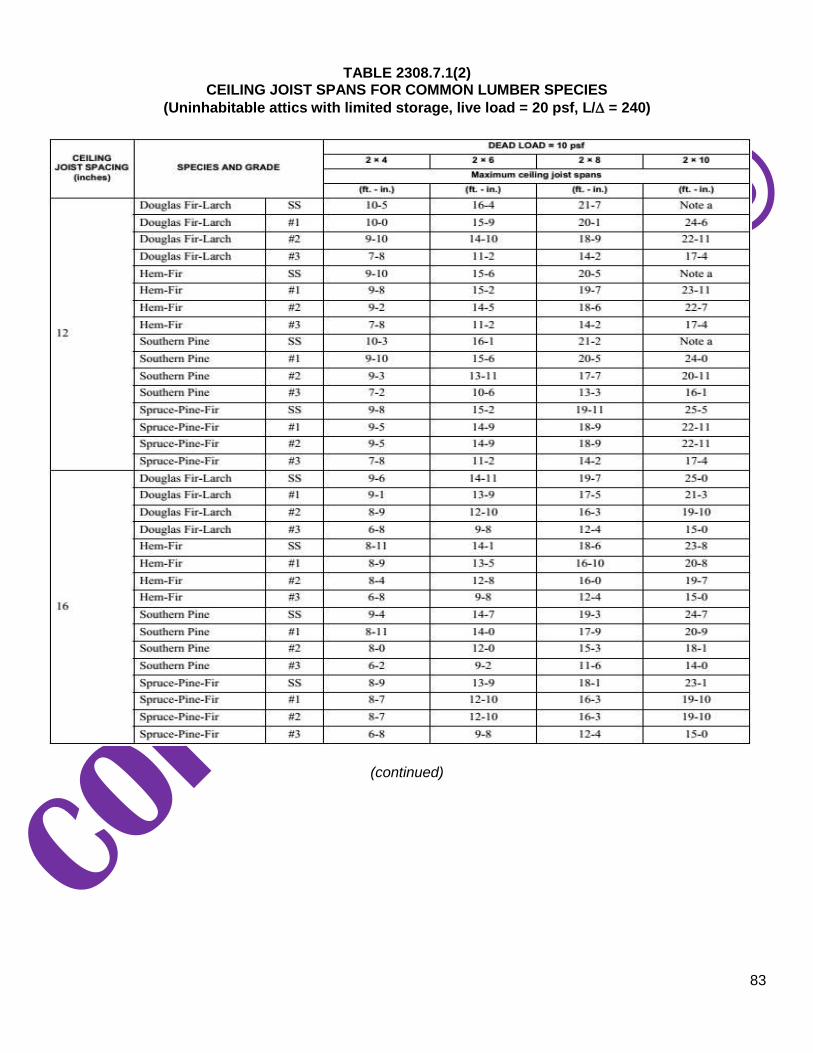
83
TABLE 2308.7.1(2) CEILING JOIST SPANS FOR COMMON LUMBER SPECIES
(Uninhabitable attics with limited storage, live load = 20 psf, L/ = 240)
(continued)

84
TABLE 2308.7.1(2)—continued CEILING JOIST SPANS FOR COMMON LUMBER SPECIES
(Uninhabitable attics with limited storage, live load = 20 psf, L/ = 240)
Check sources for availability of lumber in lengths greater than 20 feet. For SI: 1 inch = 25.4 mm, 1 foot = 304.8 mm, 1 pound per square foot = 0.0479 kPa. a. Span exceeds 26 feet in length.

85
2308.7.2 Rafter spans. Spans for rafters shall be in accordance with Table 2308.7.2(1), 2308.7.2(2), 2308.7.2(3), 2308.7.2(4), 2308.7.2(5) or 2308.7.2(6). For other grades and species and other loading conditions, refer to the AWC STJR. The span of each rafter shall be measured along the horizontal projection of the rafter.
TABLE 2308.7.2(1) RAFTER SPANS FOR COMMON LUMBER SPECIES
(Roof live load = 20 psf, ceiling not attached to rafters, L/ = 180)
(continued)

86
TABLE 2308.7.2(1)—continued RAFTER SPANS FOR COMMON LUMBER SPECIES
(Roof live load = 20 psf, ceiling not attached to rafters, L/ = 180)
Check sources for availability of lumber in lengths greater than 20 feet. For SI: 1 inch = 25.4 mm, 1 foot = 304.8 mm, 1 pound per square foot = 0.0479 kPa. a. The tabulated rafter spans assume that ceiling joists are located at the bottom of the attic space or that some other method of
resisting the outward push of the rafters on the bearing walls, such as rafter ties, is provided at that location. Where ceiling joists or rafter ties are located higher in the attic space, the rafter spans shall be multiplied by the adjustment factors in Table 2308.7.2(7).
b. Span exceeds 26 feet in length.

87
TABLE 2308.7.2(2) RAFTER SPANS FOR COMMON LUMBER SPECIES
(Roof live load = 20 psf, ceiling attached to rafters, L/= 240)
(continued)
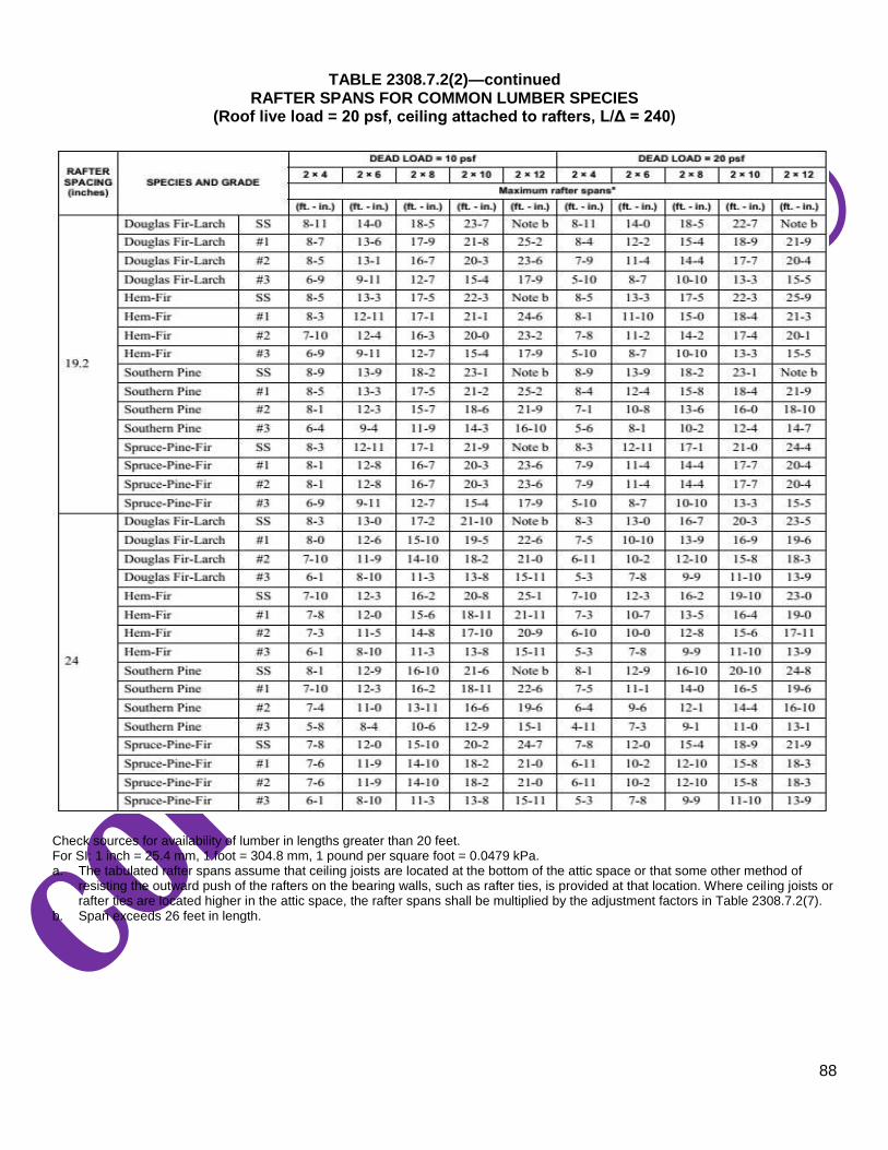
88
TABLE 2308.7.2(2)—continued RAFTER SPANS FOR COMMON LUMBER SPECIES
(Roof live load = 20 psf, ceiling attached to rafters, L/Δ = 240)
Check sources for availability of lumber in lengths greater than 20 feet. For SI: 1 inch = 25.4 mm, 1 foot = 304.8 mm, 1 pound per square foot = 0.0479 kPa. a. The tabulated rafter spans assume that ceiling joists are located at the bottom of the attic space or that some other method of
resisting the outward push of the rafters on the bearing walls, such as rafter ties, is provided at that location. Where ceiling joists or rafter ties are located higher in the attic space, the rafter spans shall be multiplied by the adjustment factors in Table 2308.7.2(7).
b. Span exceeds 26 feet in length.

89
TABLE 2308.7.2(3) RAFTER SPANS FOR COMMON LUMBER SPECIES
(Ground snow load = 30 psf, ceiling not attached to rafters, L/ = 180)
(continued)
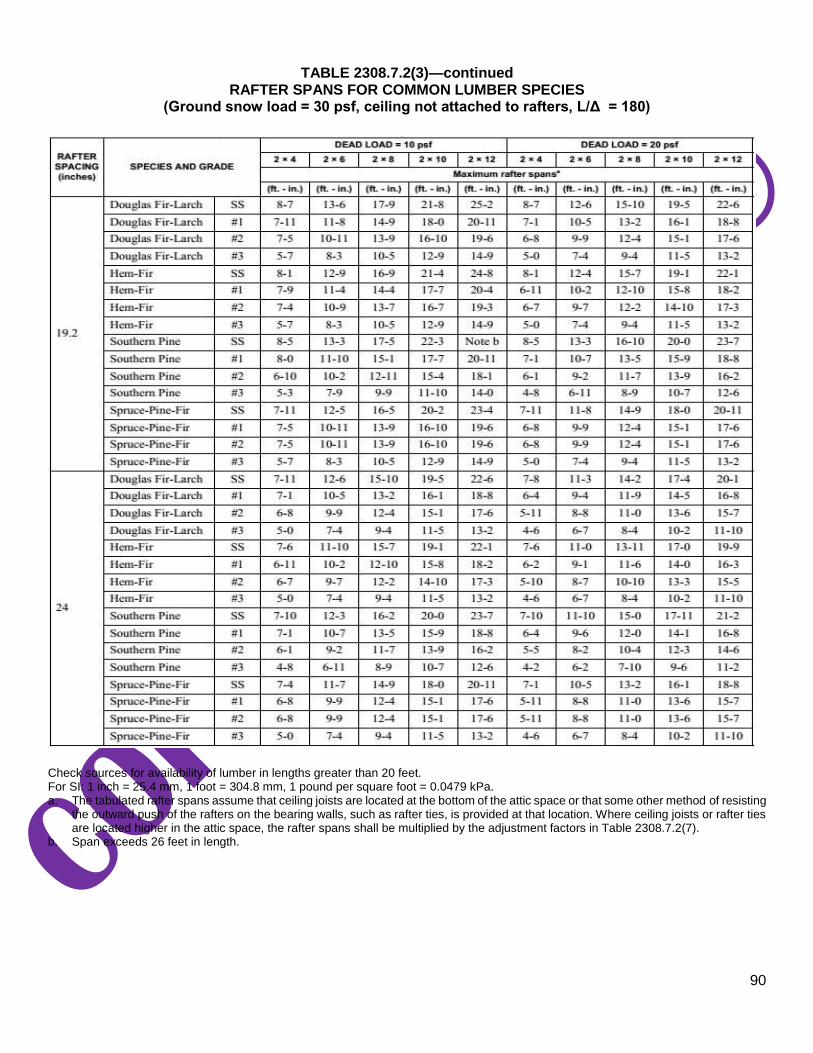
90
TABLE 2308.7.2(3)—continued RAFTER SPANS FOR COMMON LUMBER SPECIES
(Ground snow load = 30 psf, ceiling not attached to rafters, L/Δ = 180)
Check sources for availability of lumber in lengths greater than 20 feet. For SI: 1 inch = 25.4 mm, 1 foot = 304.8 mm, 1 pound per square foot = 0.0479 kPa. a. The tabulated rafter spans assume that ceiling joists are located at the bottom of the attic space or that some other method of resisting
the outward push of the rafters on the bearing walls, such as rafter ties, is provided at that location. Where ceiling joists or rafter ties are located higher in the attic space, the rafter spans shall be multiplied by the adjustment factors in Table 2308.7.2(7).
b. Span exceeds 26 feet in length.
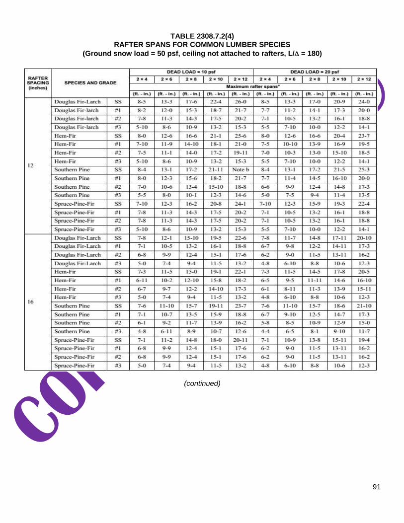
91
TABLE 2308.7.2(4) RAFTER SPANS FOR COMMON LUMBER SPECIES
(Ground snow load = 50 psf, ceiling not attached to rafters, L/ = 180)
(continued)
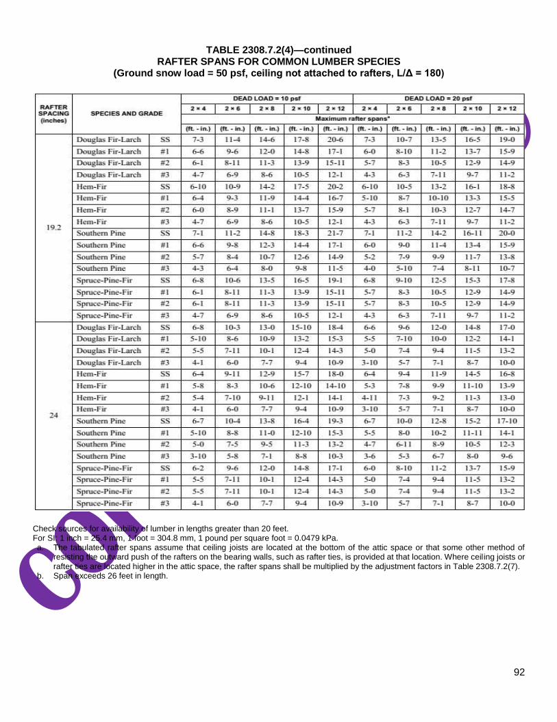
92
TABLE 2308.7.2(4)—continued RAFTER SPANS FOR COMMON LUMBER SPECIES
(Ground snow load = 50 psf, ceiling not attached to rafters, L/Δ = 180)
Check sources for availability of lumber in lengths greater than 20 feet. For SI: 1 inch = 25.4 mm, 1 foot = 304.8 mm, 1 pound per square foot = 0.0479 kPa. a. The tabulated rafter spans assume that ceiling joists are located at the bottom of the attic space or that some other method of
resisting the outward push of the rafters on the bearing walls, such as rafter ties, is provided at that location. Where ceiling joists or rafter ties are located higher in the attic space, the rafter spans shall be multiplied by the adjustment factors in Table 2308.7.2(7).
b. Span exceeds 26 feet in length.

93
TABLE 2308.7.2(5) RAFTER SPANS FOR COMMON LUMBER SPECIES
(Ground snow load = 30 psf, ceiling attached to rafters, L/ = 240)
(continued)

94
TABLE 2308.7.2(5)—continued RAFTER SPANS FOR COMMON LUMBER SPECIES
(Ground snow load = 30 psf, ceiling attached to rafters, L/Δ = 240)
Check sources for availability of lumber in lengths greater than 20 feet. For SI: 1 inch = 25.4 mm, 1 foot = 304.8 mm, 1 pound per square foot = 0.0479 kPa.
a. The tabulated rafter spans assume that ceiling joists are located at the bottom of the attic space or that some other method of resisting the outward push of the rafters on the bearing walls, such as rafter ties, is provided at that location. Where ceiling joists or rafter ties are located higher in the attic space, the rafter spans shall be multiplied by the adjustment factors in Table 2308.7.2(7). b. Span exceeds 26 feet in length.

95
TABLE 2308.7.2(6) RAFTER SPANS FOR COMMON LUMBER SPECIES
(Ground snow load = 50 psf, ceiling attached to rafters, L/ = 240)
(continued)
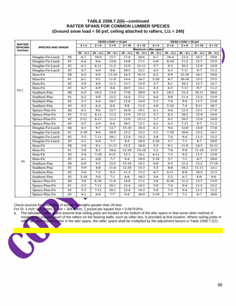
96
TABLE 2308.7.2(6)—continued RAFTER SPANS FOR COMMON LUMBER SPECIES
(Ground snow load = 50 psf, ceiling attached to rafters, L/ = 240)
Check sources for availability of lumber in lengths greater than 20 feet. For SI: 1 inch = 25.4 mm, 1 foot = 304.8 mm, 1 pound per square foot = 0.0479 kPa. a. The tabulated rafter spans assume that ceiling joists are located at the bottom of the attic space or that some other method of
resisting the outward push of the rafters on the bearing walls, such as rafter ties, is provided at that location. Where ceiling joists or rafter ties are located higher in the attic space, the rafter spans shall be multiplied by the adjustment factors in Table 2308.7.2(7).
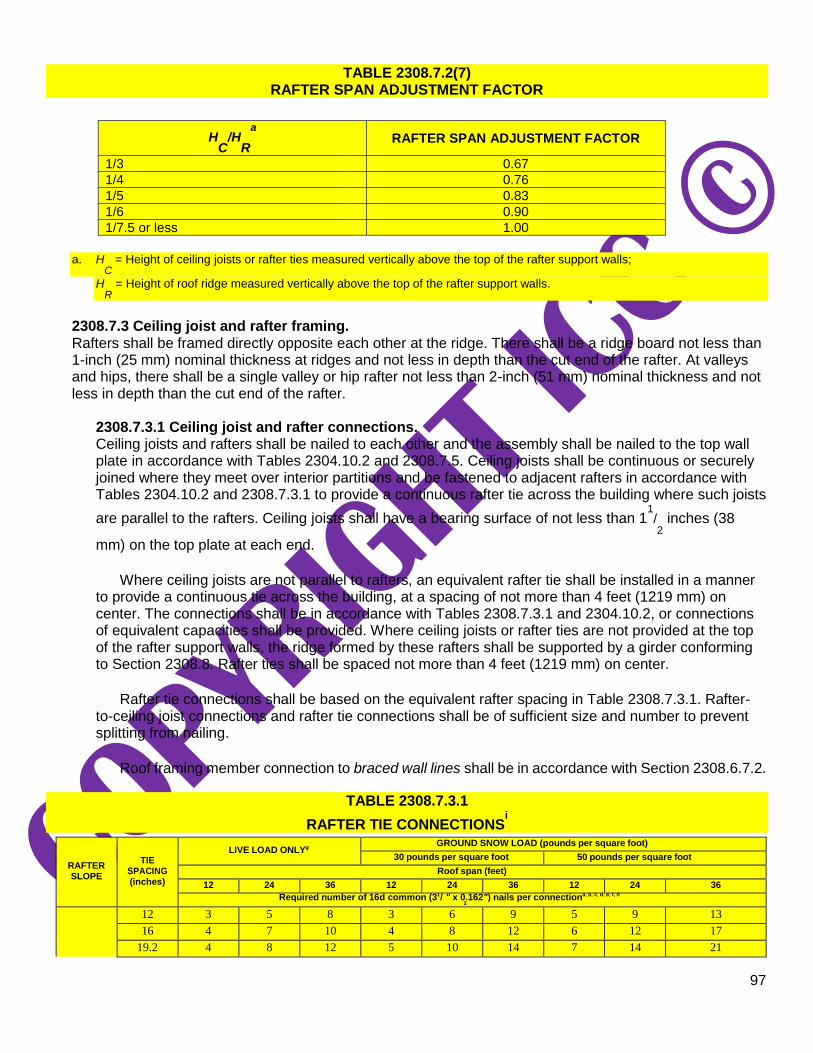
97
TABLE 2308.7.2(7) RAFTER SPAN ADJUSTMENT FACTOR
HC
/HR
a RAFTER SPAN ADJUSTMENT FACTOR
1/3 0.67
1/4 0.76
1/5 0.83
1/6 0.90
1/7.5 or less 1.00
a. H
C = Height of ceiling joists or rafter ties measured vertically above the top of the rafter support walls;
HR
= Height of roof ridge measured vertically above the top of the rafter support walls.
2308.7.3 Ceiling joist and rafter framing. Rafters shall be framed directly opposite each other at the ridge. There shall be a ridge board not less than 1-inch (25 mm) nominal thickness at ridges and not less in depth than the cut end of the rafter. At valleys and hips, there shall be a single valley or hip rafter not less than 2-inch (51 mm) nominal thickness and not less in depth than the cut end of the rafter.
2308.7.3.1 Ceiling joist and rafter connections. Ceiling joists and rafters shall be nailed to each other and the assembly shall be nailed to the top wall plate in accordance with Tables 2304.10.2 and 2308.7.5. Ceiling joists shall be continuous or securely joined where they meet over interior partitions and be fastened to adjacent rafters in accordance with Tables 2304.10.2 and 2308.7.3.1 to provide a continuous rafter tie across the building where such joists
are parallel to the rafters. Ceiling joists shall have a bearing surface of not less than 11/2 inches (38
mm) on the top plate at each end.
Where ceiling joists are not parallel to rafters, an equivalent rafter tie shall be installed in a manner
to provide a continuous tie across the building, at a spacing of not more than 4 feet (1219 mm) on center. The connections shall be in accordance with Tables 2308.7.3.1 and 2304.10.2, or connections of equivalent capacities shall be provided. Where ceiling joists or rafter ties are not provided at the top of the rafter support walls, the ridge formed by these rafters shall be supported by a girder conforming to Section 2308.8. Rafter ties shall be spaced not more than 4 feet (1219 mm) on center.
Rafter tie connections shall be based on the equivalent rafter spacing in Table 2308.7.3.1. Rafter-
to-ceiling joist connections and rafter tie connections shall be of sufficient size and number to prevent splitting from nailing.
Roof framing member connection to braced wall lines shall be in accordance with Section 2308.6.7.2.
TABLE 2308.7.3.1
RAFTER TIE CONNECTIONSi
RAFTER SLOPE
TIE SPACING (inches)
LIVE LOAD ONLYg
GROUND SNOW LOAD (pounds per square foot)
30 pounds per square foot 50 pounds per square foot
Roof span (feet)
12 24 36 12 24 36 12 24 36
Required number of 16d common (31/ " x 0.162") nails per connectiona, b, c, d, e, f, h
2
12 3 5 8 3 6 9 5 9 13
16 4 7 10 4 8 12 6 12 17
19.2 4 8 12 5 10 14 7 14 21

98
3:12 24 5 10 15 6 12 18 9 17 26
32 7 13 20 8 16 24 12 23 34
48 10 20 29 12 24 35 17 34 51
4:12
12 3 4 6 3 5 7 4 7 10
16 3 5 8 3 6 9 5 9 13
19.2 3 6 9 4 7 11 6 11 16
24 4 8 11 5 9 13 7 13 19
32 5 10 15 6 12 18 9 17 26
48 8 15 22 9 18 26 13 26 38
5:12
12 3 3 5 3 4 6 3 6 8
16 3 4 6 3 5 7 4 7 11
19.2 3 5 7 3 6 9 5 9 13
24 3 6 9 4 7 11 6 11 16
32 4 8 12 5 10 14 7 14 21
48 6 12 18 7 14 21 11 21 31
7:12
12 3 3 4 3 3 4 3 4 6
16 3 3 5 3 4 5 3 5 8
19.2 3 4 5 3 4 6 3 6 9
24 3 5 7 3 5 8 4 8 11
32 3 6 9 4 7 10 5 10 15
48 5 9 13 5 10 15 8 15 22
9:12
12 3 3 3 3 3 3 3 3 5
16 3 3 4 3 3 4 3 4 6
19.2 3 3 4 3 4 5 3 5 7
24 3 4 5 3 4 6 3 6 9
32 3 5 7 3 6 8 4 8 12
48 4 7 10 4 8 12 6 12 17
12:12
12 3 3 3 3 3 3 3 3 4
16 3 3 3 3 3 3 3 3 5
19.2 3 3 3 3 3 4 3 4 6
24 3 3 4 3 3 5 3 5 7
32 3 4 5 3 4 6 3 6 9
48 3 5 8 3 6 9 5 9 13
For SI: 1 inch = 25.4 mm, 1 foot = 304.8 mm, 1 pound per square foot = 47.8 N/m2.
a. 10d common (3″ × 0.148″) nails shall be permitted to be substituted for 16d common (31/2″ × 0.162″) nails where the required number
of nails is taken as 1.2 times the required number of 16d common nails, rounded up to the next full nail. b. Rafter tie heel joint connections are not required where the ridge is supported by a load-bearing wall, header or ridge beam. c. Where intermediate support of the rafter is provided by vertical struts or purlins to a load-bearing wall, the tabulated heel joint
connection requirements are permitted to be reduced proportionally to the reduction in span. d. Equivalent nailing patterns are required for ceiling joist to ceiling joist lap splices. e. Connected members shall be of sufficient size to prevent splitting due to nailing. f. For snow loads less than 30 pounds per square foot, the required number of nails is permitted to be reduced by multiplying by the
ratio of actual snow load plus 10 divided by 40, but not less than the number required for no snow load. g. Applies to roof live load of 20 psf or less. h. Tabulated heel joint connection requirements assume that ceiling joists or rafter ties are located at the bottom of the attic space.
Where ceiling joists or rafter ties are located higher in the attic, heel joint connection requirements shall be increased by the adjustment factors in Table 2308.7.3.1(1).
i. Tabulated requirements are based on 10 psf roof dead load in combination with the specified roof snow load and roof live load.
TABLE 2308.7.3.1(1) HEEL JOINT CONNECTION ADJUSTMENT FACTORS
HC
/HR
a, b HEEL JOINT CONNECTION ADJUSTMENT FACTOR
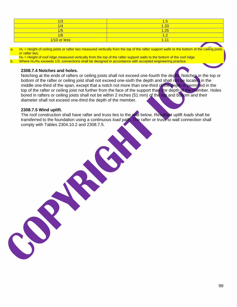
99
1/3 1.5
1/4 1.33
1/5 1.25
1/6 1.2
1/10 or less 1.11
a. HC = Height of ceiling joists or rafter ties measured vertically from the top of the rafter support walls to the bottom of the ceiling joists
or rafter ties; HR = Height of roof ridge measured vertically from the top of the rafter support walls to the bottom of the roof ridge.
b. Where HC/HR exceeds 1/3, connections shall be designed in accordance with accepted engineering practice.
2308.7.4 Notches and holes. Notching at the ends of rafters or ceiling joists shall not exceed one-fourth the depth. Notches in the top or bottom of the rafter or ceiling joist shall not exceed one-sixth the depth and shall not be located in the middle one-third of the span, except that a notch not more than one-third of the depth is permitted in the top of the rafter or ceiling joist not further from the face of the support than the depth of the member. Holes bored in rafters or ceiling joists shall not be within 2 inches (51 mm) of the top and bottom and their diameter shall not exceed one-third the depth of the member.
2308.7.5 Wind uplift. The roof construction shall have rafter and truss ties to the wall below. Resultant uplift loads shall be transferred to the foundation using a continuous load path. The rafter or truss to wall connection shall comply with Tables 2304.10.2 and 2308.7.5.

100
TABLE 2308.7.5
REQUIRED RATING OF APPROVED UPLIFT CONNECTORS (pounds)a, b, c, e, f, g, h
NOMINAL DESIGN WIND
SPEED, Vasd
i
ROOF SPAN (feet) OVERHANGS
(pounds/feet)d 12 20 24 28 32 36 40
85 -72 -120 -145 -169 -193 -217 -241 -38.55
90 -91 -151 -181 -212 -242 -272 -302 -43.22
100 -131 -281 -262 -305 -349 -393 -436 -53.36
110 -175 -292 -351 -409 -467 -526 -584 -64.56
For SI: 1 inch = 25.4 mm, 1 foot = 304.8 mm, 1 mile per hour = 1.61 km/hr, 1 pound = 0.454 Kg, 1 pound/foot = 14.5939 N/m. a. The uplift connection requirements are based on a 30-foot mean roof height located in Exposure B. For Exposure C or D and for
other mean roof heights, multiply the loads by the following adjustment coefficients:
Mean Roof Height (feet)
EXPOSURE 15 20 25 30 35 40 45 50 55 60
B 1.00 1.00 1.00 1.00 1.05 1.09 1.12 1.16 1.19 1.22
C 1.21 1.29 1.35 1.40 1.45 1.49 1.53 1.56 1.59 1.62
D 1.47 1.55 1.61 1.66 1.70 1.74 1.78 1.81 1.84 1.87
b. The uplift connection requirements are based on the framing being spaced 24 inches on center. Multiply by 0.67 for framing spaced
16 inches on center and multiply by 0.5 for framing spaced 12 inches on center. c. The uplift connection requirements include an allowance for 10 pounds of dead load. d. The uplift connection requirements do not account for the effects of overhangs. The magnitude of the loads shall be increased by
adding the overhang loads found in the table. The overhang loads are based on framing spaced 24 inches on center. The overhang loads given shall be multiplied by the overhang projection and added to the roof uplift value in the table.
e. The uplift connection requirements are based on wind loading on end zones as defined in Figure 28.5-1 of ASCE 7. Connection loads for connections located a distance of 20 percent of the least horizontal dimension of the building from the corner of the building are permitted to be reduced by multiplying the table connection value by 0.7 and multiplying the overhang load by 0.8.
f. For wall-to-wall and wall-to-foundation connections, the capacity of the uplift connector is permitted to be reduced by 100 pounds for each full wall above. (For example, if a 500-pound rated connector is used on the roof framing, a 400-pound rated connector is permitted at the next floor level down).
g. Interpolation is permitted for intermediate values of Vasd
and roof spans.
h. The rated capacity of approved tie-down devices is permitted to include up to a 60-percent increase for wind effects where allowed by material specifications.
i. Vasd
shall be determined in accordance with Section 1609.3.1.
2308.7.6 Framing around openings. Trimmer and header rafters shall be doubled, or of lumber of equivalent cross section, where the span of the header exceeds 4 feet (1219 mm). The ends of header rafters that are more than 6 feet (1829 mm) in length shall be supported by framing anchors or rafter hangers unless bearing on a beam, partition or wall.
101
2308.7.6.1 Openings in roof diaphragms in Seismic Design Categories B, C, D and E. In buildings classified as Seismic Design Category B, C, D or E. openings in horizontal diaphragms with a dimension that is greater than 4 feet (1219 mm) shall be constructed with metal ties and blocking in accordance with this section and Figure 2308.4.4.1(1). Metal ties shall be not less than 0.058 inch [1.47
mm (16 galvanized gage)] in thickness by 11/2 inches (38 mm) in width and shall have a yield stress not
less than 33,000 psi (227 Mpa). Blocking shall extend not less than the dimension of the opening in the direction of the tie and blocking. Ties shall be attached to blocking in accordance with the manufacturer’s instructions but with not less than eight 16d common nails on each side of the header-joist intersection.
2308.7.7 Purlins. Purlins to support roof loads are permitted to be installed to reduce the span of rafters within allowable limits and shall be supported by struts to bearing walls. The maximum span of 2-inch by 4-inch (51 mm by 102 mm) purlins shall be 4 feet (1219 mm). The maximum span of the 2-inch by 6-inch (51 mm by 152 mm) purlin shall be 6 feet (1829 mm), but the purlin shall not be smaller than the supported rafter. Struts shall be not less than 2-inch by 4-inch (51 mm by 102 mm) members. The unbraced length of struts shall not exceed 8 feet (2438 mm) and the slope of the struts shall be not less than 45 degrees (0.79 rad) from the horizontal.
2308.7.8 Blocking. Roof rafters and ceiling joists shall be supported laterally to prevent rotation and lateral displacement in accordance with Section 2308.4.6 and connected to braced wall lines in accordance with Section 2308.6.7.2.
2308.7.9 Engineered wood products. Prefabricated wood I-joists, structural glued-laminated timber and structural composite lumber shall not be notched or drilled except where permitted by the manufacturer’s recommendations or where the effects of such alterations are specifically considered in the design of the member by a registered design professional.
2308.7.10 Roof sheathing. Roof sheathing shall be in accordance with Tables 2304.8(3) and 2304.8(5) for wood structural panels, and Tables 2304.8(1) and 2304.8(2) for lumber and shall comply with Section 2304.8.2.
2308.7.11 Joints. Joints in lumber sheathing shall occur over supports unless approved end-matched lumber is used, in which case each piece shall bear on not fewer than two supports.
2308.7.12 Roof planking. Planking shall be designed in accordance with the general provisions of this code.
In lieu of such design, 2-inch (51 mm) tongue-and groove planking is permitted in accordance with
Table 2308.7.12. Joints in such planking are permitted to be randomly spaced, provided that the system is applied to not less than three continuous spans, planks are center matched and end matched or splined, each plank bears on one support or more, and joints are separated by not less than 24 inches (610 mm) in adjacent pieces.

102
TABLE 2308.7.12 ALLOWABLE SPANS FOR 2-INCH TONGUE-AND-GROOVE DECKING
SPANa
(feet)
LIVE LOAD (pounds per square
foot) DEFLECTION LIMIT
BENDING STRESS (f) (pounds per square
inch)
MODULUS OF ELASTICITY (E) (pounds
per square inch)
Roofs
4
20 1/240 1/360
160 170,000 256,000
30 1/240 1/360
210 256,000 384,000
40 1/240 1/360
270 340,000 512,000
4.5
20 1/240 1/360
200 242,000 305,000
30 1/240 1/360
270 363,000 405,000
40 1/240 1/360
350 484,000 725,000
5.0
20 1/240 1/360
250 332,000 500,000
30 1/240 1/360
330 495,000 742,000
40 1/240 1/360
420 660,000
1,000,000
5.5
20 1/240 1/360
300 442,000 660,000
30 1/240 1/360
400 662,000 998,000
40 1/240 1/360
500 884,000
1,330,000
6.0
20 1/240 1/360
360 575,000 862,000
30 1/240 1/360
480 862,000
1,295,000
40 1/240 1/360
600 1,150,000 1,730,000
(continued)

103
TABLE 2308.7.12—continued ALLOWABLE SPANS FOR 2-INCH TONGUE-AND-GROOVE DECKING
SPANa
(feet)
LIVE LOAD (pounds per square
foot)
DEFLECTION LIMIT
BENDING STRESS (f) (pounds per square
inch)
MODULUS OF ELASTICITY (E) (pounds
per square inch)
Roofs
6.5
20 1/240 1/360
420 595,000 892,000
30 1/240 1/360
560 892,000
1,340,000
40 1/240 1/360
700 1,190,000 1,730,000
7.0
20 1/240 1/360
490 910,000
1,360,000
30 1/240 1/360
650 1,370,000 2,000,000
40 1/240 1/360
810 1,820,000 2,725,000
7.5
20 1/240 1/360
560 1,125,000 1,685,000
30 1/240 1/360
750 1,685,000 2,530,000
40 1/240 1/360
930 2,250,000 3,380,000
8.0
20 1/240 1/360
640 1,360,000 2,040,000
30 1/240 1/360
850 2,040,000 3,060,000
Floors
4 4.5 5.0
40 1/360 840 950
1,060
1,000,000 1,300,000 1,600,000
For SI: 1 inch = 25.4 mm, 1 foot = 304.8 mm, 1 pound per square foot = 0.0479 kN/m2, 1 pound per square inch = 0.00689 N/mm
2.
a. Spans are based on simple beam action with 10 pounds per square foot dead load and provisions for a 300-pound concentrated load on a 12-inch width of decking. Random layup is permitted in accordance with the provisions of Section 2308.7.12. Lumber
thickness is 11/2 inches nominal.
2308.7.13 Wood trusses. Wood trusses shall be designed in accordance with Section 2303.4. Connection to braced wall lines shall be in accordance with Section 2308.6.7.2.
2308.7.14 Attic ventilation. For attic ventilation, see Section 1202.2.1.
2308.8 Design of elements. Combining of engineered elements or systems and conventionally specified elements or systems shall be permitted subject to the limits of Sections 2308.8.1 and 2308.8.2.
2308.8.1 Elements exceeding limitations of conventional construction. Where a building of otherwise conventional construction contains structural elements exceeding the limits

104
of Section 2308.2, these elements and the supporting load path shall be designed in accordance with accepted engineering practice and the provisions of this code.
2308.8.2 Structural elements or systems not described herein. Where a building of otherwise conventional construction contains structural elements or systems not described in Section 2308, these elements or systems shall be designed in accordance with accepted engineering practice and the provisions of this code. The extent of such design need only demonstrate compliance of the nonconventional elements with other applicable provisions of this code and shall be compatible with the performance of the conventionally framed system.
SECTION 2309
WOOD FRAME CONSTRUCTION MANUAL 2309.1 Wood Frame Construction Manual. Structural design in accordance with the AWC WFCM shall be permitted for buildings assigned to Risk Category I or II subject to the limitations of Section 1.1.3 of the AWC WFCM and the load assumptions contained therein. Structural elements beyond these limitations shall be designed in accordance with accepted engineering practice.