chapter 23 moveable bridges - oregon.gov
TRANSCRIPT

2020 Traffic Signal Design Manual
Oregon Department of Transportation 23-i January 2020 Traffic Standards and Asset Management Unit Chapter 23 – Moveable Bridges
Chapter 23 MOVEABLE BRIDGES
Contents
23 Moveable Bridges ................................................................................................................. 23-1 23.1 General ........................................................................................................................................ 23-1 23.2 Design Responsibility .................................................................................................................. 23-1 23.3 Operational Approval .................................................................................................................. 23-2 23.4 Design Approval .......................................................................................................................... 23-2 23.5 Existing Moveable Bridges on the State Highway System .......................................................... 23-2
23.5.1 Non-Compliant Existing Traffic Control Devices (TCD) ................................................................... 23-3 23.6 Bridge Warning Gate and STOP Line Placement ......................................................................... 23-7 23.7 Signal Head Type and Placement ................................................................................................ 23-8 23.8 Mounting Signal Heads and Signs ............................................................................................... 23-9 23.9 Traffic Control Device Sequence ............................................................................................... 23-10
23.9.1 No Sight Distance Restrictions to Signal Heads ............................................................................ 23-11 23.9.2 Sight Distance Restrictions to Signal Heads .................................................................................. 23-12 23.9.3 Sight Distance Restrictions to Signal Heads (Special Application Only) ........................................ 23-13 23.9.4 Unique Traffic Control Devices: Columbia River (Interstate) NB .................................................. 23-14 23.9.5 Unique Traffic Control Devices: Columbia River (Interstate) SB ................................................... 23-17

2020 Traffic Signal Design Manual
Oregon Department of Transportation 23-1 January 2020 Traffic Standards and Asset Management Unit Chapter 23 – Moveable Bridges
23 MOVEABLE BRIDGES
23.1 General
Traffic control for moveable bridges is covered in section 4J of the Manual on Uniform Traffic Control Devices. Additional information specific to Oregon is presented in this chapter.
23.2 Design Responsibility
The Bridge Section has historically been responsible for the design, maintenance and operation of all traffic control devices that are activated by the moveable bridge control system (which includes the signal indications and flashing beacon warning devices). As such, the Signal Designer has had little involvement in the past with the traffic control devices used for moveable bridges. However, due to several recent moveable bridge projects, it became clear that more information about the traffic control devices used and more coordination between the Traffic Section and the Bridge Section was needed. The Bridge, Signal, and Sign Designer should work closely together to ensure that the design for each discipline is detailed or referenced appropriately. The Bridge Plans Sheets should detail the following items:
Control system that activates the traffic signals and flashing beacons (cabinets, power source, termination of wires, etc.)
Location of Gate arms
Audible devices for warning traffic
Non-standard poles, foundations, or mounting for signal heads, signs, and flashing beacons
Electrical conduit routed on/through the bridge structure (including expansion fittings)
Junction Boxes located on the bridge structure
The Signal Plan Sheets should detail the following items:
Location of the traffic signals
Location of the STOP line
Use of and location of the flashing beacon warning devices
PTR signs (site specific for the I-5 NB and SB Columbia River Bridge only)
Wiring from the traffic signals and flashing beacons to the control system (wire terminations are detailed on the bridge plans)
Electrical conduit not routed on/through the bridge structure
Connection details for conduit going onto (or off) of the bridge structure (Junction box, expansion fitting, etc.)
Standard poles, foundations, and mounting for signal heads, signs & flashing beacons The Signing Plan Sheets should detail the following items:
Ground mounted signs that do not have a flashing beacon

2020 Traffic Signal Design Manual
Oregon Department of Transportation 23-2 January 2020 Traffic Standards and Asset Management Unit Chapter 23 – Moveable Bridges
23.3 Operational Approval
The decision to install a moveable bridge resides with the Bridge Section. Moveable bridges are typically not the most economical type of bridge to build or maintain, making it unlikely that a new moveable bridge will be built today. If a new moveable bridge is installed, the MUTCD Section 4J.01 requires both signals and gates (allowing a few exceptions under certain conditions). Therefore, State Traffic-Roadway Operational Approval is NOT required. Bridge Section is also responsible for the how the activated devices are operated during a bridge opening. The Yellow Change Interval duration shall follow the requirements stated in the Traffic Signal Policy and Guidelines.
23.4 Design Approval
Design Approval of the signal plan sheets is required. The Drawing Title for the plan sheets should be “Signal Plan”.
23.5 Existing Moveable Bridges on the State Highway System
There are 11 existing moveable bridges on the state highway system that will require repair or replacement in future years. It is likely that complete bridge replacement projects will decrease the number of existing moveable bridges as time goes on. Table 1 below shows the location of the 11 existing bridges and the type of lift. Table 1 | List of Moveable Bridges in Oregon
Bridge Name Region Route ODOT
Highway No. Milepoint Type of Bridge
1 Columbia River (Interstate) NB
1 I-5 1 308.38 Vertical Lift
2 Columbia River (Interstate) SB
1 I-5 1 308.38 Vertical Lift
3 New Youngs Bay 2 US 101 9 4.91 Vertical Lift
4 Old Youngs Bay 2 US
101B 105 6.89
Bascule: Double Leaf
5 Lewis and Clark River
2 US
101B 105 4.78
Bascule: Single Leaf
6 Siuslaw River 2 US 101 9 190.98 Bascule: Double Leaf
7 Umpqua River & McIntosh Slough
3 US 101 9 211.11 Swing
8 Coos River (Chandler)
3 OR 241 241 3.73 Vertical Lift
9 Isthmus Slough (Eastside)
3 OR 241 241 0.42 Bascule: Double Leaf
10 South Slough (Charleston)
3 OR 540 240 8.33 Bascule: Double Leaf
11 Coquille River (Bullards)
3 US 101 9 259.65 Vertical Lift

2020 Traffic Signal Design Manual
Oregon Department of Transportation 23-3 January 2020 Traffic Standards and Asset Management Unit Chapter 23 – Moveable Bridges
23.5.1 Non-Compliant Existing Traffic Control Devices (TCD)
There are several moveable bridges with traffic control devices that were commonly used in the past, but are no longer compliant with the current standards as described in this chapter. These devices, listed below, should be removed or replaced with compliant devices when possible:
Signal heads mounted horizontally. See Figure 23-1.
Use of a single Type 2 signal head to stop traffic. See Figure 23-1.
Use of only bridge warning gates with no traffic signals (i.e. Coos River – Chandler Moveable Bridge). Note: all 11 existing moveable bridges require both signals and gates as per the MUTCD. See Figure 23-2.
Mounting a STOP sign to the bridge warning gate. See Figure 23-3.
Use of an advance single signal head to warn traffic (custom Type: Flashing Yellow, Green, Flashing Yellow indications or Type 2). See Figure 23-4 and Figure 23-5.
Use of signs no longer in the MUTCD or the Oregon Sign Policy and Guidelines (DRAW BRIDGE AHEAD sign, DRAWBRIDGE ½ MILE sign). See Figure 23-6 and Figure 23-7.
Figure 23-1 | Non-Compliant Existing TCD: Single Signal Head to Stop Traffic Mounted Horizontally

2020 Traffic Signal Design Manual
Oregon Department of Transportation 23-4 January 2020 Traffic Standards and Asset Management Unit Chapter 23 – Moveable Bridges
Figure 23-2 | Non-Compliant Existing TCD: Use of Only Bridge Warning Gates with No Traffic Signals
Figure 23-3 | Non-Compliant Existing TCD: Mounting a STOP sign to the warning gate

2020 Traffic Signal Design Manual
Oregon Department of Transportation 23-5 January 2020 Traffic Standards and Asset Management Unit Chapter 23 – Moveable Bridges
Figure 23-4 | Non-Compliant Existing TCD: Single Advance Signal Head, Example 1
Figure 23-5 | Non-Compliant Existing TCD: Single Advance Signal Head, Example 2

2020 Traffic Signal Design Manual
Oregon Department of Transportation 23-6 January 2020 Traffic Standards and Asset Management Unit Chapter 23 – Moveable Bridges
Figure 23-6 | Non-Compliant Existing TCD: Outdated Signs, Example 1
Figure 23-7 | Non-Compliant Existing TCD: Outdated Signs, Example 2
2020 Traffic Signal Design Manual
Oregon Department of Transportation 23-7 January 2020 Traffic Standards and Asset Management Unit Chapter 23 – Moveable Bridges
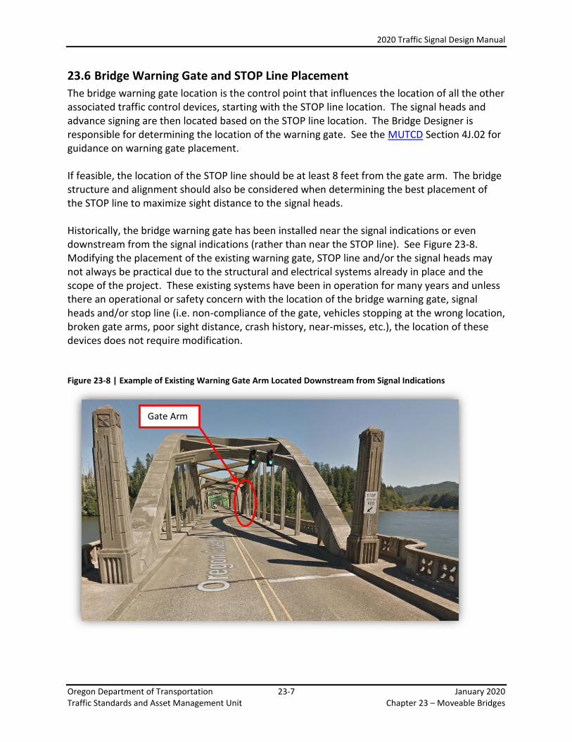
23.6 Bridge Warning Gate and STOP Line Placement
The bridge warning gate location is the control point that influences the location of all the other associated traffic control devices, starting with the STOP line location. The signal heads and advance signing are then located based on the STOP line location. The Bridge Designer is responsible for determining the location of the warning gate. See the MUTCD Section 4J.02 for guidance on warning gate placement. If feasible, the location of the STOP line should be at least 8 feet from the gate arm. The bridge structure and alignment should also be considered when determining the best placement of the STOP line to maximize sight distance to the signal heads. Historically, the bridge warning gate has been installed near the signal indications or even downstream from the signal indications (rather than near the STOP line). See Figure 23-8. Modifying the placement of the existing warning gate, STOP line and/or the signal heads may not always be practical due to the structural and electrical systems already in place and the scope of the project. These existing systems have been in operation for many years and unless there an operational or safety concern with the location of the bridge warning gate, signal heads and/or stop line (i.e. non-compliance of the gate, vehicles stopping at the wrong location, broken gate arms, poor sight distance, crash history, near-misses, etc.), the location of these devices does not require modification. Figure 23-8 | Example of Existing Warning Gate Arm Located Downstream from Signal Indications
Gate Arm

2020 Traffic Signal Design Manual
Oregon Department of Transportation 23-8 January 2020 Traffic Standards and Asset Management Unit Chapter 23 – Moveable Bridges
23.7 Signal Head Type and Placement
Basic requirements for signal head type and placement:
A minimum of two Type 2 Signal heads mounted vertically overhead shall be used to stop traffic
Heads shall be at least 8 feet apart, desirable 10 feet apart
Heads shall not be less than 45 feet from the STOP line, desirable 80 to 100 feet
Supplemental heads may be used if necessary to improve sight distance to the signal indications
A signal head per lane shall be used when there are 2 or more approach lanes
Figure 23-9 | Signal Head Type and Placement

2020 Traffic Signal Design Manual
Oregon Department of Transportation 23-9 January 2020 Traffic Standards and Asset Management Unit Chapter 23 – Moveable Bridges
23.8 Mounting Signal Heads and Signs
The bridge structure and alignment will determine how the signal heads and signs will be mounted. Signal heads shall be mounted vertically. Some locations will be able to accommodate standard traffic signal mast arm poles (with a custom foundation incorporated into the bridge structure) and standard sign and signal pedestal supports. See Figure 23-10. Other locations will require the signal heads and/or signs to be custom mounted on the bridge structure or on a custom support. See Figure 23-11. The Bridge Designer is responsible for any custom mounting or support details. Figure 23-10 | Standard Traffic Signal Mast Arm Pole Incorporated into the Bridge Deck
Figure 23-11 | Signal Heads and Sign Custom Mounted on Bridge Structure

2020 Traffic Signal Design Manual
Oregon Department of Transportation 23-10 January 2020 Traffic Standards and Asset Management Unit Chapter 23 – Moveable Bridges
23.9 Traffic Control Device Sequence
The following sections 23.9.1 through 23.9.3 show the standard sequence of signs and flashing beacons in advance of the moveable bridge based on the required sight distance to the signal heads. Section 23.9.4 is specific to the I-5 NB Columbia River Crossing and Section 23.9.5 is specific to the SB Columbia River Crossing. Sign location dimensions shown in sections 23.9.1 through 23.9.3 are based on AASHTO and MUTCD guidance; they may be adjusted as necessary according to site specific constraints, such as:
maximizing sight distance
Allowable locations on the bridge structure to mount traffic control devices and electrical features
Obtaining appropriate spacing between other required signs, especially those with flashing beacons (i.e. NARROW BRIDGE sign, bridge height/weight restriction signs, curve warning signs, bikes/peds on bridge when flashing sign).
Expected queue lengths during bridge openings
Location of nearby approaches/accesses
2020 Traffic Signal Design Manual
Oregon Department of Transportation 23-11 January 2020 Traffic Standards and Asset Management Unit Chapter 23 – Moveable Bridges
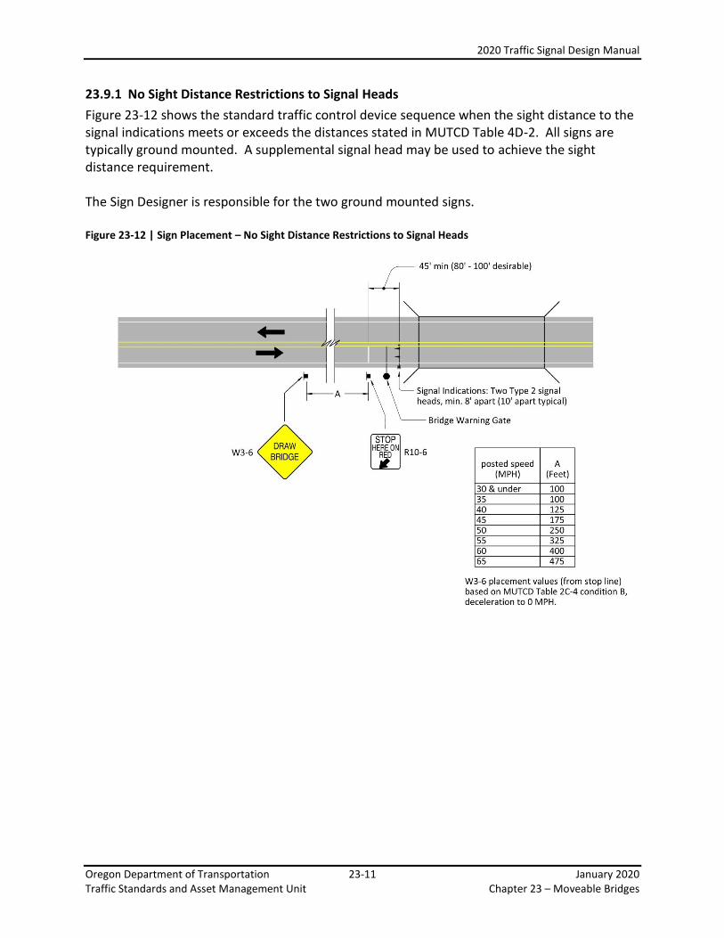
23.9.1 No Sight Distance Restrictions to Signal Heads
Figure 23-12 shows the standard traffic control device sequence when the sight distance to the signal indications meets or exceeds the distances stated in MUTCD Table 4D-2. All signs are typically ground mounted. A supplemental signal head may be used to achieve the sight distance requirement. The Sign Designer is responsible for the two ground mounted signs. Figure 23-12 | Sign Placement – No Sight Distance Restrictions to Signal Heads
2020 Traffic Signal Design Manual
Oregon Department of Transportation 23-12 January 2020 Traffic Standards and Asset Management Unit Chapter 23 – Moveable Bridges
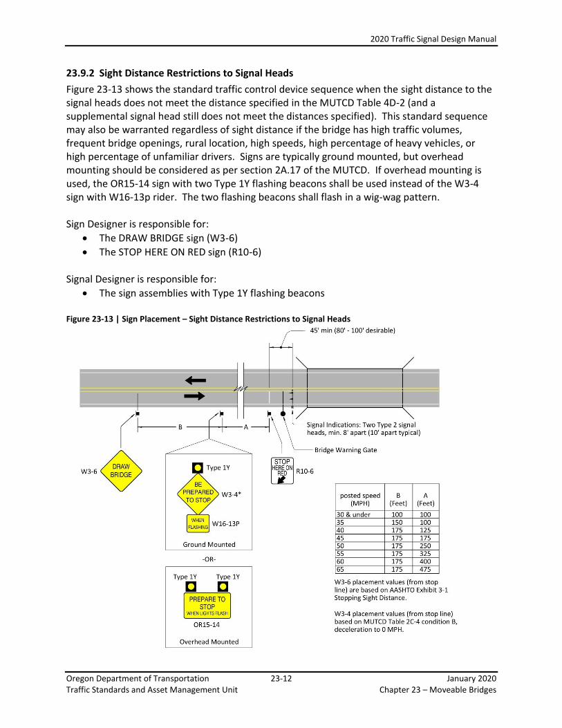
23.9.2 Sight Distance Restrictions to Signal Heads
Figure 23-13 shows the standard traffic control device sequence when the sight distance to the signal heads does not meet the distance specified in the MUTCD Table 4D-2 (and a supplemental signal head still does not meet the distances specified). This standard sequence may also be warranted regardless of sight distance if the bridge has high traffic volumes, frequent bridge openings, rural location, high speeds, high percentage of heavy vehicles, or high percentage of unfamiliar drivers. Signs are typically ground mounted, but overhead mounting should be considered as per section 2A.17 of the MUTCD. If overhead mounting is used, the OR15-14 sign with two Type 1Y flashing beacons shall be used instead of the W3-4 sign with W16-13p rider. The two flashing beacons shall flash in a wig-wag pattern. Sign Designer is responsible for:
The DRAW BRIDGE sign (W3-6)
The STOP HERE ON RED sign (R10-6) Signal Designer is responsible for:
The sign assemblies with Type 1Y flashing beacons
Figure 23-13 | Sign Placement – Sight Distance Restrictions to Signal Heads
2020 Traffic Signal Design Manual
Oregon Department of Transportation 23-13 January 2020 Traffic Standards and Asset Management Unit Chapter 23 – Moveable Bridges
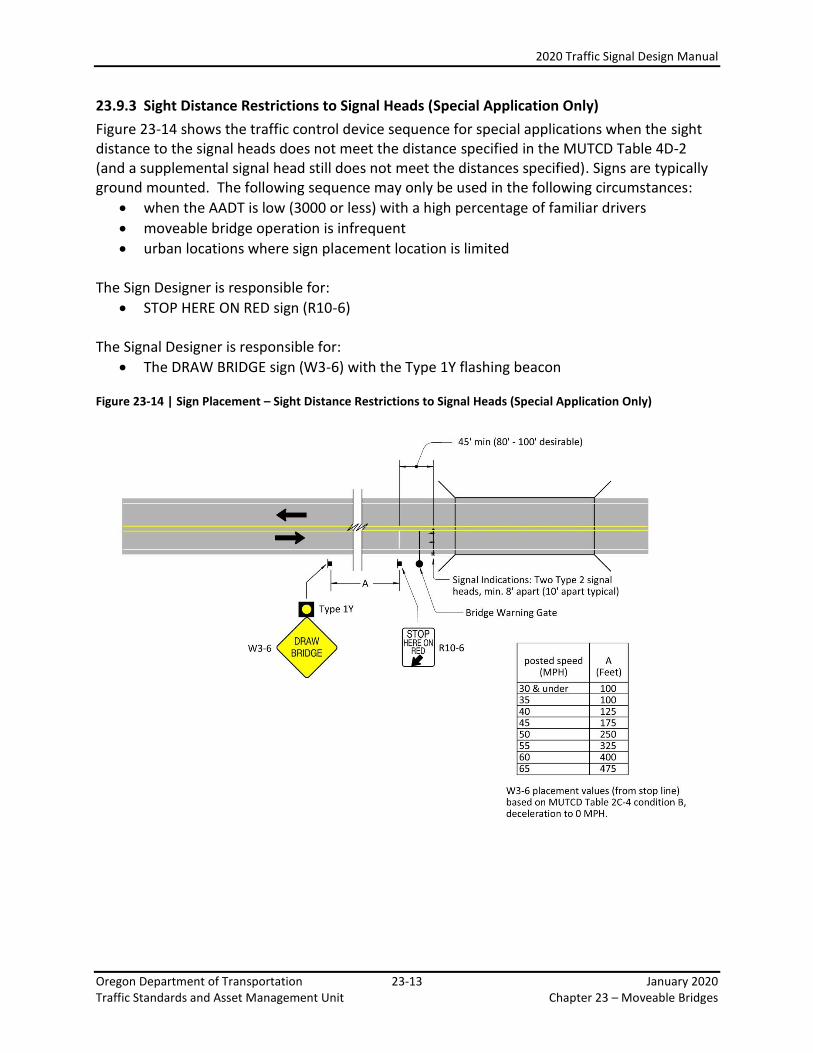
23.9.3 Sight Distance Restrictions to Signal Heads (Special Application Only)
Figure 23-14 shows the traffic control device sequence for special applications when the sight distance to the signal heads does not meet the distance specified in the MUTCD Table 4D-2 (and a supplemental signal head still does not meet the distances specified). Signs are typically ground mounted. The following sequence may only be used in the following circumstances:
when the AADT is low (3000 or less) with a high percentage of familiar drivers
moveable bridge operation is infrequent
urban locations where sign placement location is limited The Sign Designer is responsible for:
STOP HERE ON RED sign (R10-6) The Signal Designer is responsible for:
The DRAW BRIDGE sign (W3-6) with the Type 1Y flashing beacon Figure 23-14 | Sign Placement – Sight Distance Restrictions to Signal Heads (Special Application Only)

2020 Traffic Signal Design Manual
Oregon Department of Transportation 23-14 January 2020 Traffic Standards and Asset Management Unit Chapter 23 – Moveable Bridges
23.9.4 Unique Traffic Control Devices: Columbia River (Interstate) NB
Being a major interstate bridge, the traffic control devices used and the placement are unique from the other 10 existing bridges. All traffic control devices are custom mounted to the structure, except one device mounted on a sign bridge. This moveable bridge has been slated for replacement; however, it is uncertain when that project will move forward. If the existing traffic control devices need to be replaced, they should be replaced in-kind:
1st warning device: approx. 600 feet south of MLK overcrossing, Two Type 1Y flashing beacons mounted next to the custom “DRAWBRIDGE PREPARE TO STOP WHEN LIGHTS FLASH” sign. See Figure 23-15.
2nd warning device: Two Type 1Y flashing beacons mounted next to the custom “DRAWBRIDGE PREPARE TO STOP WHEN LIGHTS FLASH” sign. See Figure 23-16.
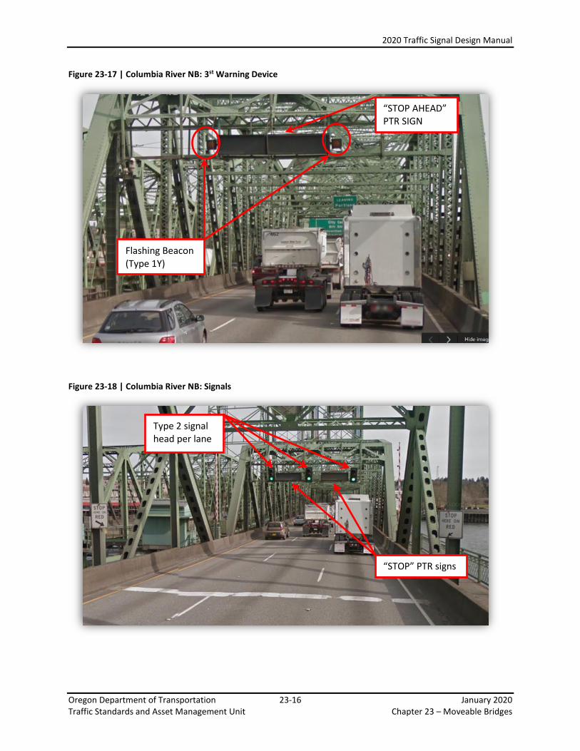
3rd warning device: Two Type 1Y flashing beacons mounted next to the “STOP AHEAD” PTR sign. See Figure 23-17.
Signals: Three Type 2 Signals Heads (one per each approach lane) and two “STOP” PTR signs. See Figure 23-18.
Figure 23-15 | Columbia River NB: 1st Warning Device

2020 Traffic Signal Design Manual
Oregon Department of Transportation 23-15 January 2020 Traffic Standards and Asset Management Unit Chapter 23 – Moveable Bridges
Figure 23-16 | Columbia River NB: 2st Warning Device
Flashing Beacon (Type 1Y)
2020 Traffic Signal Design Manual
Oregon Department of Transportation 23-16 January 2020 Traffic Standards and Asset Management Unit Chapter 23 – Moveable Bridges
Figure 23-17 | Columbia River NB: 3st Warning Device
Figure 23-18 | Columbia River NB: Signals
Flashing Beacon (Type 1Y)
“STOP AHEAD” PTR SIGN
Type 2 signal head per lane
“STOP” PTR signs
2020 Traffic Signal Design Manual
Oregon Department of Transportation 23-17 January 2020 Traffic Standards and Asset Management Unit Chapter 23 – Moveable Bridges
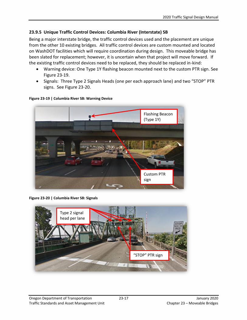
23.9.5 Unique Traffic Control Devices: Columbia River (Interstate) SB
Being a major interstate bridge, the traffic control devices used and the placement are unique from the other 10 existing bridges. All traffic control devices are custom mounted and located on WashDOT facilities which will require coordination during design. This moveable bridge has been slated for replacement; however, it is uncertain when that project will move forward. If the existing traffic control devices need to be replaced, they should be replaced in-kind:
Warning device: One Type 1Y flashing beacon mounted next to the custom PTR sign. See Figure 23-19.
Signals: Three Type 2 Signals Heads (one per each approach lane) and two “STOP” PTR signs. See Figure 23-20.
Figure 23-19 | Columbia River SB: Warning Device
Figure 23-20 | Columbia River SB: Signals
Flashing Beacon (Type 1Y)
Custom PTR sign
Type 2 signal head per lane
“STOP” PTR sign