chapter 2 stress and strain- axial loading · pdf filechapter 2 stress and strain- axial...
TRANSCRIPT

2-1 Introduction to Stress and Strain: Axial Loading
Chapter 2 Stress and Strain- Axial Loading
INTRODUCTION Stress and Strain
Repeated Loadings; Fatigue
Deformation of Members Under Axial Loading
Statically Indeterminate Problems
Temperature Effects
σ
ε
σ
CYCLES
A B C 58
1.2 0.8
100T CΔ = °
A B C 58
1.2 0.8
A B C
1.2 0.8

2-2 Introduction to Stress and Strain: Axial Loading
Saint-Venants Principle
Stress Concentrations
Shearing Strain
Poisson’s Ratio
Multiaxial Loading; Generalized Hooke’s Law
P
P
xσ
yσ
yσ
xσ
zσ
P P P P
P P P P
xσ
yσ
yσ
xσ
zσ

2-3 Normal Strain Under Axial Loading
NORMAL STRAIN UNDER AXIAL LOADING
A B
L
A
B
P
δ Lδ ε =

2-4 Stress-Strain Diagrams
STRESS-STRAIN DIAGRAMS
σ
ε
σ
ε
P P
Low-carbon steel Aluminum Alloy
True stess-strain diagram (ductile material)
σ
ε Brittle material
Eσ ε =
Hooke’s Law; Modulus of Elasticity
σ
ε

2-5 Repeated Loadings; Fatigue
REPEATED LOADINGS; FATIGUE
σ
Number of repeated cycles
ENDURANCE LIMIT- The stress for which failure does not occur, even for an indefi-nitely large number of loadings.
FATIGUE LIMIT- The stress corresponding to failure after a specified number of loading cycles, such as 500 million.
Steel
Al

2-6
EXAMPLE A 5 kN force is applied to a 25 m steel wire. Knowing that E= 200 GPa and the wire stretches 19 mm, determine the (a) diameter of the wire, (b) the corresponding normal stress.

2-7
EXAMPLE A square aluminum bar should not stretch more than 1.6 mm. Knowing that E= 70 GPa and the allowable tensile strength is 120 MPa, determine (a) the maximum allowable length of the bar, (b) the required dimensions of the cross section if a tensile load of 32 kN is applied.

2-8
EXAMPLE The 5 mm diameter steel wire BC has an E value of 200 GPa. If the maximum normal stress in the wire is not to exceed 185 MPa and an elongation of 6 mm, find the applied load P.
1
1.9
1.6
P
A
B
C

2-9 Deformation of Members Under Axial Loadings
DEFORMATIONS OF MEMBERS UNDER AXIAL LOADINGS
A B
L
A
B
P
δ
PLAE
δ =

2-10
A B C 58
1.2 0.8
EXAMPLE Knowing that rod AB has a diameter of 45 mm, determine the diameter for BC for which the displacement of point C will be 3 mm. E= 105 GPa. Units: kN, m.

2-11
EXAMPLEThe 3” diameter rod AB is made of copper (E= 17,000 ksi) and BC is made with aluminum (E= 10,000 ksi). Determine the diameter of rod BC so that the displacement of C is 0. Units: lbs, in.
1500
36
42
A
B
C
6000

2-12
Example Determine the displacement at the end of the rod at point C. The brass pipe section AB has an outside diameter of 75 mm and thickness of 4 mm. The steel rod is attached to a rigid plate on the top of the pipe. The steel rod BC has a diameter of 10 mm. E (steel)= 200 GPa and E (brass)= 105 GPa. Units: kN, m.
2
1
60
A
B
C

2-13
Example The two steel bar segments, AB and BD, have cross-sectional areas of 2 and 5 in², respectively. At C a rigid thin plate is installed. Determine the vertical displacement of A. E= 29000 ksi. Units: kips, in.
25 25
1 1
9 9
25
1 1
12
24
30
25
1 1
9 9
A
B
C
D

2-14
Example Post AC is made of steel and has a diameter of 18 mm, and BD is made of copper and has a diameter of 42 mm. Determine the displacement of point E on the rigid beam AB. E(steel)= 200 GPa, E(copper)= 120 GPa. Units: mm, kN
60 1000
4000
2200
A B
C D
E
1000
4000
A B E

2-15
Example Two steel bars are pin-connected to a rigid member. Determine the location where the 60 kN force should be applied so that the rigid member AC remains horizontal . Bar AB has a cross-sectional area of 15 mm², and bar CD has a cross-sectional area of 25 mm². E(steel)= 200 GPa. Units: kN, mm.
60
D
A
B
C
1500
2000
2100
x

2-16
Example The horizontal rigid beam AB rests on the two short springs with the same length. The spring at A has stiffness of 250 kN/m and the spring at B has a stiffness of 150 kN/m. Determine the displacement under the load. Units: kN, mm. 3.7 220
A B
900
C
A B
900
C

2-17 Statically Indeterminate Problems
STATICALLY INDETERMINATE PROBLEMS
a
b
L P P
A
B
C

2-18
EXAMPLE The steel rod has a diameter of 7 mm. It is attached to the fixed wall at A, and before it is loaded there is a 1 mm gap between the wall at C and the rod. Neglecting the collar at B, find the reactions at A and C. E (steel)= 200 GPa. Units: kN, m.
A B
0.6
C 18
1.0
A B 18
A B

2-19
Example The assembly ABCD is welded to the wall at A and D. The steel rod ABC has a diameter of 11 mm and the copper rod CD has a diameter of 7 mm. A thin rigid flange is placed at B. Determine the displacement of point B. E (steel)= 200 GPa, E (copper)= 120 GPa. Units: kN, m. A B C
15
1.2 0.8
20
20
D
0.5
A B C D
A B C 15
20 D
20

2-20
Example The three steel bars are pin-connected to a rigid member. Determine the force developed in each bar. Bars AB and CD each have a cross- sectional area of 15 mm², and bar EF has a cross-sectional area of 25 mm². E(steel)= 200 GPa. Units: kN, mm.
60
D
E A
B
C
F
1500
2000
1400 600
1200
600
2000
A E C

2-21

2-22
Example The square column has an outer shell of brass and and interior core of steel. Find the force required to create a shortening of 0.20 mm. E (brass)= 105 GPa, E (steel)= 200 GPa. Units: N, mm. P
500
Column cross-section
5 typ
50

2-23
Example A copper bar is placed between two identical steel bars. Determine "h" in order for the copper to carry half of the total load. E (copper)= 120 GPa, E (steel)= 200 GPa. Units: N, mm.
500
100
20
h h Column
cross-section
P

2-24
Example A brass bolt with a diameter of 0.375" is fitted inside a 7/8" diameter steel tube with a wall thickness of 1/8". After the nut has been snugged, it is tightened 1/4 turn. The bolt is single threaded and has a pitch of 0.1". Determine the normal stress in the bolt and the tube. E (brass)= 15,000 ksi and E (steel)= 29,000 ksi. Units: kips (k), in.
20

2-25
Example The rigid steel beam is pin-connected at A and to two 6 mm diameter steel wires. Determine the force developed in each wire. E(steel)= 200 GPa. Units: kN, mm.
500
1700
F D A
60
D B
600 1100
A
C
E
500
1000 1300
F
2-26 Problems Involving Temperature Change
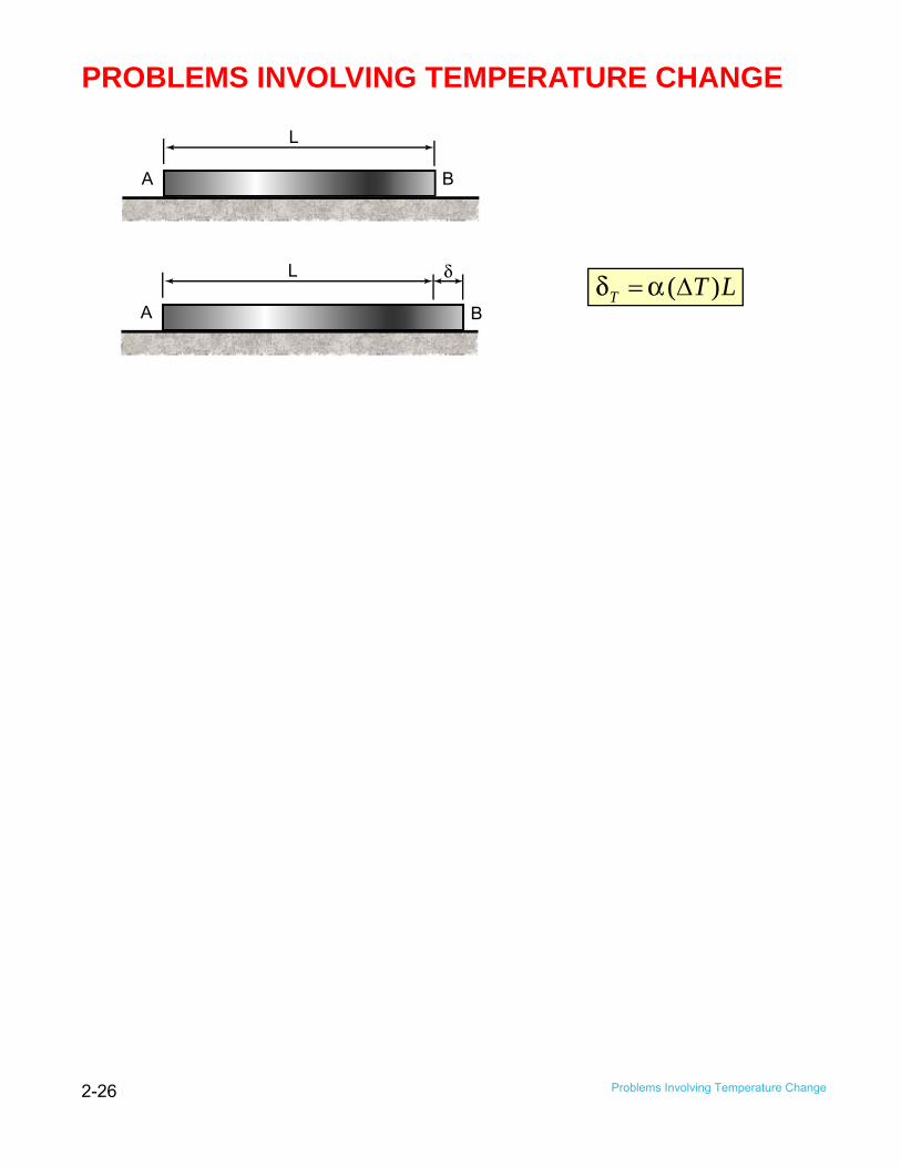
PROBLEMS INVOLVING TEMPERATURE CHANGE
A B
L
A B
L δ ( )T T Lδ α = Δ

2-27
Example The steel rod AB has a diameter of 11 mm and the copper rod BC has a diameter of 7 mm. Determine the displacement of point C if the assembly is subjected to a temperature increase of 50°C. Units: m. Copper: α= 17E-6/ºC Steel: α= 11.7E-6º/C
A B C
1.2 0.8
2-28
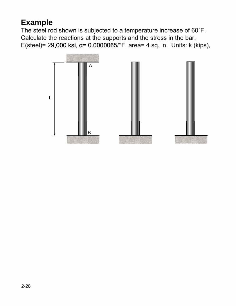
Example The steel rod shown is subjected to a temperature increase of 60˚F. Calculate the reactions at the supports and the stress in the bar. E(steel)= 29,000 ksi, α= 0.0000065/°F, area= 4 sq. in. Units: k (kips),
L
A
B

2-29
Example A solid steel rod S is placed inside a copper pipe C having the same length. The coefficient of thermal expansion of copper is larger than the coefficient of steel. After being assembled, the cylinder and tube are compressed between two rigid plates by forces P. Obtain a formula for the increase in temperature that will cause all of the load to be carried by the copper tube. Units: k (kips), in.
C C
P
P
S

2-30
Cross section
ExampleThe 2.5" diameter aluminum shell is completely bonded to the 1" diameter brass core and is unstressed at 70°F. Determine the stress in each if the temperature is raised to 170°F.Brass: E= 15,000 ksi, α= 11.6E-6/°FAluminum: E= 10,600 ksi, α= 12.9E-6/°F

2-31
Example The square column has an outer shell of brass and inner core of steel. Determine the largest allowable temperature increase if the stress in the steel is not to exceed 55 MPa. Units: mm. E (brass)= 105 GPa, α= 20.9E-6/°C E (steel)= 200 GPa, α= 11.7E-6/°C
500
Column cross-section
5 typ
50

2-32
Example The steel rod AB has a diameter of 11 mm and the copper rod BC has a diameter of 7 mm. Determine the reactions if the assembly is subjected to a temperature increase of 50°C. Units: kN, m. E (copper)= 120 GPa, α= 17E-6/°C E (steel)= 200 GPa, α= 11.7E-6/°C
A B C
1.2 0.8
A B C
A B C

2-33 Poisson’s Ratio
POISSON’S RATIO
P
P
lateral strainaxial strain
ν = −
xy z E
νσ ε ε = = −

2-34 Multiaxial Loading; Generalized Hooke’s Law
MULTIAXIAL LOADING; GENERALIZED HOOKE’S LAW
xσ
yσ
yσ
xσ
zσ yx z
x
yx zy
yx zz
E E E
E E E
E E E
νσ σ νσ ε
σ νσ νσ ε
νσ νσ σ ε
= + − −
= − + −
= − − +

2-35 Shearing Strain
SHEARING STRAIN
xσ
yσ
yσ
xσ
zσ
xy xy
yz yz
zx zx
GGG
τ γ τ γ τ γ
= = =

2-36 Saint-Venant’s Principle
SAINT-VENANT’S PRINCIPLE
P P P P
P
P
P

2-37 Stress Concentrations
STRESS CONCENTRATIONS
P P P P
P P
P
P
P P D
r
1.0
2.0
3.0
K
0.2 0.4 0.6 r/(D-2r)
P P D d
r
K
1.0
2.0
3.0
0 0.10 0.20 0.30 r/d
D/d
1.2 1.3
1.5
1.1
2.0
max
ave
K σ σ
=
W.D. Pilkey, Peterson’s Stress Concentration Factors, 2nd ed., John Wiley and Sons, New York, 1997

2-38
EXAMPLE For the 5 mm thick bar, determine the maximum normal stress for hole diameters 12 mm and 20 mm. Units: kN, mm.
2.5 2.5 60
P P D
r
1.0
2.0
3.0
K
0.2 0.4 0.6 r/(D-2r)
0

2-39
EXAMPLE For the 5 mm thick bar, determine the maximum normal stress for fillet radii of 6 mm and 10 mm. Units: kN, mm.
2.5 2.5 60 40
P P D d
r
K
1.0
2.0
3.0
0 0.10 0.20 0.30 r/d
D/d
1.2 1.3
1.5
1.1
2.0

2-40 Summary
SUMMARY Stress and Strain
Repeated Loadings; Fatigue
Deformation of Members Under Axial Loading
Statically Indeterminate Problems
Temperature Effects
σ
ε
σ
CYCLES
A B C 58
1.2 0.8
100T CΔ = °
A B C 58
1.2 0.8
A B C
1.2 0.8
Eσ ε =
ENDURANCE LIMIT- The stress for which failure does not occur, even for an indefi-nitely large number of loadings.
FATIGUE LIMIT- The stress corresponding to failure after a specified number of loading cycles, such as 500 million.
PLAE
δ =
( )T T Lδ α = Δ

2-41 Summary
Saint-Venants Principle
Stress Concentrations
Shearing Strain
Poisson’s Ratio
Multiaxial Loading; Generalized Hooke’s Law
P
P
xσ
yσ
yσ
xσ
zσ
P P P P
P P P P
xσ
yσ
yσ
xσ
zσ
yx zx
yx zy
yx zz
E E E
E E E
E E E
νσ σ νσ ε
σ νσ νσ ε
νσ νσ σ ε
= + − −
= − + −
= − − +
xy xy
yz yz
zx zx
GGG
τ γ τ γ τ γ
= = =
lateral strainaxial strain
ν = −
max
ave
K σ σ
=