chapter 19: antennas by: james ve3bux. definition the modern dictionary of electronics defines an...
TRANSCRIPT

Chapter 19: Antennas
By: James VE3BUX

2
Definition
The Modern Dictionary of Electronics defines an antenna as:
• That portion, usually wires or rods, of a radio transmitter or receiver station used for radiating waves into or receiving them from space. It changes electrical currents into electromagnetic waves, and vice versa.

3
Basic Electrical Properties
Antennas:• Behave differently based on design• Are (ideally) purely resistive at resonance• Exhibit polarization• Radiate in a predictable pattern• Have an input impedance & exhibit inductive
or capacitive character out of resonance• Have bandwidth

4
Antennas: How important?
• Antennas are the “portal to the ether”• Design and build of antennas are often one of
the most critical aspects of radio communications
• A really well designed and built antenna can work wonders whereas a “wet noodle” or “rubber resistor” antenna are almost entirely useless

5
Antennas: Major design types

6
Antennas: Vertical “Whip”
• Until recently, these were the most prevalent antennas
• Generally used in a vertical arrangement
• Can be multi-band (ie. Cover multiple frequencies without a tuner)
• Omnidirectional

7
Antennas: Dipole (“Doublet”)
• Extremely simple to make & costs very little
• Exhibits some directionality• Can be stacked / arrayed to
increase “gain”• Very common first project• Effectively omnidirectional

8
Antennas: Yagi-Uda
• Directional antenna– Design parameters determine
F/B ratio• Excellent for basic radio
direction finding• Three basic elements:
1. Reflector(s)2. Driven element3. Director(s)
1 2 3

9
Antennas: Cubic Quad
• Directional antenna– Design parameters determine
F/B ratio• Very similar to Yagi-Uda, very
slightly better• Same three basic elements:– Reflector(s)– Driven element– Director(s)

10
Antennas: Magnetic Loop
• Omnidirectional antenna– Does have some directionality
• Reasonably immune to local noise due to principle of operation
• Can generate very significant voltages!
• Very small size

11
Antennas: Dish
• Very directional antenna– Design parameters determine
F/B ratio• Significant “gain” as frequency
increases• Great for E-M-E• Polarized!

12
Antennas: Horn
• Very directional antenna• Generally not used below
10GHz• Polarized!• Extremely efficient (low
radiation resistance)• Can achieve incredible gain
figuresHolmdel Horn

13
Properties: Resistive at Fr
• Antennas are said to behave in a purely resistive manner when they are driven with energy near their resonant point
• This resistive state indicates a good “match” of impedances between the radio and the antenna system
• Recall that when Rload = Rinternal the maximum power transfer occurs– (Table 7-1, p65)

14
Properties: Polarization
• Electromagnetic waves are orthogonal fields which are composed of lines of force which are:– Electric– Magnetic
• Direction of electric field determines polarization– Generally the same direction as the most significant
radiating element

15
Polarization: Importance
• Above HF frequencies, matching polarization becomes extremely important– Loss can be as much as -40dB– Loss = 10log10(cos Θ)2 where Θ = difference angle
• HF propagation makes polarization far less important
• Special types of polarization exist to solve particular challenges– LH or RH Circular

16
Properties: Have radiation pattern
• Antennas radiate their energy differently based on their design
• Radiation pattern is effectively the “shape” of an RF field being generated by a transmitting antenna
• Need a bit more information to discuss patterns…

17
Field Strength
• The strength of a radio signal is defined by the amount of voltage induced onto a second antenna at some distance
• Due to varying types of antennas and their differences in reception, a standard antenna with a length of 1m is used
• Field strength is thus defined to have the unit volts per meter, or v/m– Generally μv/m due to the weak nature of radio signals

18
S-units: An aside
• S-units on a radio are based on 6dB difference– Recall field strength is in volts and therefore the
log math requires 20log10(V1/V2) so 6dB = 2x
• A signal which is said to be “S9” should mean that the receiving antenna would measure 50μv across a 50Ω load (antenna)– Also defined as:• -73dBm for HF• -93dBm for VHF

19
Radiation Pattern: Basics
• To discuss radiation pattern, we need to establish how to present field strength data
•Antenna is placed at the center and where necessary, “elements” are shown on the graph•Concentric rings indicate field strength, usually in a relative sense

20
Radiation Pattern
• The most basic pattern is a so-called isotropic radiator– The antenna radiates energy in all directions “equally
poorly”• Imagine a small sphere at the center of a beach ball– Small sphere at the center is the antenna– Beach ball is the shape that the radiated energy will take
in ideal conditions– The surface of the ball is EM energy - as the radius
increases, the “thickness” of the ball decreases; think of the EM field magnitude as the thickness• Inverse square law

21
Radiation Patterns: Dipole
• Dipole antennas are the first to exhibit directivity
• Imagine a wire antenna which is vertical, the energy radiates as shown:

22
Radiation Patterns: Vertical
• Simple ground mounted 1/4λ monopole (vertical) antenna
• Good “take-off” angle provides DX opportunities
• Ground conductance becomes important and will affect pattern– Antennas of this nature generally rely on (or are
significantly enhanced with) the presence of “ground radials” which serves as a distributed ground plane
23
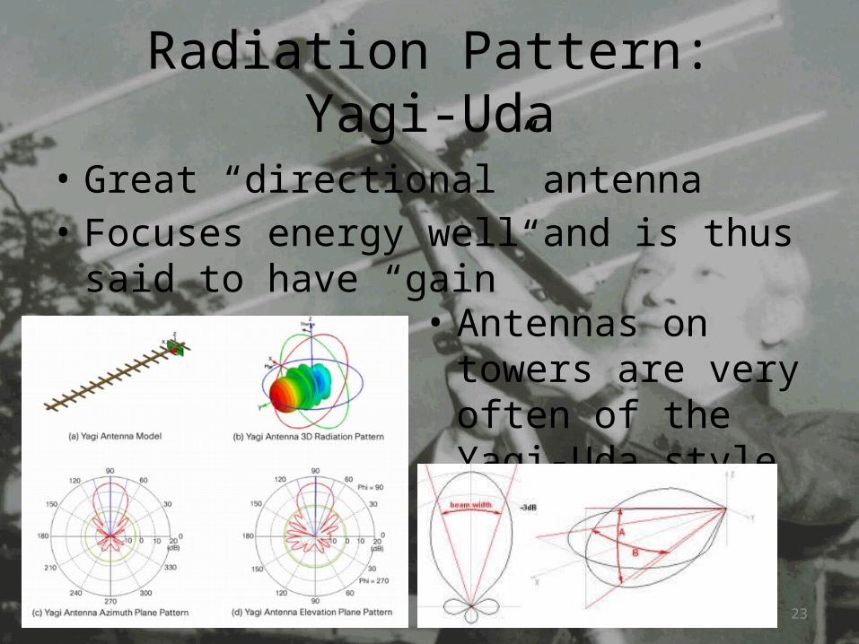
Radiation Pattern: Yagi-Uda
• Great “directional” antenna• Focuses energy well and is thus said to have
“gain”• Antennas on towers
are very often of the Yagi-Uda style

24
Input Impedance: Design & Location
• Antenna impedance depends on a few factors:– Design– Height above ground– Resonant frequency
• Matching 50Ω output of radio to the antenna’s impedance is important– Ideal power transfer– Reduce wasted energy coming back as reflected
power (SWR)

25
Impedance: DesignAntenna Type Free-space impedance (Ω)
Yagi (direct feed) 20-25
1/4λ vertical (whip) 37
Dipole (Inverted V) ~50
Dipole (Basic Design) 73
Cubic Quad 115
Dipole (Folded Design) 300
Windom (Off-center fed dipole) 600+
• Plenty of ways to match the radio to the antenna• Matching networks (“tuners”) are often the solution

26
Properties: Bandwidth
• Antennas have a resonant point due to electrical length of elements• As you move away from the resonant point, the impedance changes

27
Properties: Bandwidth
• Some parameters which affect bandwidth are:– Physical design of antenna (dipole vs Yagi, etc)– Antenna element diameter– Environment around antenna– Feedline losses– Shortening / “Loading” of antenna
• Bandwidth edges are generally defined by 2:1 SWR points (similar to -3dB concept)

28
• Questions?