chapter 16 bulk forming processes (part 2: extrusion & drawing) (review) ein 3390 manufacturing...
TRANSCRIPT
Chapter 16Chapter 16
Bulk Forming ProcessesBulk Forming Processes(Part 2: Extrusion & Drawing)(Part 2: Extrusion & Drawing)
(Review)(Review)
EIN 3390 Manufacturing ProcessesEIN 3390 Manufacturing ProcessesSummer A, 2011Summer A, 2011
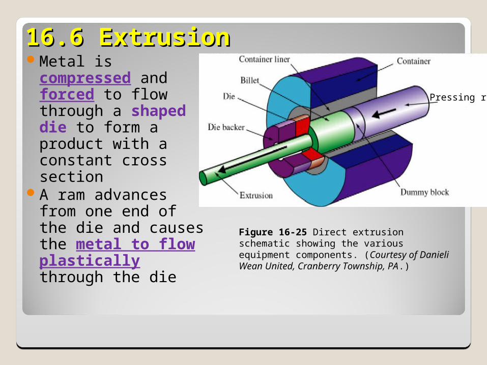
16.6 Extrusion16.6 ExtrusionMetal is
compressed and forced to flow through a shaped die to form a product with a constant cross section
A ram advances from one end of the die and causes the metal to flow plastically through the die
Figure 16-25 Direct extrusion schematic showing the various equipment components. (Courtesy of Danieli Wean United, Cranberry Township, PA.)
Pressing ram
ExtrusionExtrusionDefinition:
◦Process of forcing a billet through a die above its elastic limit, taking shape of the opening.
Purpose:◦To reduce its cross-section or to produce a solid or hollow cross section.
Analogy: “Like squeezing toothpaste out of a tube”.
ExtrusionExtrusionExtruded products always have a constant cross-
section.
It can be a semi-continuous or a batch process.
Extrusions can be cut into lengths to become discrete parts like gears, brackets, etc.
A billet can also extruded individually in a chamber, and produces discrete parts.
Typical products: railings, tubing, structural shapes, etc.
ExtrusionExtrusionCan be performed at elevated temperatures or
room temperatures, depending on material ductility.
Commonly extruded materials include aluminum, magnesium (low yield strength materials), copper, and lead.
Steels and nickel based alloys are far more difficult to extrude (high yield strength materials).
Lubricants are essential to extrude high strength alloys to avoid tendency of material to weld to die walls.
Advantages of ExtrusionAdvantages of Extrusion
Many shapes can be produced that are not possible with rolling
No draft is requiredAmount of reduction in a single step is
only limited by the equipment, not the material or the design
Dies are relatively inexpensiveSmall quantities of a desired shape can
be produced economically
Extrusion MethodsExtrusion Methods
Methods of extrusion:◦Hot extrusion is usually done by either the direct or
indirect methods.
◦Direct extrusion Solid ram drives the entire billet to and through a
stationary die Must provide additional power to overcome friction
between billet surface and die walls
Extrusion MethodsExtrusion Methods◦Indirect extrusion
A hollow ram pushes the die back through a stationary, confined billet
No relative motion and no friction between billet and die walls.
Lower forces required, can extrude longer billets.
More complex process, more expensive equipment required.
Extrusion MethodsExtrusion Methods
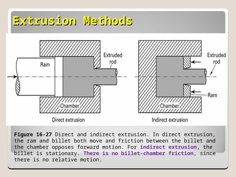
Figure 16-27 Direct and indirect extrusion. In direct extrusion, the ram and billet both move and friction between the billet and the chamber opposes forward motion. For indirect extrusion, the billet is stationary. There is no billet-chamber friction, since there is no relative motion.
Variables in ExtrusionVariables in Extrusion
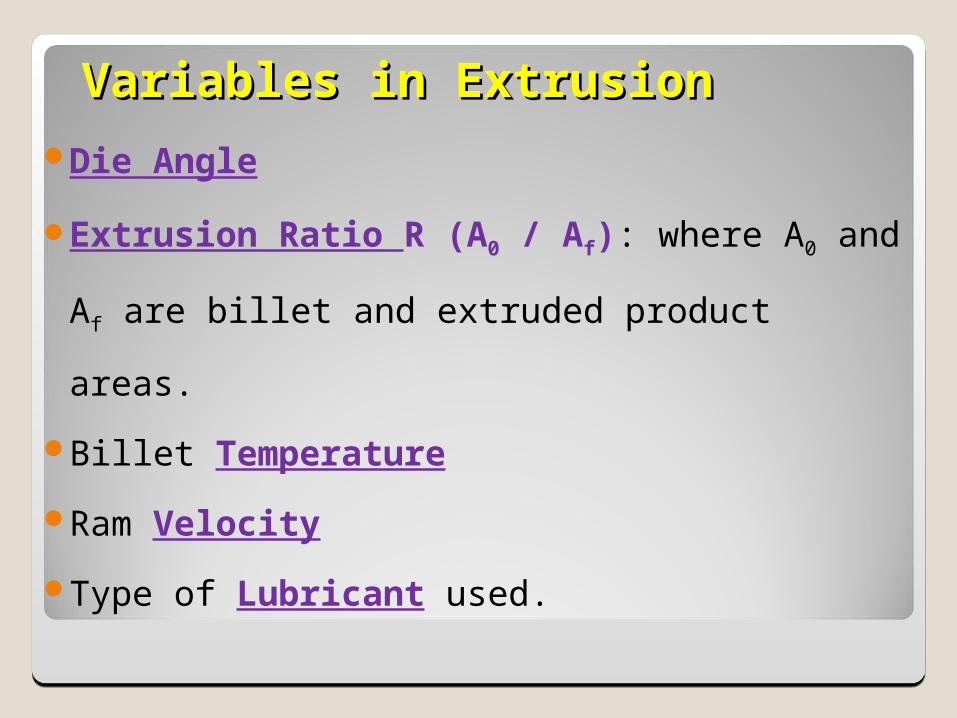
Die Angle
Extrusion Ratio R (A0 / Af): where A0 and
Af are billet and extruded product areas.
Billet Temperature
Ram Velocity
Type of Lubricant used.
Variables in ExtrusionVariables in Extrusion
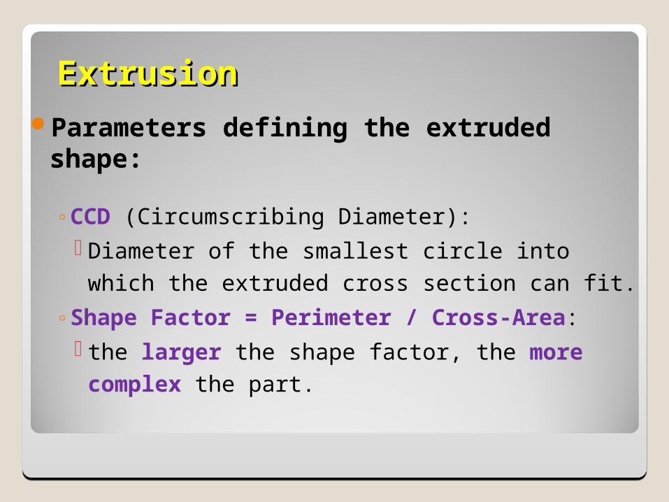
ExtrusionExtrusionParameters defining the extruded
shape:
◦CCD (Circumscribing Diameter): Diameter of the smallest circle into which the extruded cross section can fit.
◦Shape Factor = Perimeter / Cross-Area: the larger the shape factor, the more complex the part.
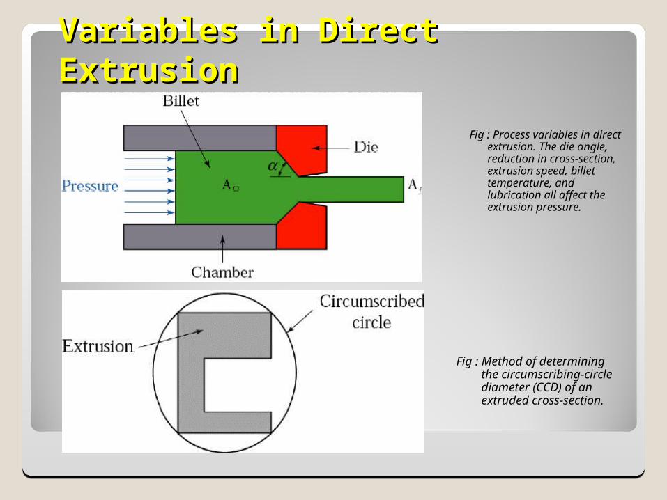
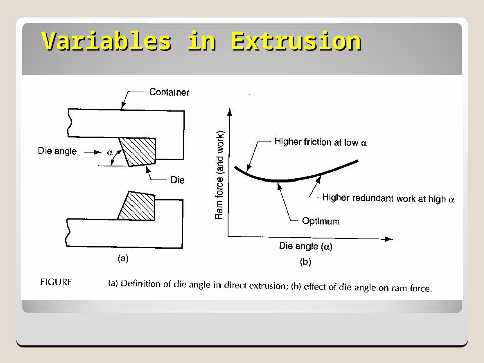
Fig : Process variables in direct extrusion. The die angle, reduction in cross-section, extrusion speed, billet temperature, and lubrication all affect the extrusion pressure.
Fig : Method of determining the circumscribing-circle diameter (CCD) of an extruded cross-section.
Variables in Direct ExtrusionVariables in Direct Extrusion
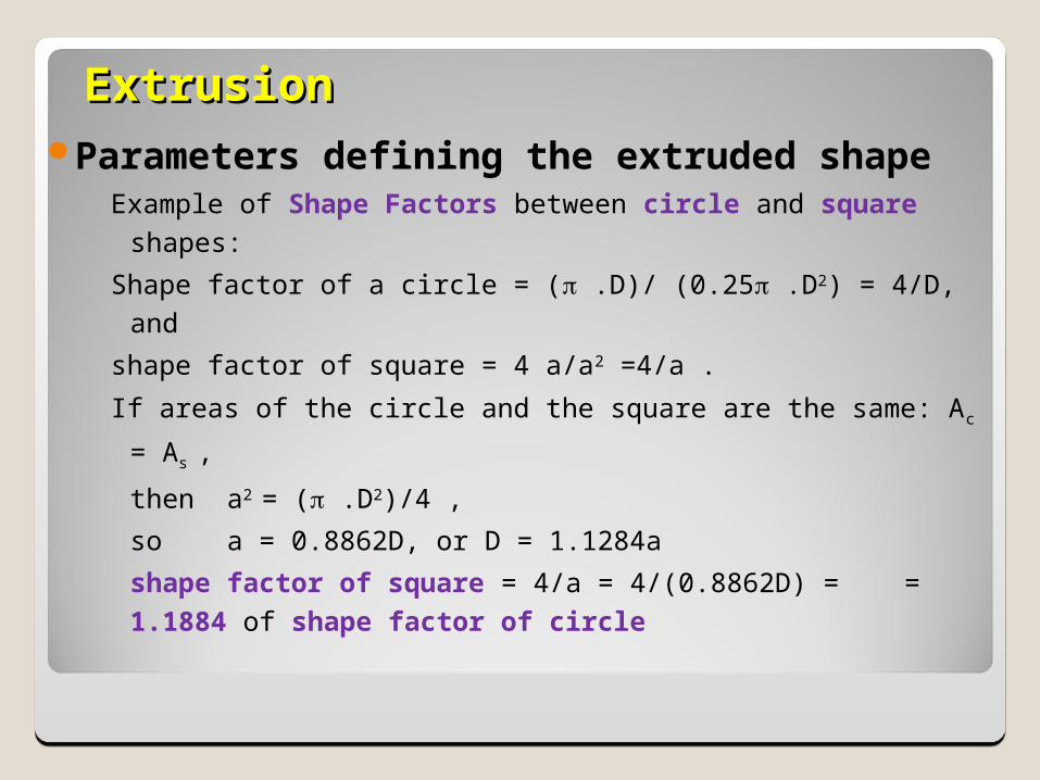
ExtrusionExtrusionParameters defining the extruded
shapeExample of Shape Factors between circle and square
shapes:
Shape factor of a circle = ( .D)/ (0.25 .D2) = 4/D, and
shape factor of square = 4 a/a2 =4/a .
If areas of the circle and the square are the same: Ac = As ,
then a2 = ( .D2)/4 ,
so a = 0.8862D, or D = 1.1284a
shape factor of square = 4/a = 4/(0.8862D) = = 1.1884 of shape factor of circle
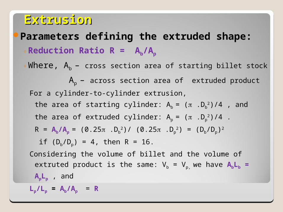
ExtrusionExtrusionParameters defining the extruded shape:
◦Reduction Ratio R = Ab/Ap
◦Where, Ab – cross section area of starting billet stock
Ap – across section area of extruded product
For a cylinder-to-cylinder extrusion,
the area of starting cylinder: Ab = ( .Db2)/4 , and
the area of extruded cylinder: Ap = ( .Dp2)/4 .
R = Ab/Ap = (0.25 .Db2)/ (0.25 .Dp
2) = (Db/Dp)2
if (Db/Dp) = 4, then R = 16.
Considering the volume of billet and the volume of extruted
product is the same: Vb = Vp, we have AbLb = ApLp , and
Lp/Lp = Ab/Ap = R
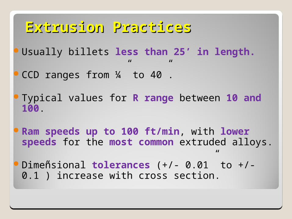
Extrusion PracticesExtrusion PracticesUsually billets less than 25’ in length.
CCD ranges from ¼” to 40”.
Typical values for R range between 10 and 100.
Ram speeds up to 100 ft/min, with lower speeds for the most common extruded alloys.
Dimensional tolerances (+/- 0.01” to +/- 0.1”) increase with cross section.
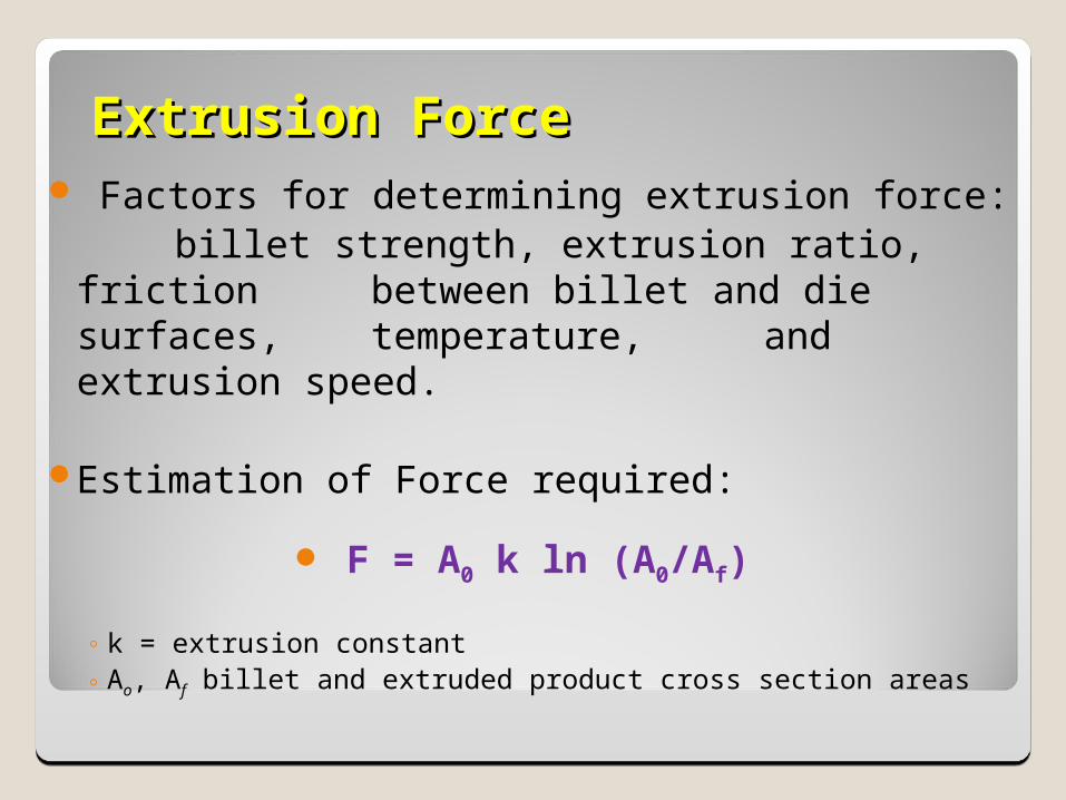
Extrusion ForceExtrusion Force Factors for determining extrusion force:
billet strength, extrusion ratio, friction between billet and die surfaces,
temperature, and extrusion speed.
Estimation of Force required:
F = A0 k ln (A0/Af)
◦ k = extrusion constant ◦ Ao, Af billet and extruded product cross section areas
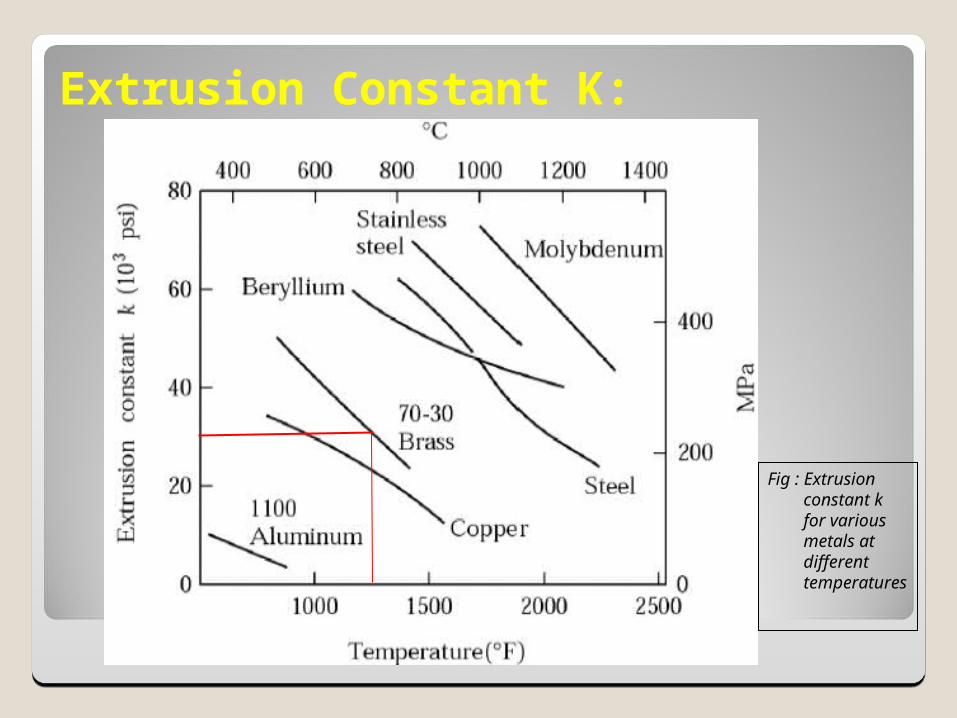
Extrusion Constant K:
Fig : Extrusion constant k for various metals at different temperatures
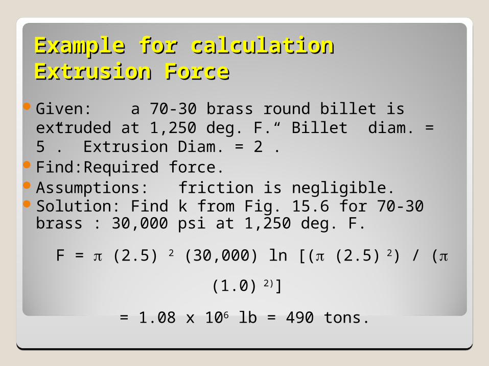
Example for calculation Example for calculation Extrusion Force Extrusion Force
Given: a 70-30 brass round billet is extruded at 1,250 deg. F.
Billet diam. = 5”. Extrusion Diam. = 2”.
Find: Required force.Assumptions: friction is negligible.Solution: Find k from Fig. 15.6 for 70-30
brass : 30,000 psi at 1,250 deg. F.
F = (2.5) 2 (30,000) ln [( (2.5) 2) / ( (1.0) 2)]
= 1.08 x 10⁶ lb = 490 tons.
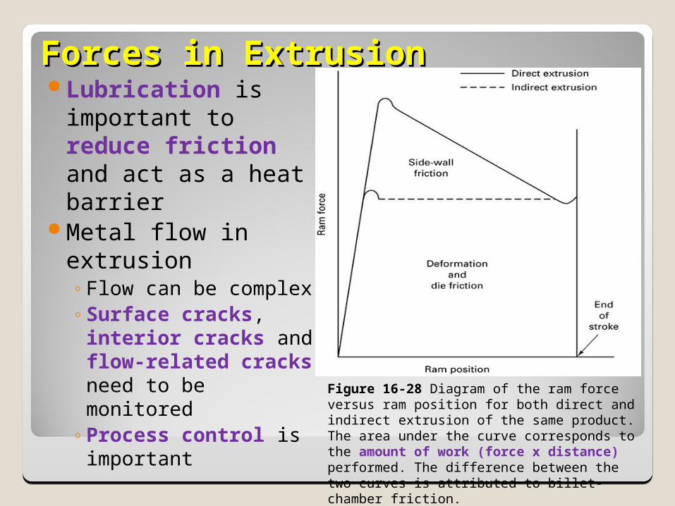
Forces in ExtrusionForces in ExtrusionLubrication is
important to reduce friction and act as a heat barrier
Metal flow in extrusion◦Flow can be complex◦Surface cracks,
interior cracks and flow-related cracks need to be monitored
◦Process control is important
Figure 16-28 Diagram of the ram force versus ram position for both direct and indirect extrusion of the same product. The area under the curve corresponds to the amount of work (force x distance) performed. The difference between the two curves is attributed to billet-chamber friction.
LubricationLubricationAn acceptable lubricant is expected to
1) reduce friction, and2) act as a barrier to heat transfer at all stages of the process.
Metal FlowMetal FlowQuite complex.Impact quality and mechanical properties of
product: must not overlook to prevent defects.Extruded products have elongated grain
structure.◦Metal at center passes through die w/little distortion
◦Metal near surface undergoes considerable shearing.
◦Friction between moving billet and stationary chamber walls impedes surface flow.
◦Result is deformation pattern
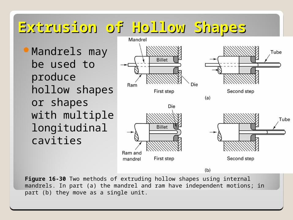
Extrusion of Hollow ShapesExtrusion of Hollow ShapesMandrels may
be used to produce hollow shapes or shapes with multiple longitudinal cavities
Figure 16-30 Two methods of extruding hollow shapes using internal mandrels. In part (a) the mandrel and ram have independent motions; in part (b) they move as a single unit.
Extrusion MethodsExtrusion MethodsIn Hydrostatic Extrusion:
◦The chamber, which is larger than the billet, is filled with a fluid.
◦The fluid is compressed with the ram and pushes the billet forward.
◦Benefit: no friction to overcome along sides of chamber.
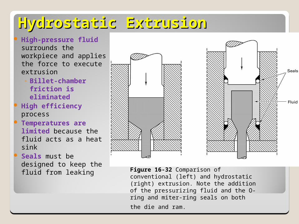
Hydrostatic ExtrusionHydrostatic Extrusion High-pressure fluid
surrounds the workpiece and applies the force to execute extrusion◦ Billet-chamber
friction is eliminated
High efficiency process
Temperatures are limited because the fluid acts as a heat sink
Seals must be designed to keep the fluid from leaking Figure 16-32 Comparison of conventional (left)
and hydrostatic (right) extrusion. Note the addition of the pressurizing fluid and the O-ring
and miter-ring seals on both the die and ram.
Extrusion can be Hot or ColdExtrusion can be Hot or ColdHot Extrusion
◦Takes place at elevated temperatures.◦Used in metals that have low ductility at room temperature.
◦Need to pre-heat dies to prolong die life and reduce billet cooling.
◦Hot working tends to develop an oxide film on the outside of the work unless done in an inert environment.
◦Solution: place smaller-diameter dummy block ahead of ram before
the billet. A layer of oxidized material is then left in the chamber, and is later removed and final part is free of oxides.

Extrusion can be Hot or ColdExtrusion can be Hot or ColdCold Extrusion (also know as Impact
Extrusion)◦Designated as cold when combined with other forging
operations. ◦Slugs having less than 1.5” diam. are sheared / ends
ground; larger slugs are machined.◦Punch descends on a blank, which is extruded
backward.◦Slug dimensions and material, as well as lubrication
are key variables. ◦Diameters up to 6” and thin walls can be made.◦Collapsible tubes can be made this way (toothpaste
tubes).
Advantages Cold vs. Hot Advantages Cold vs. Hot ExtrusionExtrusion
Cold:◦Better mechanical properties due to work-
hardening.◦Good dimensional tolerances & surface finish.◦No need to heat billet.◦Competitive production rates & costs.
Hot:◦Larger variety of materials.◦Less forces required.◦Better material flow.
Guidelines for Die DesignGuidelines for Die DesignAvoid sharp corners
Have similarly sized voids if possible.
Have even thickness in walls if possible.
Have even flow.
Defects in ExtrusionsDefects in ExtrusionsSurface Cracking / Tearing
◦Occurs with high friction or speed.
◦Can also occur with sticking of billet material on die land.
◦Material sticks, pressure increases, product stops and starts to move again.
◦This produces circumferential cracks on surface, similar to a bamboo stem.
Defects in ExtrusionsDefects in Extrusions
Internal Cracking◦Center of extrusion tends to develop cracks of
various shapes.◦Center, center-burst, and arrowhead◦Center cracking:
◦Increases with increasing die angle.◦Increases with impurities.◦Decreases with increasing R and friction.
DrawingDrawingDefinition
◦Cross section of a round rod / wire is reduced by pulling it through a die.
Variables:◦Die Angle, Extrusion Ratio R (A0 / Af) , Friction between die and workpiece, drawing speed.
“There is an optimum angle at which the drawing force is minimum” for a given diameter reduction and friction parameter.
DrawingDrawing
Estimation of Drawing Force required:
F = Yavg Af ln (A0/Af)
Yavg = average true stress of material in the die gap.
Assumptions: no friction.
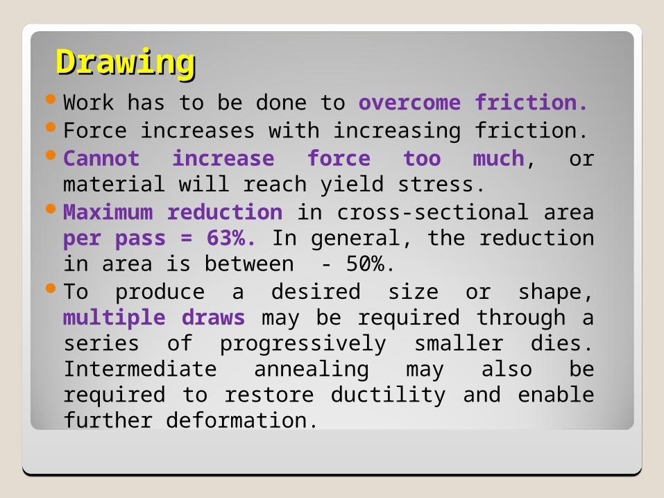
DrawingDrawingWork has to be done to overcome friction.Force increases with increasing friction.Cannot increase force too much, or
material will reach yield stress.Maximum reduction in cross-sectional area
per pass = 63%. In general, the reduction in area is between - 50%.
To produce a desired size or shape, multiple draws may be required through a series of progressively smaller dies. Intermediate annealing may also be required to restore ductility and enable further deformation.
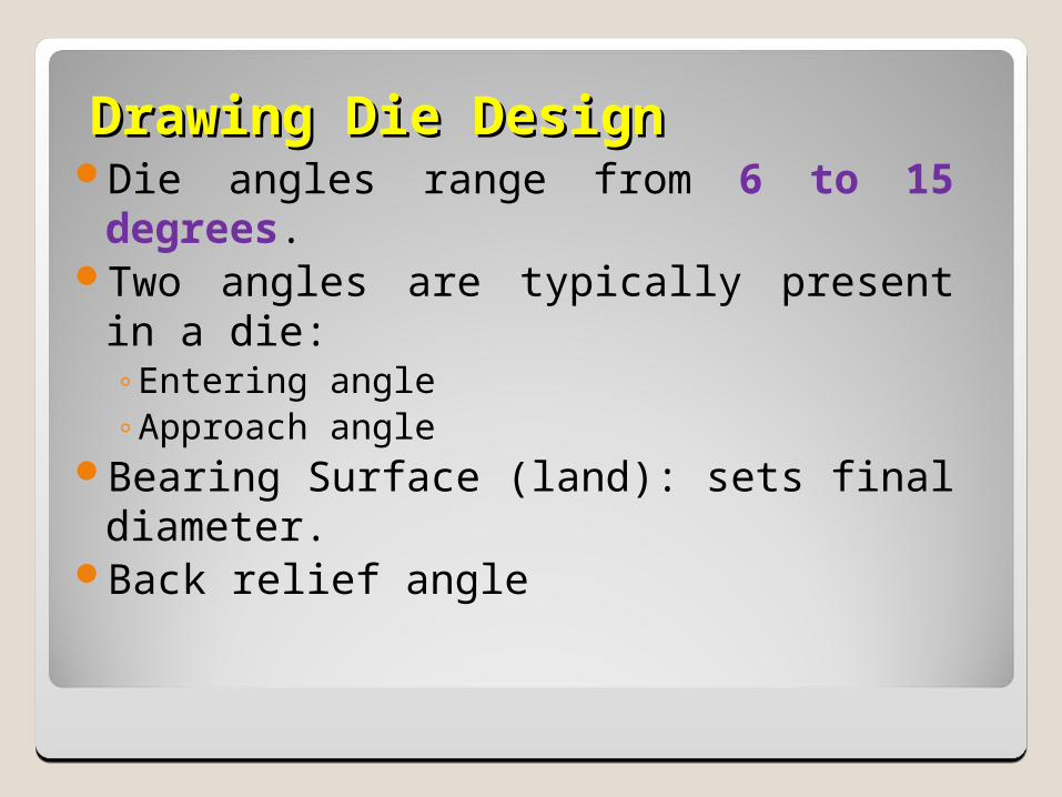
Drawing Die DesignDrawing Die DesignDie angles range from 6 to 15
degrees.Two angles are typically present in a
die:◦Entering angle◦Approach angle
Bearing Surface (land): sets final diameter.
Back relief angle
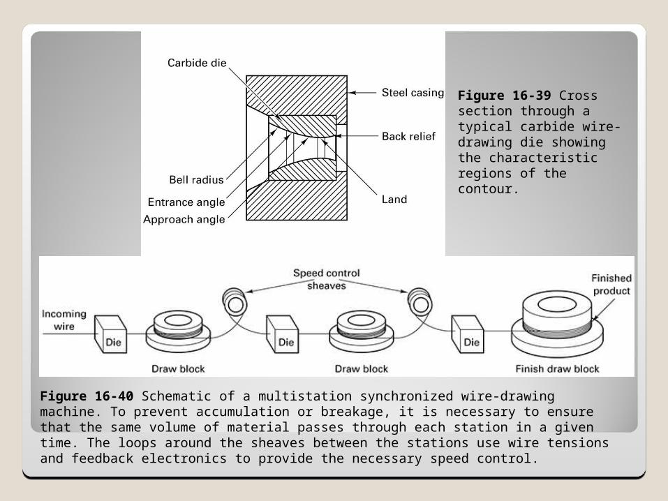
Figure 16-40 Schematic of a multistation synchronized wire-drawing machine. To prevent accumulation or breakage, it is necessary to ensure that the same volume of material passes through each station in a given time. The loops around the sheaves between the stations use wire tensions and feedback electronics to provide the necessary speed control.
Figure 16-39 Cross section through a typical carbide wire-drawing die showing the characteristic regions of the contour.
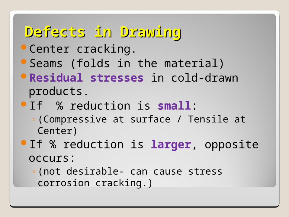
Defects in DrawingDefects in DrawingCenter cracking.Seams (folds in the material)Residual stresses in cold-drawn
products.If % reduction is small:
◦(Compressive at surface / Tensile at Center)If % reduction is larger, opposite
occurs:◦(not desirable- can cause stress corrosion
cracking.)
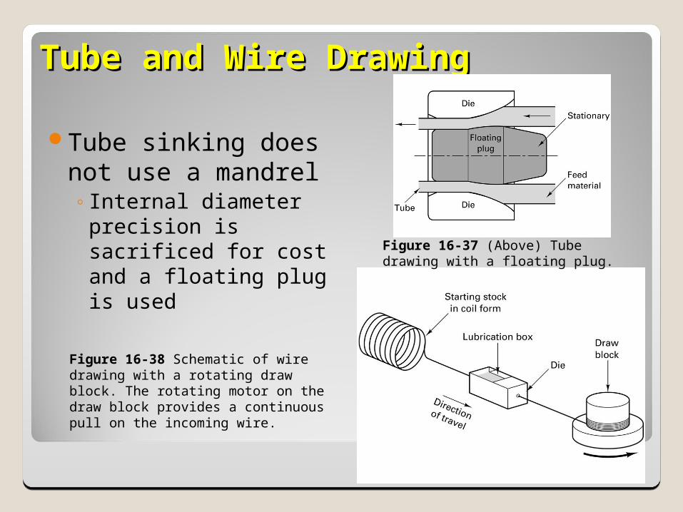
Tube and Wire DrawingTube and Wire Drawing
Tube sinking does not use a mandrel◦Internal diameter
precision is sacrificed for cost and a floating plug is used
Figure 16-37 (Above) Tube drawing with a floating plug.
Figure 16-38 Schematic of wire drawing with a rotating draw block. The rotating motor on the draw block provides a continuous pull on the incoming wire.
16.8 Cold Forming and Impact 16.8 Cold Forming and Impact ExtrusionExtrusion
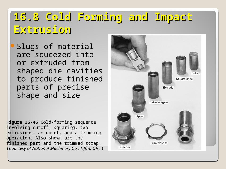
Slugs of material are squeezed into or extruded from shaped die cavities to produce finished parts of precise shape and size
Figure 16-46 Cold-forming sequence involving cutoff, squaring, two extrusions, an upset, and a trimming operation. Also shown are the finished part and the trimmed scrap. (Courtesy of National Machinery Co., Tiffin, OH.)
16.8 Cold Forming and Impact 16.8 Cold Forming and Impact ExtrusionExtrusion
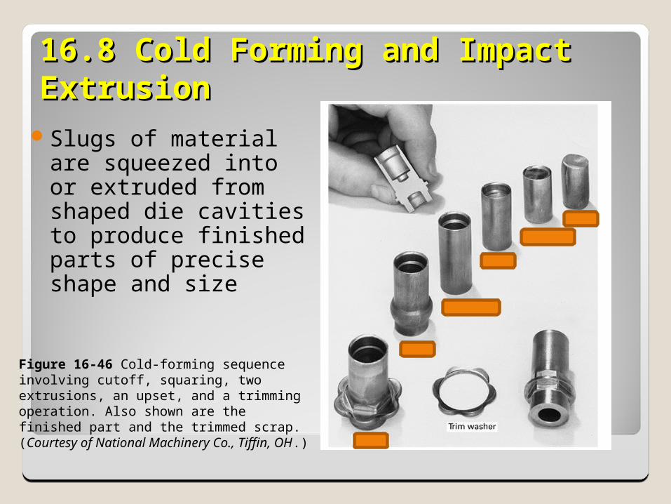
Slugs of material are squeezed into or extruded from shaped die cavities to produce finished parts of precise shape and size
Figure 16-46 Cold-forming sequence involving cutoff, squaring, two extrusions, an upset, and a trimming operation. Also shown are the finished part and the trimmed scrap. (Courtesy of National Machinery Co., Tiffin, OH.)
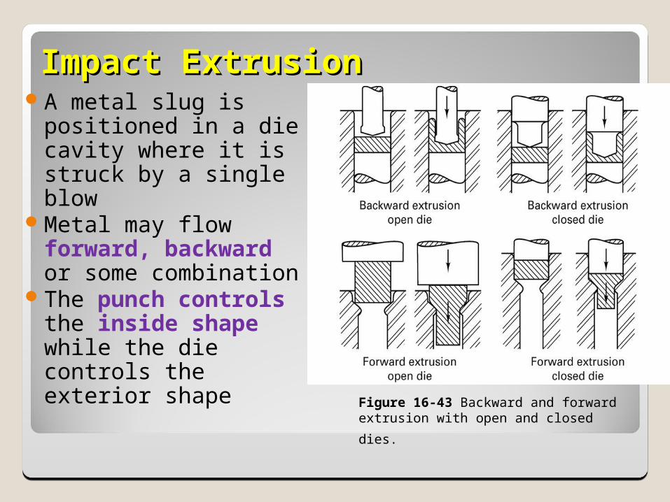
ImpactImpact ExtrusionExtrusionA metal slug is
positioned in a die cavity where it is struck by a single blow
Metal may flow forward, backward or some combination
The punch controls the inside shape while the die controls the exterior shape
Figure 16-43 Backward and forward extrusion
with open and closed dies.
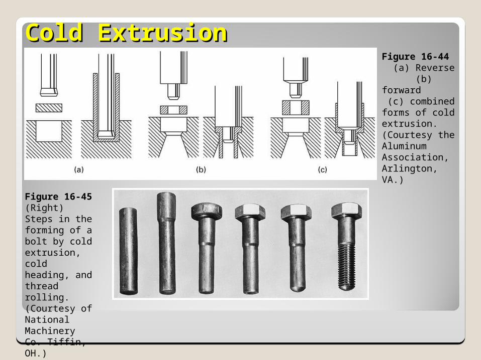
Cold ExtrusionCold Extrusion
Figure 16-45 (Right) Steps in the forming of a bolt by cold extrusion, cold heading, and thread rolling. (Courtesy of National Machinery Co. Tiffin, OH.)
Figure 16-44 (a) Reverse (b) forward (c) combined forms of cold extrusion. (Courtesy the Aluminum Association, Arlington, VA.)

SummarySummary
There are a variety of bulk deformation processes
The main processes are rolling, forging, extrusion, and drawing
Each has limits and advantages as to its capabilities
The correct process depends on the desired shape, surface finish, quantity, etc.
HW HW (Not required to turn in)(Not required to turn in)
Review questions (page 418):40, 42, 45, 51
Problems (page 418 – 419): 2: a, b, c, d