chapter 15 – multiprocessor management - virginia...
TRANSCRIPT
1
2004 Deitel & Associates, Inc. All rights reserved.
Chapter 15 – Multiprocessor Management
Outline15.1 Introduction15.2 Multiprocessor Architecture15.2.1 Classifying Sequential and Parallel Architectures15.2.2 Processor Interconnection Schemes15.2.3 Loosely Coupled vs. Tightly Coupled Systems15.3 Multiprocessor Operating System Organizations15.3.1 Master/Slave15.3.2 Separate Kernels15.3.3 Symmetrical Organization15.4 Memory Access Architectures15.4.1 Uniform Memory Access15.4.2 Nonuniform Memory Access15.4.3 Cache-Only Memory Architecture15.4.4 No Remote Memory Access15.5 Multiprocessor Memory Sharing15.5.1 Cache Coherence15.5.2 Page Replication and Migration15.5.3 Shared Virtual Memory
2004 Deitel & Associates, Inc. All rights reserved.
Chapter 15 – Multiprocessor Management
Outline (continued)15.6 Multiprocessor Scheduling15.6.1 Job-Blind Multiprocessor Scheduling15.6.2 Job-Aware Multiprocessor Scheduling15.7 Process Migration15.7.1 Flow of Process Migration15.7.2 Process Migration Concepts15.7.3 Process Migration Strategies15.8 Load Balancing15.8.1 Static Load Balancing15.8.2 Dynamic Load Balancing15.9 Multiprocessor Mutual Exclusion15.9.1 Spin Locks15.9.2 Sleep/Wakeup Locks15.9.3 Read/Write Locks

2
2004 Deitel & Associates, Inc. All rights reserved.
Objectives
• After reading this chapter, you should understand:– multiprocessor architectures and operating system organizations.– multiprocessor memory architectures.– design issues specific to multiprocessor environments.– algorithms for multiprocessor scheduling.– process migration in multiprocessor systems.– load balancing in multiprocessor systems.– mutual exclusion techniques for multiprocessor systems.
2004 Deitel & Associates, Inc. All rights reserved.
15.1 Introduction
• Multiprocessor system – Computer that contains more than one processor– Benefits
• Increased processing power• Scale resource use to application requirements
– Additional operating system responsibilities• All processors remain busy• Even distribution of processes throughout the system• All processors work on consistent copies of shared data• Execution of related processes synchronized• Mutual exclusion enforced
3
2004 Deitel & Associates, Inc. All rights reserved.
15.2 Multiprocessor Architecture
• Examples of multiprocessors– Dual-processor personal computer– Powerful server containing many processors– Cluster of workstations
• Classifications of multiprocessor architecture– Nature of datapath– Interconnection scheme– How processors share resources
2004 Deitel & Associates, Inc. All rights reserved.
15.2.1 Classifying Sequential and Parallel Architectures
• Stream: sequence of bytes– Data stream– Instruction stream
• Flynn’s classifications– Single-instruction-stream, single-data-stream (SISD) computers
• Typical uniprocessors• Parallelism through pipelines, superscalar, VLIW, HT-technology
– Multiple-instruction-stream, single-data-stream (MISD) computers• Not used often
– Single-instruction-stream, multiple-data-stream (SIMD) computers• Vector and array processors
– Multiple-instruction-stream, multiple-data-stream (MIMD) computers• Multiprocessors
4
2004 Deitel & Associates, Inc. All rights reserved.
15.2.2 Processor Interconnection Schemes
• Interconnection scheme– Describes how the system’s components, such as processors and
memory modules, are connected– Consists of nodes (components or switches) and links
(connections)– Parameters used to evaluate interconnection schemes
• Node degree• Bisection width• Network diameter• Cost of the interconnection scheme
2004 Deitel & Associates, Inc. All rights reserved.
15.2.2 Processor Interconnection Schemes
• Shared bus– Single communication path between all nodes– Contention can build up for shared bus– Fast for small multiprocessors– Form supernodes by connecting several components with a
shared bus; use a more scalable interconnection scheme to connect supernodes
– Dual-processor Intel Pentium
5
2004 Deitel & Associates, Inc. All rights reserved.
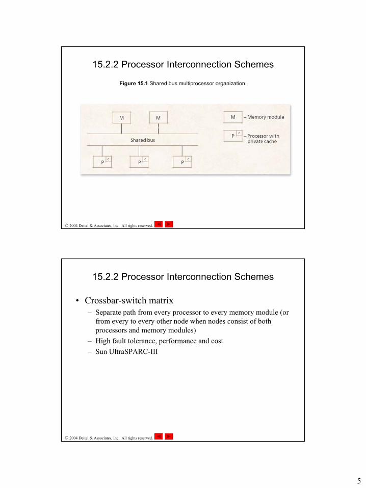
Figure 15.1 Shared bus multiprocessor organization.
15.2.2 Processor Interconnection Schemes
2004 Deitel & Associates, Inc. All rights reserved.
15.2.2 Processor Interconnection Schemes
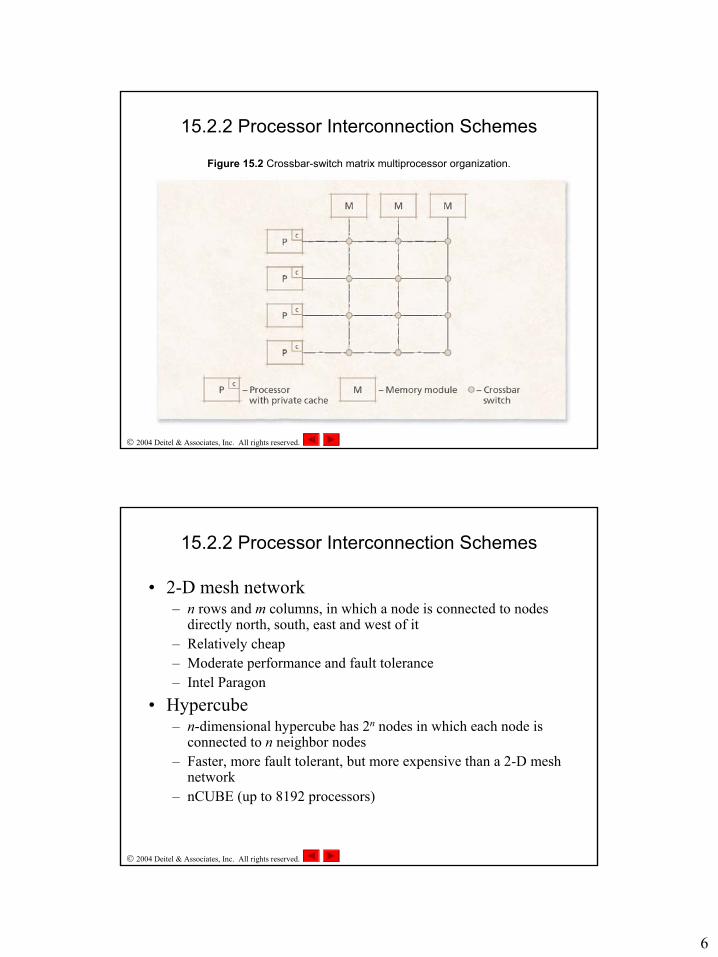
• Crossbar-switch matrix– Separate path from every processor to every memory module (or
from every to every other node when nodes consist of both processors and memory modules)
– High fault tolerance, performance and cost– Sun UltraSPARC-III
6
2004 Deitel & Associates, Inc. All rights reserved.
Figure 15.2 Crossbar-switch matrix multiprocessor organization.
15.2.2 Processor Interconnection Schemes
2004 Deitel & Associates, Inc. All rights reserved.
15.2.2 Processor Interconnection Schemes
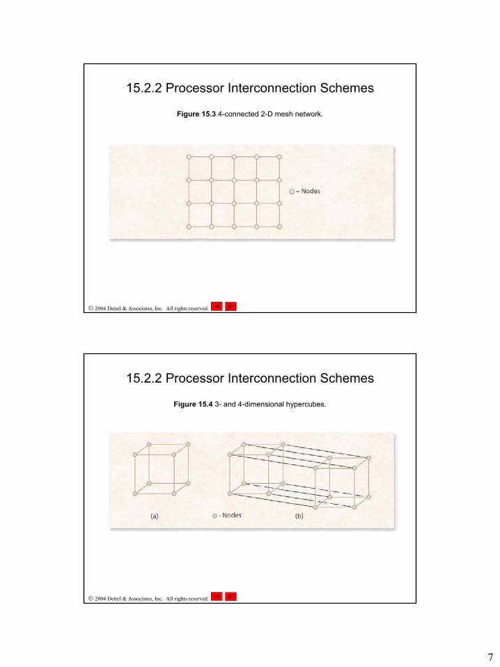
• 2-D mesh network– n rows and m columns, in which a node is connected to nodes
directly north, south, east and west of it– Relatively cheap– Moderate performance and fault tolerance– Intel Paragon
• Hypercube– n-dimensional hypercube has 2n nodes in which each node is
connected to n neighbor nodes– Faster, more fault tolerant, but more expensive than a 2-D mesh
network– nCUBE (up to 8192 processors)
7
2004 Deitel & Associates, Inc. All rights reserved.
Figure 15.3 4-connected 2-D mesh network.
15.2.2 Processor Interconnection Schemes
2004 Deitel & Associates, Inc. All rights reserved.
Figure 15.4 3- and 4-dimensional hypercubes.
15.2.2 Processor Interconnection Schemes
8
2004 Deitel & Associates, Inc. All rights reserved.
15.2.2 Processor Interconnection Schemes
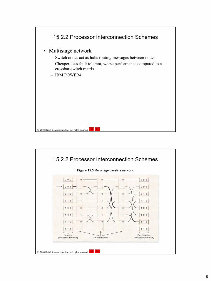
• Multistage network– Switch nodes act as hubs routing messages between nodes– Cheaper, less fault tolerant, worse performance compared to a
crossbar-switch matrix– IBM POWER4
2004 Deitel & Associates, Inc. All rights reserved.
Figure 15.5 Multistage baseline network.
15.2.2 Processor Interconnection Schemes

9
2004 Deitel & Associates, Inc. All rights reserved.
15.2.3 Loosely Coupled vs. Tightly Coupled Systems
• Tightly coupled systems– Processors share most resources including memory– Communicate over shared buses using shared physical memory
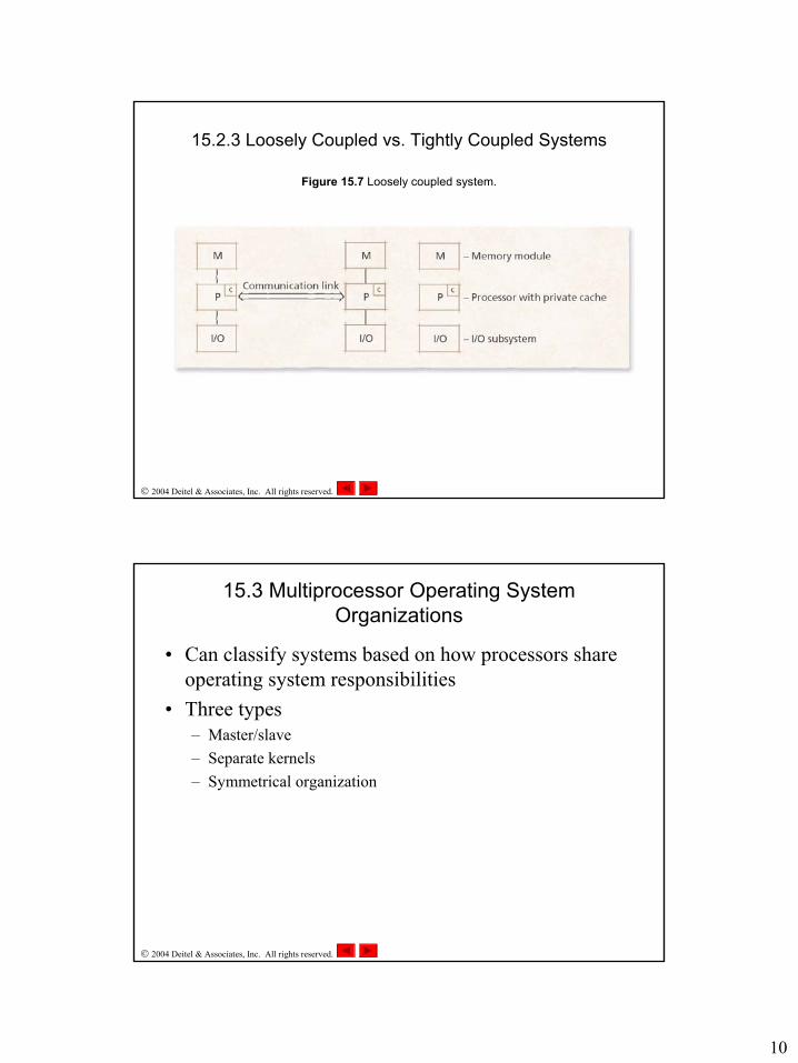
• Loosely coupled systems– Processors do not share most resources– Most communication through explicit messages or shared virtual
memory (although not shared physical memory)
• Comparison– Loosely coupled systems: more flexible, fault tolerant, scalable– Tightly coupled systems: more efficient, less burden to operating
system programmers
2004 Deitel & Associates, Inc. All rights reserved.
Figure 15.6 Tightly coupled system.
15.2.3 Loosely Coupled vs. Tightly Coupled Systems
10
2004 Deitel & Associates, Inc. All rights reserved.
Figure 15.7 Loosely coupled system.
15.2.3 Loosely Coupled vs. Tightly Coupled Systems
2004 Deitel & Associates, Inc. All rights reserved.
15.3 Multiprocessor Operating System Organizations
• Can classify systems based on how processors share operating system responsibilities
• Three types– Master/slave– Separate kernels– Symmetrical organization
11
2004 Deitel & Associates, Inc. All rights reserved.
15.3.1 Master/Slave
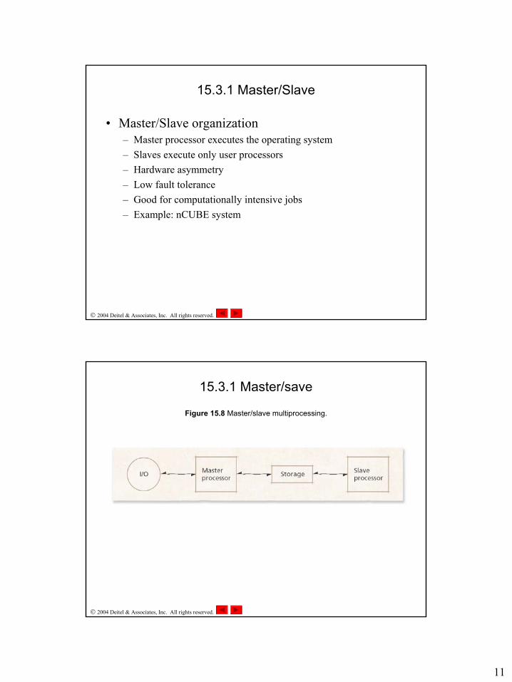
• Master/Slave organization– Master processor executes the operating system– Slaves execute only user processors– Hardware asymmetry– Low fault tolerance– Good for computationally intensive jobs– Example: nCUBE system
2004 Deitel & Associates, Inc. All rights reserved.
Figure 15.8 Master/slave multiprocessing.
15.3.1 Master/save
12
2004 Deitel & Associates, Inc. All rights reserved.
15.3.2 Separate Kernels
• Separate kernels organization– Each processor executes its own operating system– Some globally shared operating system data– Loosely coupled– Catastrophic failure unlikely, but failure of one processor results
in termination of processes on that processor– Little contention over resources– Example: Tandem system
2004 Deitel & Associates, Inc. All rights reserved.
15.3.3 Symmetrical Organization
• Symmetrical organization– Operating system manages a pool of identical processors– High amount of resource sharing– Need for mutual exclusion– Highest degree of fault tolerance of any organization– Some contention for resources– Example: BBN Butterfly
13
2004 Deitel & Associates, Inc. All rights reserved.
15.4 Memory Access Architectures
• Memory access– Can classify multiprocessors based on how processors share
memory– Goal: Fast memory access from all processors to all memory
• Contention in large systems makes this impractical
2004 Deitel & Associates, Inc. All rights reserved.
15.4.1 Uniform Memory Access
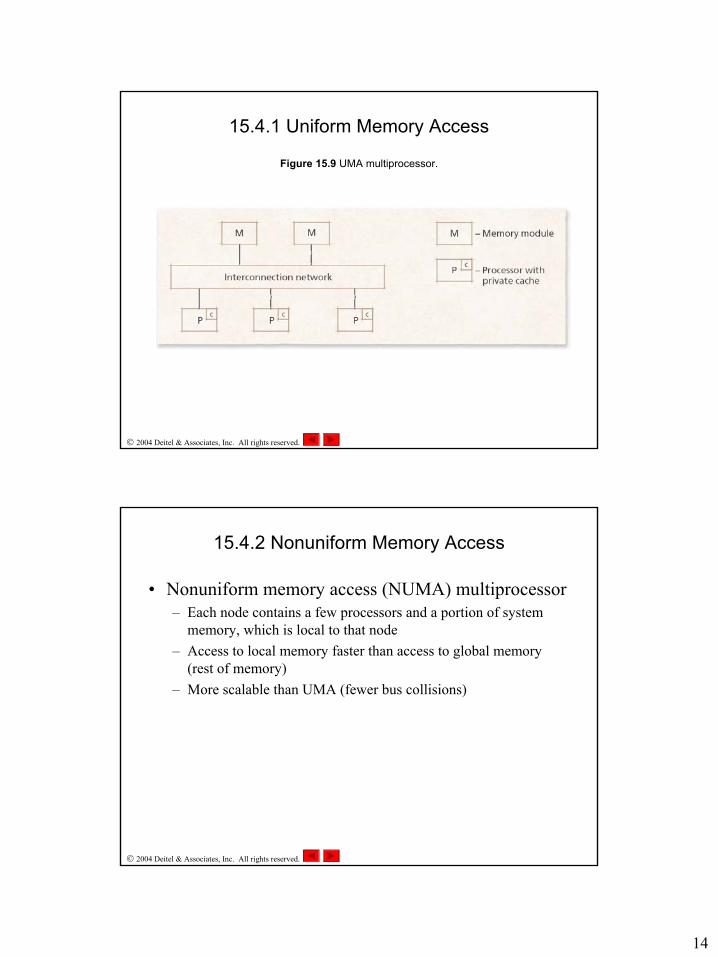
• Uniform memory access (UMA) multiprocessor– All processors share all memory– Access to any memory page is nearly the same for all processors
and all memory modules (disregarding cache hits)– Typically uses shared bus or crossbar-switch matrix– Also called symmetric multiprocessing (SMP)– Small multiprocessors (typically two to eight processors)
14
2004 Deitel & Associates, Inc. All rights reserved.
Figure 15.9 UMA multiprocessor.
15.4.1 Uniform Memory Access
2004 Deitel & Associates, Inc. All rights reserved.
15.4.2 Nonuniform Memory Access
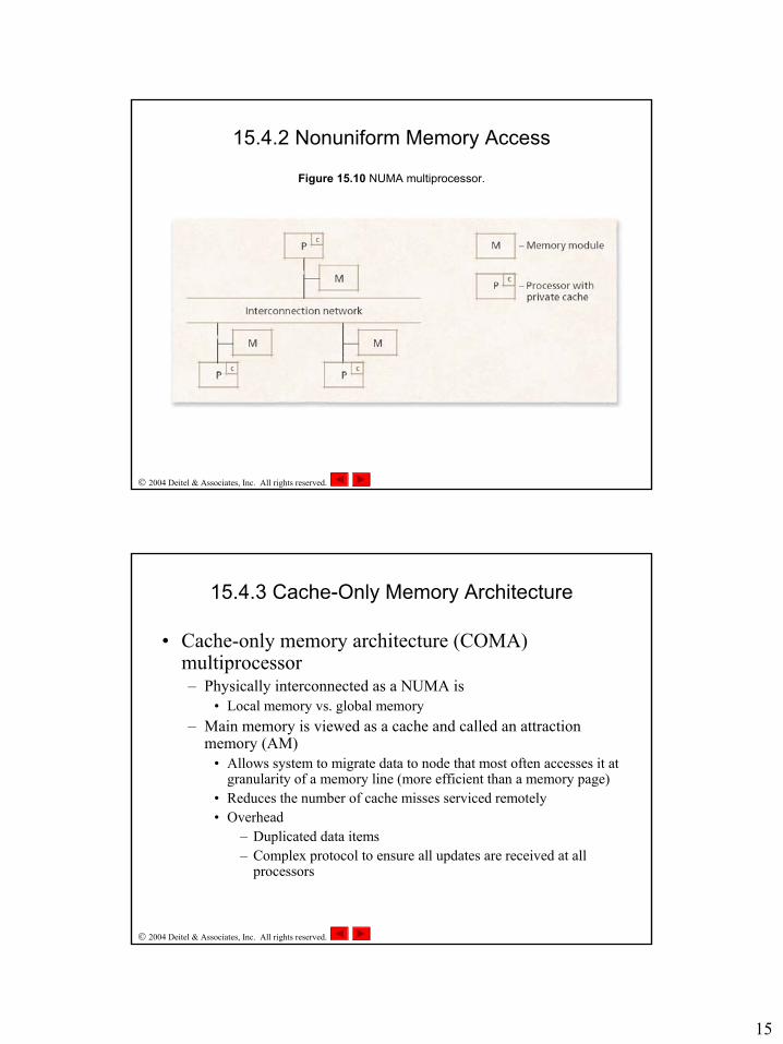
• Nonuniform memory access (NUMA) multiprocessor– Each node contains a few processors and a portion of system
memory, which is local to that node– Access to local memory faster than access to global memory
(rest of memory)– More scalable than UMA (fewer bus collisions)
15
2004 Deitel & Associates, Inc. All rights reserved.
Figure 15.10 NUMA multiprocessor.
15.4.2 Nonuniform Memory Access
2004 Deitel & Associates, Inc. All rights reserved.
15.4.3 Cache-Only Memory Architecture
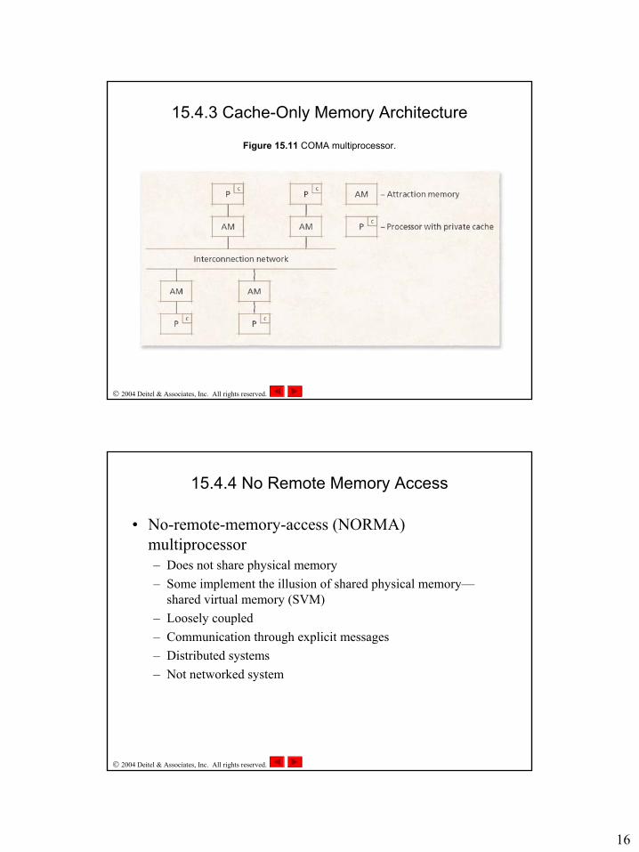
• Cache-only memory architecture (COMA) multiprocessor– Physically interconnected as a NUMA is
• Local memory vs. global memory– Main memory is viewed as a cache and called an attraction
memory (AM)• Allows system to migrate data to node that most often accesses it at
granularity of a memory line (more efficient than a memory page)• Reduces the number of cache misses serviced remotely• Overhead
– Duplicated data items– Complex protocol to ensure all updates are received at all
processors
16
2004 Deitel & Associates, Inc. All rights reserved.
Figure 15.11 COMA multiprocessor.
15.4.3 Cache-Only Memory Architecture
2004 Deitel & Associates, Inc. All rights reserved.
15.4.4 No Remote Memory Access
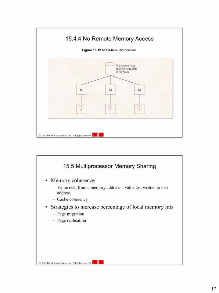
• No-remote-memory-access (NORMA) multiprocessor– Does not share physical memory– Some implement the illusion of shared physical memory—
shared virtual memory (SVM)– Loosely coupled– Communication through explicit messages– Distributed systems– Not networked system
17
2004 Deitel & Associates, Inc. All rights reserved.
Figure 15.12 NORMA multiprocessor.
15.4.4 No Remote Memory Access
2004 Deitel & Associates, Inc. All rights reserved.
15.5 Multiprocessor Memory Sharing
• Memory coherence– Value read from a memory address = value last written to that
address– Cache coherency
• Strategies to increase percentage of local memory hits– Page migration– Page replication
18
2004 Deitel & Associates, Inc. All rights reserved.
15.5.1 Cache Coherence
• UMA cache coherence– Bus snooping– Centralized directory– Only one processor can cache a data item
• CC-NUMA cache coherence– Small systems—use UMA protocols– Large systems—home-based coherence
• Each address is associated with a home node• Contact home node on reads and writes to receive most updated
version of data• Three network traversals per coherency operation
2004 Deitel & Associates, Inc. All rights reserved.
15.5.2 Page Replication and Migration
• Page replication– System places a copy of a memory page at a new node– Good for pages read by processes at different nodes, but not
written• Page migration
– System moves a memory page from one node to another– Good for pages written to by a single remote process
• Increases percentage of local memory hits• Drawbacks
– Memory overhead – duplicated pages, page access histories– Replicating and migrating more expensive than remotely
referencing so only useful if referenced again
19
2004 Deitel & Associates, Inc. All rights reserved.
15.5.3 Shared Virtual Memory
• Shared VM:– Illusion of shared physical memory– Coherency Protocols
• Invalidation• Write broadcast
– When to apply protocols• Sequential consistency• Relaxed consistency
– Release and lazy release consistency– Home-based consistency– Delayed consistency– Lazy data propagation
2004 Deitel & Associates, Inc. All rights reserved.
15.6 Multiprocessor Scheduling
• Determines the order and to which processors processes are dispatched
• Two goals– Parallelism – timesharing scheduling– Processor affinity – space-partitioning scheduling
• Soft affinity• Hard affinity
• Types of scheduling algorithms– Job-blind– Job-aware– Per-processor or per-node run queues

20
2004 Deitel & Associates, Inc. All rights reserved.
15.6.1 Job-Blind Multiprocessor Scheduling
• Job-blind MP scheduling– Global run queues– Straightforward extension of uniprocessor algorithms– Examples
• First-in-first out (FIFO) multiprocessor scheduling• Round-robin process (RRprocess) multiprocessor scheduling• Shortest process first (SPF) multiprocessor scheduling
2004 Deitel & Associates, Inc. All rights reserved.
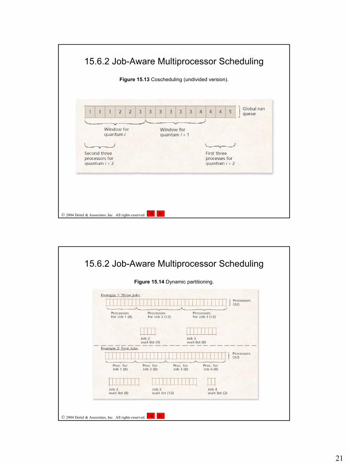
15.6.2 Job-Aware Multiprocessor Scheduling
• Job-aware MP scheduling– Global run queues– Algorithms that maximize parallelism
• Shortest-number-of-processes-first (SNPF) scheduling• Round-robin job (RRjob) scheduling• Coscheduling
– Processes from the same job placed in adjacent spots in the global run queue
– Sliding window moves down run queue running adjacent processes that fit into window (size = number of processors)
– Algorithms that maximize processor affinity• Dynamic partitioning
21
2004 Deitel & Associates, Inc. All rights reserved.
Figure 15.13 Coscheduling (undivided version).
15.6.2 Job-Aware Multiprocessor Scheduling
2004 Deitel & Associates, Inc. All rights reserved.
Figure 15.14 Dynamic partitioning.
15.6.2 Job-Aware Multiprocessor Scheduling
22
2004 Deitel & Associates, Inc. All rights reserved.
15.7 Process Migration
• Transferring a process from one node to another node• Benefits of process migration
– Increases fault tolerance– Load balancing– Reduces communication costs– Resource sharing
2004 Deitel & Associates, Inc. All rights reserved.
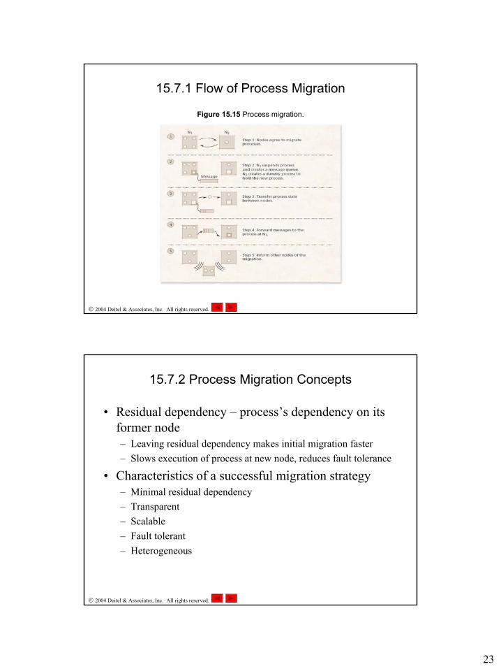
15.7.1 Flow of Process Migration
• Process’s state includes– Pages marked as valid in virtual memory– Register contents– State of opened files
• Flow of migration– Either sender or receiver initiates request– Sender suspends migrating process– Sender creates message queue for migrating process’s messages– Sender transmits state to a “dummy” process at the receiver– Sender and receiver notify other nodes of process’s new location– Sender deletes its instance of the process
23
2004 Deitel & Associates, Inc. All rights reserved.
Figure 15.15 Process migration.
15.7.1 Flow of Process Migration
2004 Deitel & Associates, Inc. All rights reserved.
15.7.2 Process Migration Concepts
• Residual dependency – process’s dependency on its former node– Leaving residual dependency makes initial migration faster– Slows execution of process at new node, reduces fault tolerance
• Characteristics of a successful migration strategy– Minimal residual dependency– Transparent– Scalable– Fault tolerant– Heterogeneous
24
2004 Deitel & Associates, Inc. All rights reserved.
15.7.3 Process Migration Strategies
• Eager migration– Transfer entire state during initial migration
• Dirty eager migration– Only transfer dirty memory pages– Clean pages brought in from secondary storage
• Copy-on reference migration– Similar to dirty eager except clean pages can also be acquired
from sending node
• Lazy copying– No memory transfer
2004 Deitel & Associates, Inc. All rights reserved.
15.7.3 Process Migration Strategies
• Flushing migration– Flush all dirty pages to disk before migration– Transfer no memory pages during initial migration
• Precopy migration– Begin transferring memory pages before suspending process– Migrate once dirty pages reach a lower threshold
25
2004 Deitel & Associates, Inc. All rights reserved.
15.8 Load Balancing
• Load balancing– System attempts to distribute the processing load evenly among
processors– Reduces variance in response times– Ensures no processors remain idle while other processors are
overloaded– Two types
• Static load balancing• Dynamic load balancing
2004 Deitel & Associates, Inc. All rights reserved.
15.8.1 Static Load Balancing
• Static load balancing:– Useful in environments in which jobs exhibit predictable
patterns– Goals
• Distribute the load• Reduce communication costs
– Solve using a graph– Must use approximations for large systems to balance loads with
reasonable overhead
26
2004 Deitel & Associates, Inc. All rights reserved.
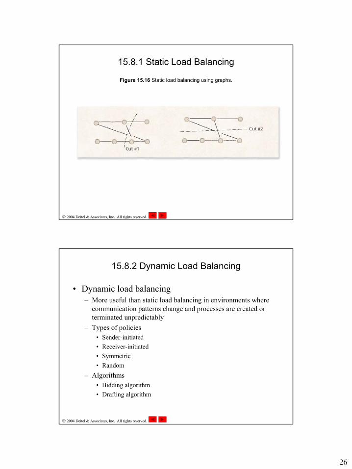
Figure 15.16 Static load balancing using graphs.
15.8.1 Static Load Balancing
2004 Deitel & Associates, Inc. All rights reserved.
15.8.2 Dynamic Load Balancing
• Dynamic load balancing– More useful than static load balancing in environments where
communication patterns change and processes are created or terminated unpredictably
– Types of policies• Sender-initiated• Receiver-initiated• Symmetric• Random
– Algorithms• Bidding algorithm• Drafting algorithm
27
2004 Deitel & Associates, Inc. All rights reserved.
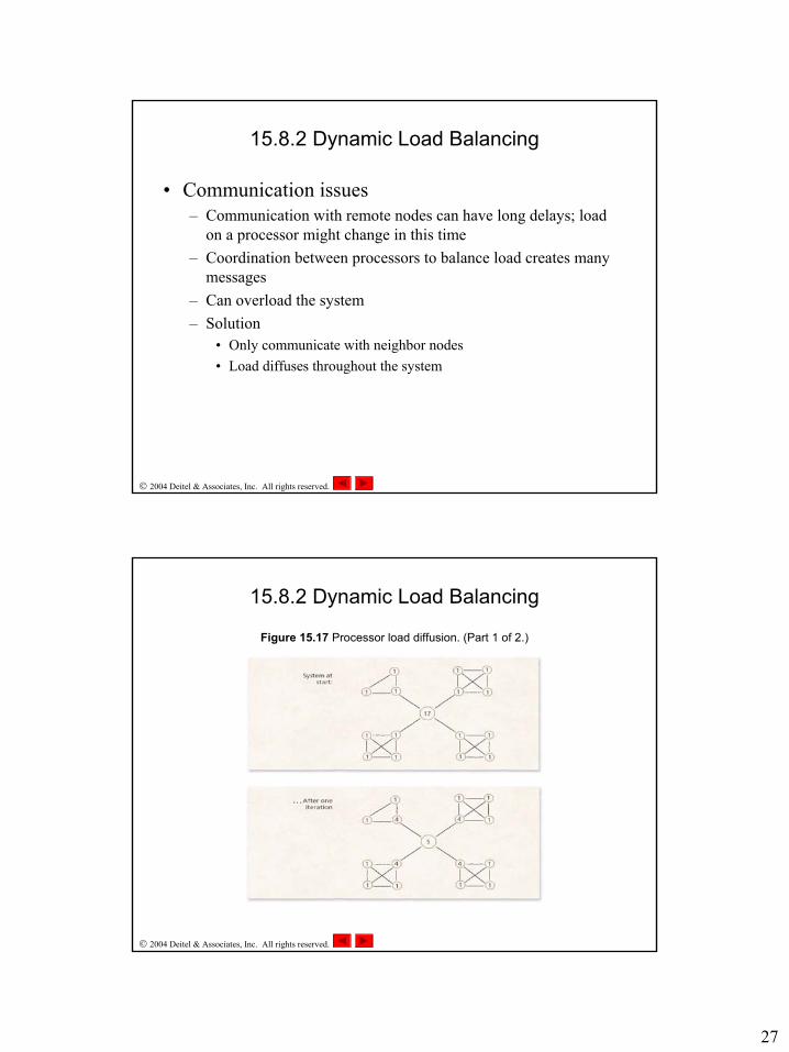
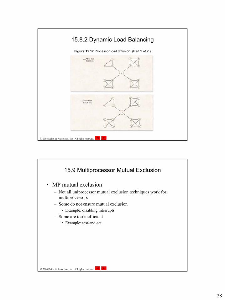
15.8.2 Dynamic Load Balancing
• Communication issues– Communication with remote nodes can have long delays; load
on a processor might change in this time– Coordination between processors to balance load creates many
messages– Can overload the system– Solution
• Only communicate with neighbor nodes• Load diffuses throughout the system
2004 Deitel & Associates, Inc. All rights reserved.
Figure 15.17 Processor load diffusion. (Part 1 of 2.)
15.8.2 Dynamic Load Balancing
28
2004 Deitel & Associates, Inc. All rights reserved.
Figure 15.17 Processor load diffusion. (Part 2 of 2.)
15.8.2 Dynamic Load Balancing
2004 Deitel & Associates, Inc. All rights reserved.
15.9 Multiprocessor Mutual Exclusion
• MP mutual exclusion– Not all uniprocessor mutual exclusion techniques work for
multiprocessors– Some do not ensure mutual exclusion
• Example: disabling interrupts– Some are too inefficient
• Example: test-and-set
29
2004 Deitel & Associates, Inc. All rights reserved.
15.9.1 Spin Locks
• Spin lock: waiting processes busy-wait for lock– Wastes processor cycles– Ensures quick response to lock release (reduces context
switches)
• Delayed blocking: spin for a short time, then block
2004 Deitel & Associates, Inc. All rights reserved.
15.9.1 Spin Locks
• Advisable process lock (APL) – Lock holder specifies time it will hold the lock– Waiting processes can decide whether to block or spin
• Adaptive (or configurable) locks: lock holder can change the type of lock– Spin locks when system load is low– Blocking locks when system load is high
30
2004 Deitel & Associates, Inc. All rights reserved.
15.9.2 Sleep/Wakeup Locks
• Sleep/wakeup lock– Processes waiting for the lock sleep– Upon release, lock holder wakes next process, which obtains the
lock– Eliminates several problems with blocking locks in
multiprocessors• Race condition• Thundering herd
2004 Deitel & Associates, Inc. All rights reserved.
15.9.3 Read/Write Locks
• Read/write lock– Multiple processes (readers) can hold the lock in shared mode– One process (writer) can hold the lock in exclusive mode– Can be used to solve the readers-and-writers problem