chapter 15 flapless crestal sinus augmentation: … in the flapless crestal sinus augmentation...
TRANSCRIPT
C15 12/30/2015 11:13:50 Page 152
CHAPTER 15
Flapless Crestal Sinus Augmentation: HydraulicTechnique
Byung-Ho Choi
Department of Oral and Maxillofacial Surgery, Yonsei University Wonju College of Medicine, Wonju, South Korea
IntroductionThe optimization of maxillary sinus floor elevation protocols toachieve high implant success rates, minimize morbidity, shortentreatment periods, and allow for simultaneous implant placement isa constant challenge for clinicians. The author describes a flaplesscrestal sinus floor augmentation procedure using a hydraulic sinuselevation system. The minimally invasive flapless procedure signifi-cantly decreases post-operative discomfort and complications ver-sus conventional open-flap surgery [1, 2]. In flapless crestal sinusaugmentation surgery, both transcrestal osteotomy and sinus mem-brane elevation are performed via the implant osteotomy sitewithout visual or tactile control [3]. For this reason, computer-guided surgery is mandatory, not just to guide drilling for implantplacement but also to control the drill depth to the bony sinus floorwhen entering the bony sinus floor [4, 5]. To achieve high successrates in the flapless crestal sinus augmentation procedure, mem-brane integrity is a primary condition for success. In order to safelymaintain membrane integrity, it is necessary to improve the tech-niques and instruments. This chapter addresses the techniques andinstruments for successful flapless crestal sinus floor augmentation,using a hydraulic sinus elevation system combined with computer-guided implant surgery.
Surgical instruments1 Osteotomy drill2 Dome-shaped crestal approach bur3 Hydraulic membrane lifter4 Bone plugger, sinus curette5 Stopper6 Digital surgical guide
1. Osteotomy drillThis drill is used to drill to 1mm short of the sinus floor. It comeswith various lengths and diameters with a stop feature. The surgicalguide guides the drill’s depth, direction, and position.
2. Dome-shaped crestal approach burThis bur is used to eliminate the remaining bone below the sinusfloor (Figure 15.1). The bur has a round tip and vertical stop. The tip
of the drill is characterized by a smooth cutting blade. This shapehelps to avoid direct damage even if it comes in direct contact withthe sinus membrane. The dome shape also makes it safe to use ineither flat or steep bone walls. The bur also has a stop feature tocontrol the drill depth through the surgical guide. To help controlthe drill depth precisely, a number of different stopper lengths areavailable. Using the stop feature and the stoppers, the drill depth canbe controlled within a 1mm range. The dome-shaped crestalapproach bur has a 3.2mm diameter, which is smaller than thediameter of implants placed in the maxillary premolar (Ø4.0mm)and molar (Ø5.0mm).
3. Hydraulic membrane lifterThis is for injecting liquid into the maxillary sinus. It is comprised ofa syringe, tube, and a nozzle (Figure 15.2). The tip of the nozzle has afeature that can completely close the opening to the drill hole. Thus,it has a conical-shaped sealing part and an extension part that isinserted into the drill hole. The other end of the nozzle is connectedwith the tube, which is then connected to a saline-filled syringe. Thenozzle also has a handle feature (Figure 15.3). The handle not onlyhelps the nozzle to be positioned into the hole and secured in placebut it also helps the nozzle to pressurize the opening area. Thesyringe should be a 5ml disposable syringe. A 1ml syringe is toosmall to apply sufficient pressure. In addition, if the extension partof the syringe that connects the tube to the syringe is too short, thetube can be easily separated when applying pressure. Therefore, ifpossible, use a syringe with an elongated connection part.
4. Bone plugger, sinus curetteA bone plugger is used to insert the bone-grafting material into thesinus cavity through the drill hole. A sinus curette is then used todisperse this bone-grating material in the sinus cavity (Figure 15.4).They have a stop feature to control the depth of insertion into thesinus cavity. Their diameters are Ø2.6mm, which will allow entryinto the Ø3.2mm hole created by the 3.2mm diameter, dome-shaped crestal approach bur. The head of the sinus curette has adome shape.
5. StopperThe stopper is designed to be able to connect to the crestal approachbur, bone plugger, or sinus curette. It also comes in varying lengths,
152
Vertical Alveolar Ridge Augmentation in Implant Dentistry: A Surgical Manual, First Edition. Edited by Len Tolstunov.© 2016 John Wiley & Sons, Inc. Published 2016 by John Wiley & Sons, Inc.

C15 12/30/2015 11:13:50 Page 153
which can help control the depth of insertion into the sinus cavitywithin a 1mm range (Figure 15.5).
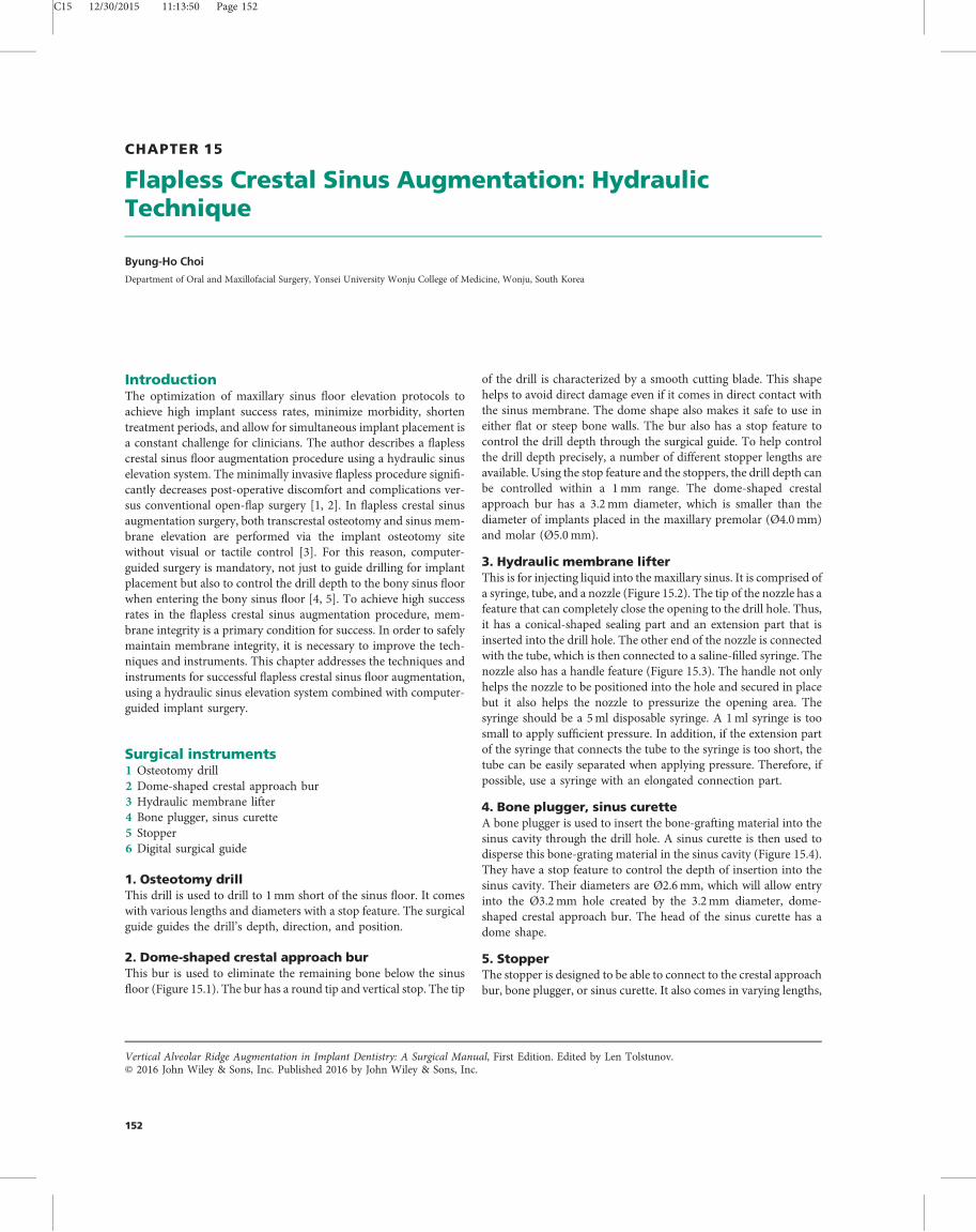
6. Digital surgical guideThe surgical guide guides the depth and direction of the osteotomydrill, crestal approach bur, and the implant. Therefore, a highlyaccurate and precise surgical guide must be used – the recom-mended vertical error value should be less than 0.5mm. From theauthor’s experiments, an average vertical error value of 0.44mmwas achieved if the surgical guide was digitally designed using boththe cone beam computed tomography (CBCT) image and the oral
scan image taken by TRIOS (3Shape, Copenhagen, Denmark) andproduced using a 3D printer. The error from the digital surgicalguide might have resulted from each step of the surgical guideproduction, including the digital impression step, the fusion of thesurface scan image with the CBCT scan image, and the 3D printingprocess. The error value increases if the surgical guide is made withthe use of stone models from alginate impressions instead of digitalimpressions. If the vertical error value of the surgical guide is greaterthan 1mm, the risk of membrane perforation increases.
Technique
Pre-operative protocolThe best location to penetrate the bony sinus floor is determinedwith the help of CBCT images of the maxillary sinus while takinginto consideration both the position of the final prosthesis and theanatomy of the maxillary sinus, such as the shapes of the sinus wallsas well as the presence of the septum. This location will be where theimplant is placed. Once the location has been determined, thedrilling depth is calculated. This is important so as to avoid causingmembrane perforation while drilling. Cross-sectional CBCT imagescan help define the length of the osteotomy up to the sinus floor. Apanoramic 2D image or dental X-rays are not appropriate for thispurpose as they are not precise enough. In contrast, a CBCT imagecan show the anatomy of the maxillary sinus with great precision inthree dimensions. CBCT scans and oral digital impressions are usedto perform three-dimensional implant planning and to create a
Figure 15.1 Dome-shaped crestal approach burs.
Figure 15.2 Hydraulic membrane lifter.
Figure 15.4 Bone plugger and sinus curette.
Figure 15.3 Nozzle with handle.
Figure 15.5 Stoppers.
Flapless Crestal Sinus Augmentation: Hydraulic Technique 153
C15 12/30/2015 11:13:51 Page 154
customized surgical guide (Figure 15.6). If immediate restoration isbeing performed, the customized abutment and provisional resto-ration is designed and then made using the computer-aided design/computer-aided manufacturing (CAD/CAM) milling machine.When designing the customized abutment and crown, one mustconsider factors such as the soft tissue profile around the proposedlocation of the implant and the relationship between the implantwith its adjacent and opposite teeth using dental design software(Dental System, 3Shape, Copenhagen, Denmark). The surgicalguide, prefabricated customized abutment and crown are preparedbefore implant surgery.
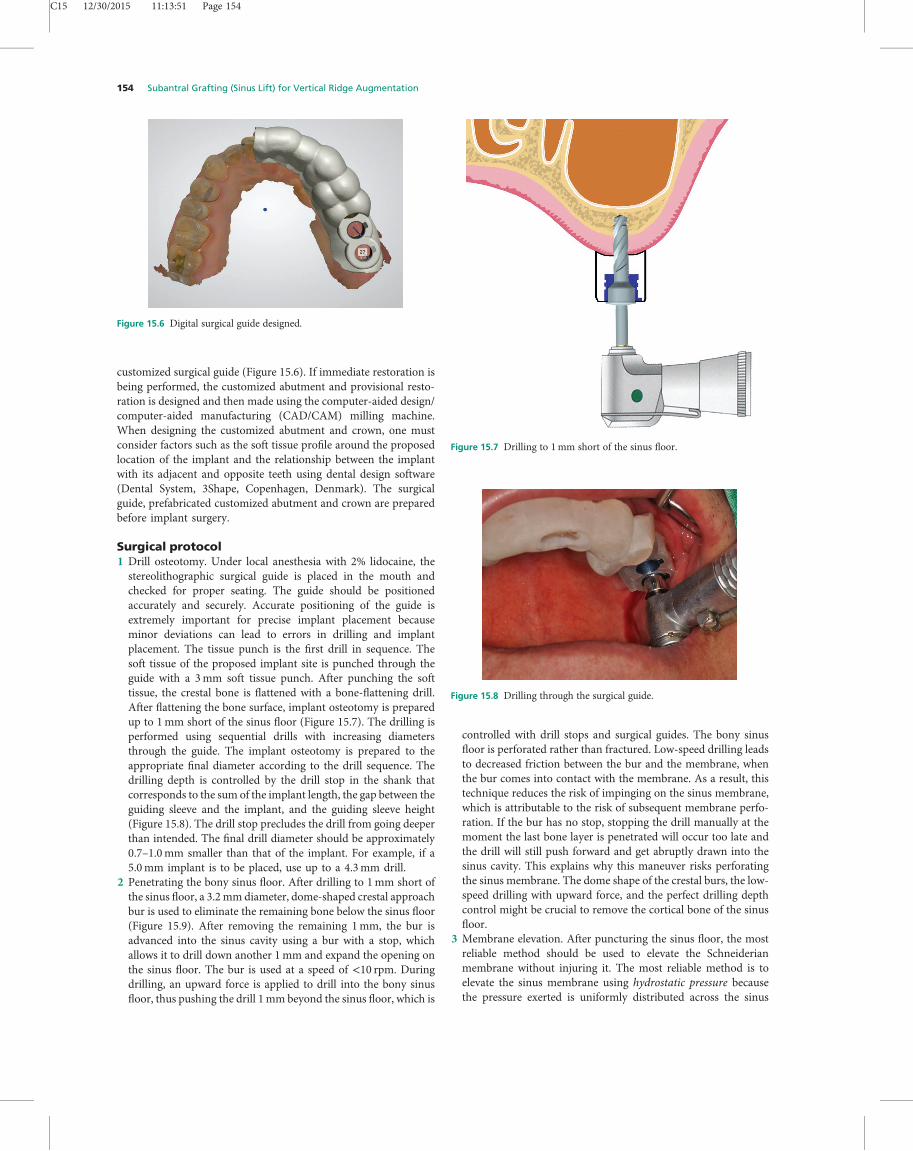
Surgical protocol1 Drill osteotomy. Under local anesthesia with 2% lidocaine, thestereolithographic surgical guide is placed in the mouth andchecked for proper seating. The guide should be positionedaccurately and securely. Accurate positioning of the guide isextremely important for precise implant placement becauseminor deviations can lead to errors in drilling and implantplacement. The tissue punch is the first drill in sequence. Thesoft tissue of the proposed implant site is punched through theguide with a 3mm soft tissue punch. After punching the softtissue, the crestal bone is flattened with a bone-flattening drill.After flattening the bone surface, implant osteotomy is preparedup to 1mm short of the sinus floor (Figure 15.7). The drilling isperformed using sequential drills with increasing diametersthrough the guide. The implant osteotomy is prepared to theappropriate final diameter according to the drill sequence. Thedrilling depth is controlled by the drill stop in the shank thatcorresponds to the sum of the implant length, the gap between theguiding sleeve and the implant, and the guiding sleeve height(Figure 15.8). The drill stop precludes the drill from going deeperthan intended. The final drill diameter should be approximately0.7–1.0mm smaller than that of the implant. For example, if a5.0mm implant is to be placed, use up to a 4.3mm drill.
2 Penetrating the bony sinus floor. After drilling to 1mm short ofthe sinus floor, a 3.2mmdiameter, dome-shaped crestal approachbur is used to eliminate the remaining bone below the sinus floor(Figure 15.9). After removing the remaining 1mm, the bur isadvanced into the sinus cavity using a bur with a stop, whichallows it to drill down another 1mm and expand the opening onthe sinus floor. The bur is used at a speed of <10 rpm. Duringdrilling, an upward force is applied to drill into the bony sinusfloor, thus pushing the drill 1mm beyond the sinus floor, which is
controlled with drill stops and surgical guides. The bony sinusfloor is perforated rather than fractured. Low-speed drilling leadsto decreased friction between the bur and the membrane, whenthe bur comes into contact with the membrane. As a result, thistechnique reduces the risk of impinging on the sinus membrane,which is attributable to the risk of subsequent membrane perfo-ration. If the bur has no stop, stopping the drill manually at themoment the last bone layer is penetrated will occur too late andthe drill will still push forward and get abruptly drawn into thesinus cavity. This explains why this maneuver risks perforatingthe sinus membrane. The dome shape of the crestal burs, the low-speed drilling with upward force, and the perfect drilling depthcontrol might be crucial to remove the cortical bone of the sinusfloor.
3 Membrane elevation. After puncturing the sinus floor, the mostreliable method should be used to elevate the Schneiderianmembrane without injuring it. The most reliable method is toelevate the sinus membrane using hydrostatic pressure becausethe pressure exerted is uniformly distributed across the sinus
Figure 15.8 Drilling through the surgical guide.
Figure 15.6 Digital surgical guide designed.
Figure 15.7 Drilling to 1mm short of the sinus floor.
154 Subantral Grafting (Sinus Lift) for Vertical Ridge Augmentation

C15 12/30/2015 11:13:52 Page 155
membrane to minimize membrane tearing during membraneelevation [6, 7]. Compared to other techniques, the hydraulicpressure generated by injecting saline into the drill hole offers themost uniform distribution of forces, resulting in uniform ele-vation of the sinus membrane [8]. This is supported by finiteelement analyses conducted by Pommer et al., which confirmedthat the pressure was uniformly distributed across the elevatedmembrane [9].
Membrane elevation is completed without the surgical guide.First, the hydraulic membrane lifter’s nozzle is connected with thehandle, and then the nozzle is positioned in the opening of thedrill hole and secured in place. Next, 0.8ml of saline is slowlyinjected to separate the sinus membrane from the bony sinusfloor and to push the membrane upward (Figure 15.10). Approx-imately the first 0.3–0.4ml will go into the drill hole withoutfeeling pressure. As the saline enters the hole and touches thesinus membrane, the membrane is elevated with feeling pressure;however, as soon as the membrane is elevated, the pressure isdecreased. It is important not to inject too much saline as the
pressure decreases as this can elevate the sinus membrane toomuch. Therefore, saline should be slowly injected 0.1ml at a time(Figure 15.11). If the sinus floor has not been fully penetrated, thepressure can be felt after injecting 0.3–0.4ml of saline but nomore saline can be injected, in which case another attempt shouldbe made to reinject saline after drilling an additional 1mm intothe sinus cavity using the 3.2mm diameter, dome-shaped crestalapproach bur.
4 Membrane integrity test. The most reliable way to test membraneintegrity is the aspiration technique. The membrane integrity isevaluated by drawing the saline back through the drill hole.The volume of saline that was injected is fully retrieved, suggest-ing that the membrane remains intact. Directly viewing thesinus membrane, using the Valsalva maneuver (light forcefulattempted exhalation against a close nasal airway, for example),and probing or irrigation does not guarantee preservation of thesinus membrane. In the author’s view, retrieving and measuringthe injected saline back through the drill hole is the best test toguarantee membrane integrity.
Sinus membrane perforation is tested immediately after ele-vating the sinus membrane. Once 0.8ml of saline is injected toelevate the sinus membrane, the same syringe is used to withdrawthe saline. If all the saline that was just injected is withdrawn backup and the syringe shows negative pressure, then the membranehas not been perforated. There will be some blood and bubblesthat get aspirated with the saline because the air that was in thehole can be pushed in with the saline and some bleeding canoccur as the membrane is separated from the bone. The sinusmembrane is perforated if only part of the saline is sucked backup and the syringe is unable to achieve negative air pressure. Ifthis is the case, do not place bone-grafting material into the sinuscavity. It is possible that mucus can penetrate the graft throughthe perforation site and negatively affect bone formation aftersurgery. In addition, bone graft material can escape into the sinuscavity through the perforated area causing sinus inflammation.
Figure 15.10 Nozzle positioned into the transcrestal osteotomy canal andsecured in place.
Figure 15.11 Saline injected to separate the sinus membrane from thebony sinus floor.
Figure 15.9 Dome-shaped crestal approach drill eliminating the remainingbone below the sinus floor.
Flapless Crestal Sinus Augmentation: Hydraulic Technique 155

C15 12/30/2015 11:13:52 Page 156
If the membrane is perforated during the membrane elevationprocedure, the surgery should be reattempted after about twomonths. During the reattempt, the surgery is tried from adifferent area, away from the sinus membrane that was damagedin order to improve the success rate.
5 Expanding the opening hole of the sinus floor. Prior to insertingthe grafting material into the maxillary sinus, the opening hole ofthe sinus floor into the sinus cavity is expanded. The surgicalguide is replaced in the mouth and using the 3.2mm diameter,dome-shaped crestal approach bur, the hole is expanded byadvancing it an additional 1mm into the sinus cavity (Figure15.12). The bur should be advanced precisely 1mm into the sinuscavity using the surgical guide and stop on the bur. After that, thesurgical guide is removed and the bone plugger is inserted tocheck for the presence of any other bony barriers inside the hole –ensuring that the opening is completely clear. The bone pluggershould be restricted to not insert into the sinus cavity further thanthe additional 1mm using a stopper.
6 Grafting procedure. The bone grafting procedure is performedwithout the aid of a surgical guide. If a Bio-Oss collagen sponge(Geistlich Pharma AG, Wolhusen, Switzerland) is used as thegraft material, a 1 cm3 portion of the sponge is cut into nine piecesand then inserted into the sinus cavity through the drill hole usingthe bone plugger.When inserted into the sinus cavity, the graftingmaterial has a tendency to remain pushed upwards. Therefore, itis necessary to spread the material in the sinus cavity. Wheneverapproximately 0.2–0.3ml of grafting material is inserted, it isdispersed using a sinus curette by rotating the sinus curette in thesinus cavity, both clockwise and counterclockwise, drawing thelargest circle possible (Figure 15.13). The amount of graftingmaterial inserted is determined by the height of membraneelevation. When attempting to elevate the membrane by3mm, insert 0.3ml; to elevate by 5mm, insert 0.5ml; to elevateby 7mm, insert 0.7ml. If only the grafting material is insertedinto the sinus cavity without placing implants, an additional0.3ml is inserted. For example, when attempting to elevate by7mm, 1ml of graft material is inserted.
7 Implant placement. Simultaneous implant placement is con-ducted. Before implant placement, final drilling is performed1mm beyond the sinus floor through the surgical guide to enlargethe sinus floor. Implants are then placed in the formed socketthrough the guide. It is recommended that implants be placedsimultaneously with the grafting procedure because the implantwill help disperse the grafting material as well as help keep themembrane elevated. However, if the vertical height of the residualbone is less than 2mm and the implant has no primary stability,only the bone-grafting material is inserted into the sinus cavitywithout placing implants. Implant stability is evaluated by resist-ance of the implant during insertion and via measurement of theimplant’s insertion torque.
8 Immediate restoration or installing a healing abutment. Imme-diate restoration is performed using the customized abutmentand preliminary restoration that was prefabricated pre-surgery ifthe following conditions have been met: for a single implant,immediate restoration is performed if the primary stability isgreater than 30N cm. For the implant that is splinted withneighboring implants, immediate restoration is performed ifthe primary stability is greater than 20N cm. The restorationprocess must follow the immediate non-functional loading con-cept by adjusting the crown to avoid contact with the opposingteeth Figure 15.14. Patients are asked to refrain from using the
Figure 15.14 Immediate restoration with prefabricated resin temporarycrowns. The occlusion and articulation of the crowns were adjusted out ofcontact with the opposing teeth.
Figure 15.12 Dome-shaped crestal approach drill pushed 1mm beyondthe sinus floor.
Figure 15.13 Sinus curette used to spread the graft material.
156 Subantral Grafting (Sinus Lift) for Vertical Ridge Augmentation

C15 12/30/2015 11:13:53 Page 157
restored teeth for 3–4 months. A cover screw or healing abutmentis installed if the implant is unable to secure the primarystabilization.
9 Radiographic evaluation. Patients are scanned post-operativelywith the CBCT unit to inspect and identify any sinus membraneperforations (Figure 15.15).
AdvantagesCompared to a lateral approach, the flapless crestal approach offersmany advantages. Pain, discomfort, and healing time are greatlyreduced because of the absence of trauma resulting from the largesinus floor incisions that are used in lateral sinus elevation surger-ies [10–13]. The flapless crestal approach preserves the integrity ofthe bony sinus structure, except at the implant site. In addition, thisis a flapless procedure, which is the result of using punch incisionsand simultaneous implant placement with the transmucosal com-ponents. The flapless crestal approach eliminates the need for asecond surgical procedure to connect the transmucosal compo-nents, thereby reducing chair time [6, 14]. The esthetic results arealso improved compared to the lateral approach [10]. Based on theauthor’s experience, the average operative time for the flaplesscrestal approach was 17± 15 minutes. The surgical proceduresubstantially decreased the length of surgery compared to theprevious crestal approaches. Some possible reasons for this short-ened operative time might be due to using drills with stops, usingsurgical guides, the effective membrane elevation system, eliminat-ing the need for sutures, and avoiding soft tissue elevation. Inaddition to a shorter operative time, the approach is successful inanatomically difficult sinus structures. During sinus lift surgery,
problems are not encountered in the presence of antral septa orwhen drilling along a steep bone wall. Therefore, this procedure canbe highly successful in patients with septated maxillary sinuses.
In patients with antral septumThe presence of an antral septum in the sinus cavity poses addi-tional difficulties for a lateral approach. As a result, the lateralapproach requires greater skill of the surgeon and longer operativetime. Even surgeons with a lot of experience often cause sinusmembrane perforation; however, with the aid of a surgical guide andhydraulic pressure, the flapless crestal approach makes the proce-dure simpler and faster (Figure 15.16a to c). The septum canactually be utilized to aid in shaping the grafting material in themaxillary sinus (Figure 15.17a and b). One of the reasons for thehigh success rate in patients with septated maxillary sinuses is thatthe dome-shaped crestal approach bur, which is used to drillthrough the sinus floor, can be safely used in steep bone walls aswell (Figure 15.18). Due to its round shape, the drill works whetherthe surface is flat or not. Bone in the septum area tends to be hard,which can help implants achieve primary stability. If the pre-surgeryCBCT scan reveals the presence of a septum, the surgeon must takethis into consideration in determining the appropriate position anddepth of initial drilling. When drilling through a steep sinus wall,depending on the angle, the surgeon may need to drill an additional1mm compared to when drilling through a flat wall.
In patients with severely atrophic maxillaeEven in patients with severely atrophic maxillae (1 to 2mm ofresidual bone), the implants can be successfully inserted at the sametime as maxillary sinus elevation (Figure 15.19a and b) [15].Typically in these situations, the maxillary sinus floor wall hashardened the cortical bone remaining. To successfully placeimplants in 1 to 2mm of bone in the posterior maxilla, the residualbone quality should be effectively used to achieve primary implantstability. The drilling and implant placement is performed withoutshaking the axis with the aid of a surgical guide. Tapered implantsare used. The osteotomy for implant placement is enlarged to0.7–1.0mm narrower than the anticipated implant diameter.
Grafting materialIt is difficult to create a desirable shape of the grafting material in thesinus cavity through the flapless crestal approach because thematerial is inserted without the ability to see inside the sinus cavity.The goal of the grafting procedure using the flapless crestalapproach is to simply maintain the space created by the sinus
Figure 15.16 A case with antral septa: (a) before, (b) immediately, and (c) 6 months after surgery.
Figure 15.15 CBCT scan taken immediately after surgery.
Flapless Crestal Sinus Augmentation: Hydraulic Technique 157

C15 12/30/2015 11:13:54 Page 158
membrane elevation. In other words, the goal is to keep the sinusmembrane elevated to encourage new bone formation underneaththe membrane. The elevated sinus membrane can act like a tentwhile enabling blood flow and taking advantage of the bone’sregeneration ability. The environment of the sinus cavity below
the lifted sinus membrane after sinus membrane elevation is quitebeneficial for bone formation [16, 17]. This is in part because thecavity is surrounded by bone and the primary source ofrevascularization of the graft originates from the adjacent bonywalls. In addition, the sinus membrane has an intensely vascularnetwork and contains mesenchymal progenitor cells committed tothe osteogenic lineage [18]. The periosteum of the lifted sinusmembrane is another source of bone-forming cells. Accordingly,new bone formation in the newly created space can be induced byonly elevating the sinus membrane, provided that the space is wellmaintained. When the implant is placed along with grating mate-rial, both the implant and the graft material can help maintain theelevated sinus membrane. The graft material for the flapless crestalapproach must be selected on the basis of its ability to maintainspace, its ability to be inserted through a small opening, and its easeof dispersion inside the sinus cavity.The graft material can be in particle, gel, or sponge form. The
particle type can be pushed into the sinus cavity through the drillhole using a bone carrier; however, this type can be ineffective andmore time-consuming as the small opening makes it difficult for theparticles to be pushed in. The advantage of the gel type is that it canbe injected into the sinus cavity through the drill hole using asyringe; however, its disadvantage is that if there is space inside thesinus cavity, the gel can shift around. In particular, in a laid-downposition, the gel moves towards the back. If a thermosensitive gel isused instead, the gel may be able to solidify inside the sinus cavityand hold its shape. If the gel and particle types are mixed together,
Figure 15.19 Cone beam computed tomography (CBCT) scans of the severely atrophic ridge with 1mm of residual bone (a) before and (b) after surgery.
Figure 15.17 A case with antral septa: (a) before and (b) 6 months after surgery.
Figure 15.18 Dome-shaped crestal approach bur under the septum.
158 Subantral Grafting (Sinus Lift) for Vertical Ridge Augmentation

C15 12/30/2015 11:13:55 Page 159
two things can happen. First, if the ratio of the particle type isgreater than the gel type, the mixture might not be able to beinjected using a syringe. Second, if the ratio of the particle type is lessthan the gel type, the mixture may be absorbed too easily. Incontrast, if the sponge type material is inserted into the sinus cavityas a grafting material, the sponge can protect the membrane fromthe roughness of the graft material and may minimize membranetearing during the grafting procedure. The sponge type material issoft and more elastic, which makes it easier to handle. It can be cutinto a size that can easily be pushed through the hole and, whenpositioned, the sponge is able to maintain its space under theelevated sinus membrane. The Bio-Oss collagen sponge (GeistlichPharma AG, Wolhusen, Switzerland) is a commonly used sponge-type grafting material. The Bio-Oss collagen sponge is made up of90% calf cancellous bone and 10% pig collagen. Collagen spongemay not be suitable for maintaining the space because it can beabsorbed quickly; however, the Bio-Oss collagen sponge is suitablebecause Bio-Oss bone particles are able to maintain their shapewithout being absorbed too quickly when inside the sinus cavity(Figure 15.20a to c). The author’s animal experiment showed thatwhen the Bio-Oss collagen sponge was used as the graft material forbone augmentation in the maxillary sinus, bone formation in thegraft site was excellent and the mean osseointegration rate was morethan 40% (Figure 15.21a and b).
ConclusionThe first key factor for the success of flapless crestal sinus augmen-tation is penetrating the bony sinus floor using the dome-shapedcrestal approach bur, a low-speed drilling with upward force and a
perfect drilling depth control. The second factor is that hydraulicpressure is used to safely elevate the sinus membrane and check formembrane integrity. The third factor is that a CBCT scan with highresolution, advanced surgical equipment, and a highly precisesurgical guide are used for the surgery.
References1 Bassi MA, LopezMA: Hydraulica sinus lift: a newmethod proposal. J Osteol Biomat
2010;1:93–101.2 Engelke W, Capobianco M: Flapless sinus floor augmentation using endoscopy
combined with CT scan-designed surgical templates: method and report of 6consecutive cases. Int J Oral Maxillofac Implants 2005;20:891–897.
3 Toffler M: Minimally invasive sinus floor elevation procedures for simultaneousand staged implant placement. N Y State Dent J 2004;70:38–44.
4 Cassetta M, Stefanelli LV, Giansanti M, Calasso S: Accuracy of implant placementwith a stereolithographic surgical template. Int J Oral Maxillofac Implants2012;27:655–663.
5 D’haese J, Van De Velde T, Komiyama A, Hultin M, De Bruyn H: Accuracy andcomplications using computer-designed stereolithographic surgical guides for oralrehabilitation by means of dental implants: a review of the literature. Clin ImplantDent Relat Res 2012;14:321–335.
6 Chen I, Cha J: An 8-year retrospective study: 1,100 patients receiving 1,557implants using the minimally invasive hydraulic sinus condensing technique. JPeriodontol 2005;76:482–491.
7 Kao DW, DeHaven HA: Controlled hydrostatic sinus elevation: a novel method ofelevating the sinus membrane. Implant Dent 2011;20:425–429.
8 Watzek G. The Percrestal Sinus Lift – From Illusion to Reality. QuintessencePublishing, London, 2012, pp. 67–86.
9 Pommer B, Unger E, Sütö D, Hack N, Watzek G: Mechanical properties of theSchneiderian membrane in vitro. Clin Oral Implants Res 2009;20:633–637.
10 Fortin T, Bosson JL, Isidori M, Blanchet E: Effect of flapless surgery on painexperienced in implant placement using an image-guided system. Int J OralMaxillofac Implants 2006;21:298–304.
Figure 15.21 View of the specimen of Bio-Oss collagen sponge: (a) low ratio and (b) high ratio.
Figure 15.20 CBCT scans taken (a) before, (b) immediately, and (c) six months after surgery.
Flapless Crestal Sinus Augmentation: Hydraulic Technique 159

C15 12/30/2015 11:13:55 Page 160
11 Nkenke E, Eitner S, Radespiel-Troeger M, Vairaktaris E, Neukam FW, Fenner M:Patient-centred outcomes comparing transmucosal implant placement with anopen approach in the maxilla: a prospective, non-randomized pilot study. Clin OralImplants Res 2007;18:197–203.
12 Bensaha T: Outcomes of flapless crestal maxillary sinus elevation under hydraulicpressure. Int J Oral Maxillofac Implants 2012;27:1223–1229.
13 Brodala N: Flapless surgery and its effect on dental implant outcomes. Int J OralMaxillofac Implants 2009;24:118–125.
14 Kfir E, Goldstein M, Yerushalmi I: Minimally invasive antral membrane balloonelevation: results of a multicenter registry. Clin Implant Dent Relat Res 2009;11:e83–91.
15 PelegM,Mazor Z,ChaushuG,GargAK: Sinusfloor augmentationwith simultaneousimplant placement in the severely atrophic maxilla. Periodontol 1998;69:1397–1403.
16 Lundgren S, Andersson S, Gualini F, Sennerby L: Bone reformation with sinusmembrane elevation: a new surgical technique for maxillary sinus floor augmen-tation. Clin Implant Dent Relat Res 2004;6:165–173.
17 Palma VC, Magro-Filho O, Oliveira JA, Lundgren S, Salata LA, Sennerby L. Bonereformation and implant integration following maxillary sinus membrane eleva-tion: an experimental study in primates. Clin Implant Dent Relat Res 2006;8:11–24.
18 Gruber R, Kandler B, Fürst G, Fischer MB, Watzek G: Porcine sinus mucosa holdscells that respond to bone morphogenetic protein BMP-6 and BMP-7 with increasedosteogenic differentiation in vitro. Clin Oral Implants Res 2004;15:575–580.
160 Subantral Grafting (Sinus Lift) for Vertical Ridge Augmentation