chapter 14: static equilibrium - mitweb.mit.edu/8.01t/www/materials/modules/guide14.pdf · chapter...
TRANSCRIPT

Chapter 14: Static Equilibrium
The proof of the correctness of a new rule can be attained by the repeated application of it, the frequent comparison with experience, the putting of it to the test under the most diverse circumstances. This process, would in the natural course of events, be carried out in time. The discoverer, however hastens to reach his goal more quickly. He compares the results that flow from his rule with all the experiences with which he is familiar, with all older rules, repeatedly tested in times gone by, and watches to see if he does not light on contradictions. In this procedure, the greatest credit is, as it should be, conceded to the oldest and most familiar experiences, the most thoroughly tested rules. Our instinctive experiences, those generalizations that are made involuntarily, by the irresistible force of the innumerable facts that press upon us, enjoy a peculiar authority; and this is perfectly warranted by the consideration that it is precisely the elimination of subjective caprice and of individual error that is the object aimed at. Ernst Mach, The Science of Mechanics1
14.1 Introduction: Static Equilibrium We have already seen in Section 4.4 that if the vector sum of the forces acting on a point-like object is zero then the object will continue in its state of rest, or of uniform motion in a straight line. If the object is in uniform motion we can always change reference frames so that the object will be at rest. In Section 9.2, we showed that for a collection of point-like objects the sum of the external forces may be regarded as acting at the center of mass (Equation 9.2.20). If that sum is zero, the center of mass will continue in its state of rest, or of uniform motion in a straight line. In Section 13.1 we introduced the idea of a rigid body, and again showed that in addition to the fact that the sum of the external forces may be regarded as acting at the center of mass, forces like the gravitational force that acts at every point in the body may be treated as acting at the center of mass. However for an extended rigid body it matters where the force is applied because even though the sum of the forces on the body may be zero, a non-zero sum of torques on the body may still produce angular acceleration. In particular for fixed axis rotation, the torque on the object is proportional to the angular acceleration (Equation 13.3.15). It is possible for a body that is not constrained to rotate about a fixed axis that the sum of the torques may be zero and the body still undergoes rotation. Thus, we would like to restrict ourselves to the special case in which in an inertial reference frame both the center of mass of the body is at rest and the body does not undergo any rotation, a condition that is called static equilibrium of an extended object. The two sufficient and necessary conditions for a rigid body to be in static equilibrium are:
1 Ernst Mach, The Science of Mechanics: A Critical and Historical Account of Its Development, translated by Thomas J. McCormack, Sixth Edition with Revisions through the Ninth German Edition, Open Court Publishing, Illinois.
8/25/2008 1

(1) The sum of the forces acting on the rigid body is zero,
total 1 2= + +⋅⋅⋅=F F F 0 . (14.1.1)
(2) The vector sum of the torques about any point in a rigid body is zero, S
, total ,1 ,2S S S= + +⋅⋅⋅= 0τ τ τ . (14.1.2) When a body is in static equilibrium, the torques about any two points are equal (see the Appendix to this chapter). As a result, when solving static equilibrium problems, wisely choosing the point about which to compute torque can greatly simplify a given problem. 14.2 Lever Law Let’s consider a uniform rigid beam of mass balanced on a pivot at the center of mass of the beam. We place two point-like bodies 1 and 2 of masses and on the beam, at distances and respectively from the pivot, so that the beam is static (that is, the beam is not rotating. See Figure 14.1. The finite extent of the bodies, as represented in the figure, is not part of this derivation).
Bm
1m 2m
1d 2d
Figure 14.4 Pivoted Lever. Let’s consider the forces acting on the beam. The earth attracts the beam downward. This gravitational force acts on every atom in the beam, but we can summarize its action by stating that the gravitational force near the surface of the earth
gravity Bm=F g is concentrated at a point in the beam called the center of gravity of the beam, which is identical to the center of mass of the uniform beam. There is also a contact force pivotF between the pivot and the beam, acting upwards on the beam at the
pivot point. The bodies 1 and 2 exert normal forces downwards on the beam, B,1 1≡N N ,
and , with magnitudes , and , respectively. Note that the normal forces are not the gravitational forces acting on the bodies, but contact forces between the beam and the body. (In this case, they are mathematically the same, due to the horizontal configuration of the beam and the fact that all objects are in static equilibrium.) The distances and are called the moment arms with respect to the pivot point for the
B,2 2≡N N 1N 2N
1d 2d
8/25/2008 2
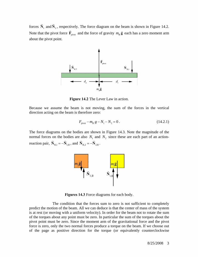
forces and , respectively. The force diagram on the beam is shown in Figure 14.2.
Note that the pivot force 1N 2N
pivotF and the force of gravity Bm g each has a zero moment arm about the pivot point.
Figure 14.2 The Lever Law in action. Because we assume the beam is not moving, the sum of the forces in the vertical direction acting on the beam is therefore zero: pivot B 1 2 0F m g N N− − − = . (14.2.1) The force diagrams on the bodies are shown in Figure 14.3. Note the magnitude of the normal forces on the bodies are also and since these are each part of an action-
reaction pair, , and 1N 2N
B,1 1,B= −N N B,2 2,B= −N N .
Figures 14.3 Force diagrams for each body. The condition that the forces sum to zero is not sufficient to completely predict the motion of the beam. All we can deduce is that the center of mass of the system is at rest (or moving with a uniform velocity). In order for the beam not to rotate the sum of the torques about any point must be zero. In particular the sum of the torques about the pivot point must be zero. Since the moment arm of the gravitational force and the pivot force is zero, only the two normal forces produce a torque on the beam. If we choose out of the page as positive direction for the torque (or equivalently counterclockwise
8/25/2008 3

rotations are positive) then the condition that the sum of the torques about the pivot point is zero becomes 2 2 1 1 0d N d N− = . (14.2.2) The magnitude of the two torques about the pivot point is zero, a condition known as the lever law. Lever Law:
A beam of length is balanced on a pivot point that is placed directly beneath the center of mass of the beam. The beam will not undergo rotation if the product of the normal force with the moment arm to the pivot is the same for each body,
l
1 1 2 2d N d N= . (14.2.3) Example 1: Lever Law Suppose a uniform beam of length 1.0 ml = and mass B 2.0 kgm = is balanced on a pivot point, placed directly beneath the center of the beam. We place body 1 with mass
a distance to the right of the pivot point, and a second body 2 with a distance to the left of the pivot point, such that the beam neither translates nor rotates.
1 0.3 kgm = 1 0.4 md =
2 0.6 kgm = 2d
a) What is the force pivotF that the pivot exerts on the beam? b) What is the distance that maintains static equilibrium? 2d
Solution: a) By Newton’s Third Law, the beam exerts equal and opposite normal forces of magnitude on body 1, and on body 2. The condition for force equilibrium applied separately to the two bodies yields
1N 2N
1 1 0N m g− = , (14.2.4) 2 2 0N m g− = . (14.2.5) Thus the total force acting on the beam is zero, ( )pivot B 1 2 0F m m m g− + + = , (14.2.6) and the pivot force is
8/25/2008 4
(14.2.7) ( )( )( )
pivot B 1 2
22.0 kg 0.3 kg 0.6 kg 9.8 m s 2.8 10 N.
F m m m g−
= + +
= + + ⋅ = × 1
b) We can compute the distance from the Lever Law, 2d
1 1 1 1 1 12
2 2 2
(0.4 m)(0.3 kg) 0.2 m0.6 kg
d N d m g d mdN m g m
= = = = = . (14.2.8)
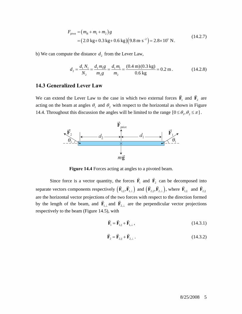
14.3 Generalized Lever Law We can extend the Lever Law to the case in which two external forces and 1F 2F are acting on the beam at angles 1θ and 2θ with respect to the horizontal as shown in Figure 14.4. Throughout this discussion the angles will be limited to the range 1 2[0 , ]θ θ π≤ ≤ .
Figure 14.4 Forces acting at angles to a pivoted beam. Since force is a vector quantity, the forces 1F and 2F can be decomposed into
separate vectors components respectively ( )1, 1,, ⊥F F and ( )2, 2,, ⊥F F , where and 1,F 2,F
are the horizontal vector projections of the two forces with respect to the direction formed by the length of the beam, and 1,⊥F and 2,⊥F are the perpendicular vector projections respectively to the beam (Figure 14.5), with 1 1, 1,⊥= +F F F , (14.3.1) 2 2, 2,⊥= +F F F . (14.3.2)
8/25/2008 5

Figure 14.5 Vector decomposition of forces. The horizontal components of the forces are 1, 1 1cosF F θ= , (14.3.3) 2, 2 2cosF F θ= − , (14.3.4) where our choice of positive horizontal direction is to the right. Neither horizontal force component contributes to possible rotational motion of the beam. The sum of these horizontal forces must be zero, 1 1 2 2cos cos 0F Fθ θ− = . (14.3.5) The perpendicular component forces are 1, 1 1sinF F θ⊥ = , (14.3.6) 2, 2 2sinF F θ⊥ = , (14.3.7) where the positive vertical direction is upwards. The perpendicular components of the forces must also sum to zero, pivot B 1 1 2 2sin sin 0F m g F Fθ θ− + + = . (14.3.8) Only the vertical components 1,F ⊥ and 2,F ⊥ of the external forces are involved in the lever law (but the horizontal components must balance, as in Equation (14.3.5), for equilibrium). Thus the Lever Law can be extended as follows. Generalized Lever Law
A beam of length is balanced on a pivot point that is placed directly beneath the center of mass of the beam. Suppose a force
l
1F acts on the beam a distance to the
right of the pivot point. A second force 1d
2F acts on the beam a distance to the left 2d
8/25/2008 6

of the pivot point. The beam will remain in static equilibrium if the following two conditions are satisfied: 1) The total force on the beam is zero, 2) The product of the magnitude of the perpendicular component of the force with
the distance to the pivot is the same for each force, 1 1, 2 2,d F d F⊥ ⊥= . (14.3.9) The Generalized Lever Law can be stated in an equivalent form, 1 1 1 2 2 2sin sind F d Fθ θ= . (14.3.10) We shall now show that the generalized lever law can be reinterpreted as the statement that the vector sum of the torques about the pivot point is zero when there are just two forces and acting on our beam as shown in Figure 14.6.
S
1F 2F
Figure 14.6 Force and torque diagram. Let’s choose the -direction to point out of the plane of the page then torque pointing out of the page will have a positive -component of torque (counterclockwise rotations are positive). From our definition of torque about the pivot point (Equation 13.2.2), the magnitude of torque due to force
z+z
1F is given by ,1 1 1 1sinS d Fτ θ= . (14.3.11) From the right hand rule this is out of the page (in the counterclockwise direction) so the component of the torque is positive, hence, ( ),1 1 1 1sinS z
d Fτ θ= . (14.3.12)
The torque due to about the pivot point is into the page (the clockwise direction) and the component of the torque is negative and given by
2F
8/25/2008 7

( ),2 2 2 2sinS zd Fτ θ= − . (14.3.13)
The total component of the torque is the sum of the individual torques and is zero, ( ) ( ) ( ), total ,1 ,2 1 1 1 2 2 2sin sin 0S S Sz z z
d F d Fτ τ τ θ θ= + = − = . (14.3.14)
which is equivalent to the Generalized Lever Law, Equation (14.3.10),
1 1 1 2 2 2sin sind F d Fθ θ= . 14.4 Worked Examples Example 14.4.1. Estimate Torque on a Tire iron Your car has a flat and you try to loosen the lugs on the wheel with a tire iron shown in the figure on the left below. You can’t budge the lugs but then you try the 4-way wrench shown in the figure on the right and the lugs loosen. Based on the Figure 14.9, estimate how much torque you needed to apply to loosen the lugs.
Figure 14.9 Force and torque diagram.
Possible Answer: There are many considerations in this problem, and if you’ve had some experience with changing flat tires, you’re aware of what they are. Your experience may suggest that the 4-way is overall easier to use. Start by keeping in mind that the car should be up on a jack, and many jacks don’t supply good overall stability. Applying too much net force, up or down, on the wheel could cause the car to fall off the jack. As an example, for a 1983 VW Rabbit (since departed), the car could be lifted off the jack. Typically, a person can exert an upward force of 2-3 times the person’s weight. So, using the simple wrench on the left and pulling up with both hands warrants caution. Pushing down, the maximum downward force exerted can’t exceed the person’s weight. As an estimate of the net torque, use a force with magnitude equal to your weight and a moment arm of about half a meter. For me, that’s about
. Of course, the angle between the applied force and the wrench should be ; the wrench arm should be horizontal.
500 N m⋅90°
8/25/2008 8

For the 4-way wrench, assume the same magnitude of force applied on each of the two arms used to turn the wrench, one force directed up and the other down. Ideally, this would mean that you apply no net force the car, and falling off the jack is less likely. Also, you would be able to position yourself more or less symmetric about the wheel, making the process a bit more comfortable. (But the forces on your feet wouldn’t be the same – see Example 14.4.3 below.) The forces you exert then form a “couple,” and the torque would be the product of the applied force and the moment arm, times 2 for the two arms of the wrench. From the figure, it looks like the moment arms are about the same as for the simple wrench, so the net torque is roughly your weight times the moment arm of about half a meter times 2, or 1000 N m⋅ ; much easier to undo the lug nuts. Example 14.4.2 Torque on the right leg We want to find the magnitude of the tension in the hip abductor muscles T shown in Figure 14.10.
Figure 14.10 Free body diagram for right leg. The direction α is given. After drawing your free body diagram for the right leg, you are trying to decide what point to compute the torques about. Explain the disadvantages /advantages if you chose each of the points listed below.
a) The center of mass of the leg where the gravitational force lm g acts
b) The contact point with the ground where the normal force N acts c) The point of contact between the acetabulum and the femur where the reaction
force acts R
d) The point where the tension in the hip abductor muscles T act
8/25/2008 9

Answers: An important aspect of this problem, which is a part of a more involved problem, is that we want the tension in the hip abductor muscle, not the reaction force R (magnitude R and angle β ).
a) Using the center of the system is often a good idea, but in this case the leg is only one part of the larger system (the entire body). Specifically, we would need to include in both the force and torque calculations. This can be done, of course, and a decided advantage would be that we obtain
RR from the resulting algebra.
b) Using the contact point with the ground would mean that the normal force N
(and any friction force, not included in the problem but a great aid in standing on one foot) would not exert any torque. However, as in (a), R is then part of the problem.
c) Since the stated goal is to find T , using this contact point for determination of
torques means that R does not enter the torque calculation. If the weight N = N is known or given, then only the torque equation, not any force equations, is needed.
d) Using this point takes out of the torque equation entirely, but T is what we
want, so this would involve extra calculations and determination of . T
R Example 14.4.3: Person standing on a Hill A person is standing on a hill that is sloped at an angle of α with respect to the horizontal (Figure 14.11). The person’s legs are separated by a distance , with one foot uphill and one downhill. The center of mass of the person is at a distance above the ground, perpendicular to the hillside, midway between the person’s feet. Assume that the coefficient of static friction between the person’s feet and the hill is sufficiently large that the person will not slip.
dh
Figure 14.11 Person standing on hill
8/25/2008 10

a) What is the magnitude of the normal force on each foot? b) How far must the feet be apart so that the normal force on the upper foot is just
zero? This is the moment when the person starts to rotate and fall over. Solution: The force diagram on the person is shown in Figure 14.12. Note that the contact forces have been decomposed into components perpendicular and parallel to the hillside. A choice of unit vectors and positive direction for torque is also shown.
Figure 14.12 Free body diagram for person standing on hill Applying Newton’s Second Law to the two components of the net force, 1 2
ˆ : coN N mg αs 0+ −j =
0
(14.4.1) 1 2
ˆ : sinf f mg α+ −i = . (14.4.2) These two equations imply that 1 2 cosN N mg α+ = (14.4.3) 1 2 sinf f mg α+ = . (14.4.4) Evaluating torques about the center of mass,
( ) ( )1 2 2 1 02dh f f N N+ + − = . (14.4.5)
8/25/2008 11

Equation (14.4.5) can be rewritten as
( )1 21 2
2h f fN N
d+
− = . (14.4.6)
Substitution of Equation (14.4.4) into Equation (14.4.6) yields
1 22 ( sin )h mgN N
dα
− = . (14.4.7)
We can solve for by adding Equations 1N (14.4.3) and (14.4.7) and dividing by 2, giving
11 ( sin ) 1cos cos sin2 2
h mg hN mg mgd d
αα α⎛= + = +⎜⎝ ⎠
α ⎞⎟ . (14.4.8)
Similarly, we can solve for by subtracting Equation 2N (14.4.7) from Equation (14.4.3) and dividing by 2, giving
21 cos sin2
hN mgd
α α⎛= −⎜⎝ ⎠
⎞⎟ . (14.4.9)
The normal force as given in Equation 2N (14.4.9) vanishes when
1 cos sin2
hd
α α= , (14.4.10)
which can be solved for the minimum distance between the legs, 2 (tan )d h α= . (14.4.11) In the above figures, 20α = ° , 2 tan 0.73α = and the stick-figure person is very close to tipping over. It should be noted that no specific model for the friction force was used, that is, no coefficient of static friction entered the problem. The two friction forces 1f and 2f were not determined separately; only their sum entered the above calculations.
8/25/2008 12

Example 14.4.4: Static Equilibrium: Rope Between Trees Suppose a rope of mass is connected at the same height to two walls and is allowed to hang under its own weight. At both contact points between the rope and the wall, the rope makes an angle
m = 0.1kg
60θ = ° with respect to the vertical (Figure 14.13). In order to find the tension in the rope at the ends and at the middle of the rope, you will need to think cleverly about what to include as the system in your free body diagram.
Figure 14.13 Rope suspended between two trees
a) What is the tension at the ends of the rope where they are connected to the wall? Include in your answer your free body force diagram. Show all the forces acting on the rope and your choice of unit vectors.
b) What is the tension in the rope at the point midway between the walls? Include in
your answer your free body force diagram. Show all the forces acting on the rope and your choice of unit vectors.
Solution: The key to this problem is in understanding how to choose a force diagram for an extended body. Note that we are trying to find the tension at the ends of the rope and at the midpoint. We defined tension at a point in a rope to be:
The tension in a rope at a distance T (x) x from one end of the rope is the magnitude of the action-reaction pair of forces acting at the point x ,
left, right right,left( ) ( ) ( )T x x x= =F F . (14.4.12) This definition suggests that we need to slice the rope at the midpoint to calculate the tension at the midpoint. Let’s consider then only half the rope. The forces on half the rope are the tension at the end, the tension endT midT at the midpoint and the gravitational force between the half of the rope and the earth, ( / 2)m g . The free body diagram for the left half of the rope is shown in Figure 14.14, with a suitable choice of unit vectors.
8/25/2008 13

Figure 14.14 Free body diagram for left half of rope
Since the rope is in static equilibrium, the sum of the forces is zero. The sum of the components of the forces in the j -direction is zero, end
ˆ : cos ( / 2)m gθ 0− =j T . (14.4.13) Therefore the tension at the end is
( )( )2
end
(0.1kg)/2 9.8 m s( / 2) 0.98 Ncos cos60m g
θ
−⋅= = =
°T . (14.4.14)
The sum of the components of the forces in the ˆ -direction is zero. i end mid
ˆ : sinθ 0− + =i T T . (14.4.15) Substitute Equation (14.4.14) into Equation (14.4.15), yielding
mid( / 2) sin 0
cosm g θ
θ−
+ =T . (14.4.16)
Then solve for tension in the middle of the rope,
( )( )2
mid end( / 2) tan (0.1 kg)/2 9.8 m s tan60 sin 60
0.85 N.
m g θ −= = ⋅ ° =
=
T T ° (14.4.17)
Example 14.4.5 The Knee A man of mass is in a crouch. Assume the man’s weight is equally distributed on both legs. The patellar ligament in the knee is attached to the upper tibia and runs over the kneecap. When the knee is bent, a tensile force,
70kgm =
T , that the ligament exerts on the
8/25/2008 14
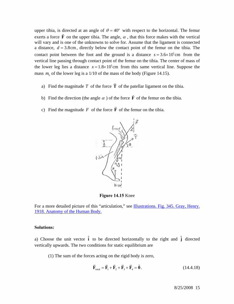
upper tibia, is directed at an angle of 40θ = ° with respect to the horizontal. The femur exerts a force F on the upper tibia. The angle, α , that this force makes with the vertical will vary and is one of the unknowns to solve for. Assume that the ligament is connected a distance, , directly below the contact point of the femur on the tibia. The contact point between the foot and the ground is a distance from the vertical line passing through contact point of the femur on the tibia. The center of mass of the lower leg lies a distance from this same vertical line. Suppose the mass of the lower leg is a 1/10 of the mass of the body (Figure 14.15).
3.8cmd =13.6 10 cms = ×
11.8 10 cmx = ×
Lm a) Find the magnitude T of the force T of the patellar ligament on the tibia. b) Find the direction (the angle α ) of the force F of the femur on the tibia. c) Find the magnitude of the force F F of the femur on the tibia.
Figure 14.15 Knee For a more detailed picture of this “articulation,” see Illustrations. Fig. 345. Gray, Henry. 1918. Anatomy of the Human Body.
Solutions: a) Choose the unit vector to be directed horizontally to the right and i j directed vertically upwards. The two conditions for static equilibrium are (1) The sum of the forces acting on the rigid body is zero, total 1 2 3 4= + + + =F F F F F 0 . (14.4.18)
8/25/2008 15

(2) The vector sum of the torques about any point S in a rigid body is zero,
, total ,1 ,2 ,3S S S S= + + =τ τ τ τ 0 . (14.4.19) The first condition that the sum of the forces is zero becomes
( )
ˆ : sin coˆ : cos sin 1 10 0.
F T
N F T mg
α θ
α θ
s 0− + =
− + −
i
j = (14.4.20)
Since the weight is evenly distributed on the two feet, the normal force on one foot is equal to half the weight, or ( )1 2N = mg ; (14.4.21) the second equation in (14.4.20) becomes
( ) ( )
( )
ˆ : 1 2 cos sin 1 10 0
2 5 cos sin 0.
mg F T mg
mg F T
α θ
α θ
− + − =
− + =
j. (14.4.22)
The torque-force diagram on the knee is shown in Figure 14.16.
Figure 14.16 Torque-force diagram for knee
8/25/2008 16

Choose the point of action of the ligament on the tibia as the point about which to compute torques. Note that the tensile force, T
S, that the ligament exerts on the upper
tibia will make no contribution to the torque about this point . This may help slightly in doing the calculations. Choose counterclockwise as the positive direction for the torque; this is the positive - direction.
S
k Then the torque due to the force F of the femur on the tibia is ( ),1 ,1
ˆ ˆ ˆ ˆsin cos sinS S d F F d Fα α= × = × − − =τ r F αj i j k . (14.4.23)
The torque due to the mass of the leg is ( ) ( ) ( ) ( ),2 ,2
ˆ ˆ ˆ ˆ ˆ10 10 1 10S S Lmg x y mg x mg= × − = − − × − =τ r j i j j k . (14.4.24)
The torque due to the normal force of the ground is ( ) ( ),3 ,3
ˆ ˆ ˆ ˆ ˆ 1 2S S NN s y N s N s mg= × = − − × = − = −τ r ˆj i j j k k . (14.4.25)
(In Equations (14.4.24) and (14.4.25), Ly and Ny are the vertical displacements of the point where the weight of the leg and the normal force with respect to the point ; as can be seen, these quantities do not enter directly into the calculations.)
S
The condition that the total torque about the point vanishes, S , total ,1 ,2 ,3S S S S= + + =τ τ τ τ 0 , (14.4.26) then becomes ( ) ( )ˆ ˆsin 1 10 1 2d F x mg s mgα ˆ+ − =k k k 0 . (14.4.27) The torque equation to be used is then ( ) ( )sin 1 10 1 2 0d F x mg s mgα + − = (14.4.28) The three equations in the three unknowns are summarized below:
( )( ) ( )
sin cos 02 5 cos sin 0
sin 1 10 1 2 0.
F Tmg F T
d F x mg s mg
α θα θ
α
− + =
− + =
+ − =
(14.4.29)
The horizontal force equation, the first in (14.4.29), implies that
8/25/2008 17
sin cosF Tα θ= . (14.4.30) Substituting this into the torque equation, the third of (14.4.29), yields ( ) ( )cos 1 10 1 2 0d T x mg s mgθ + − = . (14.4.31) It is essential that you understand that Equation (14.4.31) is the equation that would have been obtained if we had chosen the contact point between the tibia and the femur as the point about which to determine torques. Had we chosen this point, we would have saved one minor algebraic step. We can solve this Equation (14.4.31) for the magnitude T of the force of the patellar ligament on the tibia,
T
( ) ( )1 2 1 10cos
s mg x mT
d θ−
=g
. (14.4.32)
Inserting numerical values into Equation (14.4.32),
( )( ) ( )( ) ( )( )
( ) ( )
1 12
2
3
3.6 10 m 1 2 1 10 1.8 10 m70kg 9.8m s
3.8 10 m cos 40
3.8 10 N.
T− −
−−
× − ×= ⋅
× °
= ×
(14.4.33)
b) We can now solve for the direction α of the force F of the femur on the tibia as follows. Rewrite the two force equations in (14.4.29) as
( )cos 2 5 sinsin cos .
F mg TF T
α θα θ
= +
= (14.4.34)
Dividing these equations yields
( )2 5 sincos cotansin cos
mg TFF T
θα αα θ
+= = , (14.4.35)
And so
( )
( )( )( ) ( ) ( )( ) ( )
1
2 31
3
2 5 sincotan
cos
2 5 70kg 9.8m s 3.4 10 N sin 40cotan 47 .
3.4 10 N cos 40
mg TT
θα
θ
α
−
−−
+⎛ ⎞= ⎜ ⎟
⎝ ⎠⎛ ⎞⋅ + × °⎜ ⎟= =⎜ ⎟× °⎝ ⎠
°
(14.4.36)
8/25/2008 18

c) We can now use the horizontal force equation to calculate the magnitude of the force of the femur on the tibia from Equation
FF (14.4.30),
( ) ( )
( )
33
3.8 10 N cos 404.0 10 N
sin 47F
× °= =
°× . (14.4.37)
Extra: The algebra in this problem was tedious but not difficult. Such problems are what computers are for. The following is a set of simple (not the most efficient, but the most direct) MAPLE commands for solving the three equations in (14.4.29) simultaneously. > eq1:=-F*sin(alpha)+T*cos(theta)=0; eq2:=m*g/2-F*cos(alpha)+T*sin(theta)-m*g/10=0; eq3:=d*F*sin(alpha)+x*m*g/10-s*m*g/2=0;> theta:=40*Pi/180; m:=70; g:=9.8; s:=.36; x:=.18; d:=.038;> solve({eq1,eq2,eq3},{F,T,alpha}); Note that the angle θ was converted from degrees to radians “by hand.” If you run these commands as given, you will obtain two sets of solutions, one with α in the first quadrant and the other with π α− . In retrospect, this makes sense; if in each equation in (14.4.29) we change the sign of and both trig functions of F α , we get the same equations back. So, pick the solution you want, but you should convert α back to degrees. If this were an 8.012-type problem, we might want to find a symbolic expression for α that did not involve the intermediate numerical calculation of the tension. This is rather complicated algebraically; basically, the last two equations in (14.4.29) are solved for and in terms of
FT α , θ and the other variables (Cramer’s Rule is suggested) and the
results substituted into the first of (14.4.29). The resulting expression is
( ) ( )( )
/ 2 /10 sin 40 2 / 5)cos 40cot
/ 2 /10 cos 402 / 5tan 40
/ 2 /10
s x ds x
ds x
α− °+ °
=− °
= ° +−
(14.4.38)
which leads to the same numerical result, 47α = ° .
8/25/2008 19