chapter 14 a procedure for seismic design of retaining walls · pdf filea procedure for...
TRANSCRIPT

Chapter 14
A procedure for seismic design of retaining walls
S. Caltabiano1, E. Cascone2 & M. Maugeri1 1Dipartimento di Ingegneria Civile e Ambientale, University of Catania 2Dipartimento di Costruzioni e Tecnologie Avanzate, University of Messina
Abstract The available solutions of the limit equilibrium analysis of retaining walls against sliding and tilting allows designing the minimum weight and the geometry of a wall that ensure stability. However, a proper design of a retaining wall in pseudo-static condition must satisfy the stability requirements with a suitable margin of safety against the failure condition, as prescribed by most seismic codes. In particular, in the rotational equilibrium it is necessary to distinguish the contribution due to the earth lateral pressures mobilized along the failure surface and the inertial effect of the soil failure wedge. In this paper a design procedure for retaining walls is proposed, based on a closed form solution and accounting for the sliding safety factor and the evaluation of the driving moments on the wall consistent with the failure mechanisms.
1 Introduction
The problem of the stability of earth retaining walls was originally solved by Coulomb [1] and Rankine [2]. According to these theories the resultant of the active lateral pressures exerted by the backfill soil onto the wall can be written in the form:
2A A A2
2P H K cH Kγ
= − (1)
SEISMIC PREVENTION OF DAMAGE 263
www.witpress.com, ISSN 1755-8336 (on-line) WIT Transactions on State of the Art in Science and Engineering, Vol 8, © 2005 WIT Press
doi:10.2495/1-84564-004-7/14

where γ and c are the unit weight and the cohesion of the soil, H is the height of the retained soil and KA is the active earth pressure coefficient depending on the angle of shear resistance ϕ of the soil. Coulomb’s theory was generalized for cohesionless soils by Mueller-Breslau [3] to account for the frictional interaction between the retained soil and the wall face expressed by the angle δ between the earth thrust and the normal to the wall, the angle β of the internal face of the wall with respect to the vertical, and the slope i of the retained soil. The basic assumptions underlying these solutions are: 1) plane strain conditions; 2) dry and homogeneous backfill soil obeying the Mohr-Coulomb failure criterion; 3) minimum resultant of the lateral stress distribution acting on the wall at failure; 4) plane failure surface inclined at an angle α to the horizontal; 5) soil failure wedge behaving as a rigid body. The accuracy of solutions provided by methods of analysis based on overall equilibrium depends on the failure mechanism assumed for the particular problem at hand. The selection of a proper failure mechanism is therefore of great importance for assessing a reasonable limit load. In fact, once the shape of the failure surface is defined, the problem consists of finding its most critical position. As stated above, in the Coulomb failure mechanism the failure surface is assumed to be a plane. Better estimates of the earth thrust can be derived using more complex failure surface patterns through the method of characteristics developed by Sokolowskii [4] or applying the theorems of limit analysis (Chen [5]). However, the difference in the solutions for the active limit state is negligible, while it is significant for the passive limit state, especially for high values of the soil-wall friction angle δ, the assumption of plane failure surface leading, in this case, to overestimated and, thereby, unconservative values of the passive earth pressure coefficient. Evidence of earthquake-induced damage to retaining structures stimulated the interest for solutions capable of embodying the effect of seismic loading on earth pressures. The theory currently used in the seismic design of retaining walls is represented by the Mononobe-Okabe (M-O) pseudo static approach (Okabe [6]; Mononobe & Matsuo [7]). This theory is an extension of Coulomb’s theory in which the effect of earthquake-induced inertia forces arising in the soil due to seismic loading is taken into account, introducing static body forces. The assumption that soil behaves as a rigid body implies that the seismic acceleration does not vary within the soil wedge and is coincident with the acceleration at the base of the wall. Also in seismic conditions, active earth pressure coefficients obtained using the M-O method and the limit analysis theorems are in close agreement since the log-spiral failure curves obtained by limit analysis are almost planar (Chen & Liu [8]). Planar failure surfaces were also observed in dynamic model tests carried out on shaking tables (Elms & Richards [9]; Oldecop et al. [10]; Cascone [11]; Cascone et al. [12]) and in centrifuge (Bolton & Steedman [13]).
264 SEISMIC PREVENTION OF DAMAGE
www.witpress.com, ISSN 1755-8336 (on-line) WIT Transactions on State of the Art in Science and Engineering, Vol 8, © 2005 WIT Press

In the last decades several theoretical analyses and experimental investigations have been carried out to study the behaviour of retaining walls under both static and seismic conditions. A design approach based on the concept of limited displacements was proposed by Richards & Elms [14] and different relationships are available to evaluate the seismic-induced displacements of retaining walls (Richards & Elms [14]; Zarrabi-Kashani [15]; Whitman & Liao [16]; Crespellani et al. [17]). A pseudo-dynamic analysis was also developed by Steedman & Zeng [18], in which a finite shear wave velocity in the backfill is accounted for. In this analysis, the influence of a change in phase and magnitude of the seismic acceleration on the earth thrust and its point of application was evaluated. Modifications of the M-O approach have recently been suggested to account for the vertical seismic acceleration (Fang & Chen [19]) and the post-peak reduction in soil shear strength along previously formed failure surfaces (Koseki et al. [20]). The available design methods are based on the equilibrium of a soil wedge, and the effect of the wall on the solution is disregarded. This effect is significant since a change in the weight of the wall implies a change in the failure mechanism and in the forces that are to be balanced (Chen & Liu [8]). In this study, the limit equilibrium procedure is used to design the weight of a retaining wall that satisfies equilibrium against sliding and tilting, assuming a vertical and smooth face of the retaining wall (β = δ = 0), and a horizontal backfill (i = 0).
2 Sliding equilibrium of retaining walls
2.1 Static conditions
The limit equilibrium of a retaining wall depends on the geometry of the wall and on the mechanical properties of both the backfill and the foundation soil. In static limit equilibrium the resisting force R at the base of the wall, which depends on the wall weight, is completely mobilized and expressed by the relationship:
A w w btanR F W Wµ ϕ= = = (2) where FA is the friction resistance, Ww is the weight of the wall and µ is the friction coefficient depending on the friction angle ϕb at the contact of the wall base with the foundation soil. The resultant of the stresses mobilized in the backfill along the failure surface represents the driving force D and since δ = 0 is assumed, D is horizontal. Equating D to R, using the Mohr-Coulomb failure criterion with c' = 0, the condition of static incipient failure can be expressed as:
( )2w cot tan
2W Hγµ α α ϕ= − (3)
Introducing the positions:
SEISMIC PREVENTION OF DAMAGE 265
www.witpress.com, ISSN 1755-8336 (on-line) WIT Transactions on State of the Art in Science and Engineering, Vol 8, © 2005 WIT Press

w2
2Y tan tan WH
α ϕγ
= Φ = Γ = (4)
eqn. (3) can be put in the non-dimensional form:
[ ]2Y 1 Y 0µ µΓ Φ + Γ − + Φ = (5) where Γ represents the non-dimensional weight of the wall Γ. Solving eqn. (5) a characteristic value for Γ is obtained:
2 2
01 2 2 1
µ+ Φ − Φ + Φ
Γ = (6)
that represents the minimum non-dimensional weight of the wall that brings the system to limit equilibrium. Γ0 depends only on the angle of shear resistance ϕ and on the friction coefficient µ. Systems characterized by values of Γ smaller than Γ0 result in static instability, whereas systems for which Γ is greater than Γ0 are stable under static conditions.
2.2 Seismic conditions
The forces acting in the soil-wall system under seismic loading are shown in Fig. 1. Under seismic conditions the resisting and the driving forces are given by the following relationships:
( )A h w w hR F k W W kµ= − = − (7)
( ) ( )2s h htan cot tan
2D W k H kγα ϕ α α ϕ= + − = + − (8)
where kh is the coefficient of critical acceleration, defined as the ratio between critical acceleration and gravity.
Equating D to R and using the positions previously introduced (eqn. (5)), the non-dimensional equilibrium equation is obtained:
( ) ( )2h h h hY 1 Y 0k k k kµ µΓΦ − + Γ − − Φ − + Φ − = (9)
Equation (9) reduces to the equilibrium equation (4) for static conditions for kh = 0. For a given soil-wall system, identified by a value of the non-dimensional weight of the wall Γ, assuming kh as a parameter, eqn. (9) admits ∞2 solutions. Thus it is not possible to determine the solution (α, kh) that describes the configuration of the system in the condition of incipient failure. Solving eqn. (8) with respect to the critical seismic coefficient, the following expression is found:
( )( )
2
h 2
Y 1 YY Y 1
kµ µΓΦ + Γ − + Φ
=ΓΦ + Γ + Φ +
(10)
266 SEISMIC PREVENTION OF DAMAGE
www.witpress.com, ISSN 1755-8336 (on-line) WIT Transactions on State of the Art in Science and Engineering, Vol 8, © 2005 WIT Press

Figure 1: Soil-wall system in pseudo static limit equilibrium.
that describes a parabola in the plane (α, kh). The solutions of kh and α can be decoupled by annulling the discriminant of eqn. (9). A second power equation in the unknown kh is then obtained, whose positive root is:
[ ]( )
2 2
2h
( ) ( 1) 2 (1 ) 2 (1 ) ( ) 1k
µ µ µΓ − Φ Γ + − Γ + Φ + ΓΦ + Φ Γ + Φ− Γ +=
Γ − Φ
(11) Equation (11) provides the minimum critical seismic coefficient. Minimizing eqn. (10) with respect to Y, the inclination of the failure plane is determined, independently of kh:
[ ]2 2(1 ) (1 ) 1 ( )1tan1
µ µα
µ
Γ + Φ + ΓΦ + Φ − Γ + Γ + Φ =
ΓΦ + Φ (12)
Equations (11) and (12) represent the solution associated to the limit equilibrium condition, and can be used only in the seismic evaluation of a given soil-wall system. Using the same approach, the problem can be solved to determine the non-dimensional weight of the wall Γ, strictly required for the limit equilibrium condition, when a design seismic coefficient kh is given. In this case, the properties of the soil and the height of the wall are fixed, and using the same minimization procedure, the non-dimensional weight of the wall and the inclination of the failure plane are obtained:
( ) ( ) ( ) ( ) ( )
( )2 2
2
1 2 2 1h h h hk k k k
kh
µ µ
µ
− −Φ + Φ − Φ − + Φ −ΦΓ =
− (13a)
kh WS
WS
Ww
kh Ww
α
FA
N
T H
SEISMIC PREVENTION OF DAMAGE 267
www.witpress.com, ISSN 1755-8336 (on-line) WIT Transactions on State of the Art in Science and Engineering, Vol 8, © 2005 WIT Press

( ) ( ) ( ) ( ) ( )( ) ( )
2 21tan
1h h h h
h h
k k k k
k k
µ µα
µ
Φ − Φ − + Φ − + Φ Φ −=
Φ − + Φ (13b)
Fig. 2 shows the variation of Γ with ϕ = ϕb, for several values of the parameter kh. In particular, the curve associated to kh = 0 (static condition) represents the variation of Γ0. For fixed values of the angle ϕ, Fig. 2 provides evaluating the minimum non-dimensional weight of the wall that in a pseudo-static condition ensures stability.
Figure 2: Minimum wall non-dimensional weight in seismic condition.
2.3 Seismic design of retaining walls
Using the solutions presented above it is possible to proceed to the design of retaining walls. According to most seismic codes, the retaining wall must satisfy equilibrium against sliding and tilting. As far as wall sliding equilibrium is concerned, the safety factor fs is usually defined as:
s s,minRf fD
= ≥ (14)
where fs,min is a reference value given in seismic code. Using eqns. (7) and (8), and fixing a design safety factor fs ≥ fs,min eqn. (14) can be rewritten as follows:
Γ
ϕ 30 35 40 450.10
0.20
0.30
0.40
0.50
0.60
0.70
0.80
0.90
268 SEISMIC PREVENTION OF DAMAGE
www.witpress.com, ISSN 1755-8336 (on-line) WIT Transactions on State of the Art in Science and Engineering, Vol 8, © 2005 WIT Press

( ) ( )2w h hcot tan
2sW k f H kγµ α α ϕ − = ⋅ + − (15)
where the safety factor amplifies the driving forces to guarantee a safe design at working conditions with respect to the failure condition. Dividing both sides of eqn. (15) by fs the following equation is obtained:
( ) ( )2wh hcot tan
2s
W k H kf
γµ α α ϕ
− = + −
(16)
and introducing the new position:
*
sfΓ
Γ = (17)
it is possible to study the design problem as a limit equilibrium condition. In fact, using the non-dimensional formulation previously introduced, the limit equilibrium equation is obtained again:
( ) ( )* 2 *h h h hY 1 Y 0k k k kµ µ Γ Φ − + Γ − − Φ − + Φ − = (18)
Equation (18) is formally identical to eqn. (9) but differs from it in the term Γ*, which represents a weight of the wall smaller than the actual weight required in working conditions. Thus, the correlation between Γ and ϕ shown in Fig. 2 can be used as a design graph, as shown in Fig. 3. Given the characteristics of the soil, for a fixed value of the seismic coefficient kh, the graph allows evaluating the non-dimensional weight Γ* at failure. Using eqn. (17), the parameter Γ is obtained that represents the design value of the weight of the wall at working conditions and that ensures stability with a suitable margin of safety against the failure condition.
2.4 Sample application
To design a gravity retaining wall for any value of the safety factor fs and given soil parameters it is necessary to solve the limit equilibrium problem only once, derive Γ* and multiply its value for the selected safety factor. In this application a wall in the area of the city of Catania, characterized by a seismic coefficient kh = 0.07, is designed for three values of the safety factor fs = 1.3, 1.4 and 1.5. An angle of shear strength of the soil ϕ = 30° and a base friction coefficient µ = tanϕ are assumed. In Fig. 3, for ϕ = 30°, Γ* = 0.742 is obtained and correspondingly the three searched values Γ1.3 = 0.964, Γ1.4 = 1.039 and Γ1.5 = 1.113 are calculated. The real weight of the three walls satisfying the equilibrium with the selected safety factors against sliding, can be obtained from one of the positions given in
SEISMIC PREVENTION OF DAMAGE 269
www.witpress.com, ISSN 1755-8336 (on-line) WIT Transactions on State of the Art in Science and Engineering, Vol 8, © 2005 WIT Press

eqn. (4), once the height of the wall H and the unit weight of the soil γ are known. For the problem at hand, assuming H = 3.5 m and γ = 18 KN/m3 the following values of the wall weight are obtained: W1.3 = 106.28 KN/m, W1.4 = 114.55 KN/m and W1.5 = 122.71 KN/m.
Figure 3: Design chart for non-dimensional weight wall.
2.5 Discussion of results
The design procedure described above allows us to readily evaluate the weight of a retaining wall as the product of the weight strictly required to satisfy the limit equilibrium condition and the safety factor. The wall, therefore, satisfies the sliding equilibrium with the required level of safety but the real failure mechanism of the wall is different from the failure mechanism assumed in the design procedure. In fact, the real wall is characterized by a non-dimensional weight Γ, larger than the non-dimensional weight Γ* introduced in the limit equilibrium equation. As a consequence, the real wall is characterized by a smaller inclination of the failure surface and a larger value of the critical acceleration (Caltabiano [21; Caltabiano et al. [22]). The safety factor has thereby the effect of modifying the failure condition as shown in Fig. 4. Fig. 4a shows the variation of the acceleration coefficient with the weight of the wall. In particular, the value of the critical acceleration coefficient increases for increasing safety factors. Fig. 4b shows that α decreases for increasing values of fs, implying that a larger mass of soil is involved in the actual failure mechanism. This means that the failure plane intercepts the ground surface behind the wall at increasing distances, with the possibility of involving other structures in the collapse.
kh = 0.07 µ = tanϕ
Γ
∗
ϕ 30 35 40 450.20
0.30
0.40
0.50
0.60
0.70
0.80
270 SEISMIC PREVENTION OF DAMAGE
www.witpress.com, ISSN 1755-8336 (on-line) WIT Transactions on State of the Art in Science and Engineering, Vol 8, © 2005 WIT Press

Figure 4: Failure conditions for ϕ = ϕb = 30°: a) kh, b) α.
Table 1 reports the values of the non-dimensional wall weight Γ, of the critical seismic coefficient kh and of the failure plane angle α for the limit equilibrium condition and for the three values of the safety factors assumed in the sample application described above.
Table 1: Results of the design procedure.
fs Γ kh α
1.0 0.742 0.07 56°.83
1.3 0.964 0.138 53°.27
1.4 1.039 0.156 52°.25
1.5 1.113 0.172 51°.29
Increasing fs from 1 to 1.3 the critical acceleration coefficient almost doubles, reaching a value of 0.138; by increasing fs smaller increments of kh are obtained. Consistently, the reduction of the failure plane angle is of about 3° when fs increases from 1 to 1.3, while smaller reductions are obtained for larger values of the safety factor. Fig. 5 shows possible schemes of the failure mechanisms defined in Table 1 for a wall of unit height. The scheme illustrates the increase in the dimensions of the failure wedge for increasing fs, envisaging that if during a seismic event the critical acceleration should be overcome, other structures could suffer from settlements.
kh
Γ
fs = 1
1.31.4
1.5
(a)
fs = 1
α
Γ
1.31.4
1.5
(b)
0.00 0.50 1.00 1.500.00
0.05
0.10
0.15
0.20
0.25
0.00 0.50 1.00 1.5045.00
50.00
55.00
60.00
SEISMIC PREVENTION OF DAMAGE 271
www.witpress.com, ISSN 1755-8336 (on-line) WIT Transactions on State of the Art in Science and Engineering, Vol 8, © 2005 WIT Press

Figure 5: Failure schemes for increasing safety factors.
The usual design of a retaining wall consists in the evaluation of the weight of the wall that at working conditions satisfies limit equilibrium with a required level of safety. Conversely, the proper design of a retaining wall should also evaluate the actual failure conditions of the designed wall to predict the soil-wall behaviour at ultimate conditions.
3 Design procedure for rotational equilibrium
Sliding stability allows determining the minimum weight required at limit equilibrium under static or pseudo static conditions. However, the complete design of a retaining wall requires also rotational (tilting) and vertical (foundation bearing capacity) equilibria to be satisfied. The M-O theory allows evaluating the total earth thrust but does not help to distinguish the contribution due to the earth lateral pressures mobilized along the failure surface that develops in the soil in seismic conditions and the inertial effect of the soil failure wedge. Moreover, the M-O theory is based on a sliding equilibrium and does not provide any information on the point of application of the total earth thrust. The magnitude and the points of application relevant to the two contributions mentioned above are then evaluated to study the rotational equilibrium. In current analysis of retaining walls, according to the Italian seismic code, the seismic active earth thrust SAE is assumed to be the sum of the static active thrust SA applied at 1/3 of the wall height, and the inertial effect of the soil wedge ∆SAE applied at 2/3 of the wall height is evaluated so that the sum of the two contributions is consistent with the M-O theory:
AE A AES S S= + ∆ (19)
0 0.2 0.4 0.6 0.8 1.0 0
0.2
0.4
0.6
0.8
1.0
f =1.0
s
1.31.4
1.5
272 SEISMIC PREVENTION OF DAMAGE
www.witpress.com, ISSN 1755-8336 (on-line) WIT Transactions on State of the Art in Science and Engineering, Vol 8, © 2005 WIT Press

This approach implies that for evaluating the driving forces and moments two distinct failure mechanisms are considered at the same time, but these mechanisms cannot be both true at the same time, since for a given wall weight only a failure mechanism is possible. In the second term of eqn. (8) it is possible to identify a seismic earth pressure coefficient KAE that can be split into the sum of two terms:
( )
( )
cot tan
cotcot tan
AE h
AI h
A
K k
K kK
α α ϕ
αα α ϕ
= ⋅ + − = ⋅
= ⋅ −
(20)
where the term KA takes into account the effect of the distribution of the earth pressures along the seismic failure surface: it is analogous to the static earth pressure coefficient (S), but differs from it because it is evaluated along the pseudo static (PS) failure surface (αS ≠ αPS); the term KAI takes into account the effect of the inertia forces acting in the soil wedge. In Fig. 6 are shown the variations of the three coefficients KA, KAI and KAE obtained using the proposed design procedure and the inertial coefficient ∆KAI defined as:
( ) ( )AI AE PS A SK K Kα α∆ = − (21) adopted in current analysis. For values of kh in the range 0-0.1, KA is not significantly affected by kh and the error involved using the static value (obtained for kh = 0) is negligible. Conversely, for values of kh > 0.1 the effect of the seismic coefficient on the earth pressure coefficient is remarkable (Fig. 6a). As a consequence, by comparison between Fig. 6b and 6d, in which the inertial effect obtained via the proposed design procedure and the current analysis are plotted respectively, it is evident that by increasing the seismic coefficient the latter method underestimates the inertial effect. This is due to an incorrect evaluation of the earth thrust coefficient in seismic conditions. This error can be relevant when the equilibrium against tilting is considered. In fact, the driving moment evaluated according to the Mononobe-Okabe theory and the Italian Seismic code M:
1 23 3A AEM S H S H= + ∆
can be put in the non-dimensional form:
( ) ( ) ( )*3
6 2 2MOA S AE AE PS A S
MM K K K KH
α α αγ⋅
= = + ⋅ ∆ = ⋅ −⋅
(22)
SEISMIC PREVENTION OF DAMAGE 273
www.witpress.com, ISSN 1755-8336 (on-line) WIT Transactions on State of the Art in Science and Engineering, Vol 8, © 2005 WIT Press
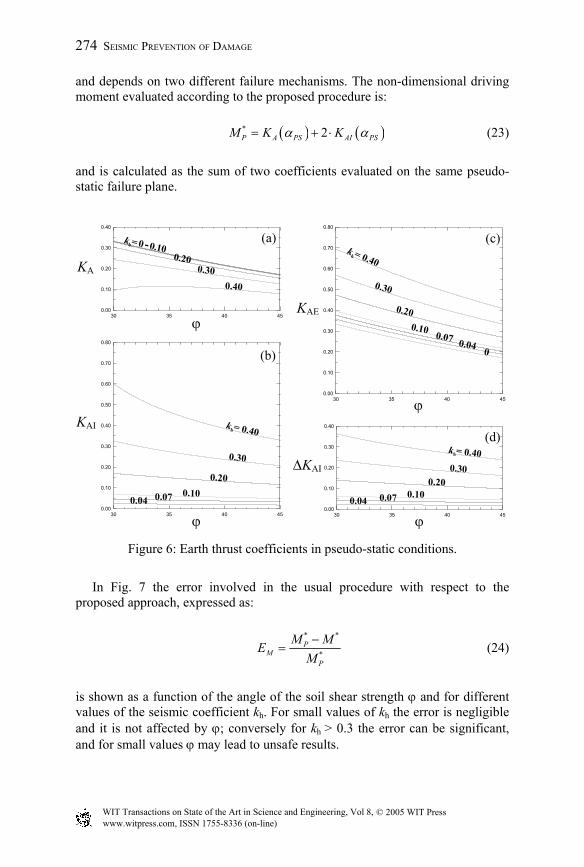
and depends on two different failure mechanisms. The non-dimensional driving moment evaluated according to the proposed procedure is:
( ) ( )* 2P A PS AI PSM K Kα α= + ⋅ (23)
and is calculated as the sum of two coefficients evaluated on the same pseudo-static failure plane.
Figure 6: Earth thrust coefficients in pseudo-static conditions.
In Fig. 7 the error involved in the usual procedure with respect to the proposed approach, expressed as:
* *
*P
MP
M MEM−
= (24)
is shown as a function of the angle of the soil shear strength ϕ and for different values of the seismic coefficient kh. For small values of kh the error is negligible and it is not affected by ϕ; conversely for kh > 0.3 the error can be significant, and for small values ϕ may lead to unsafe results.
KA
ϕ
(a)
ϕ
KAI
(b)
ϕ
KAE
(c)
∆KAI
ϕ
(d)
30 35 40 450.00
0.10
0.20
0.30
0.40
30 35 40 450.00
0.10
0.20
0.30
0.40
0.50
0.60
0.70
0.80
30 35 40 450.00
0.10
0.20
0.30
0.40
0.50
0.60
0.70
0.80
30 35 40 450.00
0.10
0.20
0.30
0.40
274 SEISMIC PREVENTION OF DAMAGE
www.witpress.com, ISSN 1755-8336 (on-line) WIT Transactions on State of the Art in Science and Engineering, Vol 8, © 2005 WIT Press

Figure 7: Error in driving moment evaluation.
4 Conclusions
A new procedure for the seismic design of retaining walls, consistent with the Mononobe-Okabe theory, was proposed. The procedure is based on closed form solutions of the pseudo-static limit equilibrium of walls against sliding (Caltabiano et al. [23]). The design of the retaining structure basically consists in the evaluation of the wall weight necessary to resist earth thrust at limit equilibrium. A minimum non-dimensional weight can be determined for the limit equilibrium condition, then a safety factor fs, defined to meet design requirements but at least equal to the safety factor fs,min imposed by the seismic code, can be applied to provide a certain degree of safety against wall sliding. The choice of the safety factor should be carefully evaluated. Since wall design is based on limit equilibrium conditions, increasing the safety factor has the effect of modifying the reference soil-wall system and, thereby, the actual failure mechanism. In the current design procedure the characteristics of the actual failure mechanism (failure plane angle, critical acceleration) are not usually investigated. However, to safer walls larger failure wedges correspond that might involve adjacent structures in the failure mechanism. The current design procedure of retaining walls is then somewhat tortuous: a wall is designed with reference to limit equilibrium condition for a specified value of the seismic coefficient. A safety factor is then applied to the wall weight to guarantee a larger degree of safety, then a new soil-wall system is obtained with a different failure mechanism from that of the system initially designed for the limit equilibrium condition, and finally the new failure mechanism should be investigated.
ϕ
EM(%)
30 35 40 450
5
10
15
20
SEISMIC PREVENTION OF DAMAGE 275
www.witpress.com, ISSN 1755-8336 (on-line) WIT Transactions on State of the Art in Science and Engineering, Vol 8, © 2005 WIT Press
A simpler procedure might be based on the selection of a convenient value of the maximum design acceleration at ultimate conditions and on the evaluation of the weight of the wall that reaches the limit equilibrium condition at the given design acceleration. According to this procedure, the designed wall will be characterized by a critical acceleration equal to the design acceleration, the actual safety factor resulting in unity. The proposed approach allows also distinguishing the contributions of the earth thrust and of the inertia of the soil wedge. This distinction leads to a more rational design of the walls against tilting, that takes into account the actual driving moments, underestimated in the current approach for large values of the seismic coefficient.
References
[1] Coulomb, C.A. Essai sur une application des règles de maximis et minimis a quelques problèmes de statique relatifs a l’architecture. Memoirs Academie Royal Pres. Division Sav. 7, Paris, France (in French), 1776.
[2] Rankine, W.J.M. On the stability of loose earth, Trans. Royal Society, London, vol. CXLVII, 1857.
[3] Mueller-Breslau, H. Erddruck auf stuetzmauern. Kroener, Stuttgart, 1906 (in German).
[4] Sokolowskii, V.V. Statics of GranularMedia. Pergamon Press, London, 1965.
[5] Chen, W.F. Limit Analysis and Soil Plasticity. Elsevier, Amsterdam, 1975. [6] Okabe, S. General theory of earth pressure J. Japanese Society of Civil
Engineering, 1926, 12, No. 1. [7] Mononobe, N. & Matsuo, H., On the determination of earth pressure
during earthquakes. Proc. World Engineering Conference, Vol. IX, paper No. 388, 1929.
[8] Chen, W.F. & Liu, X.L. Limit Analysis in Soil Mechanics, Elsevier, Amsterdam, 1990.
[9] Elms, D.G. & Richards, R. Jr. Seismic design of retaining walls, Proceedings of the. Conference on Design and Performance of Earth Retaining Structures, Cornell University, Ithaca, NY, ASCE Geo-Special Publication No. 25, 1990, pp. 854-871.
[10] Oldecop, L., Zabala, F. & Almazan, J.L. Shaking table test on small prototype of soil retaining wall, Proceedings of the 11th World Conference on Earthquake Engineering. Mexico City, 1996, paper No. 1094.
[11] Cascone, E. Model tests and modelling of the dynamic behaviour of retaining walls, Ph.D. Thesis, University of Catania, 1996 (in Italian).
[12] Cascone, E., Lo Grasso, A.S. & Maugeri, M. Dynamic model tests on gravity retaining walls with various surcharge conditions. Proceedings 4th Int. Conference on Recent Advances in Geotechnical Earthquake Engineering and Soil Dynamics, San Diego, 2001, paper No. 7.12.
276 SEISMIC PREVENTION OF DAMAGE
www.witpress.com, ISSN 1755-8336 (on-line) WIT Transactions on State of the Art in Science and Engineering, Vol 8, © 2005 WIT Press
[13] Bolton, M.D. & Steedman, R.S. Modelling the seismic resistance of retaining structures, Proceedings of the 11th Int. Conference on Soil Mechanics and Foundation Engineering. San Francisco, 1985, Vol. IV, pp. 1845-1848.
[14] Richards, R.R. Jr. & Elms, D.G. Seismic behaviour of gravity retaining walls, Journal of the Geotechnical Engineering Division, 1979, 105, No. 4, pp. 449-464.
[15] Zarrabi-Kashani, K. Sliding of gravity retaining walls during earthquake considering vertical acceleration and changing inclination of failure surface, M.S. Thesis, Dept. of Civ. Eng., MIT, Cambridge, USA, 1979.
[16] Whitman, R.V. & Liao, S. Seismic design of gravity retaining walls. Proceedings of the 8th World Conference on Earthquake Engineering. San Francisco, 1984, Vol. III, pp. 533-540.
[17] Crespellani, T., Madiai, C. & Vannucchi, G. Earthquake destructiveness potential factor and permanent displacements of gravity retaining walls, Proc. Analysis and Design of Retaining Structures Against Earthquakes, Washington, ASCE Geo-Special Publ. No. 60, 1996, pp. 124-133.
[18] Steedman, R.S. & Zeng, X. The influence of phase on the calculation of pseudo static earth pressure on a retaining wall, Géotechnique, 1990, 40, No. 1, pp. 103-112.
[19] Fang, Y.-S. & Chen, T.-J. Modification of Mononobe-Okabe theory. Géotechnique, 1995, 45, No. 1, pp. 165-167.
[20] Koseki, J., Tatsuoka, F., Munaf, Y., Tateyama, M. & Kojima, K. A modified procedure to evaluate active earth pressure at high seismic loads, Soils and Foundations, 1998, Special Issue on Geotechnical Aspects of the January 17 1995 Hyogoken-Nanbu earthquake, No. 2, pp. 209-216.
[21] Caltabiano, S. Modelling of the seismic behaviour of retaining walls with particular boundary conditions, Ph.D. Thesis, University of Catania, 1999 (in Italian).
[22] Caltabiano, S., Cascone, E. & Maugeri, M. Seismic stability of retaining walls with surcharge. Soil Dynamics and Earthquake Engineering, 2000, 20, No. 5-8, pp. 469-476.
[23] Caltabiano S., Cascone E. & Maugeri M. (2004). Pseudo static analysis of earth retaining walls subjected to surface surcharge. Submitted for publication.
SEISMIC PREVENTION OF DAMAGE 277
www.witpress.com, ISSN 1755-8336 (on-line) WIT Transactions on State of the Art in Science and Engineering, Vol 8, © 2005 WIT Press