chapter 13 feb28
TRANSCRIPT

8/14/2019 Chapter 13 Feb28
http://slidepdf.com/reader/full/chapter-13-feb28 1/23
Chapter 13.1
Chapter 13 Example Circuits
13.1 Limiting Maximum Pressure
13.1.1 Relief Valve
Maximum pressure is the relief valve setting (ideal)Operating pressure is dictated by the burden
Figure 13.1 Relief Valve to limit pressure
13.1.2 Hydraulic FuseOne shot affair
Overload protection13.1.3 Pressure Compensating Pump
Maximum pressure is set by the deadhead value
Figure 13.2 Deadhead pressure to limit system pressure

8/14/2019 Chapter 13 Feb28
http://slidepdf.com/reader/full/chapter-13-feb28 2/23
Chapter 13.2
13.2 Unloading Circuits
13.2.1 Bypass system
This circuit unloads the pump when the ram reaches the end of its stroke
Normal operation Pump unloaded
Figure 13.3 Unloading valve to limit pressure
13.2.2 Balanced Relief ValveIn the neutral position, the pump is unloaded

8/14/2019 Chapter 13 Feb28
http://slidepdf.com/reader/full/chapter-13-feb28 3/23
Chapter 13.3
Figure 13.4 Balanced relief valve
13.2.3 Electronic UnloadingOperator manually switches valve to position shown. LS1 is activated. Piston
moves to the right until LS1 is engaged which, in turn, actuates the pump valve solenoid.The valve is opened dumping flow to tank at low pressure. To reverse, LS1 is de-activated, closing the solenoid valve.
To solenoid
To LS1
To LS2
LS2 LS1
Tosolenoid
ToLS1
ToLS2
LS2 LS1
Tosolenoid
ToLS1
ToLS2
LS2 LS1
Normal Operation PSI activated, Solenoid engages
Figure 13.5 Unloading pressure using electronic limit switches
8/14/2019 Chapter 13 Feb28
http://slidepdf.com/reader/full/chapter-13-feb28 4/23
Chapter 13.4
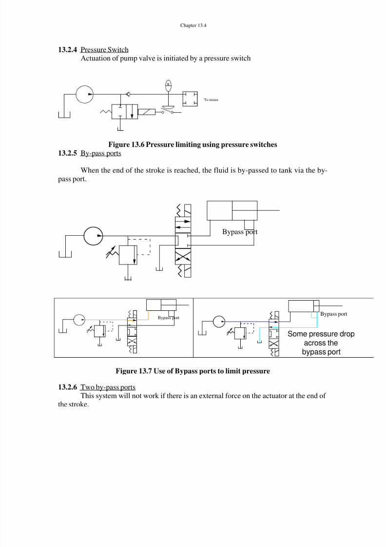
13.2.4 Pressure SwitchActuation of pump valve is initiated by a pressure switch
To motor
Figure 13.6 Pressure limiting using pressure switches13.2.5 By-pass ports
When the end of the stroke is reached, the fluid is by-passed to tank via the by-pass port.
Bypass por t
Bypass portBypass port
Some pressure dropacross the
bypass port
Figure 13.7 Use of Bypass ports to limit pressure
13.2.6 Two by-pass portsThis system will not work if there is an external force on the actuator at the end of
the stroke.

8/14/2019 Chapter 13 Feb28
http://slidepdf.com/reader/full/chapter-13-feb28 5/23
Chapter 13.5
Bypass port
Figure 13.8 Bypass port example
13.3 High-Low Circuits
This circuit is used to provide two output speeds. RV1 is set a low value, RV2 ishigh. At low system pressure, RV1 and RV2 are not active, The flow to the system is thesum of both pumps. As the system pressure approaches RV1, pump RV1 is unloaded atPRV1 and only flow from pump RV2 is delivered to the actuator. Thus we have highflow rates at low pressure and low flow rates at high pressure.
RV1
RV2
High
Low
Q1
Q2
Q = Q 1 + Q2
Rapid advance, lowpressure
RV1
RV 2
High
Low
Pump unloadsat RV1
Q1
Q2
Q = Q 1
Slow advancehigher pressure
Figure 13.9 High-Low Circuit

8/14/2019 Chapter 13 Feb28
http://slidepdf.com/reader/full/chapter-13-feb28 6/23
Chapter 13.6
In this case, the pump unloads at a low pressure when the pressure at RV1 is reached.
RV1
RV2
High
Low
Q1
Q2
Q = Q 1 + Q2
Rapid advance, lowpressure
RV1
RV 2
High
Low
Pump unloadsAt tank
Q1
Q2
Q = Q 1
Slow advancehigher pressure
Figure 13.10 Second High – low circuit
13.4 Circuits for controlling cylinder pressureIn this circuit, the pump relief valve is for pump protection. RV1 and RV2 limit
pressure in each of the lines.

8/14/2019 Chapter 13 Feb28
http://slidepdf.com/reader/full/chapter-13-feb28 7/23
Chapter 13.7
RV1 RV2
Figure 13.11 Pressure limits in each branch
13.5 Multi-branch CircuitsHere is the case of a single pump providing fluid to several circuits. Only one
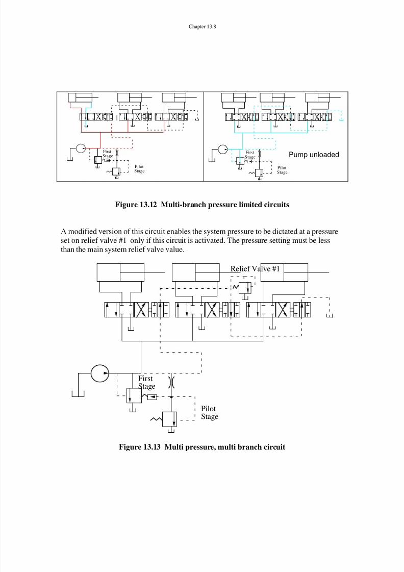
circuit is activated at a time; if two are activated, the fluid will travel to the system withthe lowest burden resistance. In neutral (all valves), the pilot pressure on the first stage islow, unloading the pump. If any valve is actuated, the pilot line is blocked, the first stagerelief valve is de-activated and thus the pilot stage becomes the relief valve for thesystem.
PilotStage
FirstStage
8/14/2019 Chapter 13 Feb28
http://slidepdf.com/reader/full/chapter-13-feb28 8/23
Chapter 13.8
PilotStage
FirstStage
PilotStage
FirstStage Pump unloaded
Figure 13.12 Multi-branch pressure limited circuits
A modified version of this circuit enables the system pressure to be dictated at a pressureset on relief valve #1 only if this circuit is activated. The pressure setting must be lessthan the main system relief valve value.
PilotStage
FirstStage
Relief Valve #1
Figure 13.13 Multi pressure, multi branch circuit

8/14/2019 Chapter 13 Feb28
http://slidepdf.com/reader/full/chapter-13-feb28 9/23
Chapter 13.9
13.6 Use of Pressure Reducing ValvesThe pressure in cylinder 1 is limited by the main relief valve. Pressure in cylinder
#2 is limited by the setting of the pressure reducing valve. Note that the pressure in circuit#2 is controlled as well as limited
cylinder1
cylinder2
P rv
P 1
P 2
P 1 and P 2
less thanP rv
P rv
P 1
P 2
P 2 = P rv
P 1 > P rv
Figure 13.14 Pressure reducing circuit
13.7 Complex Multi-Pressure SystemIn the neutral position, RV1 sets the maximum pressure. Switching the Relief
Valve Directional Control Valve, will enable RV2 or RV3 and thus, maximum systempressure is changed

8/14/2019 Chapter 13 Feb28
http://slidepdf.com/reader/full/chapter-13-feb28 10/23
Chapter 13.10
FirstStage
DCV1
DCV2
RV2 RV3
RV1
FirstStage
DCV1
DCV2
RV2 RV3
RV1
Main RV1sets pressure
in neutralFirstStage
DCV1
DCV2
RV2 RV3
RV1
RV2 limitspressure
FirstStage
DCV1
DCV2
RV2 RV3
RV1
RV3 limitspressure
Figure 13.15 Multi-Pressure circuit
8/14/2019 Chapter 13 Feb28
http://slidepdf.com/reader/full/chapter-13-feb28 11/23
Chapter 13.11
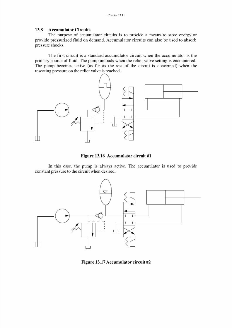
13.8 Accumulator CircuitsThe purpose of accumulator circuits is to provide a means to store energy or
provide pressurized fluid on demand. Accumulator circuits can also be used to absorbpressure shocks.
The first circuit is a standard accumulator circuit when the accumulator is theprimary source of fluid. The pump unloads when the relief valve setting is encountered.The pump becomes active (as far as the rest of the circuit is concerned) when thereseating pressure on the relief valve is reached.
Figure 13.16 Accumulator circuit #1
In this case, the pump is always active. The accumulator is used to provide
constant pressure to the circuit when desired.
Figure 13.17 Accumulator circuit #2
8/14/2019 Chapter 13 Feb28
http://slidepdf.com/reader/full/chapter-13-feb28 12/23

8/14/2019 Chapter 13 Feb28
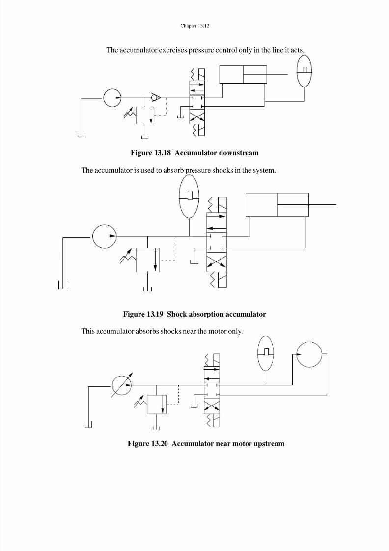
http://slidepdf.com/reader/full/chapter-13-feb28 13/23
Chapter 13.13
13.9 Circuits for Flow Control
13.9.1 Regenerative CircuitsWhen the regenerative flow position of the DCV is activated, both sides if the
actuator are at the same pressure. Flow from the rod end of the actuator is forced back tothe blank end effectively increasing the flow to (and the velocity of) the ram. This is atthe expense of the system pressure which must increase to meet the burden forcerequirements.
Regenerative flow(detent position)
A A1 2
PP
A A1 2
PP
Normaloperation
A A1 2
PP
Regenerationposition
Figure 13.21 Regenerative circuit
Now let P be the system pressure. Let
F1 = P A1F2 = P A2and F L = Burden force
Then F 1 + F2 +- F L or P A1 - P A2 = FLor P ( A1 - A2 ) = FL
8/14/2019 Chapter 13 Feb28
http://slidepdf.com/reader/full/chapter-13-feb28 14/23
Chapter 13.14
Thus P =FL
A1 - A2The total flow to the actuator is Q pump + Q actuator (ram side)
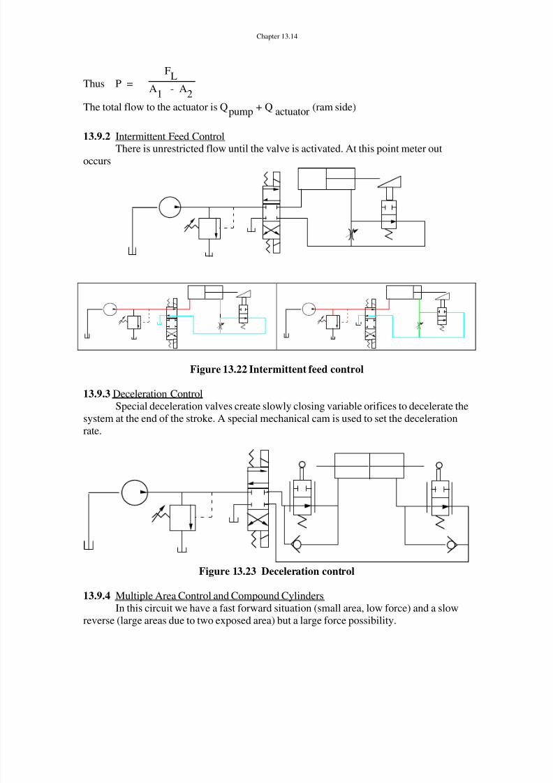
13.9.2 Intermittent Feed ControlThere is unrestricted flow until the valve is activated. At this point meter out
occurs
Figure 13.22 Intermittent feed control
13.9.3 Deceleration Control
Special deceleration valves create slowly closing variable orifices to decelerate thesystem at the end of the stroke. A special mechanical cam is used to set the decelerationrate.
Figure 13.23 Deceleration control
13.9.4 Multiple Area Control and Compound CylindersIn this circuit we have a fast forward situation (small area, low force) and a slow
reverse (large areas due to two exposed area) but a large force possibility.
8/14/2019 Chapter 13 Feb28
http://slidepdf.com/reader/full/chapter-13-feb28 15/23
Chapter 13.15
Sealed
SealedSealed
Figure 13.24 Transformer circuit
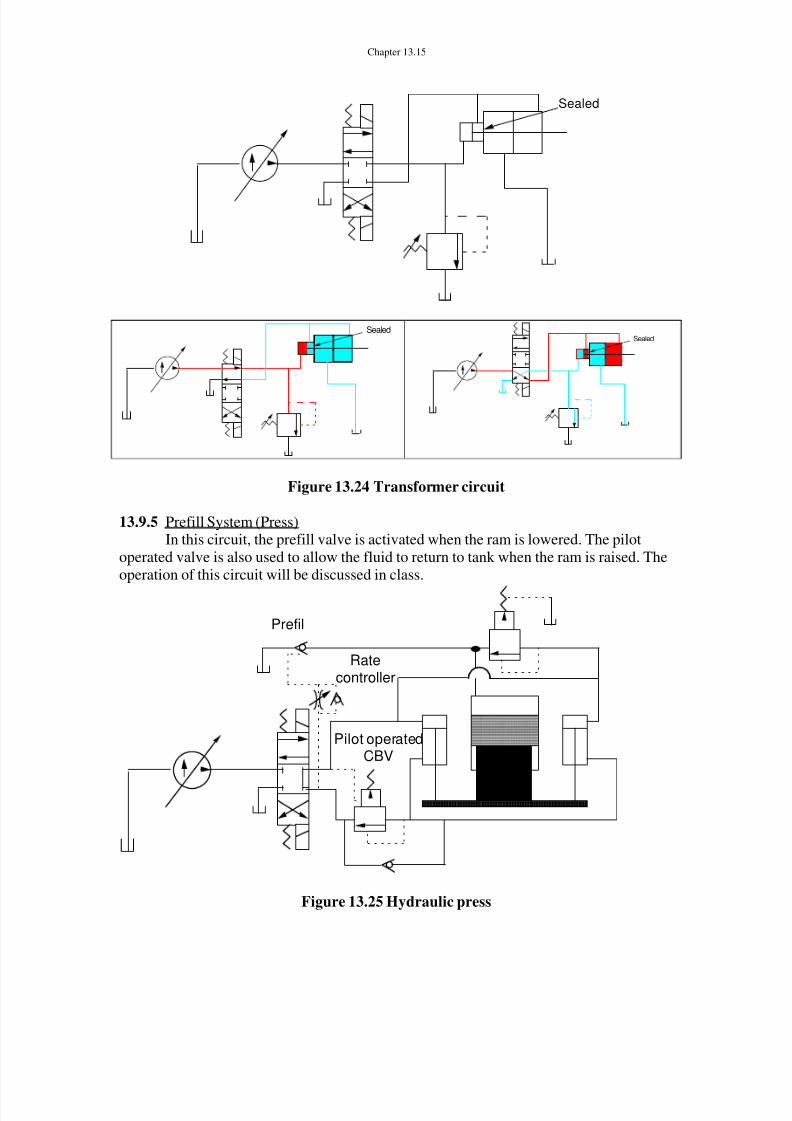
13.9.5 Prefill System (Press)In this circuit, the prefill valve is activated when the ram is lowered. The pilot
operated valve is also used to allow the fluid to return to tank when the ram is raised. Theoperation of this circuit will be discussed in class.
Prefil
Ratecontroller
Pilot operatedCBV
Figure 13.25 Hydraulic press
8/14/2019 Chapter 13 Feb28
http://slidepdf.com/reader/full/chapter-13-feb28 16/23
Chapter 13.16
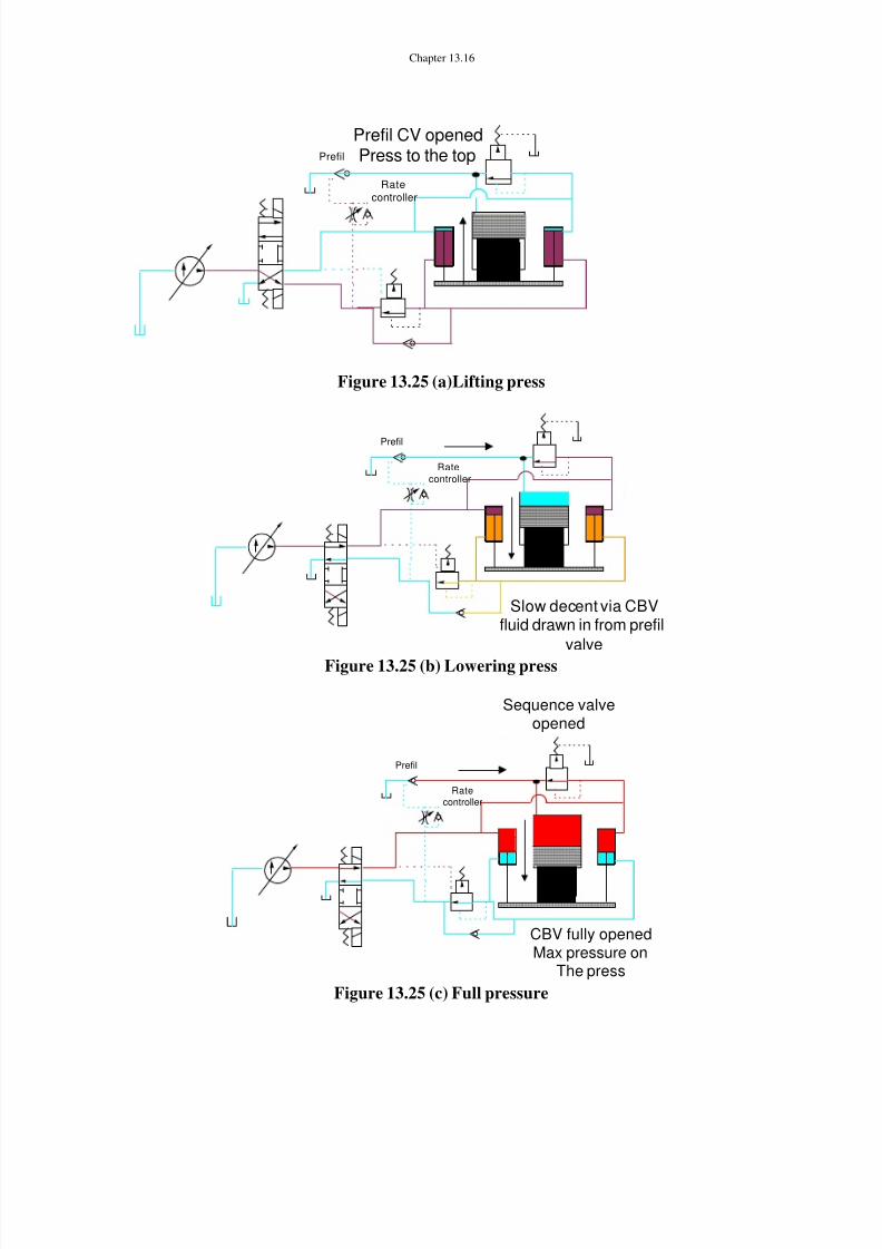
Prefil
Ratecontroller
Prefil CV openedPress to the top
Figure 13.25 (a)Lifting press
Prefil
Ratecontroller
Slow decent via CBVfluid drawn in from prefil
valveFigure 13.25 (b) Lowering press
Prefil
Ratecontroller
CBV fully openedMax pressure on
The press
Sequence valveopened
Figure 13.25 (c) Full pressure

8/14/2019 Chapter 13 Feb28
http://slidepdf.com/reader/full/chapter-13-feb28 17/23
Chapter 13.17
Rate controllerSlowly opensCheck valve
and slowly decompressesthe pressure at the
top of the pressPrefil
Ratecontroller
Pilot operatedCBV
Figure 13.25 (d) Decompression
13.9.6 Flow Divider Circuits .Flow divider circuits split the pump flow into two paths, hopefully independent of
the loading conditions. The first circuit is meter in. The second, a meter out configuration.
Figure 13.26 Flow divider circuit
Figure 13.27 Flow divider circuit using motors
13.9.7 Basic Meter out (Control)

8/14/2019 Chapter 13 Feb28
http://slidepdf.com/reader/full/chapter-13-feb28 18/23
Chapter 13.18
This is a simple way of making a pressure compensated flow control valve in ameter out configuration. The pressure reducing valve maintains a constant pressure dropacross the orifice
t consQTherefore
t consaisPbut
P AC Q d
tan
tan
2
1
1
P 1
P t = 0
Figure 13.28 Meter-out circuit
13.10 Other Circuits13.10.1 Sequence circuits
When cylinder #1 is fully retracted, the pressure increases until the sequence valveis activated. Cylinder #2 then moves.
cylinder#1
cylinder#2

8/14/2019 Chapter 13 Feb28
http://slidepdf.com/reader/full/chapter-13-feb28 19/23
Chapter 13.19
1. First actuator moves
2. Second actuator doesnot move
1. When actuator bottoms outpressure builds up
2. Sequence valveopens
3. Second actuator moves
Figure 13.29 Sequence circuit
13.10.2 Synchronization Circuits
Is this circuit adequate for flow synchronization of two cylinders?
cylinder#1
cylinder#2
Answer. No See below.
cylinder#1
F1P1
F2P1
F1 > F 2
For F1 > F2, cylinder #2will not move
Figure 13.30 Synchronization with no flow control

8/14/2019 Chapter 13 Feb28
http://slidepdf.com/reader/full/chapter-13-feb28 20/23
Chapter 13.20
NOTE Synchronization can only be absolutely ensured by using servo-systems (closedloop control)
This is a master slave circuit where the area of the rod end of the first cylindermust exactly match the area of the blank end of the second cylinder. A problem occurs if
leakage is present.cylinder#1
cylinder#2
A1
A2
A1 =A2
Q1 = A1 * V1
Q 2 = Q 1 = A2 *V2
but since A1 = A2the two velocities are the same
Q 1
Q2
Figure 13.31 Master – slave circuit
Other methods of synchronization include the use of meter in and meter out circuits (flowdividers.) The accuracy strongly depends on the flow divider/combiner accuracy.
P s = constant P s = constant
Figure 13.32 Meter in and flow divider circuits to synchronize flowNote this circuit also isolates the two loads so that changes in the pressures at the
motors will not affect the other circuit
13.10.3 Multi-load circuitsTo isolate multi-load circuits, we must unsure that the pressure at the pump is always
constant. Thus changes in the flow or load pressure in one circuit will not affect theothers. THIS IS VERY IMPORTANT. Figure 13.22 demonstrates one way of accomplishing this.
8/14/2019 Chapter 13 Feb28
http://slidepdf.com/reader/full/chapter-13-feb28 21/23
Chapter 13.21
Circuit 1
Circuit 2
Circuit 3
P s
Q1
Q2
Q3
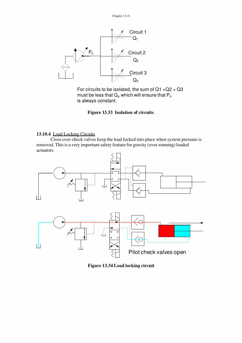
For circuits to be isolated, the sum of Q1 +Q2 + Q3must be less that Q p which will ensure that P s
is always constant.
Figure 13.33 Isolation of circuits .
13.10.4 Load Locking CircuitsCross over check valves keep the load locked into place when system pressure is
removed. This is a very important safety feature for gravity (over-running) loadedactuators.
Pilot check valves open
Figure 13.34 Load locking circuit

8/14/2019 Chapter 13 Feb28
http://slidepdf.com/reader/full/chapter-13-feb28 22/23
Chapter 13.22
13.10.5 Counter-Balance circuitMaintains a constant controlled back pressure on the actuator.
P cbv
P
P < P cbv
Load is locked
P cbv
P
P > P cbv
Actuator can now move but witha back pressure of P cbv
Figure 13.35 Counterbalance circuits
This circuit uses a balanced counterbalance valve which slowly opens only if the
upstream pressure is high. At low upstream pressures, a constant back pressure exists(regular counter-balance valve).

8/14/2019 Chapter 13 Feb28
http://slidepdf.com/reader/full/chapter-13-feb28 23/23
Chapter 13.23
For P large
CBV fullyopened
P
For P smallCBV partially
opened just sufficient tobalance the runaway load
P
Figure 13.36 Pilot operated counterbalance circuits