chapter 13 bridge load rating contents - civil engineering manual... · chapter 13 bridge load...
TRANSCRIPT
Bridge Design Manual M 23-50.02 Page 13-i May 2008
Chapter 13 Bridge Load Rating Contents13.1 General 13.1-1
13.1.1 WSDOT Rating (LRFR) 13.1-213.1.2 NBI Rating (LFR) 13.1-8
13.2 Special Rating Criteria 13.2-113.2.1 Dead Loads 13.2-113.2.2 Live Load Distribution Factors 13.2-113.2.3 Reinforced Concrete Structures 13.2-113.2.4 Concrete Decks 13.2-113.2.5 Concrete Crossbeams 13.2-113.2.6 In-Span Hinges 13.2-213.2.7 Concrete Box Girder Structures 13.2-213.2.8 Prestressed Concrete Girder Structures 13.2-213.2.9 Concrete Slab Structures 13.2-213.2.10 Steel Structures 13.2-213.2.11 Steel Floor Systems 13.2-213.2.12 Steel Truss Structures 13.2-213.2.13 Timber Structures 13.2-313.2.14 Widened or Rehabilitated Structures 13.2-313.2.15 13.2-3
13.3 Load Rating Software 13.3-1
13.4 Load Rating Reports 13.3-3
13.5 Bibliography 13.5-1
Appendix AAppendix 13.4-A1 Bridge Rating Summary 13.4-A1-1

Page 13-ii Bridge Design Manual M 23-50.02 May 2008
Contents Chapter 13
Bridge Design Manual M 23-50.02 Page 13.1-1 May 2008
Chapter 13 Bridge Load Rating
13.1 GeneralBridge Load Rating is a procedure to evaluate the adequacy of various structural components to carry predetermined live loads. The Bridge Load Rating Engineer in the WSDOT Bridge Preservation Office is responsible for the bridge inventory and load rating of existing and new bridges in accordance with the NBIS and the AASHTO Manual for Condition Evaluation of Bridges, latest edition. As presently required, only elements of the superstructure will be rated. Generally, the superstructure shall be defined as all structural elements above the column tops including drop crossbeams.
In order to provide a baseline rating for new bridges, load ratings are required for all new bridges, widened (one lane width or more throughout the length of the bridge), or rehabilitated bridges where the rehabilitation alters the load carrying capacity of the structure. The carrying capacity of a widened or rehabilitated structure shall equal or exceed the capacity of the existing structure.
The Bridge Design Section does not load rate new bridges during the design phase. However, copies of the computer models used in the design process shall be submitted to the Bridge Load Rating Engineer in the Bridge Preservation Section for the more complex structures where computer models were used in the design process.
The Bridge Preservation Office is responsible for maintaining an updated bridge load rating throughout the life of the bridge based on current bridge condition. Conditions of existing bridges change over time, resulting in the need for reevaluation of the load rating. Such changes may be caused by damage to structural elements, extensive maintenance or rehabilitative work, or any other deterioration identified by the Bridge Preservation Office through their regular inspection program.
This criteria applies only to concrete and steel bridges. For timber bridges, rating procedure shall be as per Chapters 6 and 7 of the 1994 AASHTO Manual for Condition Evaluation of Bridges.
Structural elements as defined above shall be evaluated for flexural, vertical shear, and torsional capacities based on Load Resistance Factor Design (LRFR) as outlined in the AASHTO 1989 Guide Specifications for Strength Evaluation of Existing Steel and Concrete Bridges and Load Factor Design (LFD) as outlined in the latest AASHTO Manual for Condition Evaluation of Bridges. Consider all reinforcing, including temperature/distribution reinforcement, in the rating analysis.
By definition, the adequacy or inadequacy of a structural element to carry a specified truck load will be indicated by the value of its rating factor (RF); that is, whether it is greater or smaller than 1.0. For a specific loading, the lowest RF value of the structural elements will be the overall rating of the bridge.

Page 13.1-2 Bridge Design Manual M 23-50.02 May 2008
Bridge Load Rating Chapter 13
13.1.1 WSDOT Rating (LRFR)Ratings shall be performed per the 1989 AASHTO Guide Specifications for Strength Evaluation of Existing Steel and Concrete Bridges. All bridges, except timber, shall be rated based on the Strength method.
A. Strength Method (LRFR)
The basic rating equations shall be:
RFL 1 I
R D Sn
L
DL !=
+
-
ccU^ h
When rating the full section of a bridge, like box girders, or crossbeams, which have two or more lanes, the following formulas apply for the overload trucks:
RFL 1 I
R D S L 1 IL
n DL L Legal Load!=
+
- - +
cc cU
^
^
h
h
The formulas for the overloads assume that there is one overload truck in one lane, and legal trucks occupy the remaining lanes. Trucks shall be placed, in the lanes, in a manner that produces the maximum forces.
Where:
R.F. = Rating Factor (Ratio of Capacity to Demand)Rn = Nominal Capacity of SectionD = Calculated Dead LoadS = Secondary PrestressingL = Calculated Live LoadΦ = Resistance Factor (Capacity Reduction Factor)γDL = Dead Load Factor.γL = Live Load FactorγP = Prestress FactorI = Impact
*For continuous structures, a one-half support width moment increase is to be used.
Bridge Design Manual M 23-50.02 Page 13.1-3 May 2008
Chapter 13 Bridge Load Rating
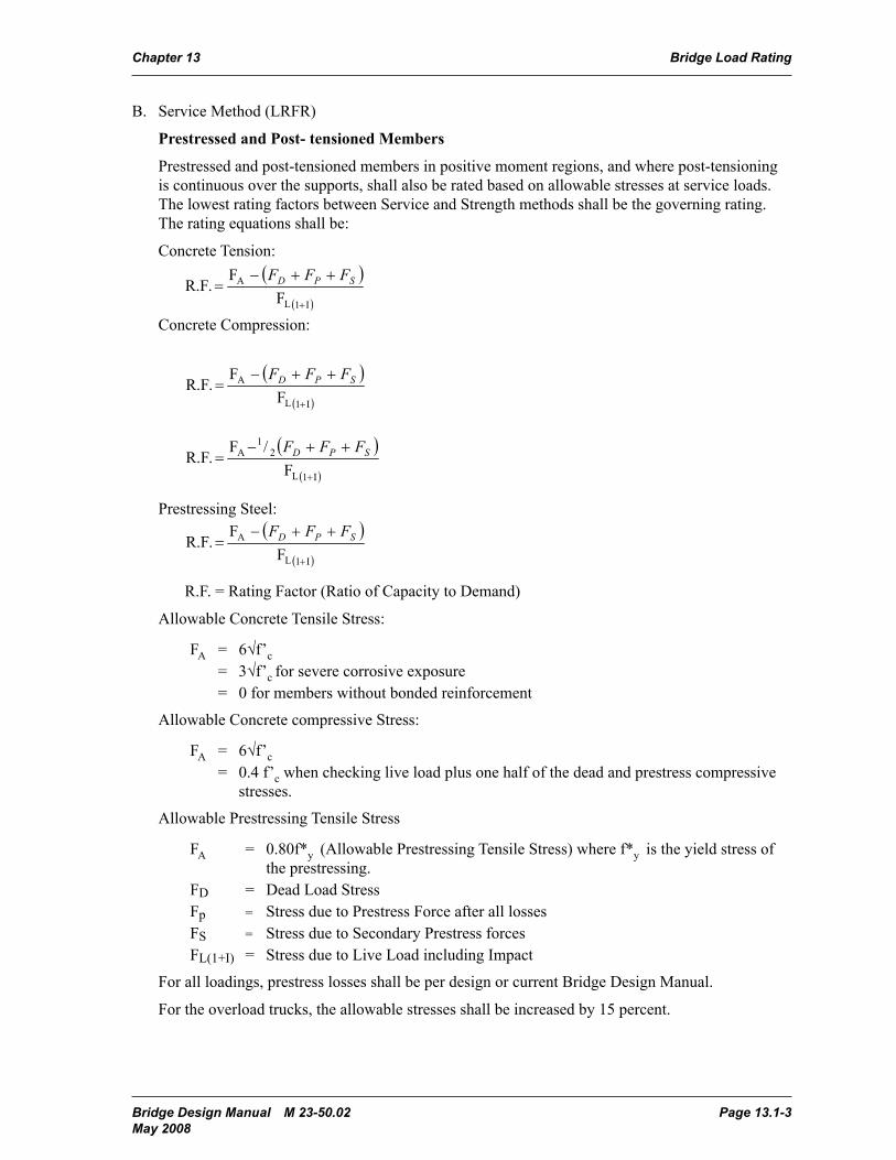
B. Service Method (LRFR)
Prestressed and Post- tensioned Members
Prestressed and post-tensioned members in positive moment regions, and where post-tensioning is continuous over the supports, shall also be rated based on allowable stresses at service loads. The lowest rating factors between Service and Strength methods shall be the governing rating. The rating equations shall be:
Concrete Tension:
I1LL
PPDLDLn
MγMγMγΦM
R.F.
I1LL
PPDLDLn
VγVγVγΦV
R.F.
I1LL
LoadLegalI1LLPPDLDLn
MγMγMγMγΦM
R.F.
I1LL
LoadLegalI1LLPPDLDLn
VγVγVγVγΦV
R.F.
I1L
A
FF
.R.F
SPD FFF
I1L
A
FF
.R.F
SPD FFF
I1L
21
A
F/F
.R.F
SPD FFF
I1L
A
FF
.R.F
SPD FFF
I1L
DLn
LγSDγΦR
.R.F
L
DA
FFF
.R.F
L12550I
Concrete Compression:
I1LL
PPDLDLn
MγMγMγΦM
R.F.
I1LL
PPDLDLn
VγVγVγΦV
R.F.
I1LL
LoadLegalI1LLPPDLDLn
MγMγMγMγΦM
R.F.
I1LL
LoadLegalI1LLPPDLDLn
VγVγVγVγΦV
R.F.
I1L
A
FF
.R.F
SPD FFF
I1L
A
FF
.R.F
SPD FFF
I1L
21
A
F/F
.R.F
SPD FFF
I1L
A
FF
.R.F
SPD FFF
I1L
DLn
LγSDγΦR
.R.F
L
DA
FFF
.R.F
L12550I
Prestressing Steel:
I1LL
PPDLDLn
MγMγMγΦM
R.F.
I1LL
PPDLDLn
VγVγVγΦV
R.F.
I1LL
LoadLegalI1LLPPDLDLn
MγMγMγMγΦM
R.F.
I1LL
LoadLegalI1LLPPDLDLn
VγVγVγVγΦV
R.F.
I1L
A
FF
.R.F
SPD FFF
I1L
A
FF
.R.F
SPD FFF
I1L
21
A
F/F
.R.F
SPD FFF
I1L
A
FF
.R.F
SPD FFF
I1L
DLn
LγSDγΦR
.R.F
L
DA
FFF
.R.F
L12550I
R.F. = Rating Factor (Ratio of Capacity to Demand)
Allowable Concrete Tensile Stress:
FA = 6√f’c = 3√f’c for severe corrosive exposure= 0 for members without bonded reinforcement
Allowable Concrete compressive Stress:
FA = 6√f’c = 0.4 f’c when checking live load plus one half of the dead and prestress compressive
stresses.
Allowable Prestressing Tensile Stress
FA = 0.80f*y (Allowable Prestressing Tensile Stress) where f*y is the yield stress of the prestressing.
FD = Dead Load StressFp = Stress due to Prestress Force after all lossesFS = Stress due to Secondary Prestress forcesFL(1+I) = Stress due to Live Load including Impact
For all loadings, prestress losses shall be per design or current Bridge Design Manual.
For the overload trucks, the allowable stresses shall be increased by 15 percent.
Page 13.1-4 Bridge Design Manual M 23-50.02 May 2008
Bridge Load Rating Chapter 13
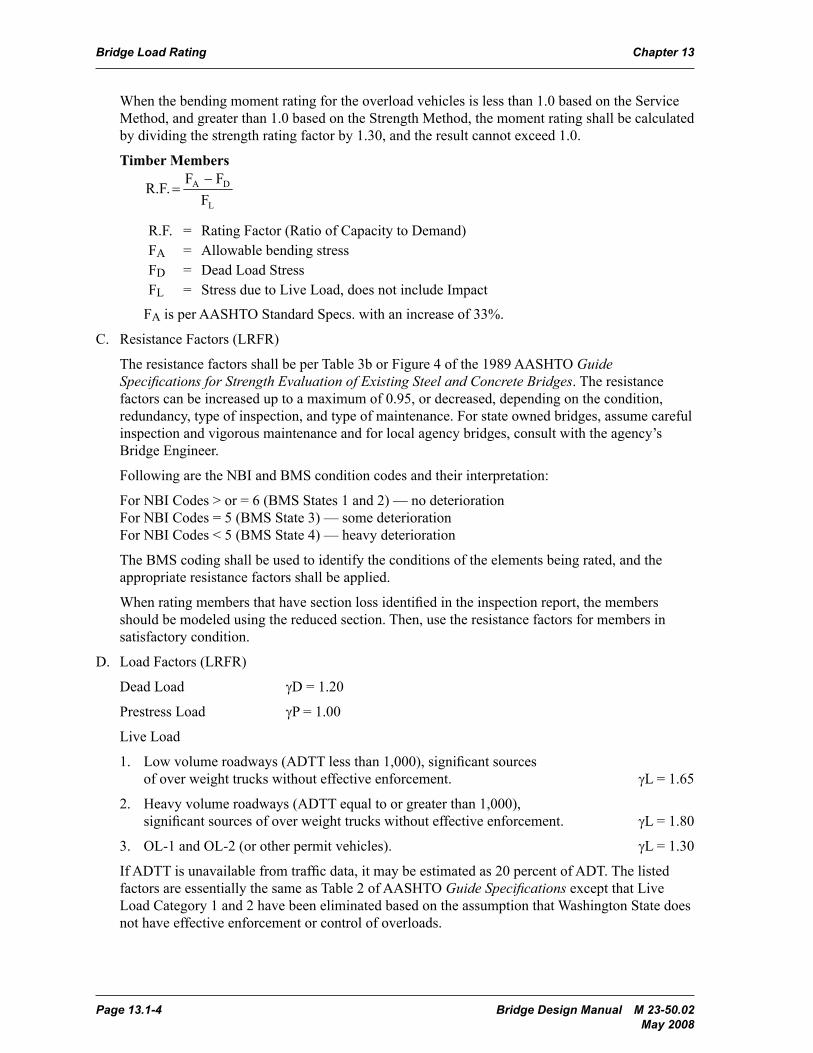
When the bending moment rating for the overload vehicles is less than 1.0 based on the Service Method, and greater than 1.0 based on the Strength Method, the moment rating shall be calculated by dividing the strength rating factor by 1.30, and the result cannot exceed 1.0.
Timber Members
I1LL
PPDLDLn
MγMγMγΦM
R.F.
I1LL
PPDLDLn
VγVγVγΦV
R.F.
I1LL
LoadLegalI1LLPPDLDLn
MγMγMγMγΦM
R.F.
I1LL
LoadLegalI1LLPPDLDLn
VγVγVγVγΦV
R.F.
I1L
A
FF
.R.F
SPD FFF
I1L
A
FF
.R.F
SPD FFF
I1L
21
A
F/F
.R.F
SPD FFF
I1L
A
FF
.R.F
SPD FFF
I1L
DLn
LγSDγΦR
.R.F
L
DA
FFF
.R.F
L12550I
R.F. = Rating Factor (Ratio of Capacity to Demand)FA = Allowable bending stressFD = Dead Load StressFL = Stress due to Live Load, does not include Impact
FA is per AASHTO Standard Specs. with an increase of 33%.
C. Resistance Factors (LRFR)
The resistance factors shall be per Table 3b or Figure 4 of the 1989 AASHTO Guide Specifications for Strength Evaluation of Existing Steel and Concrete Bridges. The resistance factors can be increased up to a maximum of 0.95, or decreased, depending on the condition, redundancy, type of inspection, and type of maintenance. For state owned bridges, assume careful inspection and vigorous maintenance and for local agency bridges, consult with the agency’s Bridge Engineer.
Following are the NBI and BMS condition codes and their interpretation:
For NBI Codes > or = 6 (BMS States 1 and 2) — no deterioration For NBI Codes = 5 (BMS State 3) — some deterioration For NBI Codes < 5 (BMS State 4) — heavy deterioration
The BMS coding shall be used to identify the conditions of the elements being rated, and the appropriate resistance factors shall be applied.
When rating members that have section loss identified in the inspection report, the members should be modeled using the reduced section. Then, use the resistance factors for members in satisfactory condition.
D. Load Factors (LRFR)
Dead Load γD = 1.20
Prestress Load γP = 1.00
Live Load
1. Low volume roadways (ADTT less than 1,000), significant sources of over weight trucks without effective enforcement. γL = 1.65
2. Heavy volume roadways (ADTT equal to or greater than 1,000), significant sources of over weight trucks without effective enforcement. γL = 1.80
3. OL-1 and OL-2 (or other permit vehicles). γL = 1.30
If ADTT is unavailable from traffic data, it may be estimated as 20 percent of ADT. The listed factors are essentially the same as Table 2 of AASHTO Guide Specifications except that Live Load Category 1 and 2 have been eliminated based on the assumption that Washington State does not have effective enforcement or control of overloads.
Bridge Design Manual M 23-50.02 Page 13.1-5 May 2008
Chapter 13 Bridge Load Rating
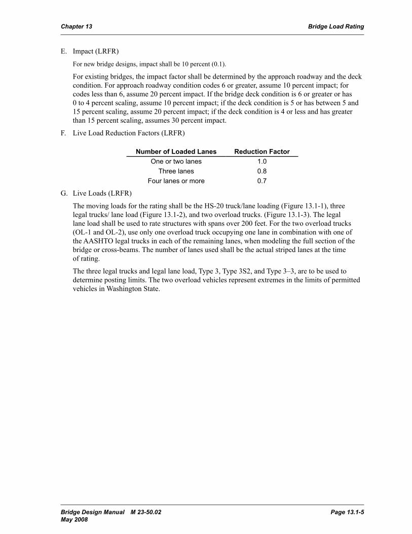
E. Impact (LRFR)
For new bridge designs, impact shall be 10 percent (0.1).
For existing bridges, the impact factor shall be determined by the approach roadway and the deck condition. For approach roadway condition codes 6 or greater, assume 10 percent impact; for codes less than 6, assume 20 percent impact. If the bridge deck condition is 6 or greater or has 0 to 4 percent scaling, assume 10 percent impact; if the deck condition is 5 or has between 5 and 15 percent scaling, assume 20 percent impact; if the deck condition is 4 or less and has greater than 15 percent scaling, assumes 30 percent impact.
F. Live Load Reduction Factors (LRFR)
Number of Loaded Lanes Reduction FactorOne or two lanes 1.0
Three lanes 0.8Four lanes or more 0.7
G. Live Loads (LRFR)
The moving loads for the rating shall be the HS-20 truck/lane loading (Figure 13.1-1), three legal trucks/ lane load (Figure 13.1-2), and two overload trucks. (Figure 13.1-3). The legal lane load shall be used to rate structures with spans over 200 feet. For the two overload trucks (OL-1 and OL-2), use only one overload truck occupying one lane in combination with one of the AASHTO legal trucks in each of the remaining lanes, when modeling the full section of the bridge or cross-beams. The number of lanes used shall be the actual striped lanes at the time of rating.
The three legal trucks and legal lane load, Type 3, Type 3S2, and Type 3–3, are to be used to determine posting limits. The two overload vehicles represent extremes in the limits of permitted vehicles in Washington State.
Page 13.1-6 Bridge Design Manual M 23-50.02 May 2008
Bridge Load Rating Chapter 13
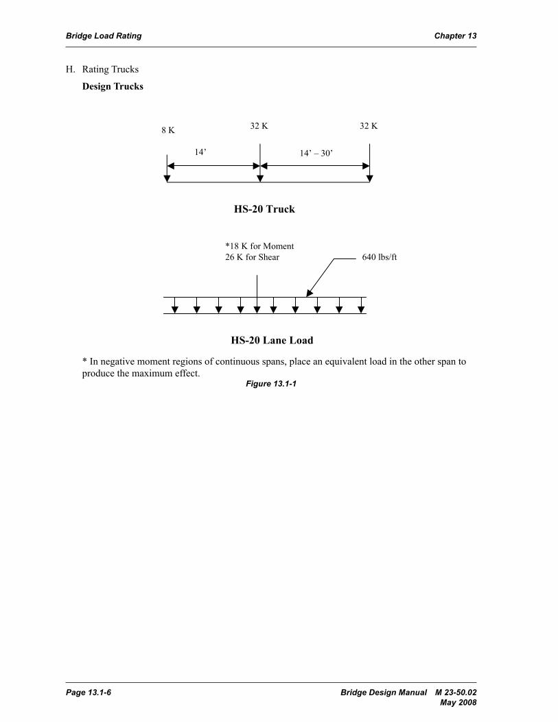
H. Rating Trucks
Design Trucks
The three legal trucks and legal lane load, Type 3, Type 3S2, and Type 3–3, are to be used to determine posting limits. The two overload vehicles represent extremes in the limits of permitted vehicles in Washington State.
13.1.1.8 Rating Trucks
Design Trucks
In negative moment regions of continuous spans, place an equivalent load in the other span to produce the maximum effect.
Figure 13.1.1.8-1
8 K 32 K32 K
14’ 14’ – 30’
HS-20 Truck
*18 K for Moment26 K for Shear
HS-20 Lane Load
640 lbs/ft
* In negative moment regions of continuous spans, place an equivalent load in the other span to produce the maximum effect.
Figure 13.1-1
Bridge Design Manual M 23-50.02 Page 13.1-7 May 2008
Chapter 13 Bridge Load Rating
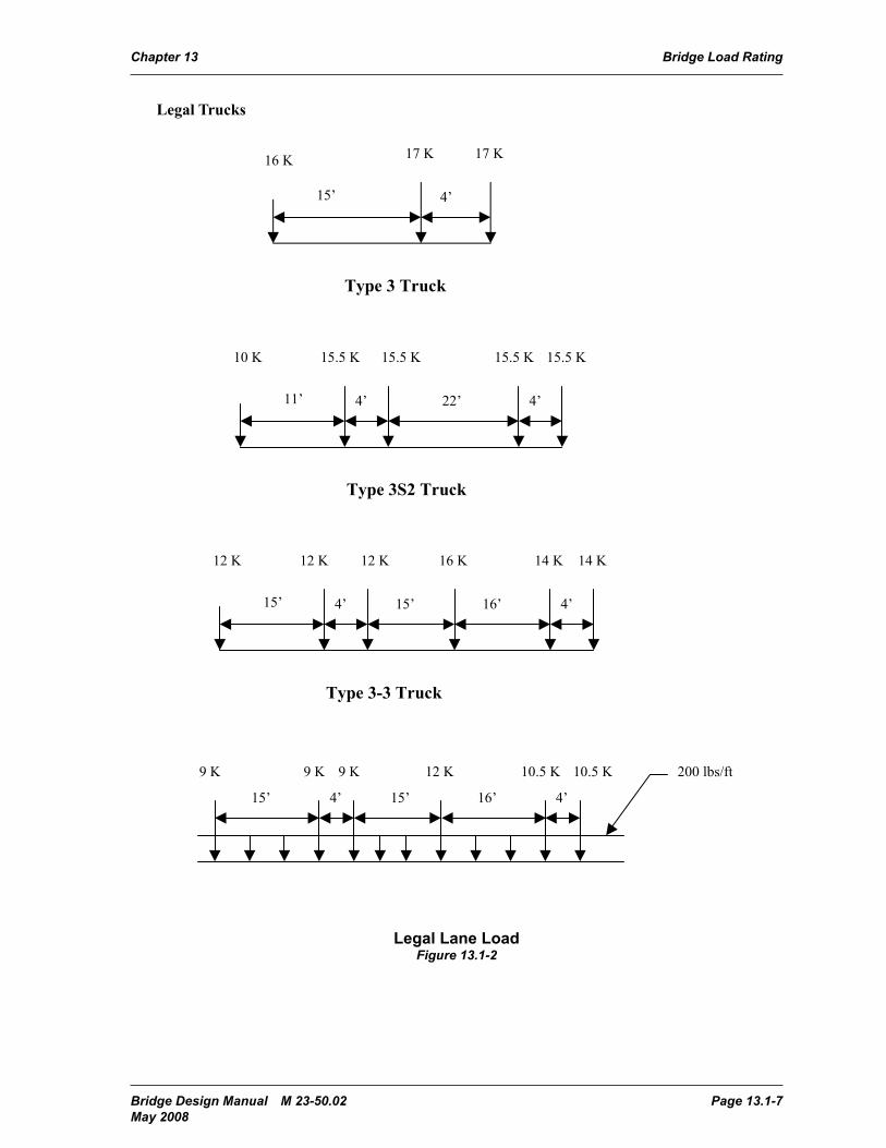
Legal TrucksLegal Trucks
Figure 13.1.1.8-2
16 K 17 K17 K
15’ 4’
Type 3 Truck
10 K 15.5 K15.5 K
11’ 22’
Type 3S2 Truck
4’4’
15.5 K 15.5 K
12 K 14 K12 K
15’ 15’
Type 3-3 Truck
4’4’
12 K 14 K
16’
16 K
9 K
Legal Lane Load
200 lbs/ft9 K 9 K 12 K 10.5 K 10.5 K
15’ 15’4’ 4’16’
Legal Lane LoadFigure 13.1-2
Page 13.1-8 Bridge Design Manual M 23-50.02 May 2008
Bridge Load Rating Chapter 13
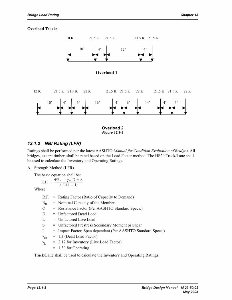
Overload TrucksOverload Trucks
Figure 13.1.1.8-3
10 K 21.5 K21.5 K
10’ 12’
Overload 1
4’4’
21.5 K 21.5 K
12 K 22 K
10’ 16’
Overload 2
14’4’
22 K
4’
21.5 K
4’6’ 6’ 6’
21.5 K 21.5 K21.5 K22 K21.5 K 21.5 K
Overload 2Figure 13.1-3
13.1.2 NBI Rating (LFR)Ratings shall be performed per the latest AASHTO Manual for Condition Evaluation of Bridges. All bridges, except timber, shall be rated based on the Load Factor method. The HS20 Truck/Lane shall be used to calculate the Inventory and Operating Ratings.
A. Strength Method (LFR)
The basic equation shall be:
R.F.L 1 I
R D SL
n DL !=
+
-
ccU^ h
Where:
R.F. = Rating Factor (Ratio of Capacity to Demand)Rn = Nominal Capacity of the MemberΦ = Resistance Factor (Per AASHTO Standard Specs.)D = Unfactored Dead LoadL = Unfactored Live LoadS = Unfactored Prestress Secondary Moment or ShearI = Impact Factor, Span dependant (Per AASHTO Standard Specs.)γDL = 1.3 (Dead Load Factor)γL = 2.17 for Inventory (Live Load Factor)
= 1.30 for Operating
Truck/Lane shall be used to calculate the Inventory and Operating Ratings.

Bridge Design Manual M 23-50.02 Page 13.1-9 May 2008
Chapter 13 Bridge Load Rating
B. Service Method (LFR)
1. Prestressed and Post-tensioned Members
Prestressed and post-tensioned members in positive moment regions, and where post-tensioning is continuous over the supports, shall also be rated based on allowable stresses at service loads. The lowest rating factor between Service and Load Factor methods shall be the governing Inventory rating. The Operating rating shall be based on the load factor method using a Live Load factor of 1.30. Service ratings for the HS20 shall be the same as stated in Section 13.1.1.B, except the impact factor shall be span dependant.
2. Timber Members
I1LL
PPDLDLn
MγMγMγΦM
R.F.
I1LL
PPDLDLn
VγVγVγΦV
R.F.
I1LL
LoadLegalI1LLPPDLDLn
MγMγMγMγΦM
R.F.
I1LL
LoadLegalI1LLPPDLDLn
VγVγVγVγΦV
R.F.
I1L
A
FF
.R.F
SPD FFF
I1L
A
FF
.R.F
SPD FFF
I1L
21
A
F/F
.R.F
SPD FFF
I1L
A
FF
.R.F
SPD FFF
I1L
DLn
LγSDγΦR
.R.F
L
DA
FFF
.R.F
L12550I
R.F. = Rating Factor (Ratio of Capacity to Demand)F
A= Allowable bending stress
FD
= Dead Load StressF
L= Stress due to Live Load, does not include Impact
* FA, for Inventory rating, shall be per AASHTO Standard Specifications. For Operating
Ratings, FA shall be per AASHTO Standard Specifications with a 33% increase in the
allowable stress.
C. Resistance Factors (LFR)
The resistance factors for NBI ratings shall be per the latest AASHTO Standard Specifications. Following are the NBI resistance factors:
Steel Members: 1.00 (Flexure) 1.00 (Shear)
Prestressed Concrete 1.00 (Flexure, Positive moment) 0.90 (Shear)
Post-tensioned, Cast in place: 0.95 (Flexure, Positive moment) 0.90 (Shear)
Reinforced Concrete: 0.90 (Flexure) 0.85 (Shear)
For prestressed and post-tensioned members, where reinforcing steel is used to resist negative moment, the resistance factors for reinforced concrete section shall be used in the ratings.
D. Live Loads
The HS-20 truck or lane shall be used to load rate bridge members. The number of lanes shall be per AASHTO Standard Specifications, Section 3.6. When multiple lanes are considered, apply the appropriate multilane reduction factor given in Section 13.1.2.F. Load distribution methods are discussed under specific bridge types. Do not consider sidewalk live loads in rating analysis.
Page 13.1-10 Bridge Design Manual M 23-50.02 May 2008
Bridge Load Rating Chapter 13
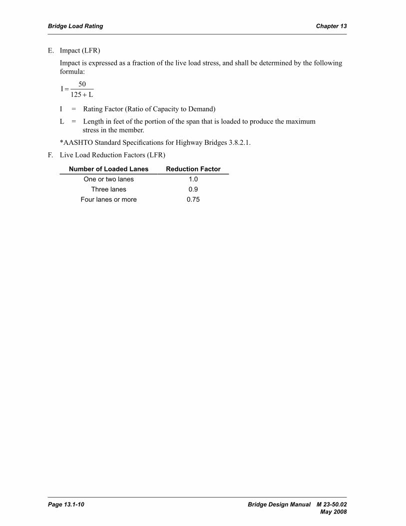
E. Impact (LFR)
Impact is expressed as a fraction of the live load stress, and shall be determined by the following formula:
I1LL
PPDLDLn
MγMγMγΦM
R.F.
I1LL
PPDLDLn
VγVγVγΦV
R.F.
I1LL
LoadLegalI1LLPPDLDLn
MγMγMγMγΦM
R.F.
I1LL
LoadLegalI1LLPPDLDLn
VγVγVγVγΦV
R.F.
I1L
A
FF
.R.F
SPD FFF
I1L
A
FF
.R.F
SPD FFF
I1L
21
A
F/F
.R.F
SPD FFF
I1L
A
FF
.R.F
SPD FFF
I1L
DLn
LγSDγΦR
.R.F
L
DA
FFF
.R.F
L12550I
I = Rating Factor (Ratio of Capacity to Demand)
L = Length in feet of the portion of the span that is loaded to produce the maximum stress in the member.
*AASHTO Standard Specifications for Highway Bridges 3.8.2.1.
F. Live Load Reduction Factors (LFR)
Number of Loaded Lanes Reduction FactorOne or two lanes 1.0
Three lanes 0.9Four lanes or more 0.75
Bridge Design Manual M 23-50.02 Page 13.2-1 May 2008
Chapter 13 Bridge Load Rating
13.2 Special Rating Criteria
13.2.1 Dead LoadsDead Loads shall be as defined in the AASHTO Standard Specifications for Highway Bridges, except concrete weight shall be 155 pcf.
13.2.2 Live Load Distribution FactorsLive Load distribution factors shall be per Chapter 3 of the AASHTO Standard Specifications for Highway Bridges. Distribution factors are selected assuming one traffic lane where the roadway is less than 20 feet wide or two or more traffic lanes where the roadway is 20 feet or wider.
13.2.3 Reinforced Concrete StructuresFor conventional reinforced concrete members of existing bridges, checking of serviceability shall not be part of the rating evaluation.
Rating for shear in the longitudinal direction shall begin at a distance h/2 from the centerline of the bearing or face of integral cross beams (h= total depth).
13.2.4 Concrete DecksFor all concrete bridge decks, except flat slab bridges, that are designed per current AASHTO criteria for HS-20 loading or heavier, loading will be considered structurally sufficient and need not be rated. However, for existing bridge decks having any of the following conditions, rating of the deck is required:
1. Deck was designed for live loads lighter than HS-20.
2. Deck overhang is more than half the girder spacing.
3. Bridge Inspection Report Code is 4 or below.
4. When the original traffic barrier(s) or rail have been replaced by heavier barrier.
When rating of the deck is required, live load shall include all vehicular loads as specified in Section 13.1.1.H. Live load moments for the HS20 truck shall be per Section 3.24.3.1 of the AASHTO Standard Specifications. Live load moments for the legal and overload trucks shall be per the AASHTO Manual for Maintenance Inspection of Bridges.
13.2.5 Concrete CrossbeamsLive loads can be applied to the crossbeam as moving point loads at any location between curbs that produce the maximum effect.
When rating for shear in crossbeams, current AASHTO Design Specifications requires shear design to be at the face of support if there is a concentrated load within a distance “d” from the face of support. This requirement is new relative to earlier editions of AASHTO Design Specifications that allowed shear reinforcement design to be at a distance “d” from the face of support. When rating existing crossbeams that show no indication of distress on the latest inspection report, but have a rating factor of less than one (1.0), a more detailed/accurate shear analysis should be performed. One acceptable method is the “Strut and Tie” model analysis. For existing box girders and T-beams integral with the crossbeams, in lieu of this detailed analysis, dead and live loads can be assumed as uniformly distributed and the shear rating performed at a distance “d” from the face of support.
Page 13.2-2 Bridge Design Manual M 23-50.02 May 2008
Bridge Load Rating Chapter 13
13.2.6 In-Span HingesFor in-span hinges, rating for shear and bending moment should be performed based on the reduced cross-sections at the hinge seat. Diagonal hairpin bars are part of this rating as they provide primary reinforcement through the shear plane.
13.2.7 Concrete Box Girder StructuresBridges with spread box girders shall be rated on a per box basis. Otherwise, the rating shall be on the per bridge basis for all applied loads.
13.2.8 Prestressed Concrete Girder StructuresRate on a per member basis.
13.2.9 Concrete Slab StructuresRate cast-in-place solid slabs on a per foot of width basis. Rate precast panels on a per panel basis. Rate cast-in-place voided slabs based on a width of slab equal to the predominant center-to-center spacing of voids.
When rating flat slabs on concrete piling, assume pin-supports at the slab/pile interface of interior piers and the slab continuous over the supports. If ratings using this assumption are less than 1.0, the piles should be modeled as columns with fixity assumed at 10 feet below the ground surface.
Pile caps are to be rated if deemed critical by the engineer.
13.2.10 Steel StructuresOn existing bridges, checking of fatigue and serviceability shall not be part of the rating evaluation.
13.2.11 Steel Floor SystemsFloorbeams and stringers shall be rated as if they are simply supported. Assume the distance from outside face to outside face of end connections as the lengths for the analysis. Live loads can be applied to the floorbeam as moving point loads at any location between curbs, which produce the maximum effect.
Rating of connections is not required unless there is evidence of deterioration.
13.2.12 Steel Truss StructuresRate on a per truss basis or perform a 3-D analysis or simplified distribution methods. Assume nonredundancy of truss members and pinned connections.
In general, rate chords, diagonals, verticals, end posts, stringers, and floorbeams. Gusset plates and structural pins shall be rated. For pin-connected trusses, analyze pins for shear, and the side plates for bearing capacity.
For truss members that have been heat-straightened three or more times, deduct 0.1 from φ(Phi).
Bridge Design Manual M 23-50.02 Page 13.2-3 May 2008
Chapter 13 Bridge Load Rating
13.2.13 Timber StructuresUnless the species and grade is known, assume Douglas fir, select structural for members installed prior to 1955 and Douglas fir, No. 1 after 1955. The allowable stresses for beams and stringers shall be as listed in the AASHTO Standard Specifications.
The nominal dimensions should be used to calculate dead load, and the net dimensions to calculate section modulus. If the member is charred, it may be assumed that ¼-inch of material is lost on all surfaces. Unless the member is notched or otherwise suspect, shear need not be calculated.
When calculating loads, no impact is assumed.
13.2.14 Widened or Rehabilitated StructuresFor widened bridges, rate crossbeams in all cases.
For existing bridges, a load rating shall be performed if the load carrying capacity of the longitudinal members is altered, or the dead and live loads have increased due to the widening.
Longitudinal rating for the widened portion will be required only when the width of the widened portion on one side of the structure is greater than or equal to 10′-0" or more throughout the length of the structure.
For rehabilitated bridges, a load rating will be required if the load carrying capacity of the structure is altered by the rehabilitation.
13.2.15 A Live Load Factor of 1.45 for ADTT greater than 1000 and 1.30 for ADTT up to 1000 may be applied to bridges which are load rated by the 1989 LRFR method and have reasonable enforcement and apparent control of overloads. Also, the Load Factor method may be used to calculate the rating factors for the three legal loads for some structures. A statement under Note 11 of the Inspection Report shall be added identifying the controlling rating member for structures applying the statements stated above.
The use of the Live Load Factors and Load Factor Method as stated above shall be approved by the *Program Manager as defined by NBIS.
*The Program Manager is the individual in charge of the bridge program that has been assigned or delegated the responsibilities for bridge inspection, reporting, and inventory. The program manager provides overall leadership and is available to inspection team leaders to provide guidance. The State may delegate program manager status to qualified local agency bridge owners.

Page 13.2-4 Bridge Design Manual M 23-50.02 May 2008
Bridge Load Rating Chapter 13
Bridge Design Manual M 23-50.02 Page 13.3-1 May 2008
Chapter 13 Bridge Load Rating
13.3 Load Rating SoftwareRating of State bridges shall be performed using the BRIDG for Windows software, latest version.
For more complex structures such as Steel Curved girders and Arches, different software may be used to analyze the loads after obtaining approval from the Load Rating Engineer.

Page 13.3-2 Bridge Design Manual M 23-50.02 May 2008
Bridge Load Rating Chapter 13
Bridge Design Manual M 23-50.02 Page 13.3-3 May 2008
Chapter 13 Bridge Load Rating
13.4 Load Rating ReportsRating reports shall consist of:
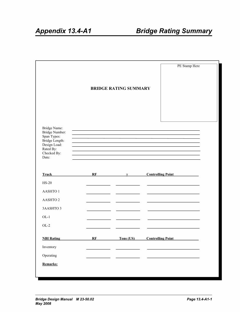
1. A Bridge Rating summary sheet, as shown on Appendix 13.4-A1 reflecting the lowest rating factor, including superstructure components not analyzed by BRIDG, for each loading condition. The summary sheet shall be stamped and signed by a professional engineer licensed in the state of Washington.
2. A brief report of any anomalies in the ratings and an explanation of the cause of any rating factor below 1.0.
3. Hard copy of computer output files (RPT files) used for rating, and any other calculations or special analysis required.
4. A complete set of plans for the bridge.5. One 3.5-inch data diskettes or compact disk which contains the final versions of all input and
output files, and other calculations created in performing the load rating.
All reports shall be bound in Accopress-type binders.
When the load rating calculations are produced as part of a design project (new, widening, or rehabilitation,) the load rating report and design calculations shall be bound separately.
Page 13.3-4 Bridge Design Manual M 23-50.02 May 2008
Bridge Load Rating Chapter 13
Bridge Design Manual M 23-50.02 Page 13.5-1 May 2008
Chapter 13 Bridge Load Rating
13.5 Bibliography 1. AASHTO Guide Specifications For Strength Evaluation of Existing Steel and Concrete
Structures, 1989.
2. AASHTO Manual for Condition Evaluation of Bridges, Second Edition.
3. AASHTO Guide Specifications for Strength Design of Truss Bridges, Load Factor Design, 1985.
4. AASHTO Manual for Maintenance Inspection of Bridges.
5. AASHTO Standard Specifications for Highway Bridges, 17th edition.

Page 13.5-2 Bridge Design Manual M 23-50.02 May 2008
Bridge Load Rating Chapter 13
Bridge Design Manual M 23-50.02 Page 13.4-A1-1 May 2008
Appendix 13.4-A1 Bridge Rating Summary
BRIDGE RATING SUMMARY
Truck RF Controlling Point
NBI Rating RF Tons (US) Controlling Point
Remarks:

Page 13.4-A1-2 Bridge Design Manual M 23-50.02 May 2008
Bridge Load Rating Chapter 13