chapter 12 construction equipment power...
TRANSCRIPT

Chapter 12
Construction Equipment Power Trains Topics
100 Drive Trains
200 Track and Track Frames
300 Winches and Wire Rope
To hear audio click on the box
Overview The construction equipment used by the Navy is equipped with power trains that are similar to those of automobiles which we have already discussed However when we factor in the size weight design and use the construction equipment requires power trains that vary greatly in configuration In this chapter we will discuss the operational characteristics and components of the drive trains track assemblies and track frames that are common to construction equipment Further you will learn the operation of a winch and be able to identify the characteristics and maintenance of wire rope
Objectives When you have completed this chapter you will be able to do the following
1 Identify the operational characteristics and components of construction equipment drive trains
2 Identify the operational characteristics and components of track assemblies and track frames on construction equipment
3 Understand the maintenance procedures used on tracks and track frame assemblies
4 Understand the operation of a winch 5 Identify the characteristics and maintenance of wire rope
NAVEDTRA 14264A 12-1
null
2010-06-23T150651-0500
3320189
Prerequisites This course map shows all of the chapters in Construction Mechanic Basic The suggested training order begins at the bottom and proceeds up Skill levels increase as you advance on the course map
Automotive Chassis and Body C
Brakes M
Construction Equipment Power Trains
Drive Lines Differentials Drive Axles and Power Train Accessories
Automotive Clutches Transmissions and Transaxles
Hydraulic and Pneumatic Systems
Automotive Electrical Circuits and Wiring
B A
Basic Automotive Electricity S
Cooling and Lubrication Systems I
Diesel Fuel Systems C
Gasoline Fuel Systems
Construction of an Internal Combustion Engine
Principles of an Internal Combustion Engine
Technical Administration
Features of this Manual This manual has several features which make it easy to use online
bull Figure and table numbers in the text are italicized The figure or table is either next to or below the text that refers to it
bull The first time a glossary term appears in the text it is bold and italicized When your cursor crosses over that word or phrase a popup box displays with the appropriate definition
bull Audio and video clips are included in the text with italicized instructions telling you where to click to activate it
bull Review questions that apply to a section are listed under the Test Your Knowledge banner at the end of the section Select the answer you choose If the answer is correct you will be taken to the next section heading If the answer is
NAVEDTRA 14264A 12-2
incorrect you will be taken to the area in the chapter where the information is for review When you have completed your review select anywhere in that area to return to the review question Try to answer the question again
bull Review questions are included at the end of this chapter Select the answer you choose If the answer is correct you will be taken to the next question If the answer is incorrect you will be taken to the area in the chapter where the information is for review When you have completed your review select anywhere in that area to return to the review question Try to answer the question again
NAVEDTRA 14264A 12-3
100 DRIVE TRAINS There are numerous types of equipment used in construction from crawler tractors to excavators However the way power is distributed varies from piece to piece The most common drive trains used in modern construction equipment are the mechanical and the hydrostatic drive trains
110 Mechanical Drive Trains The mechanical drive train found in construction equipment is similar to that of the automatic transmission in that a transmission is used in conjunction with a torque converter and shifting is accomplished hydraulically when the operator moves the range selector lever
111 Planetary Gearsets Some power shift transmissions use planetary gearsets to perform the same functions as the transmission just described (Figure 12-1) A planetary gearset consists of three membersmdashsun gear ring gear and a planetary carrier that holds the planetary gears in proper relation with the sun and ring gear The planetary gears are free to walk around the sun gear or inside the ring gear To cause a reduction or increase in torque six different methods of connecting this gearset to the power train are possible Direct drive is achieved by locking any two members together and neutral is obtained by allowing all the gears to turn freely
In actual application planetary gearsets are used as single or multiple units depending on the number of speed (gear) ranges desired On tracked equipment power for turning the drive sprockets may flow through a planetary gear arrangement that provides maximum reduction The sun gear forces the planetary gears to revolve in the stationary ring gear and move the carrier in the same direction of rotation as the sun gear The carrier is connected to the hub on which the sprocket is mounted causing it to rotate with the carrier This arrangement produces the maximum torque and speed reduction obtainable from a planetary gearset
112 Planetary Steering Some tracked equipment may be steered by a system that combines planetary steering and pivot brakes The planetary steering system differs from the one previously described in that the planetary pinion gears are two gears of different sizes machined into one piece (Figure 12-2) Two sun gears are also included One sun gear is splined to the sprocket pinion shaft and the other is machined on the steering brake hub The sun gear machined to the steering brake hub performs the same function as the ring gear in a conventional planetary system Bushings are used to isolate the sprocket drive shafts and the steering brake hubs from the bevel gear carrier and the planetary carrier Lubrication is provided from the oil sump located below the assembly
Figure 12-1 mdash Planetary gearset
NAVEDTRA 14264A 12-4
When the tracked equipment travels straight ahead its steering brakes are held in the applied position by heavy coil springs Braking prevents the steering brake hub and sun gear from rotating and forces the large planetary pinion gears to walk around the sun gear Then power is transmitted to the sun gear on the sprocket drive shaft from the smaller planetary pinion gears When a gradual turn is being made the operator moves one of the steering levers back far enough to release the steering brake on one end of the planetary system When the brake is released the planetary pinion gears stop walking around the sun gear on the steering brake hub This hub then rotates with the planetary carrier and no power is transmitted to the sprocket drive shaft Occasionally an adjustment of the steering brake is required to prevent slippage when it is engaged Consult the manufacturers service manual for adjustment procedures
113 Steering Clutches Steering clutches are used in the clutch-brake system where the output of a single power source drives both tracks directly Since they are physically connected to each other the tracks must turn at the same speed and the vehicle will travel in a straight line To allow for turns each track can be disconnected from the engine with a clutch allowing that track to slow and the vehicle to turn fairly gently A brake allows the disengaged track to be slowed to tighten the turn even to the point of stopping the track
Figure 12-2 mdash Planetary steering system
NAVEDTRA 14264A 12-5
This system is fairly simple and easy to drive however it is not very efficient Braking one track slows the vehicle and wastes a large portion of the power produced by the engine to be converted into heat While this is not a significant problem in a small vehicle a large vehicle with a large engine can produce a tremendous amount of heat in a very short time Braking one track also slows the vehicle down significantly which is a consideration in military vehicles where speed is paramount
120 Hydrostatic Drive Train The hydrostatic drive is an automatic fluid drive that uses fluid under pressure to transmit engine power to the drive wheels or tracks Mechanical power from the engine is converted to hydraulic power by a pump-motor team This power is then converted back to mechanical power for the drive wheels or tracks The pump-motor team is the heart of the hydrostatic drive system Basically the pump and motor are joined in a closed hydraulic loop the return line from the motor is joined directly to the intake of the pump rather than to the reservoir (Figure 12-3) A charge pump maintains system pressure using supply oil from the reservoir The hydrostatic drive functions as both a clutch and transmission The final gear train then can be simplified with the hydrostatic unit supplying infinite speed and torque ranges as well as reverses speeds To understand hydrostatic drive you must understand two principles of hydraulics
bull Liquids have no shape of their own
bull Liquids are not compressible The basic hydrostatic principle is as follows (Figure 12-4)
bull Two cylinders connected by a line are both filled with oil Each cylinder contains a piston
bull When a force is applied to one of the pistons the piston moves against the oil Since the oil will not compress it acts as a solid connection and moves the other piston
In a hydrostatic drive several pistons are used to transmit powermdashone group in the PUMP sending power to another group in the MOTOR The pistons are in a cylinder block and revolve around a shaft The pistons also move in and out of the block parallel to the shaft
Figure 12-3 mdash Hydrostatic pump-motor
Figure 12-4 mdash Hydrostatic principle
NAVEDTRA 14264A 12-6
To provide a pumping action for the pistons a plate called a swash plate is located in both the pump and motor (Figure 12-5) The pistons ride against the swash plates The angle of the swash plates can be varied so the volume and pressure of oil pumped by the pistons can be changed or the direction of the oil reversed A pump or motor with a movable swash plate is called a variable-displacement unit A pump or motor with a fixed swash plate is called a fixed displacement unit There are four pump-motor combinations (Figure 12-6)
bull Fixed displacement pump driving a fixed displacement motor (Figure 12-6 View A) This setup will give you constant horsepower and torque at the output with a steady input speed If input speed varies horsepower and speed will vary but torque will remain constant Because both the pump and motor are fixed displacement this system is like a gear drive it transmits power without altering the speed or horsepower between the engine and the load
Figure 12-5 mdash Hydrostatic principle with swash plates
Figure 12-6 mdash Pump and motor combination for hydrostatic drives
NAVEDTRA 14264A 12-7
bull Variable displacement pump driving a fixed displacement motor (Figure 12-6 View B) Since the pump is variable output speed is variable and torque output is constant for any given pressure This setup provides variable speed and constant torque
bull Fixed displacement pump driving a variable displacement motor (Figure 12-6 View C) In this setup changing the motor displacement varies output speed When motor displacement decreases output speed increases but output torque drops When the setup is balanced it gives a constant horsepower output
bull Variable displacement pump driving a variable displacement motor (Figure 12-6 View D) This setup gives an output of both constant torque and constant horsepower It is the most flexible of all the setups but it is also the most difficult to control
The direction of output shaft rotation can be reversed in variable setups by shifting either the pump or the swash plate of the motor over center Remember three factors control the operation of a hydrostatic drive
bull Rate of oil flowmdashgives the speed
bull Direction of oil flowmdashgives the direction
bull Pressure of the oilmdashgives the power The pump is driven by the engine of the machine and is linked to the speed set by the operator It pumps a constant stream of high-pressure oil to the motor Since the motor is linked to the drive wheels or tracks of the machine it gives the machine its travel speed The advantages of hydrostatic drive are as follows
bull Infinite speeds and torque
bull Easy one-lever control
bull Smooth shifting
bull On the go shifting
bull High torque available for starting up
bull Flexible locationmdashno drive lines
bull Low maintenance and service
bull Reduction of shock loads
bull Compact size
bull Elimination of clutches and large gear trains
121 Hydrostatic Drive Operation So that you will understand how a hydrostatic drive operates we will explain the operation of a typical system The system we will use has an axial piston pump and motor which is the most common hydrostatic drive system The pump has a variable displacement while the motor has a fixed displacement Now look at the complete system in operation forward neutral and reverse
NAVEDTRA 14264A 12-8
1211 Forward (Figure 12-7) When the operator moves the speed control lever forward the spool in the displacement control valve also known as the FNR valve (Forward Neutral and Reverse) moves from its neutral position This action allows pressure oil to flow into the upper servo cylinder forcing the swash plate to tilt Oil expelled by the opposing servo cylinder returns through the displacement control valve (FNR valve) to the pump case
As the swash plate reaches the tilt set by the speed control lever the displacement control valve (FNR valve) spool returns to a neutral position trapping the oil to both servo cylinders and holding the swash plate in its titled position The swash plate will remain titled until the operator moves the speed control lever With the pump drive shaft and cylinder block rotating clockwise and the swash plate titled to the rear it is now time to start pumping As the cylinder rotates past the pump inlet port the inlet check valve opens Oil is then forced by the charge pump into the piston bores that align with the inlet port under low charge pressure As rotation continues oil is forced out of the outlet port at high pressure by the pump pistons when they align with the outlet port This flow of oil drives the motor The distance the pistons reciprocate in and out of the cylinder block depends on the angle of the swash plate of the pump This determines the volume of oil displaced per revolution of the pump--the greater the angle the greater the volume of oil that flows from the pump As the angle of the swash plate is varied so will the volume of oil displaced from the pump
Figure 12-7 mdash Hydrostatic drive operation
NAVEDTRA 14264A 12-9
As pressure oil enters the inlet port of the motor the pistons that align with the inlet port push against the swash plate Since the fixed swash plate is always tilted the pistons slide down the inclined surface and the resulting forces rotate the cylinder block This in turn rotates the output shaft driving the machine forward As the cylinder block continues to rotate clockwise oil is forced out the outlet port at low pressure and returns to the pump where it is recirculated through the pump and back to the motor This is called a ldquoclosed systemrdquo because the oil keeps circulating between the pump and the motor The only extra oil comes from the charge pump that maintains a given flow of oil through the system whenever the machine is running A shuttle valve located in the motor manifold and controlled by high oil pressure prevents high oil pressure from entering the low-pressure side of the system This action keeps the charge circuit open to the low-pressure valve while the system is running The high-pressure relief valve located in the motor manifold monitors the pressure of the forward flow of oil and protects the system from too high pressures If pressure exceeds the rated psi a relief valve opens and oil bypasses the cylinder block in the motor This will either slow or stop the machine The bypassed oil returns to the pump This action continues until the load is reduced below the rated psi Then the relief valve closes and oil again flows to the cylinder block moving the machine forward
1211 Neutral With the speed control lever in neutral free oil flows from the reservoir through the oil filter to the charge pump (Figure 12-7) The charge pump pumps the oil past the high charge pressure control valve and into the main pump housing The oil circulates through the housing and returns through the oil cooler and back to the reservoir Trapped oil is held in the cylinder block of the pump in the motor and in the connecting lines between the pump and motor by two check valves in the pump end cap When the control lever is in neutral the swash plate in the pump is also in neutral and the pistons within the pump are not pumping Therefore no oil is being moved to provide either forward or reverse motion The cylinder block in the pump rotates in a clockwise direction and is driven by the engine of the equipment Rotation is viewed from the drive shaft end of the pump Because the oil is not being pumped to the motor the cylinder block in the motor is stationary and the output shaft does not move
NOTE With the drive system in neutral the high charge pressure control valve (located at the charge pump) controls pump pressure When the system is activated for reverse or forward the low charge pressure control valve located in the motor manifold controls the charge pressure at a lower psi
1211 Reverse (Figure 12-7) As the speed control valve is moved to reverse the spool in the displacement control valve (FNR valve) moves out of neutral allowing pressure oil to flow into the lower servo cylinder and tilting the swash plate forward When the swash plate reaches its desired tilt which is set by the control lever the displacement control spool returns to neutral This action traps the oil to both servo NAVEDTRA 14264A 12-10
cylinders and keeps the swash plate tilted The swash plate will remain in position until the speed control lever is moved again by the operator With the swash plate tilted forward and the pump drive shaft and cylinder block rotating clockwise the ports reverse and the inlet port becomes the outlet and the outlet port becomes the inlet As the pump cylinder block rotates past the pump inlet port a check valve opens and oil is forced by the charge pump into the piston bores that align with the inlet port of the pump As rotation continues the oil is pressurized and forced out of the outlet port of the pump by each of the pistons as they align with the outlet port This action forces oil to flow to the motor and as high-pressure oil from the pump enters the inlet port of the motor the pistons are pushed against the swash plate The pistons slide down the inclined surface of the swash plate rotating the cylinder block This action rotates the drive shaft counterclockwise driving the piece of equipment in reverse As the motor cylinder block continues to rotate oil is forced out the outlet port at low pressure and returns to the pump
NOTE The pump drive shaft and cylinder block always rotate clockwise but the motor drive shaft and cylinder block rotate in clockwise and counterclockwise directions depending on the direction of the oil entering the pump
122 Maintenance of Hydrostatic Drives As with any hydraulic system the hydrostatic drive system is fairly easy to maintain The fluid provides a lubricant and protects against overload Like any other mechanism it must be operated properly too much speed too much heat too much pressure or too much contamination will cause damage
Before removing any part of the system ensure that the area is clean Use steam-cleaning equipment if available however do NOT let any water into the system Ensure that all hose and line connections are tight If steam cleaning is not possible diesel fuel or a suitable solvent may be used Be certain to remove all loose dirt and foreign matter that may contaminate the system Impurities such as dirt lint and chaff cause more damage than any one thing Always seal openings when doing work to prevent foreign matter from entering the system Clean the workbench or table before disassembling any hydrostatic system component for servicing Be sure that all tools are clean and free of dirt and grease
NOTE NEVER perform internal service work on the shop floor or ground or where there is a danger of dust or dirt being blown into the parts Before you disassemble of any system component for internal service certain items must be available including the following
bull Clean plastic plugs of various sizes to seal the openings when removing hydraulic hoses and lines
bull Clean plastic bags to place over the ends of the lines and hoses Secure the bags to the lines and hoses with rubber bands
bull A container of solvent to clean internal parts Ensure that all parts are clean before replacing them You may use compressed air to dry the parts after cleaning
NAVEDTRA 14264A 12-11
bull A container of hydraulic fluid to lubricate the internal parts as they are reassembled
bull A container of petroleum jelly to lubricate surfaces where noted by the manufacturer during reassembly
Anytime you service and reassemble the components always install new O-rings seals and gaskets This provides tight seals for mating parts and eliminates leakage
NOTE For instructions on the disassembly and reassembly of hydrostatic components refer to the manufacturerrsquos service manual Never operate the hydraulic system empty Always check the fluid supply after servicing the system If fluid is to be added to the system use ONLY the fluid recommended in the service manual
Test your Knowledge (Select the Correct Response)1 What are the two most commont types of drive trains used in modern
construction equipment
A Mechanical and hydromechanical B Pneumatic and mechanical C Hydrostatic and mechanical D Pneumatic and hydrostatic
200 TRACK and TRACK FRAMES The undercarriage of crawler-mounted equipment contains two major componentsmdashTrack Assembly and Track Frame This undercarriage is provided on equipment that must have positive traction to operate efficiently (Figure 12-8)
210 Track Assembly The track assembly consists of a continuous chain surrounding the track frame and drive sprocket The links of the chain provide a flat surface for the track rollers to pass over as they support the equipment Track shoes are bolted to the outside links of the chain and distribute the weight of the equipment over a large surface area
Figure 12-8 mdash Side view of a crawler tractor chassis
NAVEDTRA 14264A 12-12
211 Track Chain Figure 12-9 shows a cutaway view of a section of track chain showing the internal arrangement of the pins and bushings As the tractor operates the drive sprocket teeth contact the track pin bushings and propel the tractor along the track assembly The pins and bushings wear much faster than other parts of the track because of their constant pivoting as the track rotates around the track frame This pivoting results in internal wear of both the pin and the bushing As the pins and bushings wear the track lengthens When it does the track is adjusted to remove excessive slack Bushings that show lots of wear on the outside are good indicators of inner wear that is also nearing the maximum allowed by the manufacturer if the track is to be rebuilt To determine whether the track should be removed for rebuilding or replacement measure the outside of the bushings and track pitch (length of the track) Use an outside caliper and ruler as shown in Figure 12-10 Measure the outside of the bushing where it shows the most wear and compare it to the manufacturerrsquos specifications Measure track pitch with a ruler or tape measure across four track pins after tightening the track to remove any slack as shown in Figure 12-11 Should the bushing wear or track length be excessive remove the track for rebuilding unless facilities and time do not permit Rebuilding a track will nearly double the useful life of the pin and bushings
Figure 12-9 mdash Cutaway view of a section of a track chain
Figure 12-10 mdash Bushing wear measurement
Figure 12-11 mdash Track pitch measurement
NAVEDTRA 14264A 12-13
212 Track Shoes The most common track shoe is the grouser shoe shown in Figure 12-12 This shoe is standard on all crawler-mounted dozers The extreme service track shoe is equipped on crawler-mounted dozers that operate primarily in rocky locations such as rock quarries and coral beaches (Figure 12-13 View A) Notice the grouser or raised portion of the shoe is heavier than on the standard grouser shoe
Another shoe common to track-mounted front-end loaders is the multipurpose shoe (Figure 12-13 View B) This shoe has three grousers that extend a short distance above the shoe and are equally spaced across its face The multipurpose shoe allows more maneuverability with less wear on the track and track frame components
NOTE The grouser absorbs most of the wear and its condition indicates when the track needs replacement or overhaul
220 Track Frame The track frame as the name implies serves as a framework and support for the track assembly rollers front idler recoil spring and adjusting mechanism Track frame alignment may be fixed or shim adjusted depending on the manufacturer When shims are used there are a couple of ways alignment may be maintained One way is using shims where the frame attaches to the rear pivot and also near the center of the track frame where it is mounted against the main frame guide brackets Another way is to use a diagonal brace and shims at the rear pivot to align the track frame
221 Track Frame Rollers Two types of track frame rollers are used on tracked equipmentmdashthose located on the lower portion of the track frame which supports the weight of the tractor and those above the track frame which supports the track assembly as it passes over the track frame
Figure 12-12 mdash Standard grouser shoe
Figure 12-13 mdash Extreme service track shoe
NAVEDTRA 14264A 12-14
Carrier rollers are single-flanged rollers mounted on brackets which extend above the track frame and support the track assembly (Figure 12-14) Two of these rollers are on each side of the tractor The flange extends upward between the links of the track chain keeping the chain in alignment between the drive sprocket and the front idler
Track rollers are double- and single-flanged rollers that support the weight of the tractor ensure that the track chain is aligned with the track frame as it passes under the rollers and prevent side-to-side track movement and derailment (Figure 12-15) In a normal arrangement a double-flanged roller is directly in front of the drive sprocket followed by a single-flanged roller The rollers alternate forward to the front idler The front idler as shown in Figure 12-15 serves as a guiding support for the track chain The idler is spring-loaded and mounted on slides or guides that allow it to move back and forth inside the track frame as the tractor passes over uneven terrain The spring loading effect causes the idler to maintain the desired tension regardless of operating conditions
222 Recoil Spring The recoil spring is a large coil spring placed in the track frame in a way that enables the spring to absorb shock from the front idler The spring is compressed before installation and held in place by stops or spacers The track adjusting mechanism by pressing against the spring stop maintains the desired tension on the track assembly by holding the idler and yoke in a forward position The operation of the recoil springs depends on the amount of tension on the track
223 Adjusting Mechanism The adjusting mechanism (Figure 12-8) must be extended enough to remove slack between the front idler and spring This adjustment may be made by either manual or hydraulic means Many older tractors have manual adjustments whereas newer tractors are adjusted hydraulically with a grease gun Grease is pumped into the yoke cylinder and extends it until enough tension is placed on the recoil spring to remove the slack from the track Tension is released by loosening the vent screw located next to the adjustment fitting
Figure 12-14 mdash Track carrier rollers
Figure 12-15 mdash Track rollers in the track frame
NAVEDTRA 14264A 12-15
NOTE Do NOT lubricate the adjustment fitting when performing maintenance on the tractor
224 Track Guiding Guards Accumulation of rock and dirt packed in the track causes the tracks to tighten resulting in additional wear and stress on track components The use of track guiding guards minimizes these sources of possible depreciation Another function of the track guiding guards is maintaining proper track alignment this is considered secondary but actually is the most important function Guiding guards should be repaired when damaged since a damaged guard is worthless as far as protection for track components or assisting in maintaining track alignment When installing new tracks on a piece of equipment check the condition of the guards These guards should be in a condition to guide the track squarely into alignment with the rollers properly The three guards are as follows
bull Front Guiding Guards receive the track from the idler and hold it in line for the first roller The front roller then can be fully utilized for its intended purpose carrying its share of the load without having to climb the side of an improperly aligned track
bull Rear Guiding Guards hold the track in correct alignment with the driving sprocket permitting a smooth even power flow from the sprocket to the track With proper alignment gouging of the track link and sprocket teeth is eliminated
bull Center Guiding Guards or track roller guards are available as attachments These center guards keep the track in line between the rollers when operating in rocky steep or uneven terrain The center guards reduce the wear on roller flanges and track links
230 Maintenance of Track and Track Frame Assemblies Some maintenance of track and track frames is performed at the jobsite by the field maintenance crew This maintenance consists of track adjustment lubrication based on hours as required by the manufacturer and inspection of the track and track frame components
231 Track Adjustment If the tracks are adjusted too tightly there will be too much friction between the pins and bushings when the track links swivel as they travel around the sprocket and front idler This friction causes the pins bushings links sprocket and idler to wear rapidly Friction in a tight track also robs the tractor of needed horsepower Tracks that are too loose fail to stay aligned and tend to come off when the tractor is turned As a result the idler flanges roller flanges and the sides of the sprocket teeth wear down A loose track will whip at high tractor ground speed damaging the carrier rollers and their supports If loose enough the drive sprockets will jump teeth (slide over track bushings) when the tractor moves in reverse Should this happen the sprocket and bushings will wear rapidly One method for determining proper track tension is placing a straightedge over the front carrier roller and idler with all the slack removed from the rest of the track Using a ruler measure from the top of the track shoe to the bottom edge of the straightedge For the correct measurement refer to the manufacturerrsquos manual
NAVEDTRA 14264A 12-16
If it becomes necessary to adjust the track in the field the following method can be used Remove all slack from the track With all slack removed release the pressure until the front idler moves back 12 inch This will provide the required slack in the track until the tractor can be readjusted to the manufacturerrsquos specifications
NOTE Always check the manufacturers maintenance manual for the proper procedures when adjusting tracks
232 Lubrication The track pins and bushing are hardened and require no lubrication Many rollers and idlers are equipped with lifetime seals that are factory lubricated and sealed However track rollers carrier rollers and idlers equipped with grease fittings must be lubricated on a scheduled basis that is set by the manufacturer
NOTE Use ONLY a hand-operated grease gun on these fittings and pump only until resistance is felt Further pumping will damage the seals
233 Inspection When performing routine maintenance inspect the complete track and undercarriage for signs of abnormal wear leaking rollers or idlers and misaligned loose or missing parts Should you find any loose track shoes you should check the torque on all the shoe bolts Any bolts not meeting specifications should be retightened to the prescribed torque If the track appears to be out of alignment report this to your supervisor who will determine what action is required Leaking roller and idler seals should be replaced as soon as possible to prevent any further damage to the equipment
234 Shop Repairs Repairs made to tracks and track frames in the maintenance shop are usually limited to replacing roller or idler seals and bearings or repairing a hydraulic track adjuster On occasion you may find a roller or track that is badly worn and requires replacement
NOTE NEVER replace components of the track or track frame without consulting the wear limitation charts in the manufacturerrsquos service manual
2341 Track Removal Steps for the removal of the track are as follows (Figure 12-16) 1 Release track tension either by manually backing off the track adjuster or by
loosening the vent screw on the hydraulic track adjuster 2 Remove the master pin The master pin can be identified by a locking device or
hole drilled in its end that distinguishes it from the other pins in the chain Move the tractor backward slowly or on some models forward to bring the master pin just below the level of the drawbar Place a block under the grouser on a shoe that allows the master pin to be centered on the front idler With the master pin centered on the front idler remove any locking device If the master pin has a locking device the pin can be removed by using a sledgehammer and a soft
NAVEDTRA 14264A 12-17
metal drift pin Should the pin be drilled a portable press must be used to remove the pin Do not lose the bushings which may drop out with the pin
3 Remove the track from the carrier rollers and idler Slowly move the tractor forward or backward away from the loose ends of the track Make sure no one is in the way of the tractor or the loose end of the track when it falls off the sprocket or front idler
4 Move the tractor off the track Place a plank at the rear of the track The plank should be about the same thickness as the track yet narrow enough to fit between the track frame and guards and long enough so that the entire tractor can rest on the plank
NOTE After removing the tracks always see that the tractor is securely blocked while repairs are being performed Anytime a track is removed thoroughly inspect the track frame components for excessive wear and misalignment Removal disassembly and replacement vary by model and manufacturer Consult the manufacturerrsquos service manual for exact procedures
2342 Track Replacement To replace the tracks back the tractor off the plank and onto the new tracks so the drive sprocket properly meshes with the track rail Continue backing until the tractor is just ahead of the rear end of the track Then place a bar in the track and help the track climb over the sprocket carrier rollers and idler as the tractor is driven forward (Figure 12-17) When the track comes together install the master pin and any locking device Once the track is together adjust the track tension using the manufacturerrsquos recommended procedures
Figure 12-16 mdash Removing tracks
Figure 12-17 mdash Pulling track over the sprocket NAVEDTRA 14264A 12-18
Test your Knowledge (Select the Correct Response)2 How many track links should you measure across when checking track pitch
A Five B Four C Three D Two
300 WINCHES and WIRE ROPE Using a winch and some type of rigging a vehicle can pull itself or another vehicle through such obstacles as muddy or rough terrain This is the primary reason for providing winches on military vehicles In the Naval Construction Force (NCF) an in depth management program for maintenance and use of all rigging gear is required to ensure all operations are performed safely and professionally
310 Winches Most winches that you will encounter are used on tactical vehicles and construction equipment On tactical equipment the winch is mounted behind the front bumper and is secured to the front cross member of the frame or between the two side frame rails In some cases it may be mounted behind the cab of the vehicle The typical front-mounted winch is a jaw-clutch worm-gear type (Figure 12-18)
The jaw-clutch winch consists of a worm gear that is keyed to a shaft A bushed drum is mounted on the worm-gear shaft which is controlled by a hand operated sliding clutch The worm shaft is driven by power from the power takeoff through a solid drive shaft and universal joints The universal joint yoke connected to the worm shaft of the winch has a provision for a shear pin that is made of mild steel This pin has a predetermined breaking strength that allows it to shear when the winch is overloaded
Figure 12-18 mdash Jaw-clutch worm-gear winch
NAVEDTRA 14264A 12-19
A hand-operated sliding clutch is keyed to the worm-gear shaft outside of the winch drum and must be engaged with the jaws on the side of the winch drum when the winch is to be operated Disengagement of the sliding clutch permits the drum to turn on the worm-gear shaft The two brakes that provide control of the winch drum are as follows The Worm Brake Shaft prevents the winch drum from rotating under load when the power takeoff is disengaged The Shifter Bracket Brake prevents the drum from overrunning the cable when the cable is being unreeled Some winches may be equipped with an automatic level-winding device to spool the cable on the drum in tight even coils and layers This prevents crushing of the cable due to loose crossed coils and layers and it allows off leads of the cable while maintaining level winding A broken shear pin usually causes faulty operation of winches Internal damage of the winch can be caused by the use of a shear pin that has too high a breaking strength Internal winch failure resulting from overload is commonly found to be sheared keys or a broken worm shaft Often when the cable is wound unevenly under tension the winch housing will be cracked or broken This will require replacement of the assembly
NOTE NEVER install a shear pin that is not of the proper shearing strength Damage to the winch will occur when overloaded
The winch that you will most likely encounter on construction equipment is the one attached to the rear of a crawler tractor also known as a dozer It is mounted on the rear of the dozer and is directly geared to the rear power takeoff (Figure 12-19) This arrangement permits development of a line of pull that is 50 to 100 percent greater than straight dozer pull The winch is used for uprooting trees and stumps hoisting and skidding stress freeing mired equipment and supporting amphibious construction operations When performing maintenance on a winch ensure that the gear case has the recommended amount and type of lubricant Should disassemble of the winch be required for repairs follow the procedures given in the manufacturers manual
320 Wire Rope Many of the movable components on cranes and attachments are moved by wire rope Wire rope is a complex machine composed of a number of precise moving parts The moving parts of wire rope are designed and manufactured to bear a definite relationship to one another to have the necessary flexibility during operation
Figure 12-19 mdash Winch attachment on a dozer
NAVEDTRA 14264A 12-20
Wire rope may be manufactured by either of two methods If the strands or wires are shaped to conform to the curvature of the finished rope before laying up the rope is termed Preformed Wire Rope If they are not shaped before fabrication the wire rope is termed Non-Preformed Wire Rope The most common type of manufactured wire rope is preformed When cut the wire rope tends not to unlay and is more flexible than non-preformed wire rope With nonpreformed wire rope twisting produces a stress in the wires therefore when it is cut or broken the stress causes the strands to unlay
WARNING When the wire is cut or broken the almost instantaneous unlaying of the wire or strands of the non-preformed wire rope can cause serious injury This situation is apt to occur especially to someone who is careless or not familiar with this characteristic of the rope
321 Composition of Wire Rope Wire rope is composed of three parts wires strands and core (Figure 12-20) A predetermined number of wires of the same or different size are fabricated in a uniform arrangement of definite lay to form a strand The required number of strands are then laid together symmetrically around the core to form the wire rope
3211 Wire Wire rope varies in size and can consist of steel iron or other metals The number of wires to a strand varies depending on the intended purpose of the rope Wire rope is designated by the number of strands per rope and the number of wires per strand Thus a one-half inch 6 x 19 rope has six strands with 19 wires per strand It has the same outside diameter as a one-half inch 6 x 37 rope that has six strands with 37 wires (of smaller size) per strand
3212 Strand The design arrangement of a strand is called the construction The wires in the strand may be all the same size or a combination of different sizes Figure 12-21 show some of the more typical wire rope constructions The most common strand constructions you may encounter are as follows
bull Ordinary construction Wires are all the same size
bull Seale construction Each strand consists of three rings of wire The first ring of wires around the center wire of the strand is of smaller diameter than the center and outer layers Large diameter wires resist abrasion while smaller diameter wires provide flexibility
bull Warrington construction Each strand has two layers of wire about a center wire The outer layer consists of wires that are alternately large and small This alternating wire size combines flexibility with abrasion resistance
Figure 12-20 ndash Parts of a wire rope
NAVEDTRA 14264A 12-21
bull Filler construction Filler wire has small wires filling the voids between the rings of wire in the strand These small wires are not counted when designating the number of wires in the strand This construction type provides abrasion and fatigue resistance
bull Flattened construction Strands are somewhat triangular in shape and sometimes formed around a triangular center wire
3213 Core The wire rope core supports the strands laid around it There are three types of wire rope cores
bull Fiber core consists of a hard fiber such as manila hemp plastic paper or sisal The fiber core offers the advantage of increased flexibility It also serves as a cushion to reduce the effects of sudden strain and acts as an oil reservoir to lubricate the wire and strands (to reduce friction) Wire rope with a fiber core is used when flexibility of the rope is especially important
bull Wire strand core resists more heat than a fiber core and also adds about 15 percent to the strength of the rope However the
Figure 12-21 mdash Common strand construction
Figure 12-22 mdash Core construction NAVEDTRA 14264A 12-22
wire strand core makes the wire less flexible than a rope with a fiber core bull Independent wire rope core (IWRC) is a separate wire rope over which the
main strands of the rope are laid This core strengthens the rope provides support against crushing and supplies maximum resistance to heat Refer to Figure 12-22
322 Grades of Wire Rope
There are four primary grades of wire rope
bull Mild plow steel
bull Plow steel
bull Improved plow steel
bull Extra improved plow steel
3221 Mild Plow Steel Wire Rope Mild plow steel wire rope is tough and pliable It can stand repeated strain and stress and has a tensile strength (resistance to lengthwise stress) of from 200000 to 220000 pounds per square inch (psi) These characteristics make it desirable for cable tool drilling and other uses in which abrasion occurs
3222 Plow Steel Wire Rope Plow steel wire rope is unusually tough and strong This steel which got its name from the original high-carbon crucible furnace steel used to produce plowshares has a tensile strength of 220000 to 240000 psi Plow steel wire rope is suitable for hauling hoisting and logging
3223 Improved Plow Steel Wire Rope Improved plow steel (IPS) wire rope is one of the best grades of rope available and is the wire rope most commonly used in the NCF This type of rope is stronger tougher and more resistant to wear than either mild plow steel or plow steel Each square inch of IPS can stand a strain of 240000 to 260000 pounds This makes it especially useful for heavy-duty service such as on cranes with excavating and weight-handling attachments
3224 Extra Improved Plow Steel Wire Rope Extra improved plow steel (EIP) is 15 stronger than IPS Various manufacturers have their own name for this grade It was developed for applications needing greater safety factors without a diameter increase such as rotary oil-well drilling and for maximum resistance to abrasive wear such as that resulting from draglines in strip mining through rocky terrain This premium grade has tensile strength ranging from 280000 to 340000 psi
NAVEDTRA 14264A 12-23
323 Lays of Wire Rope The term lay refers to the direction of the twist of the wires in a strand and to the direction that the strands are laid in the rope In some instances both the wires in the strand and the strands in the rope are laid in the same direction while in other instances the wires are laid in one direction and the strands are laid in the opposite direction depending on the intended use of the rope Most manufacturers specify the types and lays of wire rope to be used on their piece of equipment Be sure and consult the operators manual for proper application
There are five types of lays used in wire rope (Figure 12-23)
3231 Right Regular Lay The wires in the strands are laid to the left while the strands are laid to the right to form the wire rope
3232 Left Regular Lay The wires in the strands are laid to the right while the strands are laid to the left to form the wire rope In this lay each step of fabrication is exactly opposite from the right regular lay
3233 Right Lang Lay The wires in the strands and the strands in the rope are laid in the same direction in this instance the lay is to the right
3234 Left Lang Lay The wires in the strands and the strands in the rope are also laid in the same direction in this instance the lay is to the left
3235 Reverse Lay The wires in one strand are laid to the right the wires in the nearby strand are laid to the left the wires in the next strand are to the right and so forth with alternate directions from one strand to the other Then all the strands are laid to the right
3236 Lay length of Wire Rope The length of a rope lay is the distance measured parallel to the center line of a wire rope in which a strand makes one complete spiral (or turn) around the rope The length of a strand lay is the distance measured parallel to the center line of the strand in which one wire makes one complete spiral turn around the strand Lay length measurement is shown in Figure 12-24
Figure 12-23 mdash Lay of wire rope
NAVEDTRA 14264A 12-24
324 Characteristics of Wire Rope The NCF use several types of wire typically those with 6 7 12 19 24 or 37 wires in each strand Usually the wire rope has six strands laid around the core The two most common types of wire rope are 6 x 19 and 6 x 37 (Figures 12-25 and 12-26) The 6 x 19 type which has 6 strands with 19 wires in each strand is the stiffest and strongest construction of the wire rope and the most suitable for general hoisting operations The 6 x 37 wire rope six strands with 37 wires in each strand is very flexible making it most suitable for cranes and other pieces of equipment in which sheaves are smaller than usual The wires in the 6 x 37 are smaller than the wires in the 6 x 19 and consequently do not stand as much abrasive wear Consider several factors when selecting a wire rope for use in a particular kind of operation There is not a wire rope in existence that equally withstands all kind of wear and stress Because of this selecting a rope is often a matter of compromise sacrificing one quality to have another more critical characteristic
3241 Tensile Strength Tensile strength is the strength necessary to withstand a certain maximum load applied to the rope It includes a reserve of strength measured in a so-called factor of safety
Figure 12-24 ndash Lay length of wire rope
Figures 12-25 ndash 6 x 19 wire ropes Figure 12-26 ndash 6 x 37 wire rope
NAVEDTRA 14264A 12-25
3242 Crushing Strength Crushing strength is the strength necessary to resist the compressive and squeezing forces that distort the cross section of a wire rope as it runs over sheaves rollers and hoist drums when under a heavy load Regular lay rope distorts less in these situations than lang lay
3243 Fatigue Resistance Fatigue resistance is the ability to withstand the constant bending and flexing of wire rope that runs continuously on sheaves and hoist drums Fatigue resistance is important when the wire rope must run at high speeds Such constant and rapid bending of the rope can break individual wires in the strands Lang lay ropes are best for service requiring high fatigue resistance Ropes with smaller wires around the outside of their strands also have greater fatigue resistance since these strands are more flexible
3244 Abrasion Resistance Abrasion resistance is the ability to withstand the gradual wearing away of the outer metal as the rope runs across sheaves and hoist drums The rate of abrasion depends mainly on the load carried by the rope and its running speed Generally abrasion resistance in a rope depends on the type of metal of which the rope is made and the size of the individual outer wires Wire rope made of the harder steels such as improved plow steel has considerable resistance to abrasion Ropes that have larger wires forming the outside of their strands are more resistant to wear than ropes having smaller wires which wear away more quickly
3245 Corrosion Resistance Corrosion resistance is the ability to withstand the dissolution of the wire metal that results from chemical attack by moisture in the atmosphere or elsewhere in the working environment Ropes such as guy wires that are put to static work may be protected from corrosive elements by paint or other special dressings Wire rope may also be galvanized for corrosion protection Most wire ropes used in crane operations must rely on their lubricating dressing to double as a corrosion preventative
325 Measuring Wire Rope Wire rope is designated by its diameter in inches as shown in Figure 12-27 The correct method of measuring the wire rope is to measure from the top of one strand to the top of the strand directly opposite it Measuring across two side by side strands is not correct To ensure an accurate
Figure 12-27 mdash Correct and incorrect methods of measuring wire rope
NAVEDTRA 14264A 12-26
measurement of the wire ropersquos diameter always measure the rope at three places at least five feet apart Use the average of the three measurements as the diameter of the rope
326 Wire Rope Safe Working Load The safe working load (SWL) of wire rope is the load that can be applied and still obtain the most efficient service and prolong the life of the rope The formula for computing the SWL of a wire rope is the diameter of the rope squared multiplied by 8 (D x D x 8 = SWL in tons) Example The wire rope is 12 inch in diameter Compute the SWL for the rope The first step is to convert the 12 into a decimal number by dividing the bottom number of the fraction into the top number of the fraction (1 divided by 2 = 5) Next compute the SWL formula (5 x 5 x 8 = 2 tons) The SWL of the 12 inch wire rope is 2 tons
NOTE Do NOT downgrade the SWL of wire rope if it is old worn or in poor condition Cut up and discard wire rope in these conditions
327 Wire Rope Failure Some of the common causes of wire rope failure are the following
bull Using incorrect size construction or grade
bull Dragging over obstacles
bull Lubricating improperly
bull Operating over sheaves and drums of inadequate size
bull Overriding or cross winding on drums
bull Operating over sheaves and drums with improperly fitted grooves or broken flanges
bull Jumping of sheaves
bull Exposing to acid or corrosive liquid or gases
bull Using an improperly attached fitting
bull Allowing grit to penetrate between the strands promoting internal wear
bull Subjecting to severe or continuing overload
bull Using an excessive fleet angle
328 Handling and Care of Wire Rope To maximize the safe dependable service of wire rope take care to perform the maintenance necessary to keep the wire rope in good condition Various ways of caring for and handling wire rope are discussed below
NAVEDTRA 14264A 12-27
3281 Coiling and Uncoiling Once a new reel is open it may be coiled or faked down (laid in a coil or series of long loops to allow the rope to run freely without kinking) like line For left lay wire rope coil counterclockwise For right lay wire rope coil clockwise Because of the resilience of the wire it can be resistant to being coiled down When this occurs it is not useful to force the wire down the turn because it will just spring up again Instead throw the wire in a back turn (Figure 12-28) and it will lie down properly A wire rope when faked down runs right off But when wire rope is wound in a coil it has to be unwound manually Wire rope tends to kink during uncoiling or unreeling especially if it has been in use for a long time A kink can cause a weak spot in the rope that wears out more quickly than the rest of the rope A good method for unreeling wire rope is to run a pipe or rod through the center and mount the reel on drum jacks or other supports so the reel is off the ground In this position the reel turns as the rope unwinds and the rotation of the reel helps keep the rope strait During unreeling pull the rope strait forward and try not to rush To avoid kinking NEVER unreel wire rope from a stationary reel Refer to Figure 12-29 To uncoil a small twist of wire rope simply stand the coil on edge and roll it along the ground like a wheel or hoop Do not lay the coil flat on the floorground and uncoil it by pulling on the end-such practice can kink andor twist the rope
3282 Kinks One of the most common forms of damage resulting from improper handling of wire rope is kink development A kink starts with the formation of a loop A loop that has not yet been pulled tight enough to set the wires or strands of the rope into a kink can be removed by turning the rope at either end in the direction appropriate to restore the lay (Figure 12-30) If you attempt to remove a loop simply by pulling it tight a kink will result and the rope will be irreparably damaged Kinking is preventable through proper uncoiling and unreeling methods and by handling the rope correctly at all times
Figure 12-29 mdash Unreeling wire rope and uncoiling wire rope
Figure 12-28 ndash Throwing a back turn
NAVEDTRA 14264A 12-28
3283 Drum Winding Spooling wire rope on a crane hoist drum causes a slight rotating tendency due to the spiral lay of the strands Two types of hoist drums are used for spooling wire rope
bull Grooved drum On grooved drums the grooves generally give sufficient control to wind the wire rope properly whether it is right or left lay rope
bull Smooth-Faced Drum On smooth-faced drums the only influence on the wire rope in winding the first layer is the fleet angle The slight rotational tendency of the rope can be used as an advantage in keeping the winding tight and uniform
NOTE Using the wrong type of wire rope lay causes the rotational tendency of the rope to be a disadvantage because it results in loose and non-uniform rope winding on the hoist drum Figure 12-31 shows drum winding diagrams for selection of the proper lay of rope If you are standing behind the hoist drum and looking toward an oncoming overwind rope the rotating tendency of right lay rope is toward the left whereas the rotating tendency of a left lay rope is toward the right Refer to Figure 12-31 With overwind reeving and a right lay rope on a smooth-faced drum the wire rope bitter end attachment to the drum flange should be at the left flange With underwind reeving and a right lay rope the wire rope bitter end (the end of a rope that is tied off) attachment should be at the right flange When wire rope is run off one reel onto another or onto a winch or drum it should be run from TOP TO TOP or from BOTTOM TO BOTTOM (Figure 12-32)
Figure 12-30 ndash Removing a loop
NAVEDTRA 14264A 12-29
Figure 12-31 mdash Different lays of wire rope winding on hoist drums
Figure 12-32 mdash Transferring wire rope from reel to drum
NAVEDTRA 14264A 12-30
3284 Fleet Angle The fleet angle is formed by running wire rope between a sheave and a hoist drum whose axles are parallel to each other (Figure 12-33) Too large a fleet angle can cause the wire rope to climb the flange of the sheave and can also cause the wire rope to climb over itself on the hoist drum
3285 Sizes of Sheaves The diameter of a sheave should never be less than 20 times the diameter of the wire rope An exception is 6 x 37 wire for which a smaller sheave can be used because this wire rope is more flexible Use the chart shown in Table 12-1 to determine the minimum sheave diameter for wire rope of various diameters and construction
Table 12-1 mdash Suggested Minimum Tread Diameter of Sheaves and Drums
Rope diameter in inches
Minimum tread diameter in inches for given rope construction
6 x 7 6 x 19 6 x 37 8 x19 14 10 12 8 12 6 12 38 15 34 12 34 6 34 9 34 12 21 17 9 13 58 26 14 21 14 11 14 16 14 34 31 12 25 12 13 12 19 12 78 36 34 29 34 15 34 22 34 1 42 34 18 26
1 18 47 12 38 14 20 12 29 14 1 14 52 12 42 12 22 12 32 12 1 12 63 51 27 39
Rope construction is in strands times wires per strand
Figure 12-33 Fleet angle relationship
NAVEDTRA 14264A 12-31
3286 Reverse Bends Whenever possible place drums sheaves and blocks used with wire rope to avoid reverse or S-shaped bends Reverse bends cause the individual wires or strands to shift too much and increase wear and fatigue For a reverse bend the drums and blocks affecting the reversal should be of a larger diameter than ordinarily used and should be spaced as far apart as possible
3287 Seizing and Cutting Wire rope makers are careful to lay each wire in the strand and each strand in the rope under uniform tension If the ends of the rope are not secured properly the original balance of tension is disturbed and maximum service is not possible because the load weight ends up being unevenly distributed Before cutting steel wire rope place seizing on each side of the cutting point (Figure 12-34) Determining the size and number of seizings and the distance between them depends on several rules of thumb
bull The number of seizings applied is equal to approximately 3 times the ropersquos diameter
bull The width of each seizing is between 1 and 1 frac12 times as long as the diameter of the rope
bull Space seizing a distance equal to twice the wire ropersquos diameter
A common method used to make a temporary wire rope seizing involves winding the seizing wire uniformly using tension on the wire After taking the required number of turns twist the ends of the wires counterclockwise by hand so that the twisted portion of the wires are near the middle of the seizing Grasp the ends with end-cutting nippers Cut the ends and pound them down on the rope then use a serving bar (or iron) to increase tension on the seizing wire when putting on the turns A wire rope can be cut in a number of ways One effective and simple method is to use a hydraulic wire rope cutter Seize all wire before cutting it then place the rope in the cutter so that the blade comes between the two central seizings With the release valve closed jack the blade against the rope at the location of the cut and continue to operate the cutter until the cut is complete
Figure 12-34 mdash Seizing wire rope
NAVEDTRA 14264A 12-32
329 Wire Rope Maintenance Wire rope bending around hoist drums and sheaves will wear like any other metal article so lubrication is just as important to an operating wire rope as it is to any other piece of working machinery For a wire rope to operate correctly its wires and strands must be free to move Friction from corrosion or lack of lubrication shortens the service life of wire rope Deterioration from corrosion is more dangerous than that from wear because corrosion ruins the inside wires a process hard to detect by inspection Deterioration caused by wear can be detected by conducting internal and external inspections
3291 Inspections Unless experience with specific operating conditions indicates that more frequent inspections are required visually inspect all running wire rope in service quarterly to determine whether deterioration has resulted in appreciable loss of original strength and constitutes a safety hazard
32911 External Inspection The external inspection criteria for general usage running wire rope are as follows
bull Reduction of nominal rope diameter due to loss of core support or internal or external corrosion or wear of individual outside wires The diameter should be measured in a circumscribing circle in six or more places on the wire rope as shown in Figure 12-27
bull Number of broken outside wires and degree of distribution or concentration of broken wires
bull Corroded pitted or broken wires at the end connections
bull Corroded cracked bent worn or improperly applied end connections
bull Severe kinking crushing or distortion of rope structure
bull Evidence of heat damage from any cause
32912 Internal Inspection A wire rope can be opened for internal inspection only when completely relaxed Using care to avoid damaging the strands or core open the wire rope in six or more places by working a marlin spike beneath two strands Carefully rotate the spike to expose the core and underside of the strands Inspect for evidence of internal corrosion broken wires or core failure Give particular attention to the wire rope in areas close to end fittings those lengths that pass over sheaves onto drums or that remain exposed to or immersed in seawater If a wire rope has been opened properly and carefully and internal condition does not show cause for removal the strands can be returned to their original working positions without distorting the wire rope or impairing future usefulness Only qualified personnel shall be authorized to inspect wire rope
32913 Rejection Criteria The following is a list of conditions that indicate a wire rope should be removed from service
NAVEDTRA 14264A 12-33
A The nominal rope diameter is reduced by more than the amount shown in Table 12-2 for the applicable size rope or there is an unexpected increase in lay length as compared to previous lay length measurements
B Six broken wires in one rope lay length or three broken wires in one strand lay length
C One broken wire within one rope lay length of any end fitting D Wear of 13 the original diameter of outside individual wires evidenced by flat
spots almost the full width of the individual wire extending one lay length or more
E Pitting due to corrosion or nicks extending one lay length or more
Table 12-2 mdash Wire Rope Allowable Diameter Reduction
Rope Diameter (Inches) Maximum Allowable Nominal Diameter Reduction (Inches)
516 and smaller 164 3-8 to 12 132 916 to 34 364 78 to 1 18 116
1 14 to 1 12 332 1 916 to 2 18
2 18 to 2 12 532
F Severe kinking crushing or any other damage resulting in distortion of the rope structure
G Evidence of internal corrosion broken wires on the underside of strands or in the core
3292 Lubrication Both internal and external lubrication protect a wire rope against wear and corrosion Internal lubrication can be properly applied only when the wire rope is being manufactured and manufacturers customarily coat every wire with a rust-inhibiting lubricant and lay it into the strand The core is also lubricated in manufacturing Lubrication applied in the field is designed not only to maintain surface lubrication but also to prevent the loss of the internal lubrication provided by the manufacturer The Navy issues an asphaltic petroleum oil that must be heated before using This lubricant is known as Lubricating Oil for Chain Wire Rope and Exposed Gear and comes in two types
bull Type I Regular This type of lubricant does not prevent rust and is used where rust prevention is unnecessary For example elevator wires used Figure 12-35 mdash Trough method of
lubricating wire rope NAVEDTRA 14264A 12-34
inside structures that are not exposed to the weather but still require lubrication
bull Type II Protective A lubricant and an anti-corrosive it comes in three grades o Grade A For cold weather (60degF and below) o Grade B For warm weather (between 60degF and 80degF) o Grade C For hot weather (80degF and above)
Apply the oil issued in 25-pound or 35-pound buckets and also in 100-pound drums with a stiff brush or draw the wire rope through a trough of hot lubricant (Refer to Figure 12-35) The frequency of application depends upon service conditions as soon as the last coating has appreciably deteriorated renew it
CAUTION Avoid prolonged skin contact with oils and lubricants Consult the Materials Safety Data Sheet (MSDS) on each item before use for precautions and hazards A good lubricant to use when working in the field as recommended by Naval Ships Technical Manual Chapter 613 is Mil-Spec lubricant (MIL-G-18458) Do not lubricate wire rope that works a dragline or other attachments that normally bring the wire rope in contact with soils The lubricant will pick up fine particles of material and the resulting abrasive action will be detrimental to both the wire rope and sheave As a safety precaution always wipe off any excess oil when lubricating wire rope especially with hoisting equipment Too much lubricant can get into brakes or clutches and cause them to fail When machinery is in use its motion may sling excess oil around and over crane cabs and onto catwalks making them unsafe
NOTE Properly dispose of wiping rags and used or excess lubricant as hazardous waste See your supervisor for details on local disposal requirements
3210 Wire Rope Attachments Many attachments can be fitted to the ends of wire rope so the rope can be connected to other wire ropes pad eyes or equipment
32101 Wedge Socket The wedge socket is the most often used attachment for connecting ends of wire rope to pad eyes or like fittings on cranes and earthmoving equipment (Figure 12-36) The socket is always applied to the bitter end of the wire rope
NOTE The wedge socket has only 70 percent of the breaking strength of the wire rope due to the crushing action of the wedge
Figure 12-36 ndash Wedge socket
NAVEDTRA 14264A 12-35
32102 Speltered Socket Speltering is the best way to attach a closed or opened socket in the field Speltering is the process of attaching the socket to the wire rope by pouring hot zinc or an epoxy resin compound around it (Figure 12-37) Only qualified personnel should perform speltering Forged steel speltered sockets are as strong as the wire rope itself they are required on all cranes used to lift personnel ammunition acids and other dangerous materials
NOTE Spelter sockets develop 100 percent of the breaking strength of the wire rope
32103 Wire Rope Clips Wire rope clips make eyes in wire rope (Figure 12-38) The U-shaped part of the clip with the threaded ends is the U-bolt the other part is the saddle The saddle is stamped with the diameter of the wire rope that the clip will fit Always place a clip with the U-bolt on the bitter end not on the standing part of the wire rope If clips are attached incorrectly the standing part of the wire rope will be distorted or have mashed spots A rule of thumb when attaching a wire rope clip is NEVER to saddle a dead horse Two simple formulas for figuring the number of wire rope clips needed are as follows
bull 3x the wire rope diameter + 1 = Number of clips
bull 6 x the wire rope diameter = Spacing between clips
Another type of wire rope clip is called the twin-base clip often referred to as the universal or two-clamp (Figure 12-39) Both parts of this clip are shaped to fit the wire rope so that the clip cannot be attached incorrectly The twin-base clip allows for a clear 360-degree swing with the wrench when tightening the nuts
32104 Thimble When an eye is made in a wire rope a metal fitting called a thimble is usually placed in the
Figure 12-38 mdash Wire rope clips
Figure 12-37 mdash Speltering a socket
Figure 12-39 ndash Twin-base wire rope clip
NAVEDTRA 14264A 12-36
eye (Figure 12-38) The thimble protects the eye against wear Wire rope eyes with thimbles and wire rope clips can hold approximately 80 percent of the wire rope strength After the eye made with clips has been strained retighten the clip nuts Check now and then for tightness or damage to the rope caused by the clips
32105 Swaged Connections Swaging makes an efficient and permanent attachment for wire rope (Figure 12-40) A swaged connection is made by compressing a steel sleeve over the rope by using a hydraulic press When the connection is made correctly it provides 100 percent of the capacity of the wire rope Carefully inspecting the wires leading into these connections is important because of the pressure put upon the wires in this section If there is one broken wire at the swaged connection or there is a crack in the swage replace the fitting
32106 Hooks and Shackles Hooks and shackles are handy for hauling or lifting loads without tying them directly to the object with a line wire rope or chain They can be attached to wire rope fiber line blocks or chains Shackles should be used for loads too heavy for hooks to handle When hooks fail due to overloading they usually straighten out and lose or drop their load When a hook is bent DO NOT straighten it and put it back into service Instead cut it in half (with a cutting torch) and discard it Inspect hooks at the beginning of each work day and before lifting a full-rated load If it is unclear whether the hook will bear the intended load use a shackle Use hooks that close and lock where there is danger of catching on an obstruction particularly in hoisting buckets cages or skips and especially during shaft work Hooks and rings used with a chain should have about the same length as the chain Follow the manufacturersrsquo recommendations in determining the SWLs of various sizes and types of specific and identifiable hooks Test all hooks for which no applicable manufacturerrsquos recommendations are available to twice the intended SWL before initially putting them into use Mousing is a technique often used to close the open section of a hook to keep slings
Figure 12-41 mdash Mousing
Figure 12-40 mdash Swaged connections
NAVEDTRA 14264A 12-37
straps and similar attachments from slipping off the hook (Figure 12-41) Mouse hooks with rope yarn seizing wire or a shackle When using rope yarn or wire make 8 or 10 wraps around both sides of the hook To finish off make several turns with the yarn or wire around the sides of the mousing and then tie the ends securely Two types of shackles used in rigging are the anchor (Figure 12-42) and the chain (Figure 12-43) Both are available with screw pins or round pins
Use shackles in the same configuration as they were manufactured NEVER replace the shackle pin with a bolt When the original pin is lost or does not fit properly do not use the shackle All pins must be straight and cotter pins must be used or all screw pins must be seated Never pull a shackle from the side because this causes it to bend which reduces the capacity tremendously Always attach a screw pin shackle with the screw pin on the dead end of the rope If you place it on the running end the movement of the rope may loosen the pin Shackles are moused whenever there is a chance of the shackle pin working loose and coming out because of vibration To mouse a shackle simply take several turns with seizing wire through the eye of the pin and around the bow of the shackle Figure 12-41 shows what a properly moused shackle looks like
32107 Eyebolts Eyebolts are often attached to a heavy load by a manufacturer in order to aid in hoisting the load One type of eyebolt called a ringbolt is equipped with an additional movable lifting ring Eyebolts and ringbolts can be either shoulderless or shoulder type The shoulder type is recommended for use in hoisting applications because it can be used with angular lifting pulls whereas the shoulderless type is designed only for lifting a load vertically Angular loading reduces the SWL of eyebolts and ringbolts Always apply loads to the plane of the eye to reduce bending This procedure is particularly important for using bridle slings
Figure 12-42 mdash Anchor shackles Figure 12-43 mdash Chain shackles
NAVEDTRA 14264A 12-38
32108 Lifting Lugs Lifting lugs are typically attached to the object being lifted by a manufacturer They are designed and located to balance a load and support it safely Use lifting lugs for straight vertical lifts only
32109 Turnbuckle Turnbuckles are used to adjust the length of rigging connections and are available in a variety of sizes Three common types of turnbuckles are the eye jaw and hook ends They can be used in any combination The SWL for turnbuckles is based on the diameter of the threaded rods The SWL can be found in the manufacturerrsquos catalog The SWL of turnbuckles with hook ends is less than the same size turnbuckle with other types of ends
321010 Beam Clamps Beam clamps connect hoisting devices to beams so that the beams can be lifted and positioned properly
321011 Plate Clamps Plate clamps attach to structural steel plates to allow for easier rigging attachment and handling of the plate There are two basic types of plate clamps the serrated jaw type and the screw type Serrated clamps are designed to grip a single plate for hoisting and are available with a locking device Screw clamps are considered the safest and rely on the clamping action of a screw against the plate to secure them Serrated clamps are for vertical lifting whereas screw clamps can be used from a horizontal position through 180 degrees Plate clamps are designed to lift only one plate at a time
321012 Spreader and Equalizer Beams Spreader beams are used to support long loads during lifting operations They eliminate the hazard of load tipping sliding or bending They reduce low sling angles and the tendency of the slings to crush the load Equalizer beams are used to balance the load on sling legs and to maintain equal loads on dual hoist lines when making tandem lifts
Test your Knowledge (Select the Correct Response)3 What term is used to describe a wire rope that has strands or wires shaped to
conform to the curvature of the finished rope A Non-preformed wire B Preformed wire C Non-conform wire D Conform wire
4 Which components are part of the construction of a wire rope
A Wires B Strands C Core D All of the above
NAVEDTRA 14264A 12-39
Summary In this chapter you were introduced to the function of the power trains of construction equipment You learned how the power made by the engine is transmitted to the tracks and the different parts of the track assemblies and frames were discussed You also learned about the winch and how it works and the different types of wire rope and how to maintain them so the equipment operators can do their jobs well The knowledge gained here will help you acquire mastery of these systems which will enable you to be a better construction mechanic
NAVEDTRA 14264A 12-40
Review Questions (Select the Correct Response) 1 What component is the center gear in a planetary gearset
A Planet pinion B Ring gear C Sun gear D Planetary carrier
2 How many different ways can the planetary gearset be engaged to either
increase or decrease torque
A Eight B Six C Four D Two
3 In a planetary gearset direct drive is achieved by locking what component
A Planetary carrier B Planet pinion C Ring gear D Any two members together
4 In a planetary steering system the sun gear machined to the steering brake hub
performs the same function as what gear in a conventional planetary system
A Pinion B Planetary C Carrier D Ring
5 In a planetary steering system braking prevents what action
A Sprocket drive shaft and steering brake hub from rotating B Steering brake hub and sun gear from rotating C Power being transmitting from the sun gear to the sprocket drive shaft D Pinion gears from walking around the sun gear on the steering brake hub
6 Adjusting the steering brakes of a planetary steering system is required because
it provides what advantage
A Even braking B Prevention of slippage C Even lining wear D Elimination of brake pull
NAVEDTRA 14264A 12-41
7 In a hydrostatic drive train mechanical power from the engine is converted to hydraulic power by what components
A Piston and cylinder B Swash plate and displacement control valve C Pump and motor D Charge pump and cylinder block
8 (True or False) A hydrostatic drive is designed to accomplish the functions of
both a clutch and a transmission
A True B False
9 What component of a hydrostatic drive train can have its angle varied so the
volume and pressure of oil pumped by the pistons can be changed or the direction of the oil reversed
A Displacement control valve B Low charge pressure control valve C Shuttle valve D Swash plate
10 In a hydrostatic drive train what pump-motor combination will provide variable
speed and constant torque
A Fixed displacement pump and fixed displacement motor B Variable displacement pump and fixed displacement motor C Fixed displacement pump and variable displacement motor D Variable displacement pump and variable displacement motor
11 In a hydrostatic drive train what pump-motor combination is the most flexible but
is also the most difficult to control
A Fixed displacement pump and fixed displacement motor B Variable displacement pump and fixed displacement motor C Fixed displacement pump and variable displacement motor D Variable displacement pump and variable displacement motor
12 Which factor has no bearing on the control of the operations of a hydrostatic
drive
A Rate of oil flow B Direction of oil flow C Pressure of the oil D Quality of the oil
NAVEDTRA 14264A 12-42
13 What valve located in the motor manifold monitors the pressure of the forward flow of oil and protects the system from exceeding the rated psi
A Inlet check B High-pressure relief C Shuttle D Low charge pressure control
14 What are the two major components of the undercarriage on crawler-mounted
equipment
A Track assembly and front idler B Track frame and drive sprocket C Front idler and drive sprocket D Track frame and track assembly
15 The length of a track will gradually increase during normal use as a result of wear
on the _______
A track assembly and track frame B track links C sprocket and idler D pins and bushings
16 What track frame component maintains alignment of the track assembly as it
passes over the track frame
A Track roller B Guiding guard C Front idler D Carrier roller
17 The operation of the recoil springs depends upon the amount of tension on what
component A Idler B Sprocket C Track D Track frame
18 What track guiding guards reduce the wear on the roller flanges and track links
A Front B Rear C Center D Bottom
NAVEDTRA 14264A 12-43
19 When the track on a crawler tractor is too loose it may _______
A cause the idler to wear rapidly B come off when the tractor is turned C damage track rollers D increase pin and bushing wear
20 When removing a track you can easily identify the master pin because it _____
A is larger than the other pins B has a locking device or a hole drilled in its end C has a capital M cast into the end D has three stripes engraved on it
21 The typical front-mounted winch is classified as what type of winch
A Sliding-clutch worm gear B Sliding-collar worm gear C Jaw-clutch worm gear D Sliding-jaw worm gear
22 What component protects a winch from being overloaded
A Clutch key B Worm-gear key C Shear pin D Handle pin
23 What brake prevents the drum from overrunning the cable when the cable is
being unreeled
A Worm B Shifter-bracket C Winch support D Shift lever
24 Failure of the winch to operate is usually the result of what component being
broken or damaged
A Drive shaft B Shear pin C Universal joint D PTO gear
25 Which strand construction has alternating large and small wires that provide a
combination of great flexibility with a strong resistance to abrasion A Ordinary B Seale C Warrington D Filler NAVEDTRA 14264A 12-44
26 Each square inch of improved plow steel can withstand a strain that is within what range of pressure in pounds
A Between 100000 and 140000 B Between 240000 and 260000 C Between 300000 and 340000 D Between 440000 and 440000
27 What type of wire rope damage starts with the formation of a loop A Crush spots B Wear spots C Kinks D Broken wires 28 In wire rope rigging the diameter of sheave should never be less than how many
times the diameter of the wire rope A 10 B 20 C 30 D 40 29 Of the three grades of Type II Protective A lubricant which grade would be used
in temperatures of between 80degF and 110degF A Grade A B Grade B C Grade C 30 What term is used to describe the technique of attaching a socket to a wire rope
by pouring hot zinc around it A Seizing B Speltering C Wedging D Swaging 31 Which formula is used to obtain the number of wire clips required for a wire rope A 6 x wire rope diameter B 3 x wire rope diameter C 6 x wire rope diameter + 1 D 3 x wire rope diameter + 1
NAVEDTRA 14264A 12-45
32 Wire rope eyes with thimbles and wire rope clips can hold approximately what percentage of strength of a wire rope
A 60 B 70 C 80 D 90 33 Which piece of equipment is used to connect hoisting devices to beams A Beam clamp B Plate clamp C Eyebolt D Turnbuckle
NAVEDTRA 14264A 12-46
Trade Terms Introduced in this Chapter Pivot A point upon and about which something rotates or
oscillates
Infinite Unlimited or unmeasurable in extent of space or duration of time
Reciprocate To make a return as for something given
Preformed wire rope Wire rope that has strands or wires that are shaped to conform to the curvature of the finished rope before laying up
Non-preformed wire rope Wire rope that has strands or wires that are not shaped before fabrication
Wires Rope consisting of steel iron or other metal in various sizes The number of wires to a strand varies depending on the intended purpose of the rope Wire rope is designated by the number of strands per rope and the number of wires per strand
Strands Several pieces of wire are wrapped around a core that constitutes wire rope These pieces of wire wrapped around the core are called the strands
Core Wire rope consists of strands of wire wrapped around a core The wire rope core supports the strands laid around it There are three types of core
Tensile strength The strength necessary to withstand a certain maximum load applied to the rope It includes a reserve of strength measured in a so-called factor of safety
Abrasion A scraped spot or area the result of rubbing or abrading
Corrosion The act process or condition of being eaten away slowly
Fleet angle The distance from the drum to the sheave is the controlling factor in the fleet angle
NAVEDTRA 14264A 12-47
Additional Resources and References This chapter is intended to present thorough resources for task training The following reference works are suggested for further study This is optional material for continued education rather than for task training MediumHeavy Duty Truck Engines Fuel amp Computerized Management Systems 2nd Edition Sean Bennett The ThomsonDelmar Learning Company INC 2004 (ISBN-13978-1-4018-1499-1) Heavy Duty Truck Systems 4th Edition Sean Bennet Delmar Cengage Learning 2006 (ISBN-13978-1-4018-7064-5) Modern Automotive Technology 7th Edition James Duffy The Goodheart-Wilcox Company Inc 2009 (ISBN 978-1-59070-956-6) Manual Drive Trains and Axles Chris Johanson James Duffy The Goodheart-Wilcox Company Inc 2004 (ISBN 1-59070-320-0) Power trains Fundamentals of Service Deere and Company John Deere Inc 2005 (ISBN 0-86691-325-4) COMFIRSTNCDINST 112002 Naval Construction Force (NCF) Equipment Management Instruction 06 JAN 2006 NAVFAC P-307 Management of Weight Handling Equipment June 2006 Wire and Fiber Rope and Rigging Naval Shiprsquos Technical Manual NAVSEA S9086-UU-STM-000CH-613 Chapter 613 Commander Naval Sea System Command Washington DC 1978
NAVEDTRA 14264A 12-48
CSFE Nonresident Training Course ndash User Update CSFE makes every effort to keep their manuals up-to-date and free of technical errors We appreciate your help in this process If you have an idea for improving this manual or if you find an error a typographical mistake or an inaccuracy in CSFE manuals please write or email us using this form or a photocopy Be sure to include the exact chapter number topic detailed description and correction if applicable Your input will be brought to the attention of the Technical Review Committee Thank you for your assistance Write CSFE N7A
3502 Goodspeed St Port Hueneme CA 93130
FAX 805982-5508 E-mail CSFE_NRTCnavymil
Rate____ Course Name_____________________________________________
Revision Date__________ Chapter Number____ Page Number(s)____________
Description _______________________________________________________________ _______________________________________________________________ _______________________________________________________________ (Optional) Correction _______________________________________________________________ _______________________________________________________________ _______________________________________________________________ (Optional) Your Name and Address _______________________________________________________________ _______________________________________________________________ _______________________________________________________________
NAVEDTRA 14264A 12-49
- returnTxt1CMB12PG3 Remediation Page Click anywhere on this page to return
- returnTxt2CMB12PG3 Remediation Page Click anywhere on this page to return
- dReturnButtonCMB12PG3
- tfP3W325 A point upon and about which something rotates or oscillates
- btnPIVOT
- returnTxt1CMB12PG4 Remediation Page Click anywhere on this page to return
- returnTxt2CMB12PG4 Remediation Page Click anywhere on this page to return
- dReturnButtonCMB12PG4
- returnTxt1CMB12PG5 Remediation Page Click anywhere on this page to return
- returnTxt2CMB12PG5 Remediation Page Click anywhere on this page to return
- dReturnButtonCMB12PG5
- tfP5W227 Unlimited or unmeasurable in extent of space or duration of time
- btnINFINITE
- returnTxt1CMB12PG6 Remediation Page Click anywhere on this page to return
- returnTxt2CMB12PG6 Remediation Page Click anywhere on this page to return
- dReturnButtonCMB12PG6
- returnTxt1CMB12PG7 Remediation Page Click anywhere on this page to return
- returnTxt2CMB12PG7 Remediation Page Click anywhere on this page to return
- dReturnButtonCMB12PG7
- tfP8W229 To make a return as for something given
- btnRECIPROCATE
- returnTxt1CMB12PG9 Remediation Page Click anywhere on this page to return
- returnTxt2CMB12PG9 Remediation Page Click anywhere on this page to return
- dReturnButtonCMB12PG9
- dQuestionCMB12KC1a1
- dQuestionCMB12KC1a2
- dQuestionCMB12KC1a3
- dQuestionCMB12KC1a4
- returnTxt1CMB12PG11 Remediation Page Click anywhere on this page to return
- returnTxt2CMB12PG11 Remediation Page Click anywhere on this page to return
- dReturnButtonCMB12PG11
- returnTxt1CMB12PG12 Remediation Page Click anywhere on this page to return
- returnTxt2CMB12PG12 Remediation Page Click anywhere on this page to return
- dReturnButtonCMB12PG12
- returnTxt1CMB12PG14 Remediation Page Click anywhere on this page to return
- returnTxt2CMB12PG14 Remediation Page Click anywhere on this page to return
- dReturnButtonCMB12PG14
- returnTxt1CMB12PG15 Remediation Page Click anywhere on this page to return
- returnTxt2CMB12PG15 Remediation Page Click anywhere on this page to return
- dReturnButtonCMB12PG15
- returnTxt1CMB12PG16 Remediation Page Click anywhere on this page to return
- returnTxt2CMB12PG16 Remediation Page Click anywhere on this page to return
- dReturnButtonCMB12PG16
- dQuestionCMB12KC3a1
- dQuestionCMB12KC3a2
- dQuestionCMB12KC3a3
- dQuestionCMB12KC3a4
- returnTxt1CMB12PG18 Remediation Page Click anywhere on this page to return
- returnTxt2CMB12PG18 Remediation Page Click anywhere on this page to return
- dReturnButtonCMB12PG18
- returnTxt1CMB12PG19 Remediation Page Click anywhere on this page to return
- returnTxt2CMB12PG19 Remediation Page Click anywhere on this page to return
- dReturnButtonCMB12PG19
- returnTxt1CMB12PG20 Remediation Page Click anywhere on this page to return
- returnTxt2CMB12PG20 Remediation Page Click anywhere on this page to return
- dReturnButtonCMB12PG20
- tfP20W33 Wire rope that has strands or wires that are shaped to conform to the curvature of the finished rope before laying up
- btnPREFORMED WIRE ROPE
- tfP20W48 Wire rope that has strands or wires that are not shaped before fabrication
- btnNON PREFORMED WIRE ROPE
- tfP20W14 Rope consisting of steel iron or other metal in various sizes The number of wires to a strand varies depending on the intended purpose of the rope Wire rope is designated by the number of strands per rope and the number of wires per strand
- btnWIRES
- tfP20W12 Several pieces of wire are wrapped around a core that constitutes wire rope These pieces of wire wrapped around the core are called the strands
- btnSTRANDS
- tfP20W168 Wire rope consists of strands of wire wrapped around a core The wire rope core supports the strands laid around it There are three types of core
- btnCORE
- returnTxt1CMB12PG22 Remediation Page Click anywhere on this page to return
- returnTxt2CMB12PG22 Remediation Page Click anywhere on this page to return
- dReturnButtonCMB12PG22
- tfP24W209 The strength necessary to withstand a certain maximum load applied to the rope It includes a reserve of strength measured in a so-called factor of safety
- btnTENSILE STRENGTH
- btnABRASION
- btnCORROSION
- tfP25W137 A scraped spot or area the result of rubbing or abrading
- tfP25W250 The act process or condition of being eaten away slowly
- tfP26W301 The distance from the drum to the sheave is the controlling factor in the fleet angle
- btnFLEET ANGLE
- returnTxt1CMB12PG27 Remediation Page Click anywhere on this page to return
- returnTxt2CMB12PG27 Remediation Page Click anywhere on this page to return
- dReturnButtonCMB12PG27
- returnTxt1CMB12PG30 Remediation Page Click anywhere on this page to return
- returnTxt2CMB12PG30 Remediation Page Click anywhere on this page to return
- dReturnButtonCMB12PG30
- returnTxt1CMB12PG34 Remediation Page Click anywhere on this page to return
- returnTxt2CMB12PG34 Remediation Page Click anywhere on this page to return
- dReturnButtonCMB12PG34
- returnTxt1CMB12PG35 Remediation Page Click anywhere on this page to return
- returnTxt2CMB12PG35 Remediation Page Click anywhere on this page to return
- dReturnButtonCMB12PG35
- returnTxt1CMB12PG36 Remediation Page Click anywhere on this page to return
- returnTxt2CMB12PG36 Remediation Page Click anywhere on this page to return
- dReturnButtonCMB12PG36
- dQuestionCMB12KC5a1
- dQuestionCMB12KC5a2
- dQuestionCMB12KC5a3
- dQuestionCMB12KC5a4
- dQuestionCMB12KC6a1
- dQuestionCMB12KC6a2
- dQuestionCMB12KC6a3
- dQuestionCMB12KC6a4
- returnTxt1CMB12PG38 Remediation Page Click anywhere on this page to return
- returnTxt2CMB12PG38 Remediation Page Click anywhere on this page to return
- dReturnButtonCMB12PG38
- dQuestionCMB12PC1a1
- dQuestionCMB12PC1a2
- dQuestionCMB12PC1a3
- dQuestionCMB12PC1a4
- dQuestionCMB12PC2a1
- dQuestionCMB12PC2a2
- dQuestionCMB12PC2a3
- dQuestionCMB12PC2a4
- dQuestionCMB12PC3a1
- dQuestionCMB12PC3a2
- dQuestionCMB12PC3a3
- dQuestionCMB12PC3a4
- dQuestionCMB12PC4a1
- dQuestionCMB12PC4a2
- dQuestionCMB12PC4a3
- dQuestionCMB12PC4a4
- dQuestionCMB12PC5a1
- dQuestionCMB12PC5a2
- dQuestionCMB12PC5a3
- dQuestionCMB12PC5a4
- dQuestionCMB12PC6a2
- dQuestionCMB12PC6a4
- dQuestionCMB12PC6a1
- dQuestionCMB12PC6a3
- dQuestionCMB12PC7a1
- dQuestionCMB12PC7a2
- dQuestionCMB12PC7a3
- dQuestionCMB12PC7a4
- dQuestionCMB12PC8a1
- dQuestionCMB12PC8a2
- dQuestionCMB12PC9a1
- dQuestionCMB12PC9a2
- dQuestionCMB12PC9a3
- dQuestionCMB12PC9a4
- dQuestionCMB12PC10a1
- dQuestionCMB12PC10a2
- dQuestionCMB12PC10a3
- dQuestionCMB12PC10a4
- dQuestionCMB12PC11a1
- dQuestionCMB12PC11a2
- dQuestionCMB12PC11a3
- dQuestionCMB12PC11a4
- dQuestionCMB12PC12a1
- dQuestionCMB12PC12a2
- dQuestionCMB12PC12a3
- dQuestionCMB12PC12a4
- dQuestionCMB12PC13a1
- dQuestionCMB12PC13a2
- dQuestionCMB12PC13a3
- dQuestionCMB12PC13a4
- dQuestionCMB12PC14a1
- dQuestionCMB12PC14a2
- dQuestionCMB12PC14a3
- dQuestionCMB12PC14a4
- dQuestionCMB12PC15a1
- dQuestionCMB12PC15a2
- dQuestionCMB12PC15a3
- dQuestionCMB12PC15a4
- dQuestionCMB12PC16a1
- dQuestionCMB12PC16a2
- dQuestionCMB12PC16a3
- dQuestionCMB12PC16a4
- dQuestionCMB12PC17a1
- dQuestionCMB12PC17a2
- dQuestionCMB12PC17a3
- dQuestionCMB12PC17a4
- dQuestionCMB12PC18a1
- dQuestionCMB12PC18a2
- dQuestionCMB12PC18a3
- dQuestionCMB12PC18a4
- dQuestionCMB12PC19a1
- dQuestionCMB12PC19a2
- dQuestionCMB12PC19a3
- dQuestionCMB12PC19a4
- dQuestionCMB12PC20a1
- dQuestionCMB12PC20a2
- dQuestionCMB12PC20a3
- dQuestionCMB12PC20a4
- dQuestionCMB12PC21a1
- dQuestionCMB12PC21a2
- dQuestionCMB12PC21a3
- dQuestionCMB12PC21a4
- dQuestionCMB12PC22a1
- dQuestionCMB12PC22a2
- dQuestionCMB12PC22a3
- dQuestionCMB12PC22a4
- dQuestionCMB12PC23a1
- dQuestionCMB12PC23a2
- dQuestionCMB12PC23a3
- dQuestionCMB12PC23a4
- dQuestionCMB12PC24a1
- dQuestionCMB12PC24a2
- dQuestionCMB12PC24a3
- dQuestionCMB12PC24a4
- dQuestionCMB12PC25a1
- dQuestionCMB12PC25a2
- dQuestionCMB12PC25a3
- dQuestionCMB12PC25a4
- dQuestionCMB12PC26a1
- dQuestionCMB12PC26a2
- dQuestionCMB12PC26a3
- dQuestionCMB12PC26a4
- dQuestionCMB12PC27a1
- dQuestionCMB12PC27a2
- dQuestionCMB12PC27a3
- dQuestionCMB12PC27a4
- dQuestionCMB12PC28a1
- dQuestionCMB12PC28a2
- dQuestionCMB12PC28a3
- dQuestionCMB12PC28a4
- dQuestionCMB12PC29a1
- dQuestionCMB12PC29a2
- dQuestionCMB12PC29a3
- dQuestionCMB12PC30a1
- dQuestionCMB12PC30a2
- dQuestionCMB12PC30a3
- dQuestionCMB12PC30a4
- dQuestionCMB12PC31a1
- dQuestionCMB12PC31a2
- dQuestionCMB12PC31a3
- dQuestionCMB12PC31a4
- dQuestionCMB12PC32a1
- dQuestionCMB12PC32a2
- dQuestionCMB12PC32a3
- dQuestionCMB12PC32a4
- dQuestionCMB12PC33a1
- dQuestionCMB12PC33a2
- dQuestionCMB12PC33a3
- dQuestionCMB12PC33a4
- txtDate
- txtCourse
- txtRate
- txtChapter
- txtNumber
- txtDescription
- txtCorrection
- txtName
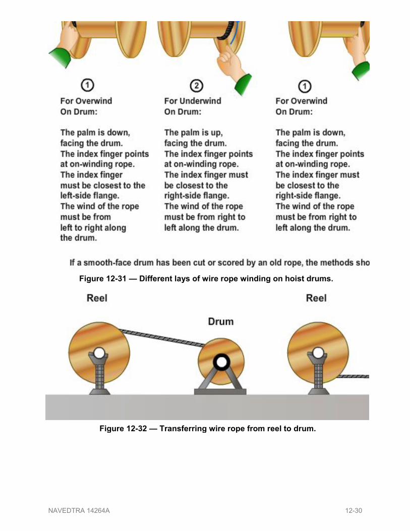